

Page 1
(9) Data Hold
Press the “D.HOLD” button on the meter to enter the data hold mode and press this
button again and the meter exits the data hold mode.
(10) Auto Power Off and Disable
1. When the meter has been turned on for 15 minutes without any action from the users,
the meter will automatically turn itself off.
2. To disable the Auto Power Off function, press any button when the meter is on or
switch the selector switch.
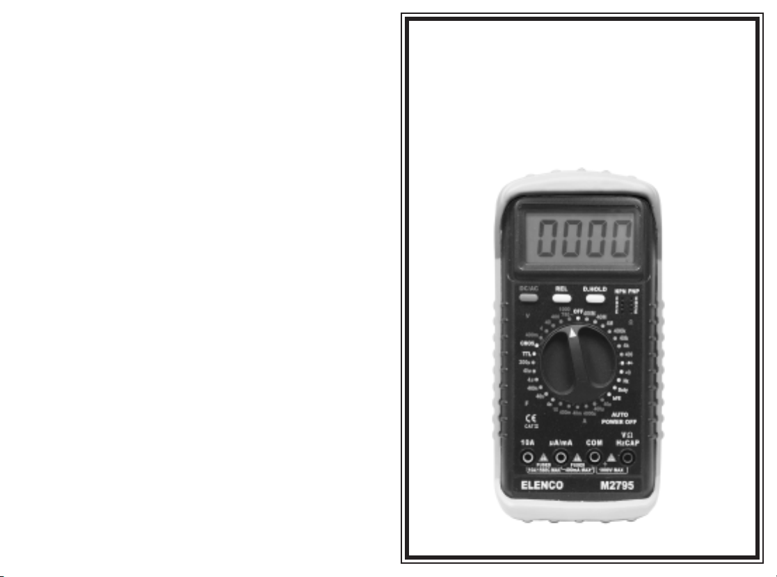
OPERATOR’S
INSTRUCTION MANUAL
M-2795
4. Care and Maintenance
4-1. Caring for Your Multimeter
Your digital multimeter is an example of superior design and craftsmanship. The following
suggestions will help you care for the multimeter so you can enjoy it for years.
1. Keep the multimeter dry. If it gets wet, wipe it dry immediately. Liquids can contain
minerals that can corrode electronic circuits.
2. Use and store the multimeter only in normal temperature environments. Extreme
temperatures can shorted the life of electronic devices, damage batteries, and distort
or melt plastic parts.
3. Handle the multimeter gently and carefully. Dropping it can damage the circuit boards
and case and can cause the multimeter to work improperly although the holster can
provide enough protection.
4. Keep the multimeter away from dust and dirt, which can cause premature wear of
parts.
5. Wipe the multimeter with a damp cloth occasionally to keep it looking new. Do not
use harsh chemicals, cleaning solvents, or strong detergents to clean the multimeter.
6. Use only fresh batteries of the required size and type. Always remove old or weak
batteries. They can leak chemicals that destroy electronic circuits.
4-2. Maintenance
9V Battery Replacement
1. Make sure that the instrument is not connected to any external circuit. Set the
selector switch to the OFF position and remove the test leads from the terminals.
2. Remove the screws from the bottom case and lift the case. Remove the spent battery
and replace it with a battery of the same type.
Fuse Replacement
Remove the screws from the bottom case and lift the case. Replace the fuse with the
same type and rating: 5 x 20mm 0.5A/250V fast-blow fuse or 5 x 20mm 10A/250V
fast-blow fuse as the replacements.
ElencoTMElectronics, Inc.
150 W. Carpenter Avenue
Wheeling, IL 60090
(847) 541-3800
http://www.elenco.com
e-mail: elenco@elenco.com
DIGITAL MULTIMETER
Copyright © 2003 ElencoTMElectronics, Inc.
Page 2
! WARNING !
PLEASE READ THIS INSTRUCTION MANUAL
CAREFULLY
Misuse and/or abuse of this instruction cannot be prevented by
any printed word and may cause injury and/or equipment
damage.
Please follow all these instructions and measurement
procedures faithfully, and adhere to all standard industrial
safety rules and practices.
The multimeter shall be used in over voltage category II !
1. Safety Information
To ensure that the meter is used safely, follow all of the safety and operation
instructions in this manual. If the meter is not used as described in the
manual, the safety features of the meter might be impaired.
• Turn off the power to the circuit under test before cutting, unsoldering, or
breaking the circuit. Small amounts of current can be dangerous.
• Use caution when working above 60VDC or 30VAC rms. Such voltages
pose a shock hazard.
• When using the test lead, keep your fingers behind the guards on the test
lead.
• Disconnect the live test lead before disconnecting the common test lead.
• To avoid damage to the meter, do not exceed the input limits.
• This digital multimeter is designed for indoor use only.
• This digital multimeter has a measuring deviation of 2.3% by immunity test
according to EN50082-1.
-2- -7-
(3) Resistance Measurement and Diode, Continuity Test
1. Connect the black test lead to the “COM” socket and the red test lead to the “VWCAP”
socket.
2. Set the selector switch to the desired “W”, “ ” or “ ” position.
3. Remove the power from the equipment under test, connect the probes across the
circuit to be tested.
CAUTION: Be sure that the circuit to be tested is “dead”. Max.input overload: 250Vrms
and <10sec.
NOTE: When testing 400M
then test.
W
resistance, short the test leads and press the “REL” button,
(4) Capacitance Measurement
1. Before testing, discharge the capacitor by shorting its leads together. Use caution in
handling the capacitors because they may have a charge on them of considerable
power before discharging.
2. Connect the black test lead to the “COM” socket and the red test lead to the “VWCAP”
socket.
3. Set the selector switch to the “F” position.
4. Press the “REL” button. You can use the relative function to eliminate the zero error.
5. Connect the probes across the capacitor to be tested.
NOTE: When testing a 200
m
F capacitor, note that there will be approx. 30 sec. time lag.
(5) Frequency and Duty Cycle Measurement
1. Connect the black test lead to the “COM” socket and the red test lead to the “VWCAP”
socket.
2. Set the selector switch to the “Hz” or “Duty” position.
3. Connect the probes across the source or load under measurement.
4. When using the 80KP-2 Adapter, the correct reading should be the reading on the
LCD display times 128.
(6) hFE Test
1. Set the selector switch to the desired “hFE” position (PNP or NPN type transistor).
2. Never apply an external voltage to the hFE sockets. Damage to the meter may result.
3. Plug the transistor directly into the hFE socket. The socket is labeled E, B, and C for
Emitter, Base, and Collector.
4. Read the h
FE (beta or DC current gain) in the display.
(7) Logic (TTL/CMOS) Test
1. Connect the black test lead to the “COM” socket and the red test lead to the “VWCAP”
socket.
2. Set the selector switch to the desired “TTL” or “CMOS” position.
3. Connect the probes across the source or load under measurement.
4. With a logic high pulse (1), the indicator will display on LCD. With a logic low pulse
(0), the indicator will appear on the LCD.
(8) Relative Value Display
Press the “REL” button on the meter to use the relative measurement mode. The
present value will be stored in memory. The new display value is equal to the
measurement value minus the stored value.
Example:
When you test the capacitance, you can use the Relative function to eliminate the
zero error.
Page 3

3. Operation
WARNING
1. When measuring voltage, be sure that the instrument is not connected or switched to
the resistance range. Always ensure that the correct terminals are used for the type
of measurement to be made.
2. Use extra care when measuring voltage above 50V, especially from sources where
high voltage is present.
3. Avoid making connections to live circuits whenever possible.
4. When making current measurements, be sure that the circuit is not live before
opening it to connect the test leads.
5. Before making resistance measurements or diode test, ensure that the circuit under
test is discharged.
6. Always ensure that the correct function and range is selected. If in doubt on which
range to use, start with the highest and work your way down.
7. Extreme care should be taken when using the instrument in conjunction with a current
transformer connected to the terminals if an open circuit occurs.
8. Ensure that the test leads and probes are in good condition with no damage to the
insulation.
9. Take care not to exceed the overload limits as shown in the specifications.
10. Before opening the case of the instrument to replace the battery, disconnect the test
leads from any external circuit, set the selector switch to the OFF position.
3-1. Check the Battery
If the battery is weak, a “ ” symbol will appear on the right of the display. It means
that the battery should be replaced.
3-2. How to Make a Measurement
(1) DC/AC Voltage Measurement
1. Connect the black test lead to the “COM” socket and the red test lead to the “VWCAP”
socket.
2. Set the selector switch to the desired “V” position, and press the “DC/AC” button to
choose the function. If the magnitude of the voltage is not known, set the selector
switch to the highest range and reduce until a satisfactory reading is obtained.
3. Connect the probes across the source or load under measurement.
(2) DC/AC Current Measurement
1. Set the selector switch to the desired “A” position, and press the “DC/AC” button to
choose the function. If the magnitude of the current is not known, set the selector
switch to the highest range and reduce until a satisfactory reading is obtained.
2. For current measurements less than 400mA, connect the black test lead to the “COM”
socket and the red test lead to the “mA/mA” socket.
3. For current measurements over 400mA, connect the black test lead to the “COM”
socket and the red test lead to the “10A” socket.
4. Disconnect the power from the circuit under test and open the normal circuit path
where the measurement is to be taken. Connect the meter in series with the circuit.
5. Do not continually measure 10A as the shunt wire will heat up. Allow 30 seconds
max. At 5A or less, continuous use is okay.
NOTE: BE SURE TO MEASURE WITHIN 30 SECONDS TO AVOID HIGH CURRENT
HAZARD.
+
Safety Symbols and Relative Symbols
This marking adjacent to another marking, terminal, or
operating device indicates that the operator must refer to
!
WARNING
CAUTION
500V max.
the explanation in the operating instructions to avoid
damage to the equipment and/or to avoid personal injury.
This WARNING sign denotes a hazard. It calls attention
to a procedure, practice or the like, which if not correctly
performed or adhered to, could result in personal injury.
This CAUTION sign denotes a hazard. It calls attention
to a procedure, practice or the like, which, if not correctly
adhered to, could result in damage to or destruction of
part or all of the instrument.
This marking advises the user that the terminal(s) so
marked must not be connected to a circuit point at which
the voltage, with respect to earth ground, exceeds (in
this case) 500 volts.
This symbol, adjacent to one or more terminals,
identifies them as being associated with ranges that may
in normal use be subjected to particularly hazardous
voltages.
For maximum safety, the instrument and its test leads
should not be handled when these terminals are
energized.
This marking indicates that equipment is protected
completely be the double insulation.
European safety standard.
DC (direct current).
DC and AC
AC (alternating current).
-3--6-
Page 4

2. Specifications
2-1. General Specifications
Display 3 3/4 digit LCD with a max. reading of 4000.
Range Control Manual range control.
Polarity Automatic negative polarity indication.
Zero Adjustment Automatic.
Overrange Indication “OL” on LCD is displayed.
Low Battery Indication “ ” sign on LCD readout.
Auto Power Off Approximately 15 minutes.
Safety Standards EMC/LVD. The meter is up to the
Operation Temperature 32
Storage Temperature –4
Power 9V battery.
Dimensions 7 5/8” (H) x 3 9/16” (W) x 1 3/4” (D)
Weight Approximately 0.66 lb. (w/o holster)
Accessories Safety Test Leads - 1 pair
2-2. Electrical Specifications
Accuracy is + (% or reading + number in last digit) at 23 + 5OC, <75% RH.
DC Voltage
400mV, 4V, 40V, 400V +(0.5% + 3)
1000V +
Impedance 10MW
Max. input: 250V~ on 400mV range; 1000V~ on all other ranges.
AC Voltage
4V, 40V, 400V +(0.8% + 3)
400mV, 750V +(1.2% + 3)
Impedance 10MW
Max. input: 250V~ on 400mV range; 1000V~ on all other ranges.
Resistance
400W, 4kW, 40kW, 400kW, 4MW +
40MW +
400MW +
Overload Protection 250V DC/ACrms
+
standards of IEC1010 Pollution Degree 2,
Overvoltage Catagory II.
O
F to 104OF (0OC to 40OC)
less than 85% relative humidity
O
F to 140OF (–20OC to 60OC)
less than 95% relative humidity
(w/o holster)
Operator’s Manual - 1 pc.
Holster - 1 pc.
Max. voltage from “VWmA”
socket to “COM” socket is
(0.8% + 3)
1000V~ from “COM” socket
to earth is 500V~.
(1% + 3)
(2% + 3)
(5% + 10)
DC Current
40mA, 400mA, 4000mA+
40mA, 400mA +
10A +(2% + 5)
(1.2% + 3)
(1.5% + 3)
Caution: Max. operation time 15s.
!
Overload Protection Fast 0.5A/250V, 10A/250V fuse.
AC Current
40mA, 400mA, 4000mA+
40mA, 400mA +
10A +(2.5% + 5)
(1.5% + 3)
(2% + 3)
Caution: Max. operation time 15s.
!
Overload Protection Fast 0.5A/250V, 10A/250V fuse.
Frequency Response 40 - 400Hz
Capacitance
4nF +
(5% + 10)
40nF +(3% + 10)
400nF, 4mF, 40mF+(2% + 5)
200mF+
(4% + 5)
Overload Protection 250V DC/ACrms
Frequency
Frequency 10Hz - 10MHz +(0.1% + 5)
Sensitivity Sine wave 0.6Vrms
Overload Protection 250V DC/ACrms
Duty Cycle
Duty Cycle 0.1% - 99.9% +
(2% + 2) Frequency lower than 10kHz
Sensitivity Sine wave 0.6Vrms
Overload Protection 250V DC/ACrms
Diode Test
Test Current: 1 +
0.6mA Test Voltage: Approx. 1.5V
Overload Protection 250V DC/ACrms
Continuity Test
Audible Indication Less than 120W approx.
Overload Protection 250V DC/ACrms
FE Test
h
Ib 10mA
Vce 2.5V approx.
Test Range 0 - 1000
Logic Test
TTL Logic 1: 2.5V +
0.8V Logic 0: 0.8V +0.5V
CMOS Logic 1: 4.0V +1.0V Logic 0: 2.0V +0.5V
Frequency Response: 20MHz
Detectable Pulse Width: 25ns min
-4- -5-
 Loading...