

Page 1
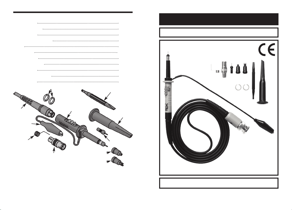
ACCESSORIES
BNC Adapter 591030
Spare Probe Tip 616002
Insulating Tip 626000
Channel Identifier Clip 626003
IC Tip 626041
Probe Body 626P3E
Adjusting Tool 629014
Sprung Earth Tip 680017
Sprung Hook 680912
BNC Cable Assembly 870030
Ground Lead 874010
Channel Identifier Clips
Adjusting Tool
Oscilloscope Probe Kit
Model P-3E
BNC Cable
Assembly
Ground Lead
Sprung Earth Tip
Made in Taiwan
Probe Body
BNC Adapter
ELENCO
Insulating Tip
®
150 W. Carpenter Avenue
Wheeling, IL 60090
(847) 541-3800
www.elenco.com
e-mail: elenco@elenco.com
IC Tip
Sprung Hook
Spare Probe Tip
Instruction Manual
ELENCO
Copyright © 2011 by ELENCO®All rights reserved. 753009
No part of this book shall be reproduced by any means; electronic, photocopying, or
otherwise without written permission from the publisher.
®
Page 2
INTRODUCTION
The P-3E is a passive, high-impedance oscilloscope probe designed and
calibrated for use with instruments having an input impedance of 1MΩ shunted
by 20pF. However, it may be compensated for use with instruments having an
input capacitance of 10 to 30pF. The probe incorporates a two position slide
switch in the head which selects attenuation of x1, x10 position or a ground
reference position.
SAFETY INSTRUCTIONS
Review the following safety precautions to avoid injury and prevent damage to
this product or any products connected to it.
• To avoid potential hazards, use this product only as specified.
• The common terminal is at ground potential. Do not connect the common
terminal to elevated voltages.
• Do not operate in an explosive atomosphere.
• Keep product surfaces clean and dry.
• If your probe requires cleaning, disconnect it from the instrument and clean
it with mild detergent and water. Make sure the probe is completely dry
before reconnecting it to the instrument.
MAINTENANCE
Before dismantling any part of the probe, make sure it is disconnected from
any voltage source. The probe body can be detached from the cable assembly
by unplugging the push-fit BNC connector from the probe body. This permits
replacement of the cable or body assembly should either part become
damaged. The probe tip is also replaceable. To replace a broken tip, hold the
black insulating part of the tip with pliers and unscrew it from the probe body.
Replace with a new tip, taking care to align with the inner contact.
SPECIFICATIONS
Position X10
Attenuation Ratio 10:1
Bandwidth DC to 250MHz
Rise Time 1.4nS
Input Resistance 10MΩ when used with oscilloscopes with 1MΩ
Input Capacitance Approx. 13pF
Compensation Range 10 to 30pF
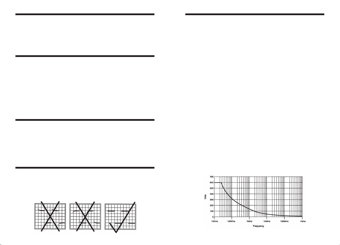
Working Voltage 600V CAT I, 300V CAT II (DC + peak AC) derating
Position REF
Probe tip opened, oscilloscope input grounded.
Position X1
Attenuation Ratio 1:1
Bandwidth DC to 6MHz
Rise Time 58nS
Input Resistance 1MΩ (oscilloscope input)
Input Capacitance 56pF plus oscilloscope capacitance
Working Voltage 300V CAT I, 150V CAT II (DC + peak AC) derating
Operating Temperature 32
Humidity 85% RH or less (at 95OF/35OC)
Safety Meets EN61010-031 CAT II
Cable Length 46.8” (1.2m)
input.
with frequency (see Figure 1)
with frequency
O
F (0OC) to 122OF (50OC)
COMPENSATION ADJUSTMENT
In order to obtain the correct division ratio with each oscilloscope, the
attenuation network needs to be adjusted. To compensate the probe to your
oscilloscope, apply a 1kHz square wave to the probe tip, or connect to the cal
socket on the oscilloscope to display a few cycles of the waveform and adjust
the trimmer located in the BNC plug for a flat-topped square wave.
Figure 1 - Voltage Derating Curve
 Loading...