

Elenco 100kHz Function Generator in Kit Form User Manual
FUNCTION GENERATOR KIT
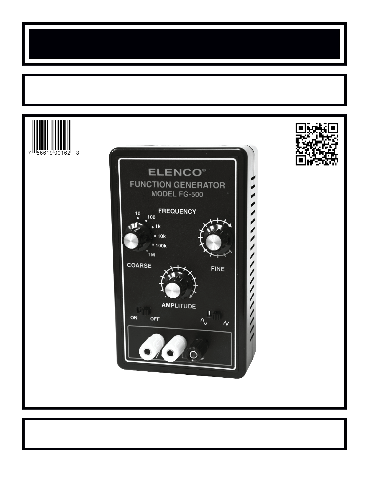
MODEL FG-500K
Assembly and Instruction Manual
ELENCO
®
Copyright © 2013 by Elenco®Electronics, Inc. All rights reserved. Revised 2013 REV-G 753069
No part of this book shall be reproduced by any means; electronic, photocopying, or otherwise without written permission from the publisher.

PARTS LIST
If you are a student, and any parts are missing or damaged, please see instructor or bookstore.
If you purchased this kit from a distributor, catalog, etc., please contact ELENCO®(address/phone/e-mail is at
the back of this manual) for additional assistance, if needed. DO NOT contact your place of purchase as they
will not be able to help you.
RESISTORS
Qty. Symbol Description Color Code Part #
! 1 R6 200Ω 5% ¼W red-black-brown-gold 132000
! 1 R1 620Ω 5% ¼W blue-red-brown-gold 136200
! 1 R5 3.9kΩ 5% ¼W orange-white-red-gold 143900
! 1 R7 8.2kΩ 5% ¼W gray-red-red-gold 148200
! 1 R8 10kΩ 5% ¼W brown-black-orange-gold 151000
! 1 R4 22kΩ 5% ¼W red-red-orange-gold 152200
! 1 R9 100kΩ 5% ¼W brown-black-yellow-gold 161000
! 1 R2 10kΩ Potentiometer 192531
! 1 R3 100kΩ Potentiometer 192612
CAPACITORS
Qty. Symbol Value Description Part #
! 1 C6 820pF (821) 10% Discap 228210
! 1 C5 .01µF (103) 10% Mylar 240119
! 1 C4 .1µF (104) 10% Mylar 251017
! 1 C3 1µF 50V Electrolytic (Lytic) 261047
! 3 C2, C7, C8 10µF 16V Electrolytic (Lytic) 271045
! 1 C1 100µF 16V Electrolytic (Lytic) 281044
! 1 C9 1,000µF 16V Electrolytic (Lytic) 291044
SEMICONDUCTORS
Qty. Symbol Value Description Part #
! 1 U1 XR-2206 Integrated circuit (IC) 332206
MISCELLANEOUS
-1-
Qty. Description Part #
! 1 PC board 511003
! 2 DPDT switch PC mount 541009
! 1 Switch rotary 2p6pos 542207
! 1 Battery snap 590098
! 1 Battery holder 590099
! 3 Knob 622009
! 1 Case top 623061
! 1 Case bottom 623062
! 1 Binding post black 625031
! 3 Nut binding post 625031HN
! 3 Lockwasher binding post 625031LW
! 2 Binding post yellow 625034
Qty. Description Part #
! 4 Screw 2.8 x 8mm 641102
! 3 Hex nut 7mm 644101
! 1 Hex switch nut 9 x 15mm 644102
! 2 Flat washer 8 x 14mm 645101
! 1 Flat washer 9mm 645103
! 4 Rubber foot 662015
! 1 16-pin IC socket 664016
! 1 Label top panel 721008
! 1” Double-sided tape 740020
! 9” Black wire 22ga. 814120
! 1 Lead-free solder 9LF99

-2-
PARTS VERIFICATION
Before beginning the assembly process, familiarize yourself with the components and this instruction book.
Verify that all of the parts are present. This is best done by checking off the parts in the parts list.
RESISTORS CAPACITORS SEMICONDUCTOR
Electrolytic
(radial)
Potentiometer
Knob
MISCELLANEOUS
PC board
Case top
Case bottom
Screws
2.8 x 8mm
7mm
Nuts Washers
Flat
8 x 14mm
Rubber foot
Label
Lead-free solder
Carbon film
Discap
Battery snap
Black wire 22ga.
Double-sided tape
Mylar
16-pin IC socket
XR-2206 Integrated
circuit (IC)
Rotary switch
DPDT switch
Binding posts
Black Yell ow
Binding post nut
Binding post
lockwasher
Battery holder
9mm
Flat
9 x 15mm

-3-
INTRODUCTION
IDENTIFYING CAPACITOR VALUES
Capacitors will be identified by their capacitance value in pF (picofarads), nF (nanofarads) or µF (microfarads). Most
capacitors will have their actual value printed on them. Some capacitors may have their value printed in the following manner.
IDENTIFYING RESISTOR VALUES
Use the following information as a guide in properly identifying the value of resistors.
BAND 1
1st Digit
Color Digit
Black 0
Brown 1
Red 2
Orange 3
Yello w 4
Green 5
Blue 6
Violet 7
Gray 8
White 9
BAND 2
2nd Digit
Color Digit
Black 0
Brown 1
Red 2
Orange 3
Yello w 4
Green 5
Blue 6
Violet 7
Gray 8
White 9
Multiplier
Color Multiplier
Black 1
Brown 10
Red 100
Orange 1,000
Yello w 10,000
Green 100,000
Blue 1,000,000
Silver 0.01
Gold 0.1
Resistance
Tolerance
Color Tolerance
Silver +10%
Gold +5%
Brown +1%
Red +2%
Orange +3%
Green +.5%
Blue +.25%
Violet +.1%
Bands
1 2
Multiplier
Tolerance
Electrolytic capacitors have a positive and a
negative electrode. The negative lead is
indicated on the packaging by a stripe with
minus signs and possibly arrowheads. Also, the
negative lead of a radial electrolytic is shorter
than the positive one.
Warning:
If the capacitor is connected
with incorrect polarity, it may
heat up and either leak, or
cause the capacitor to
explode.
OUTPUT:
• Waveforms: Sine, Triangle, Square
• Impedance: 600Ω + 10%.
• Frequency: 1Hz - 1MHz in 6 decade steps with variable
ranges.
SINE WAVE:
• Amplitude: 0 - 3Vpp
• Distortion: Less than 1% (at 1kHz)
• Flatness: +0.05dB 1Hz - 100kHz
SQUARE WAVE:
• Amplitude: 8V (no load)
• Rise time: Less than 50ns (at 1kHz)
• Fall time: Less than 30ns (at 1kHz)
• Symmetry: Less than 5% (at 1kHz)
TRIANGLE WAVE:
• Amplitude: 0 - 3Vpp
• Linearity: Less than 1% (up to 100kHz)
POWER REQUIREMENTS:
• Standard 9V battery
OPERATING TEMPERATURE:
• 0OC to 50OC
Polarity
marking
(+)
(–)
Multiplier
For the No. 0 1 2 3 4 5 8 9
Multiply By 1 10 100 1k 10k 100k .01 0.1
Second digit
First digit
Multiplier
Tolerance*
Note: The letter “R” may be
used at times to signify a
decimal point; as in 3R3 = 3.3
103K
100V
The letter M indicates a tolerance of +20%
The letter K indicates a tolerance of +10%
The letter J indicates a tolerance of +5%
Maximum working voltage
The value is 10 x 1,000 =
10,000pF or .01µF 100V
*
Assembly of your FG-500 Function Generator will
prove to be an exciting project and give much
satisfication and personal achievement. The FG-500
contains a complete function generator capable of
producing sine, square and triangle wave forms. The
frequency of this generator can be contiuously varied
from 1Hz to 1MHz in 6 steps. A fine frequency control
makes selection of any frequency in between easy.
The amplitude of the wave forms are adjustable from
0 to 3Vpp. This complete function generator system
is suitable for experimentation and applications by
the student. The entire function generator is
comprised of a single XR-2206 monolithic IC and a
limited number of passive circuit components.
SPECIFICATIONS

-4-
CONSTRUCTION
Solder
Soldering Iron
Foil
Solder
Soldering Iron
Foil
Component Lead
Soldering Iron
Circuit Board
Foil
Rosin
Soldering iron positioned
incorrectly.
Solder
Gap
Component Lead
Solder
Soldering Iron
Drag
Foil
1. Solder all components from the
copper foil side only. Push the
soldering iron tip against both the
lead and the circuit board foil.
2. Apply a small amount of solder to
the iron tip. This allows the heat
to leave the iron and onto the foil.
Immediately apply solder to the
opposite side of the connection,
away from the iron. Allow the
heated component and the circuit
foil to melt the solder.
1. Insufficient heat - the solder will
not flow onto the lead as shown.
3. Allow the solder to flow around
the connection. Then, remove
the solder and the iron and let the
connection cool. The solder
should have flowed smoothly and
not lump around the wire lead.
4.
Here is what a good solder
connection looks like.
2. Insufficient solder - let the
solder flow over the connection
until it is covered.
Use just enough solder to cover
the connection.
3. Excessive solder - could make
connections that you did not
intend to between adjacent foil
areas or terminals.
4. Solder bridges - occur when
solder runs between circuit paths
and creates a short circuit. This is
usually caused by using too
much solder.
To correct this, simply drag your
soldering iron across the solder
bridge as shown.
What Good Soldering Looks Like
A good solder connection should be bright, shiny, smooth, and uniformly
flowed over all surfaces.
Types of Poor Soldering Connections
Introduction
The most important factor in assembling your FG-500K Function
Generator Kit is good soldering techniques. Using the proper soldering
iron is of prime importance. A small pencil type soldering iron of 25 watts
is recommended. The tip of the iron must be kept clean at all times
and well-tinned.
Solder
For many years leaded solder was the most common type of solder
used by the electronics industry, but it is now being replaced by leadfree solder for health reasons. This kit contains lead-free solder, which
contains 99.3% tin, 0.7% copper, and has a rosin-flux core.
Lead-free solder is different from lead solder: It has a higher melting
point than lead solder, so you need higher temperature for the solder to
flow properly. Recommended tip temperature is approximately 700OF;
higher temperatures improve solder flow but accelerate tip decay. An
increase in soldering time may be required to achieve good results.
Soldering iron tips wear out faster since lead-free solders are more
corrosive and the higher soldering temperatures accelerate corrosion,
so proper tip care is important. The solder joint finish will look slightly
duller with lead-free solders.
Use these procedures to increase the life of your soldering iron tip when
using lead-free solder:
● Keep the iron tinned at all times.
● Use the correct tip size for best heat transfer. The conical tip is the
most commonly used.
● Turn off iron when not in use or reduce temperature setting when
using a soldering station.
●
Tips should be cleaned frequently to remove oxidation before it becomes
impossible to remove. Use Dry Tip Cleaner (Elenco®#SH-1025) or Tip
Cleaner (Elenco®#TTC1). If you use a sponge to clean your tip, then use
distilled water (tap water has impurities that accelerate corrosion).
Safety Procedures
● Always wear safety glasses or safety goggles to
protect your eyes when working with tools or
soldering iron, and during all phases of testing.
● Be sure there is adequate ventilation when soldering.
●
Locate soldering iron in an area where you do not have to go around
it or reach over it. Keep it in a safe area away from the reach of
children.
● Do not hold solder in your mouth. Solder is a toxic substance.
Wash hands thoroughly after handling solder.
Assemble Components
In all of the following assembly steps, the components must be installed
on the top side of the PC board unless otherwise indicated. The top
legend shows where each component goes. The leads pass through the
corresponding holes in the board and are soldered on the foil side.
Use only rosin core solder.
DO NOT USE ACID CORE SOLDER!
 Loading...