

Page 1
ВОЗДУШНЫЙ КОНДИЦИОНЕР
SPT-7090
РУКОВОДСТВО ПОЛЬЗОВАТЕЛЯ
Page 2

СОДЕРЖАНИЕ
ИНСТРУКЦИЯ ПО ЭКСПЛУАТАЦИИ ………………………………………………………… 3
Введение ………………………………………………………………………………………… 4
Меры предосторожности …………………………………………………………………… 4
Описание прибора ………………………………………………………………………… 5
Пульт дистанционного управления (ПДУ) ……………………………………………… 6
Специальные функции ……………………………………………………………………… 8
Панель управления ………………………………………………………………………… 10
Чистка …………………………………………………………………………………………… 10
Проверка перед эксплуатацией ………………………………………………………… 11
Хранение ……………………………………………………………………………………… 11
Устранение неполадок …………………………………………………………………… 12
ИНСТРУКЦИЯ ПО УСТАНОВКЕ ……………………………………………………………… 14
Важная информация ……………………………………………………………………… 15
Указания по выбору места установки ………………………………………………… 15
Выбор места установки внутреннего блока ………………………………………… 15
Выбор места установки внутреннего блока ………………………………………… 15
Меры предосторожности ………………………………………………………………… 16
Требования по заземлению ……………………………………………………………… 16
Дополнительные предупреждения ……………………………………………………… 16
Диаграмма установки …………………………………………………………………… 17
Установка внутреннего блока …………………………………………………………… 18
Установка внешнего блока ……………………………………………………………… 19
Установка и обслуживание фильтра ………………………………………………… 21
Проверка после установки ……………………………………………………………… 22
Тестирование прибора …………………………………………………………………… 22
СПЕЦИФИКАЦИЯ ……………………………………………………………………………… 23
2
Page 3

ИНСТРУКЦИЯ ПО ЭКСПЛУАТАЦИИ
3
Page 4
ВВЕДЕНИЕ
УВАЖАЕМЫЙ ПОКУПАТЕЛЬ!
Мы поздравляем Вас с удачным выбором!
Вы стали обладателем продукции марки ELENBERG, которая отличается прогрессивным дизайном и хорошим качеством исполнения.
Мы надеемся, что наша продукция станет Вашим спутником на долгие
годы.
МЕРЫ ПРЕДОСТОРОЖНОСТИ
Чтобы максимально полно и безопасно использовать данный прибор, пожалуйста, внимательно прочитайте руководство пользователя.
• При высоком напряжении электросети компоненты системы могут быть
повреждены. Низкое напряжение в электросети может привести к поломке
системы хладагента. Для нормальной работы прибора напряжение в электросети должно быть стабильным.
• Отключайте прибор от электросети, если не собираетесь использовать его
в ближайшее время.
• Не укорачивайте шнур питания и не используйте удлинители для подключения прибора к электросети.
• Не блокируйте воздухозаборные и воздухоотводные отверстия прибора - это
может привести к поломке прибора.
• Не открывайте окна и двери во время работы прибора.
• Перед подключением прибора к электросети убедитесь, что ее характеристики соответствуют спецификации прибора.
Прибор оснащен системой автоматического включения/выключения. Пожа-
луйста, не включайте/выключайте прибор вручную слишком часто.
• При появлении дыма или неприятного запаха немедленно отключите прибор от электросети и обратитесь в сервисный центр.
• Не используйте аэрозоли ближе чем за 1 м до прибора - это может привести к возгоранию.
• Не пытайтесь самостоятельно починить прибор, любой ремонт должен осуществляться в сервисном центре.
• Если шнур питания прибора поврежден, он должен быть заменен квалифицированным специалистом.
• Не вставляйте пальцы или какие-либо предметы в отверстия прибора.
• Не направляйте воздушный поток непосредственно на животных или растения.
• Не находитесь под потоком холодного воздуха слишком долго - это вредно
для здоровья.
• Используйте прибор только по его прямому назначению.
• Не допускайте попадания воды на прибор.
• Устанавливайте нагревательные приборы и прочие источники тепла вблизи
от кондиционера.
Дополнительные положения
Принцип работы прибора:
Кондиционер абсорбирует тепло помещения и выводит его через внешний
блок на улицу. Эффективность работы прибора зависит от многих факторов, включая температуру окружающей среды.
4
Page 5
Система защиты от замерзания
Когда кондиционер работает в режиме охлаждения при низкой температу-
ре окружающей среды, возможно образование льда на элементах теплообмена. Если температура теплообменника внутреннего блока опускается
неже 0 ºС, кондиционер автоматически выключается.
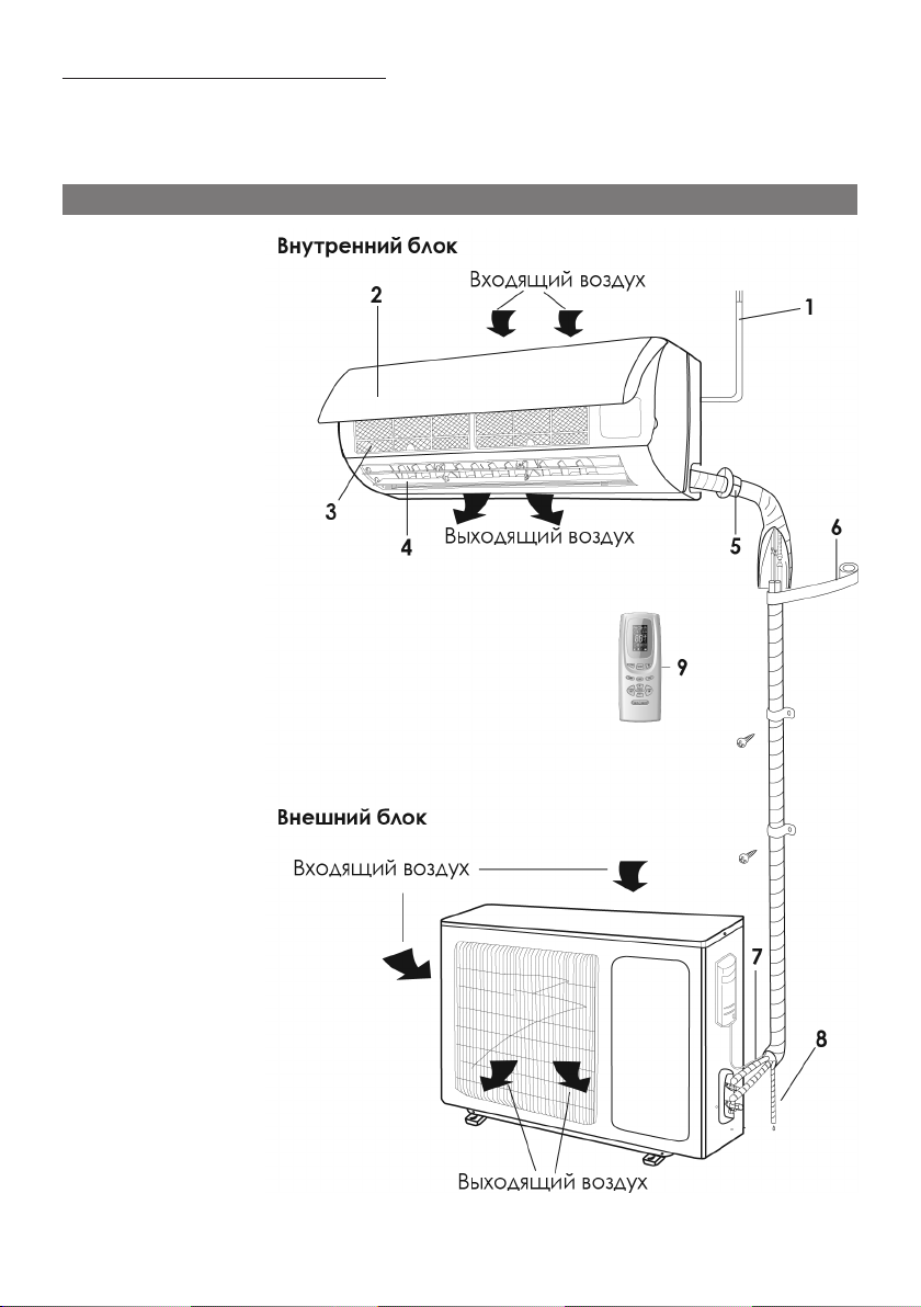
ОПИСАНИЕ ПРИБОРА
1. Шнур питания
2. Передняя панель
3. Фильтр
4. Жалюзи
5. Соединительные трубки
6. Оберточная пленка
7. Соединительные
провода
8. Отводящие трубки
9. Пульт дистанционного
управления (ПДУ)
5
Page 6

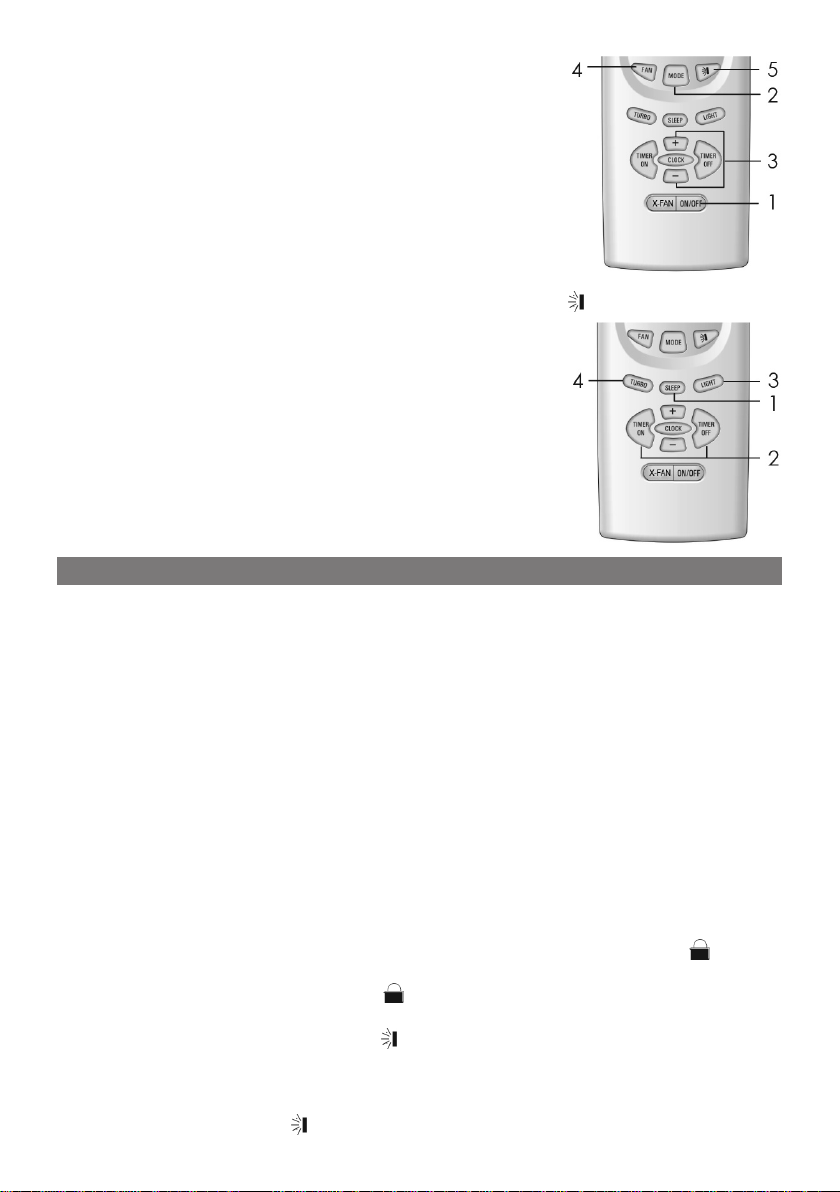
ПУЛЬТ ДИСТАНЦИОННОГО УПРАВЛЕНИЯ (ПДУ)
Описание кнопок ПДУ
• Для нормальной передачи сигнала между ПДУ и прибором не должно быть препятствий;
• Будьте осторожны - пульт чувствителен к внешнему механическому воздействию;
• Не допускайте попадания воды на ПДУ.
• Не оставляйте ПДУ возле источников тепла или под прямыми солнечными лучами.
Кнопка “Вкл./Выкл.” (ON/OFF)
Используйте эту кнопку, чтобы включать/выключать прибор.
При выключении прибора функции “Таймер” и “Сон” выключаются, но текущее время поддерживается.
Кнопка “Режим” (MODE)
Используйте эту кнопку для пе-
реключения между режимами “Авто” ( ) - “Охлаждение” ( ) - “Осушение” ( )
- “Вентиляция” ( ) - "Обогрев" ( ). По умолчанию установлен режим “Авто” и температура 25 ºC.
Кнопка “Сон” (SLEEP)
Используйте эту кнопку для включения/выключения функ-
ции “Сон”. Эта функция позволяет установить на таймере время, через которое кондиционер должен выключиться. Функция “Сон” не доступна в режимах “Вентиляция” и “Авто”.
Кнопка “Вентилятор” (FAN)
Используя эту кнопку, Вы можете устанавливать
скорость вращения вентилятора: “Авто” - “Низкая” ( ) - “Средняя” ( ) “Высокая” ( ). По умолчанию установлена скорость вращения “Авто”.
При использовании режима “Осушение” вентилятор работает только на
низкой скорости.
Кнопка “Часы” (CLOCK)
Нажмите эту кнопку, чтобы войти в режим настройки часов. При этом на
экране ПДУ начнет мигать индикатор “ ”. В течение следующих 5 секунд Вы
можете установить время. Для установки времени используйте кнопки “+” и
“-”. Чтобы увеличить/уменьшить значение времени на 10, нажмите и удерживайте кнопку “+” или “-” соответственно. Чтобы сохранить установленное
значение времени, нажмите кнопку “CLOCK”. При этом индикатор “ ” перестанет мигать. Если на экране ПДУ отображается время, но не отображается индикатор “ ”, значит это время таймера, а не текущее время.
Кнопка “Осушение” (X-FAN)
Эта функция позволяет высушить системы внутреннего блока перед полным
выключением прибора.
Нажмите кнопку "X-FAN" в режиме "Охлаждение" или "Осушение", на дис-
плее загорится индикатор " ", при этом вентилятор продолжит работать
ещё в течение 10 минут, даже, если Вы выключили прибор.
Изначально эта функция выключена.
Функция осушение не работает в режимах "Авто", "Вентиляция" и "Обогрев".
Кнопка “Ускорение” (TURBO)
Функция ускорение работает только в режиме “Охлаждение”. Нажмите
6
Page 7

кнопку TURBO, чтобы установить максимальную скорость воздушного потока.
Эта функция автоматически выключается при ручной установке скорости
воздушного тока.
Кнопка “+”
Используйте эту кнопку для увеличения температуры и показателей той или
иной функции. Нажмите и удерживайте эту кнопку для ускоренного увеличения текущего показателя. Эта кнопка не влияет на работу режима “Авто”.
Диапазон устанавливаемой температуры: 16 - 30 ºС (61 - 86 ºF).
Кнопка “-”
Используйте эту кнопку для уменьшения температуры и показателей той
или иной функции. Нажмите и удерживайте эту кнопку для ускоренного
уменьшения текущего показателя. Эта кнопка не влияет на работу режима
“Авто”.
Кнопка “Подсветка” (LIGHT)
Используя эту кнопку, Вы можете включить или выключить подсветку. По умол-
чанию подсветка включена.
Кнопка
Эта кнопка регулирует вертикальное положение
жалюзи. Вы можете выключить жалюзи, установить
диапазон их перемещения или зафиксировать под
определенным углом (рисунок справа).
При каждом нажатии этой кнопки включается очередной ре-
жим и загорается соответствующий индикатор.
При включении режима “ ” жалюзи начинают непрерывно двигаться от верх-
него положения в нижнее и обратно.
При выключении этой функции жалюзи фиксируются в том положении, в ко-
тором они находились в момент нажатия кнопки .
Кнопка “Таймер включения” (TIMER ON)
Используйте эту кнопку для настройки таймера включения.
Функция “Таймер включения” позволяет включить прибор в установленное
Вами время.
При активации таймера включения на экране ПДУ загорается индикатор
“ON” и погасает индикатор “ ”. В течение 5 секунд Вы можете установить
время таймера, используя кнопки “+”/“-”. При каждом нажатии на кнопки
“+”/“-” время увеличивается/уменьшается на 1 минуту. Для быстрого увеличения/уменьшения времени нажмите и удерживайте кнопку “+” или “-”.
После того, как Вы установите время таймера, нажмите кнопку “TIMER ON”
для подтверждения. Если после этого снова нажать кнопку “TIMER ON”, функция “Таймер включения” будет выключена.
Кнопка “Таймер выключения” (TIMER OFF)
Используйте эту кнопку для настройки таймера выключения.
Функция “Таймер выключения” позволяет выключить прибор в установленное
Вами время.
Таймер этой функции настраивается аналогично таймеру включения (см.
выше).
7
Page 8
Основные операции
1. Нажмите кнопку ON/OFF, чтобы включить/выключить
прибор.
Замечание:Привыключениикондиционера жалю-
зиавтоматическизакрываются.
2. Используя кнопку MODE, установите нужный Вам
режим.
3. Установите наиболее комфортную температуру с
помощью кнопок +/-.
4. Чтобы установить скорость воздушного потока, используйте кнопку FAN.
5. Для контроля положения жалюзи используйте кнопку .
Дополнительные операции
1. Для активации функции “Сон” нажмите кнопку
SLEEP.
2. Чтобы использовать функцию “Таймер включения”
или “Таймер выключения”, нажмите кнопку TIMER
ON или TIMER OFF.
3. Для включения/выключения подсветки используйте
кнопку LIGHT.
4. Чтобы включить максимальную скорость воздушного потока, нажмите кнопку TURBO.
СПЕЦИАЛЬНЫЕ ФУНКЦИИ
Функция “Осушение”
Эта функция позволяет избежать образования конденсата в воздушной системе кондиционера после его выключения.
1. Если эта функция включена, то после нажатия кнопки ON/OFF вентилятор
кондиционера будет работать еще 10 минут на низкой скорости. Чтобы выключить его нажмите кнопку BLOW.
2. Если эта функция выключена, то после нажатия кнопки ON/OFF кондиционера сразу выключится.
Автоматический режим
При включении автоматического режима кондиционер сам выбирает наиболее комфортный температурный режим.
Функция “Турбо”
Эта функция позволяет за кратчайшее время достигнуть установленной Вами
температуры.
Блок кнопок
Одновременно нажмите кнопки + и -, чтобы заблокировать клавиатуру ПДУ. Когда включен блок кнопок, на экране ПДУ отображается индикатор “ ”. Чтобы
выключить блок кнопок, одновременно нажмите кнопки + и -. После выключения
блока кнопок погасает индикатор “ ”.
Вертикальное положение жалюзи
1. Нажмите и удерживайте кнопку , чтобы включить последовательное движение жалюзи сверху вниз и снизу вверх. После того, как Вы отпустите эту кнопку, жалюзи зафиксируются в текущем положении.
2. Если жалюзи последовательно движутся сверху вниз и снизу вверх, нажмите
и удерживайте кнопку , чтобы выключить их.
8
Page 9
Переключение единиц измерения (ºС/ºF)
Когда кондиционер выключен, одновременно нажмите кнопки MODE и -, чтобы
переключиться на другие единицы измерения (ºC или ºF).
Режим “Разморозка”
Если Вы включите режим “Разморозка”, то кондиционер невозможно будет остановить до тех пор, пока полный цикл операций этого режима не будет выполнен.
Чтобы включить этот режим, одновременно нажмите кнопки MODE и BLOW. Когда включен режим “Разморозка”, на экране ПДУ отображается надпись “H1”.
Чтобы просмотреть установленную температур, нажмите кнопку + или -.
Режим "Обогрев"
В режиме "Обогрев" прибор переносит тёплый воздух от внешнего блока к внутреннему. При снижении температуры окружающей среды эффективность
обогрева снижается.
Разморозка:
• При низкой температуре и высокой влажности окружающей среды возможно образование наледи на внешнем блоке. В этом случае включается режим "Авто разморозки" и работа режима "Обогрев" приостанавливается на
8 - 10 минут.
• Во время разморозки выключаются вентиляторы внешнего и внутреннего
блоков.
• Во время разморозки индикаторы внутреннего блока могут мигать - это нормально и не является неисправностью.
• Работа режима "Обогрев" возобновляется автоматически.
Функция защиты от холодного воздуха:
Если воздух, подаваемый внешним блоком, нагрет недостаточно, то вентилятор
внутреннего блока начнёт работать, только через 3 минуты после включения режима "Обогрев". Подобная ситуация может возникнуть:
1) если режим "Обогрев" был только что включён;
2) если прибор работал в режиме "Авто-разморозки";
3) если температура окружающей среды слишком низкая.
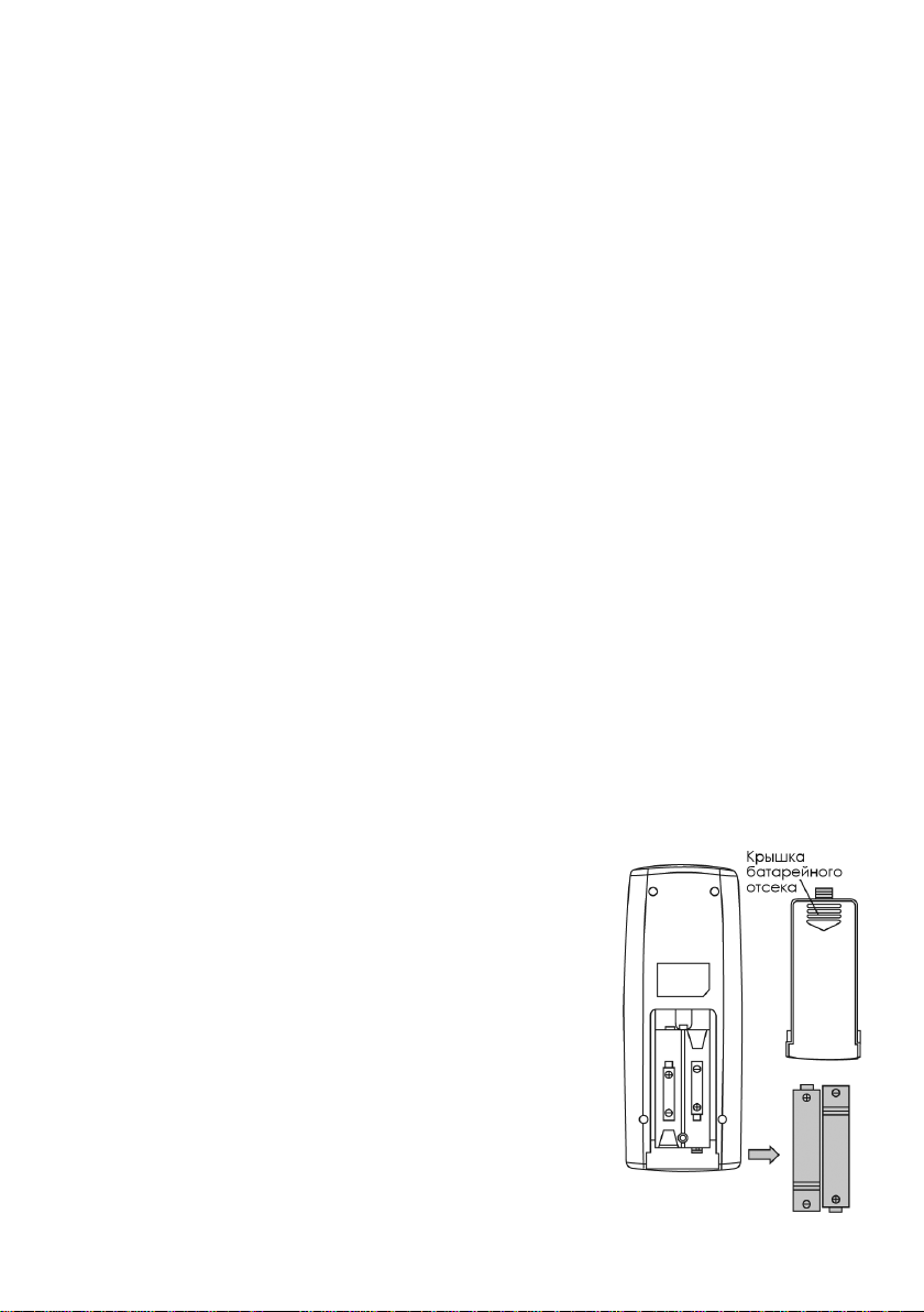
Замена батарей ПДУ
Пульт дистанционного управления работает от двух батарей 1,5 В типа AAA.
1. Откройте крышку батарейного отсека и установите
две батареи, соблюдая полярность (рисунок справа).
2. Закройте крышку батарейного отсека.
Замечания:
• Призаменебатарейнеустанавливайтеновыебатареиодновременносостарыми.
• ИзвлекайтебатареиизПДУ, если не собираетесь
использоватьеговближайшеевремя.
• Еслирадиусдействия ПДУ снизился,заменитебатареи.
• Расстояние до приборов принимающих или излучающихрадиоволныдолжнобытьнеменее1м.
• Есливработепультапоявилисьнеполадки,извлекитебатареииподождите30секунд.Установитебатареинаместо.
9
Page 10
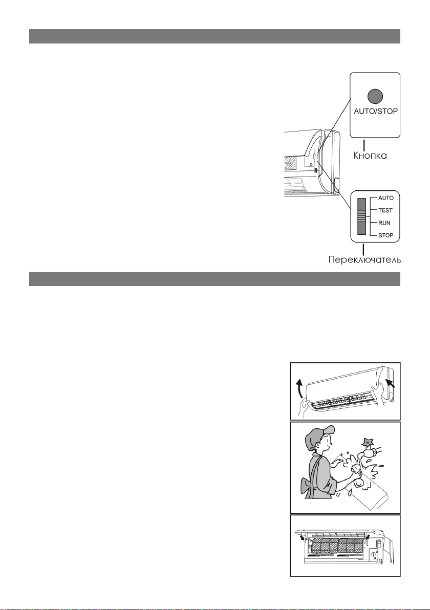
ПАНЕЛЬ УПРАВЛЕНИЯ
Панель управления, расположенная на внутреннем блоке кондиционера,
включает в себя кнопку “Авто/Стоп” (AUTO/STOP) и переключатель режимов.
Функции кнопки “Авто/Стоп” (AUTO/STOP):
• Нажмите эту кнопку, когда кондиционер выключен, чтобы включить автоматический режим работы. В этом режиме кондиционер сам выберет
оптимальную температуру и скорость вращения
вентилятора.
• Если кондиционер работает, нажмите эту кнопку, чтобы выключить его.
Переключатель режимов:
• Если кондиционер выключен, переведите переключатель в положение “AUTO”, чтобы включить
автоматический режим работы; в положение
“TEST”, чтобы включить тестовый режим работы,
после выполнения тестового режима прибор автоматически выключится.
• Если кондиционер работает, переведите переключатель в положение “STOP”, чтобы выключить
его.
ЧИСТКА
Предупреждение:
• Отключайте прибор от электросети перед чисткой.
• Не разбрызгивайте воду на прибор - это может привести к короткому замыканию.
• Не используйте спиртосодержащие жидкости для чистки прибора.
• Протирайте корпус прибора мягкой влажной тканью.
Чистка передней панели
1. Снимите переднюю панель (рисунок справа).
Поднимите переднюю панель вверх следуя стрел-
кам. Держа панель двумя руками, снимите её,
применив незначительное усилие.
2. Чистка
Протирайте корпус прибора мягкой тканью с не-
большим количеством нейтрального моющего
средства.
Замечания:
• Если панель оснащена ЖК-экраном, извлеките
его перед чисткой передней панели.
• Температура воды не должна превышать 45 ºC.
3. Установка передней панели
Вставьте два суппорта передней панели в соответ-
ствующие разъемы на корпусе внутреннего блока, как показано на рисунке справа, и закройте
ее.
10
Page 11
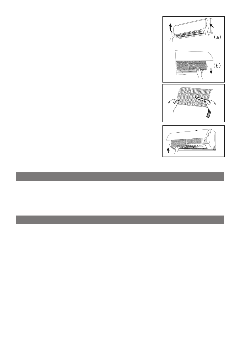
Чистка воздушного фильтра
Загрязненный фильтр снижает эффективность работы прибора. Регулярно производите чистку воздушного фильтра. При извлечение воздушного фильтра
не прикасайтесь к решетке радиатора.
1. Извлечение фильтра
а) Поднимите переднюю панель внутреннего бло-
ка.
b) Извлеките фильтр из прибора (рисунок спра-
ва).
2. Чистка
Для чистки фильтра можно использовать пылесос.
Также фильтр можно промыть в теплой воде.
Если на фильтре скопился жир, замочите его в
теплой воду, а потом снимите жир с помощью
скребка.
Замечания:
• Температураводынедолжнапревышать45ºC.
• Неподноситефильтрк источникамтеплаиот-
крытого пламени - это может привести к деформацииивозгораниюфильтра.
3. Установка фильтра
Установите фильтр на место. Аккуратно надавите
на фильтр до щелчка, чтобы зафиксировать.
1. Убедитесь, что вентиляционные отверстия прибора не заблокированы.
ПРОВЕРКА ПЕРЕД ЭКСПЛУАТАЦИЕЙ
2. Убедитесь, что прибор правильно заземлен.
3. Проверьте батареи в ПДУ.
4. Проверьте надежность крепления внешнего и внутреннего блоков. Проверьте герметичность соединений между блоками.
1. Отключите прибор от электросети.
ХРАНЕНИЕ
2. Почистите внутренний и внешний блоки. Почистите фильтры.
3. Проверьте внешний блок на наличие ржавчины. При необходимости покройте ржавые места краской.
11
Page 12
УСТРАНЕНИЕ НЕПОЛАДОК
ВНИМАНИЕ:
• Любойремонтприборадолженосуществлятьсявсервисномцентре.
• Внимательнопрочитайтеданныйраздел перед тем,какобратитьсяв сервисныйцентр.
ПРОБЛЕМА РЕШЕНИЕ
Кондиционер не запускается сразу после
остановки.
Воздух, выходящий из
кондиционера при его
запуске, имеет неприятный запах.
Во время работы кондиционера слышен
звук текущей воды.
При работе в режиме
охлаждения у выходного отверстия кондиционера образуется пар.
При запуске и остановке кондиционера
слышно потрескивание.
Кондиционер не включается.
Кондиционер охлаждает/обогревает не
достаточно эффективно.
Пульт дистанционного
управления не работает.
Защитная система кондиционера не позволяет запускать его ранее, чем через 3 минуты после остановки.
• Почистите воздушный фильтр.
• Если чистка фильтра не помогла, обратитесь в
сервисный центр
Вы слышите течение хладагента по системе кондиционера - это нормально.
Возникновение пара возможно при относительной
высокой температуре и уровне влажности в помещении. С понижением температуры в помещении
пар пропадет.
Этот звук вызван незначительной деформацией
пластиковых частей кондиционера при перемене
температуры и не является дефектом.
• Убедитесь, что прибор подключен к электросети.
• Убедитесь, что сеть находится под напряжением.
• Проверьте предохранители.
• Убедитесь, что характеристики электросети совпадают со спецификацией прибора. (Профессиональное тестирование)
• Проверьте настройку таймера включения.
• Проверьте настройку температуры.
• Убедитесь, что воздухозаборные и воздухоотводные отверстия прибора не заблокированы.
• Почистите фильтр.
• Убедитесь, что все двери и окна в помещении
закрыты.
• Проверьте скорость вращения вентилятора.
• Убедитесь, что в комнате нет сильных источников
тепла.
• Отключите прибор от электросети на несколько
секунд. Снова подключите прибор к электросети.
• Между ПДУ и прибором имеется препятствие.
• Замените батареи ПДУ.
• Убедитесь, что ПДУ не поврежден.
12
Page 13

С внутреннего блока
капает вода.
С внешнего блока
капает вода.
Работа внутреннего
блока сопровождается
ощутимым шумом.
Из внутреннего блока
не выходит воздух.
На жалюзи образуются
капли воды.
Немедленно отключите прибор от электросети и обратитесь в сервисный центр
при возникновении следующих ситуаций:
• Резкие звуки во время работы прибора.
• Сильный неприятный запах во время работы прибора.
• Вода скапливается возле внутреннего блока.
• Слишком часто включается система защиты прибора.
• Внутрь прибора попал посторонний предмет.
• На прибор была случайно пролита вода.
• Шнур питания и штепсель слишком сильно нагреваются.
• В приборе образовалось чрезмерное количество конденсата. Слишком высокая влажность в
помещении.
• Проверьте герметичность дренажного соединения.
• При работе режима охлаждение возможно образование конденсата на соединительных трубках.
• Образование воды возможно при работы режима “Разморозка”.
• Во время работы режима "Обогрев" конденсат
может скапливаться на частях теплообменной
системы.
• Это может быть звук переключающихся реле вентилятора или компрессора.
• Возникновение шума возможно во время работы
режима “Разморозка”.
• При работе режима “Осушение” вентилятор кондиционера может выключаться, чтобы предупредить образование конденсата.
• Если, при использовании режима "Обогрев",
температура теплообменной системы внутреннего блока слишком низкая. Прибор будет постепенно прогревать её. Воздушный поток пойдёт через 3 минуты после включения режима
"Обогрев".
• Это вызвано низкой температурой или высокой
влажностью воздуха в месте, в котором установлен внешний блок. При включении режима "Обогрев", тёплый воздух начнёт подаваться через 3
- 12 минут. В этот промежуток времени прибор
работает в режиме "Разморозка".
Прибор долго работал при высокой влажности в помещении.
13
Page 14

ИНСТРУКЦИЯ ПО УСТАНОВКЕ
14
Page 15
ВАЖНАЯ ИНФОРМАЦИЯ
1. Установка данного оборудования должна производиться квалифицированным персоналом.
2. Если шнур питания прибора не оснащен штепселем, подключите его напрямую к электросети, предварительно установив переключатель. Расстояние между контактами переключателя должно быть не менее 3 мм.
УКАЗАНИЯ ПО ВЫБОРУ МЕСТА УСТАНОВКИ
НЕ устанавливайте прибор в следующих местах:
• Вблизи от источников тепла (электрические и газовые плиты, обогреватели
и т.п.).
• Вблизи от медицинского оборудования или оборудования, излучающего
сильные электромагнитные волны.
• Сторона дома, выходящая на побережье моря или океана.
• Помещения, воздух которых может содержать пары масла.
• Помещения, где возможно скопление газа и прочих горючих веществ.
• Другие места, имеющие специальные ограничения.
ВЫБОР МЕТА УСТАНОВКИ ВНУТРЕННЕГО БЛОКА
1. Воздухозаборные и воздухоотводные отверстия прибора не должны блокироваться окружающими предметами. Воздушный поток должен свободно
проходить через все помещение.
2. Место установки должно позволять свободно удалять воду, которая может
образоваться возле блока.
3. Устанавливайте прибор в недоступном для детей месте.
4. Основание, на котором закреплен прибор, должно выдерживать его вес.
5. Кондиционер должен быть установлен на высоте не ниже 230 см от пола.
6. Расстояние до окружающих электрических приборов должно быть не менее 1 м.
7. Место установки должно обеспечивать легкий доступ к фильтру.
8. Место установки должно удовлетворять показателям диаграммы установки (см. далее).
ВЫБОР МЕСТА УСТАНОВКИ ВНЕШНЕГО БЛОКА
1. Шум и воздушный поток, исходящие от внешнего блока, не должны причинять неудобства соседям, животным и растениям.
2. Место установки должно быть хорошо проветриваемо.
3. Воздухозаборные и воздухоотводные отверстия прибора не должны блокироваться окружающими предметами.
4. Основание, на которое устанавливается прибор, должно выдерживать его
вес, с учетом возникновения вибрации.
5. Устанавливайте прибор в сухом месте, не подверженном воздействию
прямых солнечных лучей.
6. Место установки должно удовлетворять показателям диаграммы установки (см. далее).
7. Высота соединительных шлангов не должна превышать 5 м, длина соединительных шлангов не должна превышать 10 м.
8. Устанавливайте прибор в недоступном для детей месте.
9. Внешний блок не должен блокировать проходы на улице.
15
Page 16

МЕРЫ ПРЕДОСТОРОЖНОСТИ
1. Характеристики электросети должны соответствовать спецификации прибора.
2. Будьте внимательны при прокладывании шнура питания.
3. Обратитесь к специалисту для правильного заземления прибора.
Если в электросети установлен переключатель, он должен обеспечивать
защиту от перегрузки и короткого замыкания.
4. Расстояние до горючих предметов должно быть не меньше 1,5 м.
Замечания:
• Подключение прибора к электросети и заземление должны быть проверено квалифицированным специалистом.
• Неправильное подключение прибора может привести к пожару.
ТРЕБОВАНИЯ ПО ЗАЗЕМЛЕНИЮ
1. Кондиционер относится к I классу электрических устройств и должен быть
соответственно заземлен.
2. Провод заземления кондиционера имеет желто-зеленую расцветку. Используйте этот провод только для заземления прибора.
3. Сопротивление заземления должно соответствовать мировым стандартам.
4. Не подключайте заземляющий провод прибора к следующим объектам:
A. Водопровод.
B. Газопровод.
C. Канализационные трубы.
D. Прочие места, не проверенные квалифицированным специалистом.
ДОПОЛНИТЕЛЬНЫЕ ПРЕДУПРЕЖДЕНИЯ
1. Подключение соединительных шлангов и электропитания должно производиться в соответствии с диаграммой, наклеенной на корпус прибора.
2. Переключатели и предохранители, необходимые для подключения прибора к электросети, должны устанавливаться квалифицированным специалистом.
3. Прибор должен устанавливаться и подключаться к электросети в соответствии с международными стандартами.
4. Данное устройство не предназначено для использования лицами (включая
детей) с ограниченными физическими или умственными способностями,
с ограничениями слуха или зрения, или отсутствием знаний и опыта управления подобными устройствами за исключением случаев, когда данные
лица находятся под присмотром или получили инструкции по использованию устройства от лица, ответственного за их безопасность.
5. Не позволяйте детям играть с прибором.
16
Page 17

ДИАГРАММА УСТАНОВКИ
17
Page 18

УСТАНОВКА ВНУТРЕННЕГО БЛОКА
Установка тыльной панели
1. Устанавливайте тыльную панель только горизонтально, т.к. сливное соединение находится слева - эта сторона должна быть незначительно ниже.
2. Убедитесь, что все требования к установке выполнены и закрепите тыльную панель.
3. Убедитесь, что тыльная панель закреплена достаточно надёжно, чтобы выдержать вес в 60 кг.
Отверстие для соединительных трубок
1. Отверстие должно иметь небольшой уклон
наружу.
2. Вставьте втулку в отверстие, чтобы предохранить соединительные трубки от повреждений.
Трубка для отвода воды
1. Отводящая трубка должна прокладываться вниз по уклону.
2. Не допускайте чрезмерных перегибов трубки. Свободный конец трубки не
должен погружаться в воду.
3. Оберните отводящую трубку изолирующим материалом.
Подключение электропроводки
1. Откройте переднюю панель внутреннего блока.
2. Отвинтите крепёжные винты и снимите крышку отсека с клеммами.
3. Проложите провода за тыльной стороной внутреннего блока и проденьте
их в отверстие для соединительных трубок.
4. Подключите провода в соответствии с диаграммой, нанесённой на внутренний блок.
5. Проложите провода в специальном желобке. Зафиксируйте провода. Закройте крышку и завинтите крепёжные винты.
6. Закройте переднюю панель.
7. Закрепите сигнальный кабель, соединяющий внешний и внутренний блоки, с помощью специального зажима.
Внимание:Подключениевнешнегоивнутреннегоблоковдолжнопроизводитьсяквалифицированнымспециалистом.
Замечания:
• Будьте внимательны при подключении проводов, неправильное подключение может привести к поломке прибора.
• Потяните за провода после того, как закрепили их, чтобы проверить надёжность крепления.
• Прибор должен быть обязательно заземлён.
• Крышка отсека с клеммами должна быть плотно закрыта.
Установка внутреннего блока
Соединительные шланги и провода можно прокладывать как с левой, так и с
правой стороны внутреннего блока.
1. Во время прокладывания проводов, Вы можете убрать одну из заглушек на
боковых сторонах внутреннего блока (Рис. 2):
18
Page 19

1). Удалите заглушку 1, если прокладыва-
ете только электропроводку;
2). Удалите заглушки 1 и 2 или 1, 2 и 3,
если прокладываете электропроводку и соединительные трубки.
2. Объедините электропроводку и соединительные трубки с помощью изолирующей ленты (Рис. 3).
3. Навесьте внутренний блок на тыльную панель, прикреплённую к стене (Рис. 4).
Подключение трубок
1. Совместите центр трубки с соответствующим краном.
2. Закрутите гайку сначала руками, а потом с помощью ключа.
Сила вращающего момента:
Диаметр гайки (мм) Усилие (Н-м)
Ø 6 15 ~ 20
Ø 9,2 31 ~ 35
Ø 12 50 ~ 55
Ø 16 60 ~ 65
Ø 19 70 ~ 75
Замечания:
• Сначалаподк лючитетрубкиквнутреннемублоку,апотомквнешнему.
• Не прилагайте чрезмерных усилий при закручивании соединительных
гаек.
УСТАНОВКА ВНЕШНЕГО БЛОКА
Подключение проводов
1. Снимите правую ручку или фронтальную панель внешнего блока.
2. Снимите зажим для проводов и подключите провод электропитания и сигнальный провод к соответствующим клеммам.
3. Зафиксируйте провода с помощью зажима.
4. Проверьте надёжность крепления проводов.
5. Установите ручку или фронтальную панель на место.
Замечания:
• Неверноеподключениепроводовможетпривестикполомкеприбора.
• Междузажимомиклеммамидолжнооставатьсянемногосвободногоместа.
Прокачка воздуха и проверка на протекание
1. Подключите соединительный шланг к клапану низкого давления. Клапаны
высокого и низкого давления должны быть закрыты.
2. Подключите соединительный шланг к вакуумной помпе.
3. Полностью откройте клапан низкого давления.
4. Включите вакуумную помпу. В начале всасывания слегка ослабьте крепление соединительного шланга на клапане низкого давления, чтобы убедиться, что помпа всасывает воздух. Если звук, сопровождающий работу пом-
19
Page 20

пы, изменился, а показания мультиметра
равны 0, затяните крепление соединительного шланга.
5. Подождите 15 минут и убедитесь, что показания мультиметра соответствуют следующему значению: -1.0 x 10⁵ Па (-76 cmHg).
6. Полностью откройте клапаны высокого и
низкого давления.
7. Снимите соединительный шланг с клапана
низкого давления.
8. Закрутите крышку клапана низкого давления (Рис. 5)
Проверка герметичности соединений
Чтобы убедиться, что соединение герметично,
смажьте его мыльной водой. Если в месте нанесения мыльной воды образуются пузыри, значит соединение не герметично.
Дренаж для внешнего блока
Для правильного и безопасного отведения конденсата от внешнего блока подключите дренажный шланг к клапану ø 25 мм, расположенному в его основании.
20
Page 21

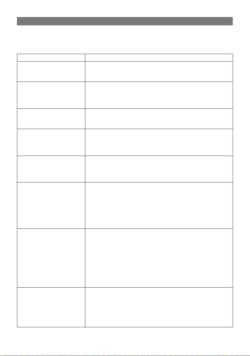
УСТАНОВКА И ОБСЛУЖИВАНИЕ ФИЛЬТРА
Установка
1. Извлечение фильтра
а) Поднимите переднюю панель внутреннего
блока.
b) Извлеките фильтр из прибора (Рис. А)
2. Установите дополнительный фильтр на воздушный фильтр (Рис. Б). Если воздушный
фильтр не получается установить на место,
установите дополнительный фильтр на фронтальную решётку (Рис. В).
3. Установите воздушный фильтр на место и закройте переднюю панель (Рис. Г).
Чистка и обслуживание
Снимайте дополнительный фильтр при чистке воздушного фильтра. Не ис-
пользуйте воду для чистки фильтра с ионами серебра. Сушите фильтр в
солнечной тени, не выжимайте фильтр.
Срок службы
Срок службы дополнительного фильтра составляет 1 год при нормальном
использовании прибора. Заменяйте фильтр с ионами серебра, когда его
поверхность станет чёрной (зелёной).
Внимание:
Дополнительный фильтр и фильтр с ионами серебра могут не входить в
комплектпоставки. Отсутствиеэтихфильтровневлияет наработоспособностьсистемы.
21
Page 22

ПРОВЕРКА ПОСЛЕ УСТАНОВКИ
ОБЛАСТЬ ПРОВЕРКИ ВОЗМОЖНЫЕ НЕПОЛАДКИ
Убедитесь, что все части прибора
надежно закреплены.
Проверьте герметичность трубки
для хладагента.
Проверьте изоляцию. Плохая изоляция приводит к регулярноПроверьте отвод воды.
Проверьте напряжение и частоту
тока в электросети.
Проверьте правильность и надеж-
ность всех соединений.
Прибор должен быть заземлен. Использование незаземленного при-
Проверьте целостность шнура
питания.
Убедитесь, что воздухозаборные
и воздухоотводные отверстия не
заблокированы.
Уточните длину трубки для хладагента.
Прибор может вибрировать и издавать
шум.
Протекание хладагента существенно снижает эффективность работы
прибора.
му образованию конденсата.
Прибор может работать только в электросети 220 - 240 В / 50 Гц.
Неполадки в соединениях могут привести к поломке прибора.
бора может привести к удару электрическим током.
Повреждение шнура питания может
привести к короткому замыканию.
В противном случае эффективность
работы прибора будет существенно
снижена.
Недостаточное или избыточное количество хладагента в системе может
привести к поломке прибора.
ТЕСТИРОВАНИЕ ПРИБОРА
Перед тестированием
1. Не включайте прибор до тех пор, пока полностью не установите его.
2. Убедитесь, что прибор подключен к электросети и заземлен.
3. Заглушки клапанов соединительных труб должны быть открыты.
4. Удалите все упаковочные материалы и материалы, оставшиеся после установки прибора.
Тестирование прибора
1. Включите прибор, нажав кнопку ON/OFF.
2. Используя кнопку MODE, последовательно включите все режимы.
22
Page 23

СПЕЦИФИКАЦИЯ
Функция Охлаждение Обогрев
Рабочее напряжение 220 - 240 В
Частота тока 50 Гц
Производительность
Охлаждающая способность 860 ВТ 770 Вт
Суммарная мощность 1260 Вт 1100 Вт
Сила тока 6,4 А 5,6 А
Воздушный поток 420 м3/ч
Объем обезвоживания 0.8 л/ч
КПД/КС 2,85 Вт / 3,25 Вт
Класс энергоэффективности С
Скорость вентилятора 1060/960/860/760 об/мин
Мощность вентилятора 8 Вт
Радиатор
Диаметр трубок 7 мм
Мощность мотора жалюзи 1,5 Вт
Внутренний блок
Предохранитель PCB 3,15 A
Габариты (Ш/В/Г) 710 X 180 X 250 мм
Вес нетто / Вес брутто 7 / 11 кг
Тип компрессора Роторный
Мощность компрессора 858 Вт
Защита от перегрузки B210-150-241H
Метод ускорения Капиллярный
Внешний блок
Метод запуска Конденсаторный
Диапазон рабочих температур - 15 ~ 46 ºС
Радиатор
Диаметр трубок 7 мм
Скорость вентилятора 950 об/мин
Мощность вентилятора 20 Вт
Воздушный поток 1200 м3/ч
Диаметр лопастей 324 мм
Метод разморозки Автоматический
2450 Вт
(7000 БТЕ/ч)
Алюминиевый с медными труб-
ками
Алюминиевый с медными труб-
ками
2500 Вт
(7000 БТЕ/ч)
23
Page 24

Климатический тип T1
Изоляция I
Защита от влаги IP24
Допустимое избыточное рабочее
давление на стороне нагнетания
Внешний блок
Допустимое избыточное рабочее
давление на стороне всасывания
3,8 МПа
1,2 МПа
Габариты (Ш/В/Г) 720 X 430 X 260 мм
Вес нетто / Вес брутто 25 / 29 кг
Хладагент (тип/масса) R410A / 0.6 г
Длина 5 м
Дополнительная газовая нагрузка 20 г/м
трубки
Внешний диаметр
Соединительный
Максимальное
расстояние
Жидкостная
трубка
Газовая трубка
6 мм
9,52 мм
Высота 5 м
Длина 10 м
В ЦЕЛЯХ УЛУЧШЕНИЯ КАЧЕСТВА ПРОДУКЦИИ ДИЗАЙН И СПЕЦИФИКАЦИЯ МОГУТ
БЫТЬ ИЗМЕНЕНЫ БЕЗ ПРЕДВАРИТЕЛЬНОГО УВЕДОМЛЕНИЯ!
По истечении срока службы товара, необходимо обратиться в сервисный центр за консультацией
по дальнейшей эксплуатации товара. В противном случае дальнейшая эксплуатация может повлечь невозможность нормального использования товара.
Срок службы данного изделия - 3 года с момента продажи
Изготовитель «Эленберг трейд компани лимитед»
Гонг Конг Сьют 18Б, 148 Коннаут Роуд Централ, Гонг Конг
24
Изготовлено в Китае.
Page 25

SPLIT AIR CONDITIONER
SPT-7090
INSTRUCTION MANUAL
Page 26

CONTENT
OPERATING MANUAL ………………………………………………………………………… 27
Introduction …………………………………………………………………………………… 28
Important safeguards ………………………………………………………………………… 28
Unit description ………………………………………………………………………………… 29
Operation of remote control ……………………………………………………………… 30
Special functions ……………………………………………………………………………… 32
Emergency operation ……………………………………………………………………… 34
Clean and care ……………………………………………………………………………… 34
Check before use …………………………………………………………………………… 35
Maintain after use …………………………………………………………………………… 35
Troubleshooting ……………………………………………………………………………… 36
INSTALLATION MANUAL ……………………………………………………………………… 38
Important notices …………………………………………………………………………… 39
Basic requirements for installation position ……………………………………………… 39
Indoor unit installation position selection ………………………………………………… 39
Indoor unit installation position selection ………………………………………………… 39
Safety requirements for electric appliances …………………………………………… 40
Earthing requirements ……………………………………………………………………… 40
Additional safety precautions ……………………………………………………………… 40
Installation dimension diagram …………………………………………………………… 41
Install indoor unit ……………………………………………………………………………… 42
Install outdoor unit …………………………………………………………………………… 43
Installation and maintenance of healthy lter ………………………………………… 45
Check after installation ……………………………………………………………………… 46
Test operation ………………………………………………………………………………… 46
SPECIFICATION ………………………………………………………………………………… 47
26
Page 27

OPERATING MANUAL
27
Page 28

INTRODUCTION
THE DEAR BUYER!
Congratulations, you made a good choice!
You became the owner of ELENBERG production, which offers progressive design
and high quality.
For full and safely usage of the given device, please, closely read the instruction
manual.
IMPORTANT SAFEGUARDS
• When the voltage is very high, the components would be easily damaged, when
the voltage is very low, the compressor vibrates terribly and that the refrigerant
system will be damaged, the compressor and electric components cannot work,
the voltage should be stable; there shouldn’t be big uctuation.
• Be sure to pull out the power plug as the air conditioner not in use for a long time.
Otherwise, the accumulated dusts that may cause over heating or re.
• Never splice the power cord or use an extended cord.
• Don’t block the air intake or outlet vents of both the outdoor and indoor units. It
can decrease the air conditioning capacity or cause a malfunction.
• Don’t leave windows and doors open for a long time while operating the air conditioner. It can decrease the air conditioning capacity.
• The power supply must adopt the special circuit that with air switch protection
and assure it has enough capacity.
The unit will be turned on or off according to your requirement automatically,
please do not turn on or turn off the unit frequently, otherwise disadvantage effect may be caused to the unit.
• When having a burning smell or smoke, please turn off the power supply and
contact with the service center. If the abnormality still exists, the unit may be
damaged, and may cause electric shock or re.
• Keep combustible spray away from the units more than 1 m. It can cause a re
or explosion.
• Don’t attempt to repair the air conditioner by yourself. The wrong repair will lead
to an electric shock or re, so you should contact the service center to repair.
• Please don’t cut off or damage the power cords and control cords. If they are
damaged, please ask the qualied personnel to change them.
• Don’t insert your hands or stick into the air intake or outlet vents.
• Don’t blow the wind to animals and plants directly. It can cause a bad inuence
to them.
• Don’t apply the cold wind to the body for a long time. It can cause the health
problems.
• Don’t use the air conditioner for other purposes, such as drying clothes, preserving foods, etc.
• Splashing water on the air conditioner can cause an electric shock and malfunction.
• Don’t place a space heater near the air conditioner.
Working principle and special functions for cooling
Principle:
Air conditioner absorbs heat in the room and transmit to outdoor and discharged,
so that indoor ambient temperature decreased, its cooling capacity will increase
or decrease by outdoor ambient temperature.
28
Page 29

Anti-freezing function
If the unit is running in COOL mode and in low temperature, there will be frost
formed on the heat exchanger, when indoor heat exchanger temperature decreased below 0 , the indoor unit microcomputer will stop compressor running
and protect the unit.
UNIT DESCRIPTION
1. Power cable
2. Front panel
3. Filter
4. Guide louver
5. Wall pipe
6. Bind tape
7. Connection wire
8. Drainage pipe
9. Remote control
29
Page 30

OPERATION OF REMOTE CONTROL
Names and functions of wireless remote control
Note: Be sure that there are no obstructions between receiver
and remote controller; Don’t drop or throw the remote control;
Don’t let any liquid in the remote control and put the remote
control directly under the sunlight or any place where is very hot.
ON/OFF button
Press this button, the unit will be turned on, press it once more,
the unit will be turned off. When turning on or turning off the
unit, the Timer, Sleep function will be canceled, but the presetting time is still remained.
MODE button
Press this button, Auto, Cool, Dry, Fan
mode can be selected circularly. Auto
mode is default while power on. Under
Auto mode, the temperature will not
be displayed; The initial value is 25 ºC.
SLEEP button
Press this button, Sleep On and Sleep Off can be selected. Af-
ter powered on, Sleep Off is defaulted. After the unit is turned
off, the Sleep function is canceled. After Sleep function set
up, the signal of Sleep will display. In this mode, the time of timer can be adjusted.
Under Fan and Auto modes, this function is not available.
FAN button
Press this button, Auto, Low, Middle, High speed
can be circularly selected. After powered on, Auto
fan speed is default.
Under Dehumidify mode, Low fan speed only can
be set up.
CLOCK button
Press this button, the clock can be set up, signal blink and display. Within 5
seconds, the value can be adjusted by pressing + or - button, if continuously press
this button for 2 seconds above, in every 0.5 seconds, the value on ten place of
Minute will be increased 1. During blinking, repress the Clock button, signal will
be constantly displayed and it denotes the setting succeeded. After powered
on, 12:00 is defaulted to display and signal will be displayed. If there is signal
be displayed that denotes the current time value is Clock value, otherwise is
Timer value.
X-FAN button
Pressing X-FAN button in COOL or DRY mode, the icon is displayed and the in-
door fan will continue operation for 10 minute in order to dry the indoor unit even
though you have turned off the unit.
After energizing, X-FAN OFF is defaulted.
X-FAN is not available in AUTO, FAN or HEAT mode.
Note: X-FAN is the alternative expression of BLOW for the purpose of understand-
ing.
TURBO button
In Cool mode, press this button can turn on or turn off the Turbo function.
After turned on the Turbo function, its signal will be displayed. When switching the
30
Page 31

mode or changing fan speed, this function will be canceled automatically.
+ button
For presetting temperature increasing.
Press this button, can set up the temperature, when unit is on. Continuously press
and hold this button for more than 2 seconds, the corresponding contents will be
changed rapidly, until unpress the button then send the information, ºC is displaying all along. In Auto mode, the temperature can not be set up, but operate this
button can send the signal. Centigrade setting range :16-30; Fahrenheit scale
setting range 61-86.
- button
Presetting temperature can be decreased.
Press this button, the temperature can be set up, continuously press this button
and hold for two seconds, the relative contents can quickly change, until unhold
this button and send the order that the ºC signal will be displayed all the time.
The temperature adjustment is unavailable under the Auto mode, but the order
can be sent by if pressing this button.
LIGHT button
Press this button at unit On or Off status, Light On and Light Off can be set up.
After powered on, Light On is defaulted.
swing up and down button
Press this button, to set up swing angle, which circularly
changes as below:
This is an universal use remote controller.
If remote controller sends the following three kinds of status that
the swing status of main unit will be:
When the guide louver start to swing up and down, if turn off the Swing, the air
guide louver will stop at current position.
which indicates the guide louver swings up and down between that all ve
positions.
TIMER ON button
Timer On setting: Signal “ON” will blink and display, signal will conceal, the
numerical section will become the timer on setting status. During 5 seconds blink,
by pressing + or - button to adjust the time value of numerical section, every press
of that button, the value will be increased or decreased 1 minute. Hold pressing
+ or - button, 2 seconds later, it quickly change, the way of change is:
During the initial 2.5 seconds, ten numbers change in the one place of minute,
then the one place is constant, ten numbers change in the tens place of minute
at 2.5 seconds speed and carry. During 5s blink, press the Timer On button, the
timer setting succeeds. The Timer On has been set up, repress the timer On button, the Timer On will be canceled. Before setting the Timer, please adjust the
Clock to the current actual time.
TIMER OFF button
Once press this key to enter into TIMER OFF setup, in which case the TIMER OFF
icon will blink. The method of setting is the same TIMER OFF as for TIMER ON.
31
Page 32

General operation
1. After powered on, press ON/OFF button, the unit will
start to run. (Note: When it is powered off, the guide
louver of main unit will close automatically.)
2. Press MODE button, select desired running mode, or
press COOL mode to enter into the corresponding operation directly.
3. Pressing +or - button, to set the desired temperature. (It
is unnecessary to set the temp. at AUTO mode.)
4. Pressing FAN button, set fan speed, can select AUTO
FAN, LOW, MID and HIGH.
5. Pressing button, to select the swing.
Optional operation
1. Press SLEEP button, to set sleep.
2. Press TIMER ON and TIMER OFF button, can set the
scheduled timer on
3. Press LIGHT button, to control the on and off of the displaying part of the unit. (This function may be not available for some units)
4. Press TURBO button, can realize the ON and OFF of
TURBO function.
SPECIAL FUNCTIONS
Blow function
This function indicates that moisture on evaporator of indoor unit will be blowed after
the unit is stopped to avoid mould.
1. Having set blow function on: After turning off the unit by pressing ON/OFF button
indoor fan will continue running for about 10 min. at low speed. In this period,
press blow button to stop indoor fan directly.
2. Having set blow function off: After turning off the unit by pressing ON/OFF button,
the complete unit will be off directly.
AUTO RUN
When AUTO RUN mode is selected, the setting temperature will not be displayed on
the LCD, the unit will be in accordance with the room temp. automatically to select
the suitable running method and to make ambient comfortable.
Turbo function
If start this function, the unit will run at super-high fan speed to cool quickly so that
the ambient temp. approachs the preset temp. as soon as possible.
Lock function
Press + and - buttons simultaneously to lock or unlock the keyboard. If the remote
controller is locked, the icon will be displayed on it, in which case, press any button, the mark will icker for three times. If the keyboard is unlocked, the mark will
disappear.
Swing up and down
1. Press swing up and down button continuously more than 2s, the main unit will
swing back and forth from up to down, and then loosen the button, the unit will
stop swinging and present position of guide louver will be kept immediately.
32
Page 33

2. Under swing up and down mode, when the status is switched from off to , if
press this button again 2s later, status will switch to off status directly; if press
this button again within 2s, the change of swing status will also depend on the
circulation sequence stated above.
Switching between Fahrenheit and Centigrade
Under status of unit off, press MODE and - buttons simultaneously to switch ºC and ºF.
Function of defrosting
It indicates: after starting this function by remote controller and the unit has been
under defrost status, If turn off the unit by remote controller, the unit will not stop defrosting until it is nished; if change setting mode by remote controller, the function,
which is set last time, won’t be carried out until defrosting nished.
Operation of this function on or off: If remote controller is under off status, press mode
button and blow button simultaneously in order to enter or cancel this new function.
If the unit is under defrost mode, dual eight position on remote controller will display
H1 in this case, press +/- button, H1 will disappear and setting temp. be displayed.
After remote controller is powered on, the new defrost function will be defaulted to
be closed.
Heating mode
Air conditioner absorbs heat from outdoor and transmits to indoor, in this way to
increase room temperature. This is the heat pump heating principle, its heating capacity will be reduced due to outdoor temperature decrease. If outdoor temperature becomes very low, please operate with other heating equipments.
Defrosting:
• When outdoor temperature is low but high humidity, after a long while running,
frost will form on outdoor unit, at this time, the auto defrosting function will act,
the heat running will stop for 8-10 mins.
• During the auto defrosting, the fan motors of indoor unit and outdoor unit will
stop.
• During the defrosting, the indoor indicator ashes, the outdoor unit may emit vapor. This is due to the defrosting, it isn't malfunction.
• After defrosting nished,the heating will recover automatically.
Anti-cool wind function: In Heat mode, the following three kinds of status, if indoor
heat exchanger hasn't achieve certain temperature that indoor fan motor will not
start, in this way to prevent blowing cool wind (within 3 mins):
1. Heat operation just started up.
2. After Auto defrosting operation is nished
3. Heating under low temperature.
Changing batteries and notices
The wireless remote control adopts two new AAA 1.5 V
dry batteries.
1. Slide the cell cover downward to take out the worn
cells, then change 2 new ones (note to the correct polarity).
2. Cover the cell cover.
NOTE:
• When changing the batteries, do not use the old or different batteries, otherwise, it can cause the malfunction of the wireless remote control.
• If the wireless remote control will not be used for a long
time, please take them out, and don’t let the leakage
33
Page 34

liquid damage the wireless remote control.
• The operation should be in its receiving range.
• It should be placed at where is 1 m away from the TV set or stereo sound sets.
• If the wireless remote control can not operate normally, please take them out,
after 30s later and reinsert, if they cannot normally run, please change them.
EMERGENCY OPERATION
When the wireless remote control is lost or damaged, please use the manual switch,
at this time, it is running in Auto Run mode that will not change the temperature
setting value and fan speed.
The manual switch can be operated as follow:
• At operation: When the unit stopped running, press
ON/OFF button, unit will enter into AUTO RUN mode.
The microcomputer will accord to the room temperature to select the (COOL, HEAT, FAN) mode automatically, to obtain the comfortable effect.
• At stopping: When the unit is running, press the ON/
OFF button of the manual switch, the unit will stop
work.
The code switch can be operated as follow:
• At operation: When the unit is stopped running, adjust the code switch to AUTO, the unit will enter into
AUTO RUN mode. The microcomputer will accord to
the room temperature to select the (COOL, HEAT,
FAN) mode automatically, to obtain the comfortable effect.
• At stopping: When the unit is running, adjusts the
code switch to STOP position, the unit will stop work.
CLEAN AND CARE
Caution:
• Turn power off and pull out the power plug before cleaning air conditioner. Or
it may cause electric shock.
• Never sprinkle water on the indoor unit and the outdoor unit for cleaning because it can cause an electric shock.
• Volatile liquid (e.g. thinner or gasoline) will damage the air conditioner. (So
wipe the units with a dry soft cloth, or a cloth slightly
moistened with water or cleanser.)
Clean the front panel
1. Take off the front panel
Along the direction of arrows to lift the front panel up,
meanwhile to hold both slots of the front panel and
take it out forcibly and then can take it off.
2. Washing
Clean with a soft brush, water and neutral deter-
gent and then dry it. (Note: Before cleaning the unit,
please take down the display box rstly, then to wash
the panel, if the unit has display on the front panel.
Never use the water above 45 ºC to wash the panel,
or it could cause deformation or discoloration.)
34
Page 35

3. Install front panel
Place two supporters of the front panel into the slots,
along the direction of arrows to cover and clasp the
front panel. As show in right gure.
Cleaning the air lters
Note: If dust is much more around the air conditioner,
the air lters should be cleaned many times. After taking
off the lter, don’t touch the n of indoor unit, in order to
avoid hurt your ngers.
1. Take down the air lter
At the slot of surface panel to open an angle, pull the
air lter downward and take it out.
2. Cleaning
To clean the dust adhering to the lters, you can ei-
ther use a vacuum cleaner, or wash them with warm
water (the water with the neutral detergent should
below 45 ºC).
When the lters are very dirty (such as oil stain), and
dry it in the shade.
NOTE: Never use water above 45 ºC to wash, or it can
cause deformation or discoloration. Never partch it
by re, or can cause a re or deformation.
3. Reinsert the lters
Reinsert the lters along
with the arrow head, then
cover the surface panel
and clasp it.
CHECK BEFORE USE
1. Be sure that nothing obstructs the air outlet and intake vents.
2. Check that whether ground wire is properly connected or not.
3. Check that whether the batteries of air conditioner are changed or not.
4. Check that whether the installation stand of the outdoor unit is damaged or
not. If damaged, please contact the dealer.
MAINTAIN AFTER USE
1. Turn main power off.
2. Clean the lter and indoor and outdoor units’ bodies.
3. Repaint the rubiginous place on the outdoor unit to prevent it from spreading.
35
Page 36

TROUBLESHOOTING
Warning:
Do not repair the air conditioner at your discretion. Incorrect repair may cause
electric shock or re, so please contact Authorized Service Center for professional repair.
Following checks prior to contact may save your time and costs.
PROBLEM SOLUTION
Air conditioner does not
run upon immediately
restart after a stop.
Air conditioner blows
out bad smell when it is
initially started.
You may hear “Water
Flowing” noise when the
air conditioner is running.
Sometimes a thin fog
will ow out of the outlet
when air conditioner is
running under cooling
mode.
You may hear a slight
crack when the air
conditioner is started or
stopped.
The unit can not run. • Has the power been shut down?
Cooling efciency is not go• Is Temp. setting suitable?
To protect the air conditioner upon immediate restart
after a stop, the microcomputer controller will delay
the unit for 3 minutes before the air conditioner will
run.
• The air conditioner itself has no bad smell. If any.
It is the bad smell accumulated from environment.
Solution: Clean the air lter.
• If still any problem, the air conditioner shall be
cleaned. (Please contact Authorized Service Center)
When the air conditioner is started, or the compressor
is started or stopped during running or the air conditioner is stopped, sometimes you may hear “hua-hua”
or “di-di-” noise. This is the owing sound of refrigerant
other than fault.
This might occur when indoor temperature and humidity are high. This is because the indoor air is quickly
cooled down.
After a period of time, the fog will disappear with the
decrease of indoor temperature and humidity.
This is the sound of friction caused by expansion of
panel or other parts due to the change of temperature.
• Does power plug come loose from the socket?
• Is the circuit protection device tripped off or not?
• Is voltage higher or lower? (Tested by professionals)
• Is the Timer correctly used?
• Were inlet and outlet vents obstructed?
• Is there too much dusts accumulated and obstructed the lter?
• Are the windows and doors closed?
• Did Fan speed set at low speed?
• Is there any heat sources in the room?
36
Page 37

Wireless remote control is
not available.
If water leakage in the
room.
If water leakage in outdoor unit.
Noise from indoor unit
emitted.
Indoor unit cannot deliver air.
Moisture on air outlet
vent.
Immediately stop all operations and plug out, contact the dealer in following situations:
• There is harsh sound during operation.
• The terrible odors emitted during operation.
• Water is leaking in the room.
• Air switch or protection switch often breaks.
• Carelessy splash water or something into unit.
• There is an abnormal heat in power supply cord and power plug.
• The unit is interfered by abnormal or frequent functions switch over occasionally the controller cannot
operate. At this time, you need to pull out of the
plug, and reinsert it.
• Is it in its receiving range? Or obstructed?
• To check the voltage in wireless remote control inside is charged, otherwise to replace the batteries.
• Whether the wireless remote control is damaged.
• The air humidity is on the high side.
• Condensing water over owed.
• The connection position of indoor unit drainage
pipe is loosed.
• When the unit is running in COOL mode, the pipe
and connection of pipe would be condensed due
to the water cooled down.
• When the unit is running in Auto Defrosting mode,
the ice thawed and owed out.
• When the unit is running in HEAT mode, the water
adhered on heat exchanger dripped off.
• The sound of fan or compressor relay is switching on
or off.
• When the defrosting is started or stop running, it will
sound. That is due to the refrigerant owed to the
reverse direction.
• In dehumidifying mode, sometimes indoor fan will
stop, in order to avoid condensing water be vaporized again, restrain temperature rising.
• In HEAT mode, when the temperature of indoor
heat exchanger is very low, that will stop deliver air
in order to prevent cool air. (Within 3 min)
• In HEAT mode, when the outdoor temperature is low
or high humidity, there are much frost be formed
on the outdoor heat exchanger, that the unit will
automatically defrost, indoor unit stop blowing air
for 3-12 mins. During the defrosting, there is water
owing out or vapor be produced.
If unit is running under the high humidity for a long
time, the moisture will be condensed on the air outlet
grill and drip off.
37
Page 38

INSTALLATION MANUAL
38
Page 39

IMPORTANT NOTICES
1. The unit installation work must be done by qualied personnel according to the
local rules and this manual.
2. If the air conditioner has not plug, directly connect it into the xed circuit, a
breaker should be installed in the xed circuit. all pole of this breaker should be
switching off and the distance of the contact should be at least 3 mm.
BASIC REQUIREMENTS FOR INSTALLATION POSITION
Install in the following place may cause malfunction. If it is unavoidable contact
with service center please:
• Place where strong heat sources, vapors, ammable gas or volatile object are
emitted.
• Place where high-frequency waves are generated by radio equipment, welders and medical equipment.
• Place where a lot of salinities such as coast exists.
• Place where the oil (machine oil) is contained in the air.
• Place where a sulfured gas such as the hot spring zones is generated.
• Other place with special circumstance.
INDOOR UNIT INSTALLATION POSITION SELECTION
1. The air inlet and outlet vent should be far from the obstruction, make sure that
the air can be blown through the whole room.
2. Select a position where the condensing water can be easily drained out, and
the place is easily connected for outdoor unit.
3. Select a location where the children can not reach.
4. Can select the place where is strong enough to withstand the full weight and
vibration of the unit. And will not increase the noise.
5. Be sure to leave enough space to allow access for routine maintenance. The
height of the installed location should be 230 cm or more from the oor.
6. Select a place about 1m or more away from TVset or any other electric appliances.
7. Select a place where the lter can be easily taken out.
8. Make sure that the indoor unit installation should accord with installation dimension diagram requirements.
OUTDOOR UNIT INSTALLATION POSITION SELECTION
1. Select a location from which noise and outow air emitted by unit will not inconvenience neighbors, animals, plants.
2. Select a location where there should be sufcient ventilation.
3. Select a location where there should be no obstructions cover the inlet and
outlet vent.
4. The location should be able to withstand the full weight and vibration of the
outdoor unit and permit safe installation.
5. Select a dry place, but do not expose under the direct sunlight or strong wind.
6. Make sure that the outdoor unit installation dimension should accord with installation dimension diagram, convenient for maintenance, repair.
7. The height difference of connecting the tubing within 5m, the length of connecting the tubing within 10 m.
8. Select a place where it is out of reach for the children.
39
Page 40

9. Select a place where will not block the passage and do not inuence the city
appearance.
SAFETY REQUIREMENTS FOR ELECTRIC APPLIANCES
1. The power supply should be used the rated voltage and AC exclusive circuit,
the power cable diameter should be satised.
2. Don’t drag the power cable emphatically.
3. It should be reliably earthed, and it should be connected to the special earth
device, the installation work should be operated by the professional.
The air switch must have the functions of magnetic tripping and heat tripping,
in order to protect the short circuit and overloading.
4. The min. distance from the unit and combustive surface is 1.5 m.
Note:
• Make sure that the Live wire or Zero line as well as the earth wire in the family
power socket can not be wrong connected, there should be reliable and no
short circuit in the diagram.
• Wrong connection may cause re.
EARTHING REQUIREMENTS
1. Air conditioner is type I electric appliance, thus please do conduct reliable
earthing measure.
2. The yellow-green two-color wire in air conditioner is earthing wire and cannot
be used for other propose. It cannot be cut off and be x it by screw, otherwise
it would cause electric shock.
3. The earth resistance should accord to the National Criterion.
4. The user power must offer the reliable earthing terminal. Please don’t connect
the earthing wire with the following place:
A. Tap water pipe.
B. Gas pipe.
C. Contamination pipe.
D. Other places that professional personnel consider them unreliable.
ADDITIONAL SAFETY PRECAUTIONS
1. The connection method of unit and power cable as well as the interconnect
method of each isolated component should refer to the circuit diagram stick on
the unit.
2. The model of the blown fuse and rated value should refer to the silk-screen on
the controller or fuse sleeve.
3. The appliance shall be installed in accordance with national wiring regulations.
4. This appliance is not intended for use by persons (including children) with reduced physical, sensory or mental capabilities, or lack of experience and
knowledge, unless they have been given supervision or instruction concerning
use of the appliance by a person responsible for their safety.
5. Children should be supervised to ensure that they do not play with the appliance.
40
Page 41

INSTALLATION DIMENSION DIAGRAM
41
Page 42

INSTALL INDOOR UNIT
Install the rear panel
1. Always mount the rear panel horizontally. As the water drainage pipe at the
left, when adjusting the rear panel, this side should not be too high; the right
side should be slightly high.
2. Fix the rear panel on the selected location
3. Be sure that the rear panel has been xed rmly
enough to withstand the
weight of an adult of 60
kg, furthermore, the weight
should be evenly shared by
each screw.
Install the piping hole
1. Make the piping hole in the wall at a slight downward
slant to the outdoor side.
2. Insert the piping-hole sleeve into the hole to prevent
the connection piping and wiring from being damaged when passing through the hole.
Install the water drainage pipe
1. For well draining, the drain hose should be placed at
a downward slant.
2. Do not wrench or bend the drain hose or ood its end
by water.
3. When the long drainage hose passing through indoor, should wrap the insulation materials.
Connect indoor and outdoor electric wires
1. Open the front panel upwardly.
2. Screw off the xing screw of cover plate and screw off cover plate.
3. Put the power connection cable through the back of indoor unit wire hole and
take it out.
4. All the wiring should be connected according to the circuit diagram on the
unit.
5. Put the power connection cable the section, which with sheath into wire groove,
and cover the cover plate, screw on the xing screw, tighten the connection
wire.
6. Cover the front panel cover.
7. For the cooling and heating unit, signal control wire can be passed through the
connection of connector and indoor unit, and use the wire clip that is under the
body case, tighten the signal control wire.
NOTE: When connecting the electric wire if the wire length is not enough, please
contact with the authorized service shop to buy a exclusive electric wire that is
long enough and the joint on the wire are not allowed.
• The electric wiring must be correctly connected, wrong connection may cause
spare parts malfunction.
• Tighten the terminal screw in order to prevent loose.
• After tighten the screw, slightly pull the wire and conrm whether is it rm or
not.
42
Page 43

• If the earth wire is wrong connection, that may cause electric shock.
• The cover plate must be xed, and tighten the connection wire, if it is poor installed, that the dust, moisture may enter in or the connection terminal will be
affected by outside force, and will cause re or electric shock.
• Leakage circuit-breaker and air switch of correct capacity must be installed.
Install the indoor unit
The piping can be lead out from right, right rear, left, left rear.
1. When routing the piping and wiring from
the left or right side of indoor unit, cut off the
tailings from the chassis in necessary (show
in Fig.2)
1). Cut off the tailings 1 when routing the
wiring only;
2). Cut off the tailings 1 and tailings 2 when
routing both the wiring and piping.(or
1,2,3);
2. Take out the piping from body case, wrap
the piping electric wire, water pipe with
tape and put them through the piping hole
(As show in Fig. 3)
3. Hang the mounting slots of the indoor unit
on the upper tabs of the rear panel and
check if it is rm enough. (As show in Fig.4)
Install the connection pipe
1. Align the center of the piping are with the relevant valve.
2. Screw in the are nut by hand and then tighten
the nut with spanner and torque wrench refer
to the following.
Tightening torque table:
Hex nut diameter Tightening torque (N•m)
Ø 6 15 ~ 20
Ø 9.52 31 ~ 35
Ø 12 50 ~ 55
Ø 16 60 ~ 65
Ø 19 70 ~ 75
NOTE: Firstly connect the connection pipe to indoor unit, then to outdoor unit;
pay attention to the piping bending, do not damage the connection pipe; the
joint nut couldn’t tighten too much, otherwise it may cause leakage.
INSTALL OUTDOOR UNIT
Electric Wiring
1. Disassemble handle of right side plate or front side plate of outdoor unit.
2. Take off wire clamp, connect and x power connect cord to terminal of line
bank.
Wiring should t that of indoor unit.
3. Fix the power connection cable with wire clamp, for cooling and heating unit,
43
Page 44

then use the wire clamp to x the signal control wire, then connect the corresponding connector.
4. Ensure if wire has been xed well.
5. Install handle or front side plate.
NOTE:
• Wrong wiring may cause spare parts malfunction.
• After the cable xed, make sure there should be a free space between the
connection and xing place on the lead wire.
Air purging and leakage test
1. Connect charging hose of manifold valve to
charge end of low pressure valve (both high/
low pressure valves must be tightly shut).
2. Connect joint of charging hose to vacuum
pump.
3. Fully open handle of Lo manifold valve.
4. Open the vacuum pump to evacuate. At the
beginning, slightly loosen joint nut of low pressure valve to check if there is air coming inside.
(If noise of vacuum pump has been changed,
the reading of multimeter is 0) Then tighten the nut.
5. Keep evacuating for more than 15 mins and make sure the reading of multimeter is -1.0 x 10⁵ Pa (-76 cmHg).
6. Fully open high/low pressure valves.
7. Remove charging hose from charging end of low pressure valve.
8. Tighten bonnet of low-pressure valve. (As shown in Fig. 5)
Leak hunting
Use soap water or leak hunting meter to check
whether the joints is leak.
Outdoor condensation drainage
When the unit is heating, the condensing water
and defrosting water can be drained out reliably through the drain hose.
Installation: Install the outdoor drain elbow in
ø25 hole on the base plate, and joint the drain
hose to the elbow, so that the wastewater
formed in the outdoor unit can be drained out
to a proper place.
44
Page 45

INSTALLATION AND MAINTENANCE OF HEALTHY FILTER
1. Forcibly pull the panel for a specic angle from
the two ends of the front panel according to the
arrow direction. Then pull the air lter downwards
to remove it. (See Fig. a)
2. Mount the healthy lter onto the air lter, (as
shown in Fig. b). If the air lter cannot be installed,
please mount the healthy lter on the front case.
(as shown in Fig. c).
3. Mount the air lter properly along the arrow direction in Fig. d, and then close the panel cover.
Cleaning and Maintenance
Take out the healthy lter before cleaning and reinstall it after cleaning ac-
cording to the installation instruction. Pay special attention to that silver ion lter
can’t be cleaned with water, while active carbon, photocatalyst, low temperature conversion (LTC) catalyst, formaldehyde eliminator, catechin or mite killing
lter can, but can’t with brush or hard things. Dry it in the shade or sun after
cleaning, but not by wiping.
Service Life
The healthy lter commonly has its usage lifetime for one year under normal con-
dition. As for silver ion lter, it is invalid when its surface becomes black (green).
This supplementary instruction is provided for reference to the unit with healthy
lter. If the graphics provided herein is different from the physical goods, the latter one shall prevail. The quantity of healthy lters shall be based on the actual
delivery.
45
Page 46

CHECK AFTER INSTALLATION
Items to be checked Possible malfunction
Has it been xed rmly? The unit may drop, shake or emit noise.
Have you done the refrigerant
leakage test?
Is heat insulation sufcient? It may cause condensation and dripping.
Is water drainage well? It may cause condensation and dripping.
Is the voltage in accordance with
the rated voltage marked on the
nameplate?
Is the electric wiring and piping
connection installed correctly and
securely?
Has the unit been connected to a
secure earth connection?
Is the power cord specied? It may cause electric malfunction or dam-
Is the inlet and outlet been covered?
Has the length of connection pipes
and refrigerant capacity been
recorded?
It may cause insufcient cooling (heating)
capacity.
It may cause electric malfunction or damage the part.
It may cause electric malfunction or damage the part.
It may cause electrical leakage.
age the part.
It may cause insufcient cooling (heating)
capacity.
The refrigerant capacity is not accurate.
TEST OPERATION
Before test operation
1. Do not switch on power before installation is nished completely.
2. Electric wiring must be connected correctly and securely.
3. Cut-off valves of the connection pipes should be opened.
4. All the impurities such as scraps and thrums must be cleared from the unit.
Test operation method
1. Switch on power, press “ON/OFF” button on the wireless remote control to start
the operation.
2. Press MODE button, to select the COOL, HEAT, FAN to check whether the operation is normal or not.
46
Page 47

SPECIFICATION
FUNCTION COOLING HEATING
Rated Voltage 220 - 240 V
Rated Frequency 50 Hz
Total Capacity (W/Btu/h)
Power Input (W) 860 770
Rated Input (W) 1260 1100
Rated Current (A) 6.4 5.6
Air Flow Volume (m3/h) (H/M/L) 420
Dehumidifying Volume (l/h) 0.8
EER/C.O.P. (W/W) 2.85 / 3.25
Energy Class C
Fan Motor Speed (r/min) (H/M/L) 1060/960/860/760
Output of Fan Motor (w) 8
Evaporator Aluminum n-copper tube
Indoor unit
Pipe Diameter (mm) 7
Output of Swing Motor (W) 1.5
Fuse (A) PCB 3.15 A
Dimension (W/H/D) ( mm) 710 X 180 X 250
Net Weight /Gross Weight (kg) 7/11
Compressor Type Rotory
Compressor Power Input(W) 858
Overload Protector B210-150-241H
Throttling Method Capillary
Outdoor unit
Starting Method Capacitor
Working Temp Range (°C) -15 ~ 46
Condenser Aluminum n-copper tube
Pipe Diameter (mm) 7
Rows-Fin Gap(mm) 1-1.4
Fan Motor Speed (rpm) 950
Output of Fan Motor (W) 20
Air Flow Volume of Outdoor Unit 1200
Fan Type-Piece Axial fan –1
Fan Diameter (mm) 324
Defrosting Method Auto defrost
2450 W
(7000 Btu/h)
2500 W
(7000 Btu/h)
47
Page 48

Climate Type T1
Isolation I
Moisture Protection IP24
Permissible Excessive Operating Pres-
Outdoor unit
sure for the Discharge Side (MPa)
Permissible Excessive Operating Pres-
sure for the Suction Side (MPa)
3.8
1.2
Dimension (W/H/D) ( mm) 720 X 430 X 260
Net Weight /Gross Weight (kg) 25/29
Refrigerant Charge (kg) R410A / 0.6
Length (m) 5
Gas additional charge (g/m) 20
Outer Diameter
Connection pipe
Max Distance
Liquid Pipe
(mm)
Gas Pipe
(mm)
Height (m) 5
Length (m) 10
6
9.52
DESIGN AND SPECIFICATIONS ARE SUBJECT TO CHANGE WITHOUT NOTICE!
Address to service center for consultation, when the service life of product has expired. Otherwise the further
operation can entail impossibility of normal use of the product.
Service life of the given product - 3 years from the moment of sale
48
 Loading...