

Electrolux EXH09RLEWE User Manual [dk]
EPH09MLIW
EPH12MLIW
EXH09RLEW
EXH12RLEW
EN SPLIT INVERTER
HEAT PUMP
DA SPLIT INVERTER
VARMEPUMPE
SV SPLIT INVERTER
VÄRMEPUMP
NO SPLITTINVERTER
VARMEPUMPE
FI INVERTTERI
LÄMPÖPUMPPU
USER MANUAL
BRUGERVEJLEDNING
BRUKSANVISNING
BRUKSANVISNING
OHJEKIRJA
2
26
48
70
92
2 www.electrolux.com
TABLE OF CONTENTS
Safety precautions .................................................................................................... 3
Description................................................................................................................ 6
Remote control ......................................................................................................... 6
Cleaning and maintenance...................................................................................... 12
Troubleshooting....................................................................................................... 13
Operation tips ......................................................................................................... 15
Installation............................................................................................................... 16
Health filter.............................................................................................................. 25
WE’RE THINKING OF YOU
Thank you for purchasing an Electrolux appliance. You’ve chosen a product that brings with
it decades of professional experience and innovation. Ingenious and stylish, it has been
designed with you in mind. So whenever you use it, you can be safe in the knowledge that
you’ll get great results every time.
Welcome to Electrolux.
Visit our website for:
Get usage advice, brochures, trouble shooter, service information:
www.electrolux.com
Register your product for better service:
www.electrolux.com/productregistration
Buy Accessories, Consumables and Original spare parts for your appliance:
www.electrolux.com/shop
CUSTOMER CARE AND SERVICE
We recommend the use of original spare parts.
When contacting Service, ensure that you have the following data available.
The information can be found on the rating plate. Model, PNC, Serial Number.
Warning / Caution-Safety information
General information and tips
Environmental information
Subject to change without notice.

SAFETY PRECAUTIONS
t
Read the manual carefully before operation.
t
Keep the manual for further reference.
t
This appliance can be used by children aged from 8 years and
above and persons with reduced physical, sensory or mental
capabilities or lack of experience and knowledge if they have
been given supervision or instruction concerning use of the
appliance in a safe way and understand the hazards involved.
Children shall not play with the appliance. Cleaning and user
maintenance shall not be made by children without supervision.
t
If something abnormal occurs (e.g. unpleasant smells of
burning), disconnect the unit from the power supply and
contact an authorised service centre. If the abnormality
remains, the air conditioner may be damaged or even cause
electric shock or fire.
t
Before cleaning or maintenance, switch off the unit and
disconnect the unit from the power supply. If the unit is
connected to a fuse box, remove the fuse.
t
If the supply cord is damaged, it must be replaced by the
manufacturer, its service agent or similarly qualified persons
in order to avoid a hazard.
t
Do not use an unspecified mains cord to prevent electric
shock or fire.
t
The unit must be installed according to national regulations
for electrical safety. Incorrect wiring can lead to over heat or
fire in the cable, the plug or the electrical outlet.
t
Do not switch on and off the unit frequently.
t
If the voltage is too high, electrical elements will be damaged
easily, If the voltage too low, the compressor will vibrate
fiercely and damage the cooling system or the compressor.
Electrical components cannot be operated.
t
Make sure that the unit is properly grounded to prevent
electric shock.
ENGLISH 3

4 www.electrolux.com
SAFETY PRECAUTIONS
Do not attempt to repair the unit yourself to prevent electric
shock or fire. Have the unit repaired by an authorised service
centre.
Keep combustible materials at least 1 m from the unit to
prevent fire or explosion.
Install the outdoor unit firmly to prevent personal injury.
Do not stand on the outdoor unit. Do not place heavy things
on the outdoor unit.
Do not block the air inlet or the air outlet.
Do not splash water on the unit to prevent electric shock.
Do not operate the unit with wet hands to prevent electric
shock.
Do not insert your hands or objects into the air inlet or the air
outlet.
Do not expose animals or plants directly to the air flow.
Do not expose yourself to cold air directly for a long time.
Do not use the unit for any other purpose, such as preserving
food or drying clothes.
Select the most appropriate temperature to save electric
energy.
Do not keep windows and doors open for a long time during
operation.
To change the airflow direction, use remote control to adjust
the horizontal and vertical airflow direction.
Do not use fire or hair dryer to dry the filter to avoid
deformation or fire hazard.
Keep heat sensible material at least 1 meter far from
air flow to prevent damaging.
SAFETY PRECAUTIONS
t
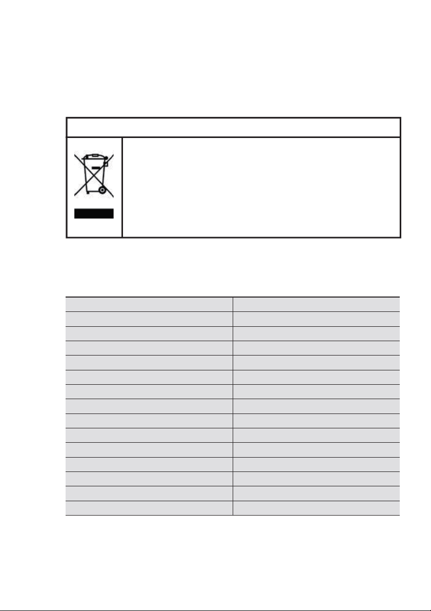
Do not dispose this product as unsorted municipal waste.
Collection of such waste separately for special treatment is
necessary.
This marking indicates that this product should not be disposed
with other household wastes throughout the EU. To prevent
possible harm to the environment or human health from
uncontrolled waste disposal, recycle it responsibly to promote the
sustainable reuse of material resources. To return your used
device, please use the return and collection systems or contact the
retailer where the product was purchased. They can take this
product for environmental safe recycling.
You can also get this manual through your local distributor or
by visiting our website.
Please find the Electrolux web addresses to your local country from below table.
Country Website address Country Website address
Albania www.electrolux.al
Austria www.electrolux.at
Belgium www.electrolux.be
Bulgaria www.electrolux.bg
Croatia www.electrolux.hr
Czech Republik www.electrolux.cz
Denmark www.electrolux.dk
Finland www.electrolux.fi
France www.electrolux.fr
Germany www.electrolux.de
Greece www.electrolux.gr
Hungary www.electrolux.hu
Italy www.electrolux.it
Luxembourg www.electrolux.lu
Please visit www.electrolux.com for more information.
ENGLISH 5
Correct Disposal of this product
Netherlands www.electrolux.nl
Norway www.electrolux.no
Poland www.electrolux.pl
Portugal www.electrolux.pt
Romania www.electrolux.ro
Serbia www.electrolux.rs
Slovakia www.electrolux.sk
Slovenia www.electrolux.sl
Spain www.electrolux.es
Sweden www.electrolux.se
Switzerland www.electrolux.ch
Turkey www.electrolux.com.tr
UK & Ireland www.electrolux.co.uk
6 www.electrolux.com
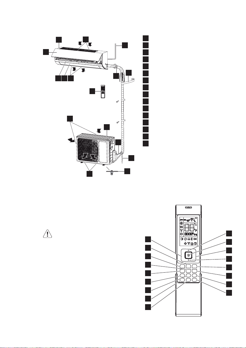
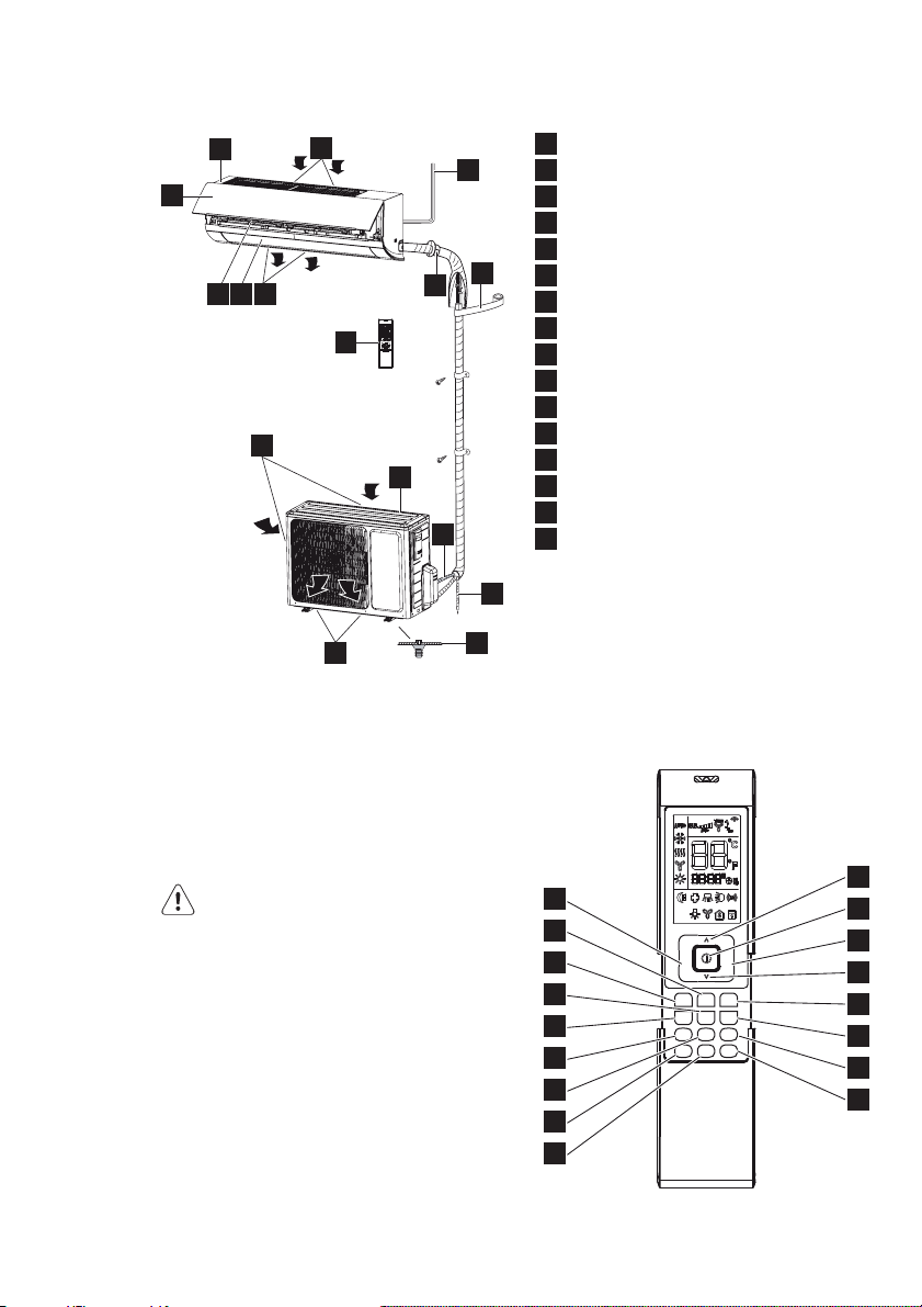
DESCRIPTION
1
9
10 11 3
1
2
7
13
12
8
4
5
14
Indoor unit
2
Air inlet (indoor unit)
3
Air outlet (indoor unit)
4
Outdoor unit
5
Air inlet (outdoor unit)
6
Air outlet (outdoor unit)
7
Mains cord
8
Remote control
9
Front panel
10
Filter
11
Horizontal louvre
12
Wall pipe
13
Binding tape
14
Connection pipe
15
Drain hose
16
Drain connector
15
16
6
16
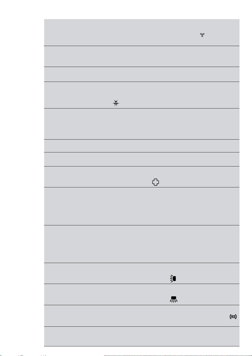
REMOTE CONTROL
The remote control can be used for
different models. Depending on the
model, some functions on the remote
control might not be available.
CAUTION
r© $O©NOT©DROP©OR©THROW©THE©REMOTE©
control.
r© $O©NOT©POUR©LIQUID©ONTO©THE©REMOTE©
control.
r© $O©NOT©EXPOSE©THE©REMOTE©CONTROL©TO©
direct sunlight.
r© $O©NOT©PLACE©THE©REMOTE©CONTROL©IN©
areas where it is very hot.
NOTE
r© -AKE©SURE©THAT©THERE©ARE©NO©OBJECTS©
between the signal transmitter on the
remote control and the signal receiver
of the unit.
18
24
29
32
30
25
31
22
23
20
17
Fan
Mode
Swing-
Slee
Turbo
V
p
ION
Swing-H
Quiet
Filter
Timer
X-Fan
I Feel
On
Timer
Clock
Light
Off
19
21
33
26
27
28
ENGLISH 7
Explanation of buttons
Nr. Button Explanation
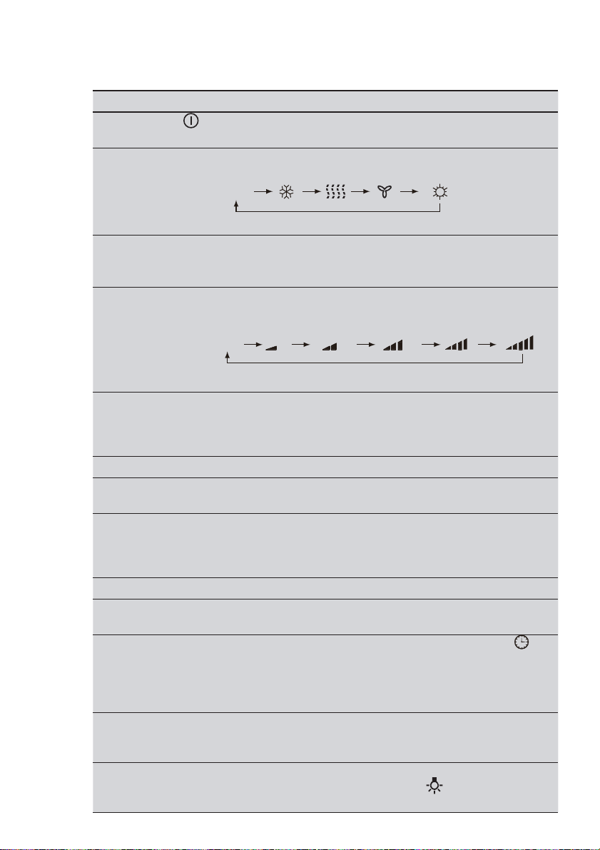
17 ON/OFF Press the button to switch on the unit. Press the button again
18 MODE Press the button to set the operation mode: AUTO, COOL,
19 FAN Press the button to set the fan speed: AUTO, LOW, MEDIUM
20 UP ^ Press the button to increase the temperature. Keep the
21 DOWN v Press the button to decrease the temperature. Keep the
22 CLOCK
23 LIGHT Press the button to switch the display of the indoor unit on or
to switch off the unit.
DRY, FAN and HEAT. Default setting: AUTO.
AUTO
AUTO COOL DRY FAN HEAT
In the AUTO mode, the temperature is not shown. In HEAT
mode, the initial value is 28 °C (82 °F). In other modes, the
initial value is 25 °C (77 °F).
LOW, MEDIUM, MEDIUM HIGH and HIGH. Default setting:
AUTO. In the DRY mode, only LOW can be set.
AUTO
Auto Low Medium-low Medium Medium-high High
button pressed for two seconds to accelerate the process.
Release the button to set the temperature and send the order
that the °C/°F signal will be displayed constantly.
Temperature range: 16-30 °C (61-86 °F).
In AUTO mode, the temperature cannot be set. If you press
the UP or DOWN button, a beep will sound.
button pressed for two seconds to accelerate the process.
Release the button to set the temperature and send the order
that the °C/°F signal will be displayed constantly.
Temperature range: 16-30 °C (61-86 °F).
In AUTO mode, the temperature cannot be set, but the order
can be sent by pressing the button.
Press the button to set the clock. If the clock symbol ” ”
blinks, press the UP or DOWN button to set the time. Keep
the button pressed for two seconds to accelerate the
process. Press the CLOCK button again to set the clock.
The clock symbol stops blinking.
After battery replacement, “12:00 PM” will be shown. If the
clock symbol is visible, the actual time will be shown. If the
clock symbol is not visible, the timer will be shown.
off. When switch on, the light symbol ” ” will be showed.
Default setting: OFF.
8 www.electrolux.com
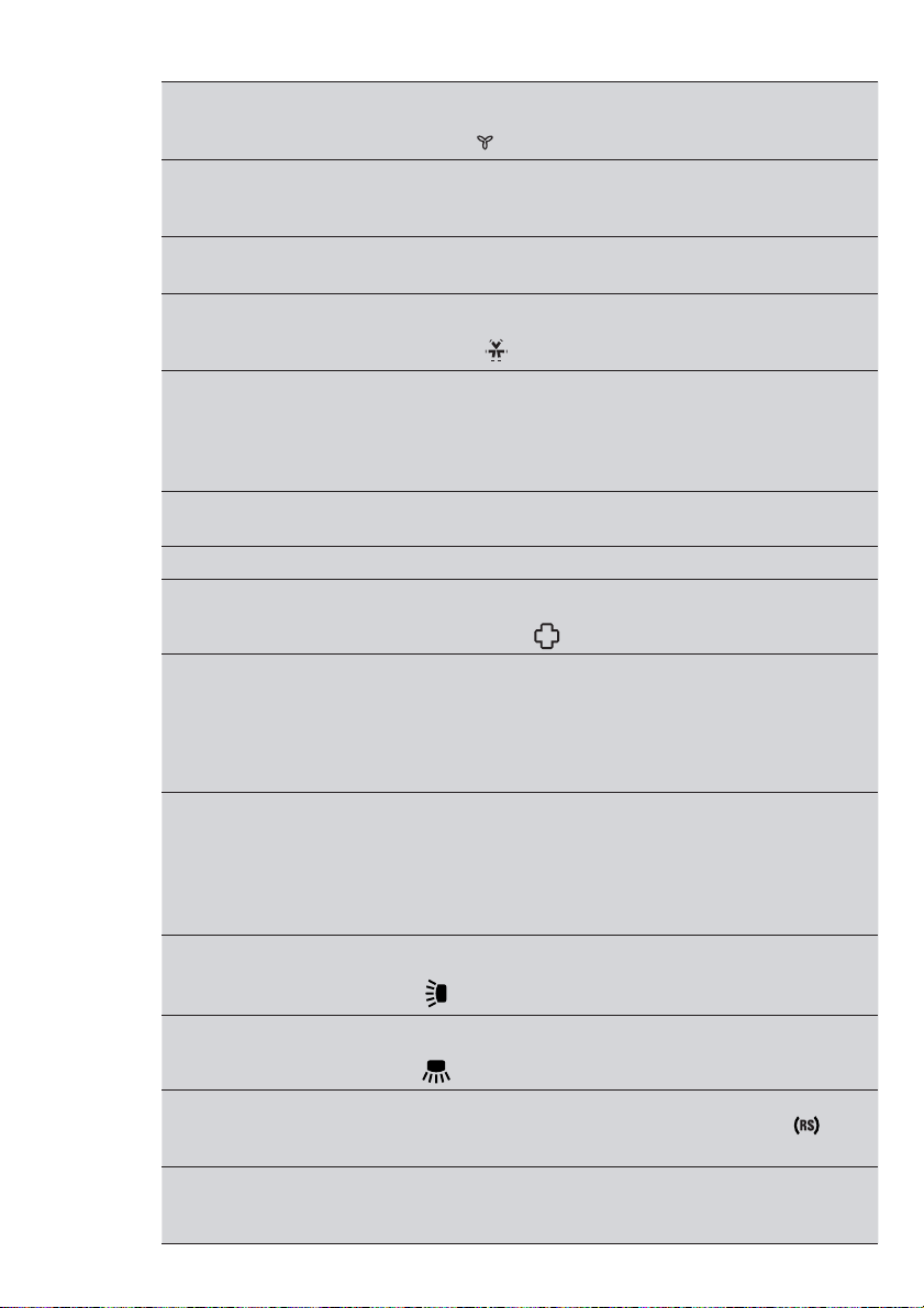
24 TURBO In COOL or HEAT mode, press the button to enable or
disable the turbo function. If the turbo function is enabled, the
turbo symbol ” ” will be shown. Default setting: OFF.
TURBO
If the turbo function is enabled, the unit will operate at turbo
speed to cool or heat rapidly so that the ambient temperature
approaches the set temperature as soon as possible.
If the operation mode or the fan speed is changed, the turbo
symbol will not be shown.
25 X-FAN In COOL or DRY mode, press the button to enable or disable
the X-FAN function. If the X-FAN function is enabled, the
X-FAN symbol ” ” will be shown. Default setting: OFF.
If the X-FAN function is enabled, the indoor fan will continue
operation at low speed for 2 minutes after switching off
the unit. This function prevents the possible condensation
on cold parts of the indoor unit. Press the X-FAN button to
switch off the unit during the process.
If the X-FAN function is disabled, the unit will be switched off
immediately.
In AUTO, FAN or HEAT mode, X-FAN is not available.
26 ION-FILTER Press the button to enable or disable the operation of the
health filter. If the ION-FILTER function is enabled, the
ION-FILTER symbol ” ” will be shown.
27 TIMER ON
Press the button to set the timer function for switching on the
unit. If the TIMER ON symbol ”ON” blinks, press the UP or
DOWN button to set the time. Keep the button pressed for
two seconds to accelerate the process. Press the button to
set the timer. Default setting: 8:00 AM (12-hour mode). Press
the button again to cancel the timer function.
28 TIMER OFF Press the button to set the timer function for switching off the
unit. If the TIMER OFF symbol ”OFF” blinks, press the UP or
DOWN button to set the time. Keep the button pressed for
two seconds to accelerate the process. Press the button to
set the timer. Default setting: 5:00 PM (12-hour mode). Press
the button again to cancel the timer function.
29 SWING-V Press the button to enable or disable the vertical swing
function. If the SWING-V function is enabled, the SWING-V
symbol ” ” will be shown.
30 SWING-H Press the button to enable or disable the horizontal swing
function. If the SWING-H function is enabled, the SWING-V
symbol ” ” will be shown.
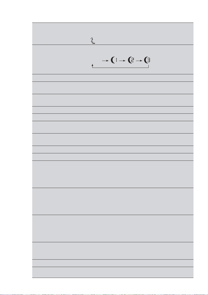
31 I FEEL Press the button to enable or disable the I FEEL function.
If the I FEEL function is enabled, the I FEEL symbol ” ” will
be shown.
If the I FEEL symbol is enabled, the remote control will send
the ambient temperature to the main unit every 10 minutes or
when you press one of the buttons.
ENGLISH 9
32 QUIET Press the button to enable or disable the QUIET function.
If the QUIET function is enabled, the indoor fan operates at
ultra-low speed so that the indoor noise is low, and the QUIET
symbol ” ” will be shown.
33 SLEEP Press the button to select (SLEEP 1, SLEEP 2, SLEEP 3 or
SLEEP CANCEL). Default setting: SLEEP CANCEL.
No symbol
SLEEP CANCEL SLEEP 1 SLEEP 2 SLEEP 3
SLEEP 1 In COOL and DRY mode:
Sleep status after 1 hour of operation: The temperature will
increase by 1 °C.
Sleep status after 2 hours of operation: The temperature will
increase by 2 °C.
After this time the unit continues to use the new temperature.
In HEAT mode:
Sleep status after 1 hour of operation: The temperature will
decrease by 1 °C.
Sleep status after 2 hours of operation: The temperature will
decrease by 2 °C.
After this time the unit continues to use the new temperature.
SLEEP 2 In COOL mode:
If you set a temperature of 16-23 °C, the temperature will
increase by 1 °C every hour. After 3 °C, the temperature will
be maintained. After 7 hours, the temperature will decrease
by 1 °C. After this time the unit continues to use the new
temperature.
If you set a temperature of 24-27 °C, the temperature will
increase by 1 °C every hour. After 2 °C, the temperature will
be maintained. After 7 hours, the temperature will decrease
by 1 °C. After this time the unit continues to use the new
temperature.
If you set a temperature of 28-29 °C, the temperature will
increase by 1 °C every hour. After 1 °C, the temperature will
be maintained. After 7 hours, the temperature will decrease
by 1 °C. After this time the unit continues to use the new
temperature.
If you set a temperature of 30 °C, the temperature will
decrease by 1 °C after 7 hours. After this time the unit
continues to use the new temperature.
In HEAT mode:
If you set a temperature of 16 °C, the unit will operate at this
temperature.
10 www.electrolux.com
SLEEP 3 The user-dejned behaviour mode. The time on remote control
If you set a temperature of 17-20 °C, the temperature will
decrease by 1 °C every hour. After 1 °C, the temperature will
be maintained.
If you set a temperature of 21-27 °C, the temperature will
decrease by 1 °C every hour. After 2 °C, the temperature will
be maintained.
If you set a temperature of 28-30 °C, the temperature will
decrease by 1 °C every hour. After 3 °C, the temperature will
be maintained.
will show “1hour”. The temperature to use after 1 hour will
blink.
Press the UP and DOWN buttons to set the desired
temperature. Press the TURBO button again to conjrm.
The value "1hour" will increase to the value "2hours",
"3hours" or ”8hours”. In each step the corresponding
temperature will blink.
Repeat the above (2 3) operation for the "2hours", "3hours"
and ”8hours” steps.
Sleep3: Display the set temperatures:
Select SLEEP 3 without changing temperature. Press the
TURBO button to conjrm.
Note: The above setting or enquiry procedure terminates if
no button is pressed for 10 seconds. The ON/OFF button,
the MODE button and the SLEEP button also terminate the
setting or enquiry procedure.
General operation
1. Disconnect the unit from the power
supply.
2. Press the ON/OFF button to start
the unit.
3. Press the MODE button to set the
operation mode.
4. Press the UP and DOWN buttons
to set the temperature. (Note: It is
unnecessary to set the temperature
in AUTO mode.)
5. Press the FAN button to set the fan
speed.
6. Press the SWING-H and SWING-V
buttons to set the swing.
Optional operation
1. Press the SLEEP button to enable
or disable the sleep mode.
2. Press the TIMER ON and TIMER
OFF buttons to enable or disable the
timer function.
3. Press the LIGHT button to turn
on or to turn off the display of the
indoor unit.
4. Press the TURBO button to enable
or disable the turbo function.
Special functions
AUTO mode
The temperature will not be displayed.
The unit automatically sets the operation
mode.
Locking/unlocking the remote control
Simultaneously press the SWING-V
button and the ION-FILTER button to
lock or unlock the remote control. If
the remote control is locked, the LOCK
symbol ” ”will be shown. Press any
button to make the LOCK symbol blink
ENGLISH 11
3 times and unlock the remote control.
If the remote control is unlocked, the
LOCK symbol will not be shown.
Celsius (°C) ~ Fahrenheit (°F)
If the unit is switched off, simultaneously
press the SWING-H button and the
ION-FILTER button to switch between
Celsius (°C) and Fahrenheit (°F).
Energy-saving function
In COOL mode, simultaneously press
the ION-FILTER button and the CLOCK
button to enable or disable the energysaving function. The display shows ”SE”.
8 °C heating function
In HEAT mode, simultaneously press
the ION-FILTER button and the CLOCK
button to enable or disable the 8 °C
heating function. The display shows
”8 °C” (”46 °F”). The unit starts to heat
when the temperature drops below
8 °C. Fan Speed will be AUTO and
cannot be changed.
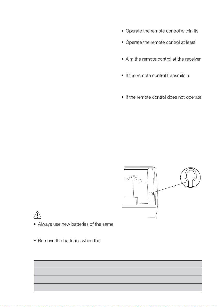
Replacng the batteries
The remote control operates with two
1.5V AAA batteries.
1. Open the battery compartment.
2. Remove the old batteries.
3. Insert the new batteries. Make sure
that the positive (+) and negative (-)
markings on the batteries match the
positive (+) and negative (-) markings
on the battery compartment.
4. Close the battery compartment.
NOTE
transmitting and receiving range.
1 m away from your TV set or stereo
sound set.
of the main unit to improve the
receiving sensitivity of the main unit.
signal, the transmitting symbol will
blink for 1 second. The bell will ring if
the main unit receives the signal.
normally, remove the batteries
and insert them again 30 seconds
later. If the remote control still does
not operate normally, replace the
batteries.
Emergency operation
If the remote control cannot be used,
use the AUTO/STOP button on the
main unit. The unit will operate in AUTO
mode. The temperature or fan speed
cannot be changed.
CAUTION
type. Do not use old batteries or
different batteries types.
remote control will not be used for a
long time.
Mode Model Temperature setting Fan speed
AUTO Cooling only 25 °C (COOL, FAN) AUTO
AUTO Heat pump 25 °C (COOL, FAN) AUTO
AUTO Heat pump 20 °C (HEAT) AUTO
1. Press the AUTO/STOP button
to switch on the unit. The unit
automatically sets the operation
mode.
2. Press the AUTO/STOP button again
to switch off the unit.
12 www.electrolux.com
CLEANING AND MAINTENANCE
WARNING
r© "EFORE©CLEANING©AND©MAINTENANCE©
disconnect the unit from the power
supply.
r© $O©NOT©IMMERSE©THE©UNIT©IN©WATER©OR©
other liquids. If the unit is immersed in
water or other liquids, do not remove
the unit with your hands. Immediately
disconnect the unit from the power
supply. If the unit is immersed in
water or other liquids, do not use the
unit again.
r© $O©NOT©SPLASH©WATER©ON©THE©UNIT©TO©
prevent electric shock.
CAUTION
r© $O©NOT©USE©AGGRESSIVE©LIQUIDS©EG©
thinner or gasoline) to clean the unit.
Clean the unit using a soft, dry cloth
or a cloth slightly moistened with
water or cleaner.
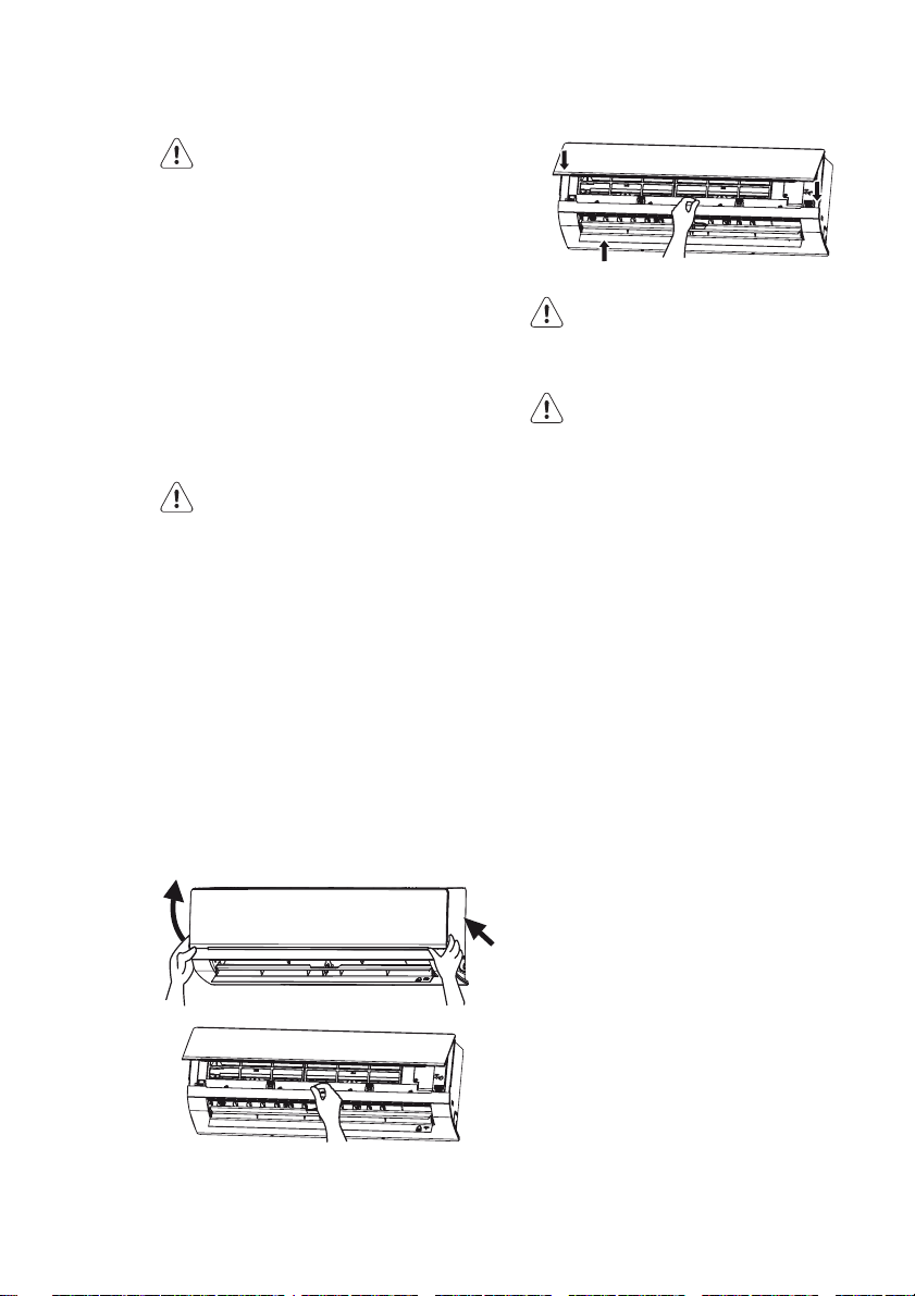
Cleaning the front panel
1. Remove the front panel.
2. Clean the front panel using a cloth
slightly moistened with water.
3. Install the front panel.
Cleaning the air filter
The air filter must be cleaned every
3 months.
WARNING
r© $O©NOT©TOUCH©THE©kN©OF©THE©INDOOR©UNIT©
to prevent personal injury.
CAUTION
r© $O©NOT©USE©WATER©ABOVE©©§#©
to clean the air filter to prevent
deformation or discoloration.
1. Open the front panel.
2. Remove the air filter.
3. Remove dust from the air filter using
a vacuum cleaner.
4. If the air filter is dirty, clean the air
filter with warm water and a mild
detergent. Allow the air filter to dry
naturally in a cool, dark place.
5. Install the air filter.
6. Close the front panel.
Check before use
r© -AKE©SURE©THAT©NOTHING©OBSTRUCTS©THE©
air inlet or the air outlet.
r© -AKE©SURE©THAT©THE©INSTALLATION©STAND©
of the outdoor unit is not damaged.
If the installation stand is damaged,
consult a qualified technician.
r© -AKE©SURE©THAT©THE©BATTERIES©ARE©
inserted into the remote control.
Maintenance after use
r© $ISCONNECT©THE©UNIT©FROM©THE©POWER©
supply.
r© #LEAN©THE©kLTERS©AND©THE©HOUSINGS©OF©
the indoor unit and the outdoor unit.
r© 2EMOVE©ANY©OBSTRUCTIONS©FROM©THE©
outdoor unit.
TROUBLESHOOTING
ENGLISH 13
CAUTION
r©4HE©UNIT©IS©NOT©USERSERVICEABLE©$O©
not attempt to repair the unit yourself
to prevent electric shock or fire. Have
Problem Solution
The unit does not operate. The unit does not operate if it is switched on
immediately after switching off the unit. After
switching off the unit, wait for approximately 3
minutes before switching on the unit.
Odours are emitted. Some odours may be emitted from the indoor
unit as the result of room smells (furniture,
tobacco, etc.) which have been taken into
the unit. If the odours persist, contact an
authorised service centre.
Water-kowing noise. The water-kowing noise is the refrigerant
kowing inside the unit.
Mist is emitted in COOL mode. During cooling operation, mist may be
emitted from the indoor unit due to high
room temperature and humidity. The mist will
disappear if the room temperature and humidity
decrease.
Cracking noise. The cracking noise is the sound of friction
caused by expansion and/or contraction of the
front panel or other parts due to the change in
temperature.
The unit cannot be started. Is the unit disconnected from the power
supply?
Is the mains plug loose?
Is the circuit protection device tripped off?
Is the voltage higher or lower? (tested by
professionals)
Is the timer function used correctly?
The cooling/heating effect is poor. Is the temperature set correctly?
Is the air inlet or the air outlet blocked?
Is the air jlter dirty?
Is the window or the door open?
Is a low fan speed set?
Are there heat sources in the room?
the unit repaired by an authorised
service centre. The following checks
can save you time and money before
consulting an authorised service
centre.
14 www.electrolux.com
The remote control does not
work.
Is there any magnetic or electrical interference
near the unit? If yes, remove and reinsert the
batteries.
Is the remote control within its transmitting and
receiving range without any obstructions? If
necessary, replace the batteries.
Is the remote control damaged?
Water leakage in indoor unit. The room humidity is high.
Condensing water overkows.
The drain hose is loose.
Water leakage in outdoor unit. In COOL mode, water condensate is generated
around the pipes and connection joints.
In HEAT mode, the water on the heat
exchanger drips out.
In defrost mode, the thaw water kows out.
Noise from indoor unit. The noise emitted when the fan or compressor
relay is switched on or off.
If the defrost mode is started or stopped, you
will hear the sound of refrigerant kowing in the
reverse direction.
The indoor unit cannot blow air. In HEAT mode, when the temperature of the
indoor heat exchanger is low, the airkow is
stopped within 2 minutes in order to prevent
cold air.
In HEAT mode, when the outdoor temperature
is low or the outdoor humidity is high, frost will
be formed on the outdoor heat exchanger. The
unit will defrost automatically and the indoor
unit will stop blowing air for 3-12 minutes.
In DRY mode, the indoor fan will stop
blowing air for 3-12 minutes in order to avoid
condensing water being vapourised again.
In defrost mode, water or vapour may be
emitted.
Moisture on air outlet. If the unit operates at high humidity for a long
time, moisture will be generated on the grill of
the air outlet.
There is harsh sound during
operation.
Immediately stop operation, disconnect the
unit from the power supply and contact an
authorised service centre.
Strong odours are emitted during
operation.
Immediately stop operation, disconnect the
unit from the power supply and contact an
authorised service centre.
ENGLISH 15
Water is leaking from the indoor
unit.
The air switch or protection
switch often interrupts power
supply.
Water or other liquid is splashed
into the unit.
Mains cord and mains plug are
overheated.
Error code Solution
C5: Malfunction of connector
jumper.
F1: Malfunction of indoor ambient
temperature sensor.
F2: Malfunction of evaporator
temperature sensor.
H1: Defrosting
E3: Low pressure
warning
Immediately stop operation, disconnect the
unit from the power supply and contact an
authorised service centre.
Immediately stop operation, disconnect the
unit from the power supply and contact an
authorised service centre.
Immediately stop operation, disconnect the
unit from the power supply and contact an
authorised service centre.
Immediately stop operation, disconnect the
unit from the power supply and contact an
authorised service centre.
Check if the connector jumper contacts
properly. If necessary, replace the old circuit
board with a new circuit board.
Check if the indoor room temperature sensor is
connected properly.
Check if the evaporator temperature sensor is
connected properly.
It is normal. The unit is in defrosting mode
and heating will recommence after 1-10min.
Your air conditioner has lost refrigerant.
Contact your installer to check for
potential leaks.
OPERATION TIPS
Cooling operation
Air conditioners absorb heat from indoor
and transmit the heat to the outdoor
unit in order to decrease the room
temperature. The cooling capacity will
increase or decrease according to the
outdoor temperature.
Anti-freezing function
If the unit is in COOL mode and in a
low ambient temperature, frost will be
formed on the heat exchanger of the
indoor unit. If the temperature of the
heat exchanger decreases below zero,
the compressor will stop operation to
protect the unit.
Heating operation
Air conditioners absorb heat from
outdoor and transmit the heat to the
indoor unit in order to increase the room
temperature. The heating capacity will
increase or decrease according to the
outdoor temperature.
Defrosting
the outdoor humidity is high, frost
will form on the outdoor unit during
extended operation. The heating
capacity will decrease. The unit may
stop operation during defrosting.
the indoor unit and outdoor unit will
stop operation.
flashes and the outdoor unit may emit
vapour. This is normal operation to
remove frost from the heat exchanger
of the outdoor unit.
will resume automatically.
16 www.electrolux.com
Anti-cold air function
In HEAT mode, the indoor fan will not
operate in order to prevent cold air from
blowing out if the indoor heat exchanger
does not reach a certain temperature in
one of the following situations:
when the heating operation starts;
when the defrosting operation is
when heating at low temperature.
Gentle breeze
The indoor unit may blow gentle breeze
and the horizontal louvre rotates to a
Indoor side (°C) Outdoor side (°C)
Tip for energy saving
Do not overcool or overheat. Setting
the temperature at a moderate level
helps energy saving.
Cover windows with a blind or a
curtain. Blocking sunlight and air from
outdoor is favorable for cooling.
certain position in one of the following
situations:
In HEAT mode, the compressor does
not start operation after switching on
the unit.
In HEAT mode, the temperature
reaches the set value and the
compressor has stopped operation
for 1 minute.
Operating temperature range
The operating temperature range for
cooling mode is -15-(+48˚C). The
operating temperature range for heating
mode is -20-(+24)˚C.
8423gnilooc .xaM
51-12gnilooc .niM
4272gnitaeh .xaM
02-02gnitaeh .niM
Clean air
Clogged air filters lead to inefficient
operation and energy waste.
every two weeks.
Tip for relative humidity
If the unit is operated in an area with
a relative humidity of more than 80%
for a long time, condensate may drip
from the indoor unit.
INSTALLATION
Installation notes
Not following the instructions can
cause personal injury and/or property
damage.
Not following the instructions can
cause the unit to fail.
Let the unit be installed by an
authorised service centre.
Let the unit be installed in compliance
with local and governmental
regulations.
Let the unit be installed according to
the instructions from this manual.
First contact an authorised service
centre before relocating an already
installed unit
Disconnect power before working on
the unit.
Let the mains cable be repaired by an
authorised service centre or qualified
technician for units with Y-attachment.
The mains plug must remain
accessible after installation.
Keep
the interconnection cable and the
distance between
ENGLISH 17
refrigerant circuit because the circuit
operating temperature is high.
outdoor unit are not included in the
unit.
indoor unit.
Installation site
- high frequency electromagnetic
equipment (e.g. welding equipment or
- high salinity (e.g. close to coastal
- poor air quality.
Indoor unit
distances specified in this document.
Do not block the air inlet or the air
outlet.
extremely high humidity.
children.
Outdoor unit
distances specified in this document.
outlet.
children.
sufficient ventilation.
produced noise and airflow will not
disturb neighbors or animals.
exposed to direct sunlight or strong
wind.
the weight and vibration of the unit.
indoor unit and the outdoor unit must
be less than 5 m.
must be less than 10 m.
and maintenance.
indoor unit.
Safety precautions for electrical
appliances
support the weight and vibration of
the unit.
and maintenance.
between the unit and other electrical
appliances.
the condensate water can be easily
drained.
direct sunlight.
(RCD) to protect against personal
injury in case of leakage currents.
with a contact separation of at least
3 mm in all poles in fixed wiring. For
models with a mains plug, make sure
that the mains plug is within reach
after installation.
local electrical safety regulations and
with other relevant local regulations
accordance with national wiring
regulations.

18 www.electrolux.com
r© $O©NOT©SUBJECT©THE©MAINS©CABLE©TO©
force.
r© 4HE©DISTANCE©BETWEEN©THE©UNIT©AND©
heat sources is at least 1.5 m.
and heat tripping to prevent short
circuit and overload. The suitable
capacity is specified in the following
table.
r© 5SE©AN©AIR©SWITCH©4HE©AIR©SWITCH©MUST©
have functions for magnetic tripping
Air conditioner (Btu) Air switch capacity
09-12K 16A
NOTE
r© -AKE©SURE©THAT©THE©LIVE©WIRE©THE©
neutral wire and the ground wire
in the mains socket are properly
connected.
r© )NADEQUATE©OR©INCORRECT©ELECTRICAL©
connections can cause electric shock
or fire.
r© 4HE©YELLOWGREEN©WIRE©IS©THE©GROUND©
wire that cannot be used for other
purposes. Improper grounding can
cause electric shock.
r© 4HE©GROUND©RESISTANCE©MUST©COMPLY©
with local regulations.
r© 4HE©MAINS©SUPPLY©MUST©HAVE©RELIABLE©
ground terminal. Do not connect
the ground wire to water pipes, gas
Grounding requirements
r© 4HE©UNIT©IS©A©TYPE©)©ELECTRICAL©
appliance. Make sure that the unit is
properly grounded.
pipes, contamination pipes or other
possible unsafe places.
r© &USES©MUST©COMPLY©WITH©THE©
prescribed model and rating printed
on the fuse cover or circuit board.
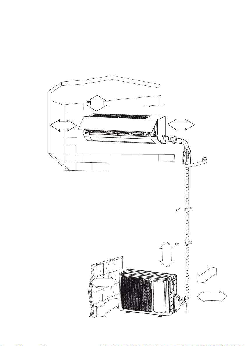
Installation drawing
The dimensions required for proper
installation of the unit include the
minimum permissible distances to
adjacent parts.
min.
5cm*
ENGLISH 19
15cm
30cm
15cm
50
cm
30cm
200cm
* Recommended distance for maximum airflow is 15 cm.
NOTE: We suggest to install the indoor unit at height above of 230cm.
50cm
20 www.electrolux.com
Indoor unit
Installing the mounting plate
1. Install the mounting plate
horizontally.
2. Fix the mounting plate to the wall
with screws. Make sure that the
mounting plate is fixed firmly enough
to support approximately 60 kg. The
weight must be evenly shared by
each screw.
Drill piping hole
1. Slant the piping hole (Ø 55 mm) on
the wall slightly downward to the
outdoor side.
2. Insert the piping-hole sleeve into
the hole to prevent damage to the
connection piping and wiring.
Installing the drain hose
1. Connect the drain hose to the outlet
pipe of the indoor unit. Bind the joint
with rubber belt.
2. Put the drain hose into the insulating
tube.
3. Wrap the insulating tube with wide
rubber belt to prevent the insulating
tube from shifting. Slant the drain
hose slightly downward for smooth
drainage of the condensate water.
NOTE
r© 4HE©INSULATING©TUBE©MUST©BE©
connected reliably with the sleeve
outside the outlet pipe. The
drain must be slanted downward
slightly without distortion, bulge or
fluctuation. Do not put the outlet of
the drain hose in water to prevent the
drain hose from freezing.
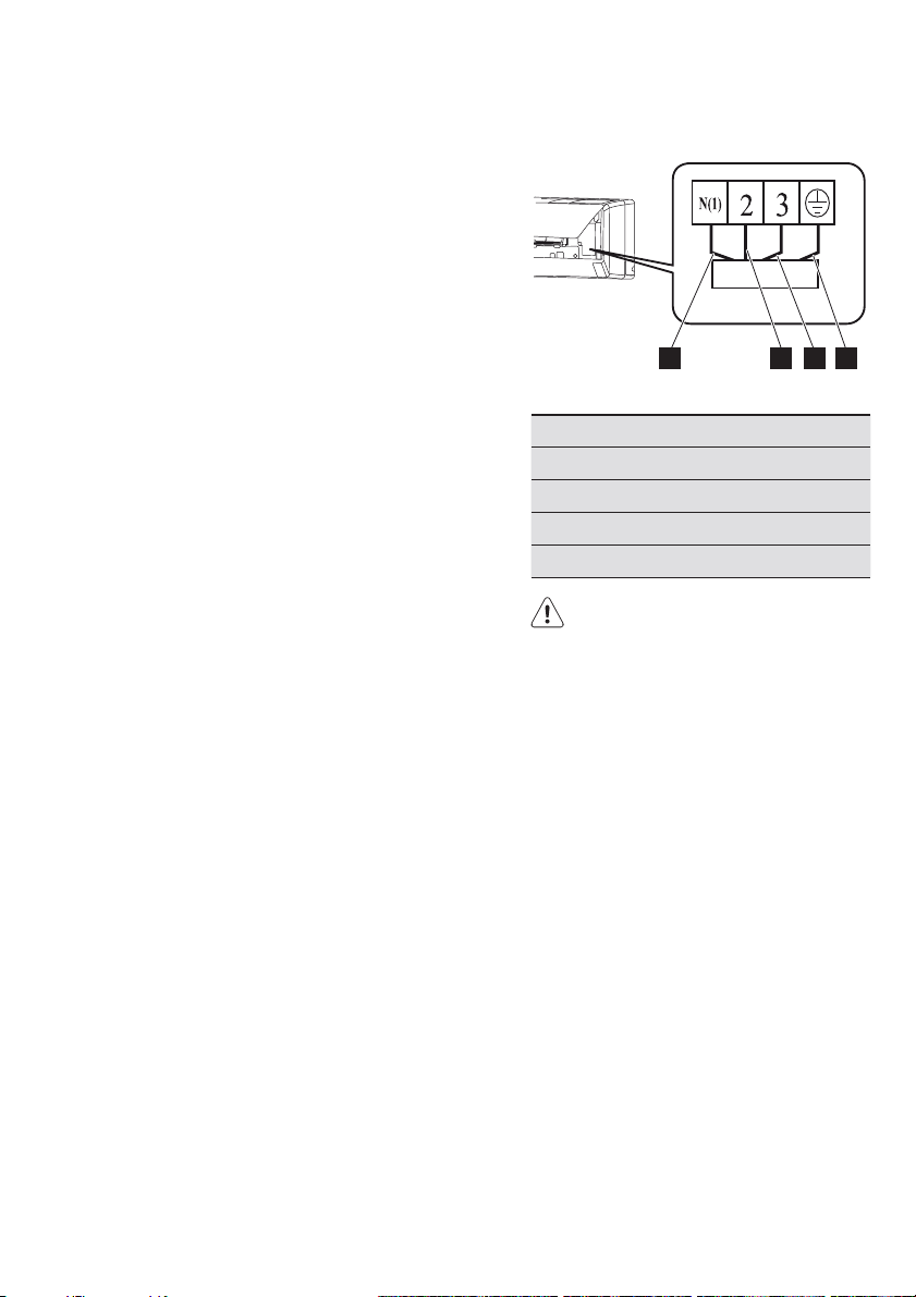
Electrical wiring indoor unit:
1 2 3 4
Nr. Colour
1 Blue (neutral)
2 Black
3 Brown
4 Yellow (ground)
CAUTION
r© #HECK©THE©WIRING©TO©MAKE©SURE©THAT©
there is no short circuit. Incorrect
wiring can cause malfunction.
1. Open the front panel.
2. Remove the wiring cover.
3. Fix the mains cord to the terminal
board (as shown).
4. Guide the mains cord through the
hole at the back of the indoor unit.
5. Install the cord anchorage and
wiring cover.
6. Close the front panel.
NOTE
r© 4HE©ELECTRICAL©WIRING©BETWEEN©THE©
indoor unit and the outdoor unit
must be connected by a qualified
electrician.
r© 4IGHTEN©THE©TERMINAL©SCREWS©TIGHTLY
r© !FTER©TIGHTENING©THE©SCREWS©PULL©THE©
wire slightly to confirm whether it’s
firm or not.
r© -AKE©SURE©THAT©THE©ELECTRICAL©
connections are properly grounded to
prevent electric shock.
ENGLISH 21
t Make sure that the wiring connections
are secure and that the cover plates
are properly mounted to prevent
electric shock.
Installing the indoor unit
The piping can be output from the right,
the right rear, the left or the left rear.
1. When routing the piping and wiring
from the left or right of indoor unit,
cut off the tailings from the chassis
when necessary.
2. Remove the piping from the body
case.
3. Wrap the piping, the mains cords
and the drain hose with the tape.
4. Guide the piping, the mains cords
and the drain hose through the
piping hole.
5. Firmly hang the mounting slots of
the indoor unit on the upper hooks
of the mounting plate.
6. The installation site must be at least
230 cm above the floor surface.
Installing the connection pipe
1. Align the center of the piping flare
with the related valve.
2. Screw in the flare nut by hand and
then tighten the nut with spanner
and torque wrench. Refer to the
following table.
outdoor unit. Handle the piping
bending with care. Do not damage
the connection pipe. Firmly tighten
the joint nut to prevent leakage.
t The pipes connecting the indoor and
outdoor unit are not included in the
unit.
t In case the connective pipe length is
longer than 7.5m charge the unit with
additional refrigerant. Add 20g/m of
R410A for models with a capacity of
less than 6500W. Add 50g/m for the
other models.
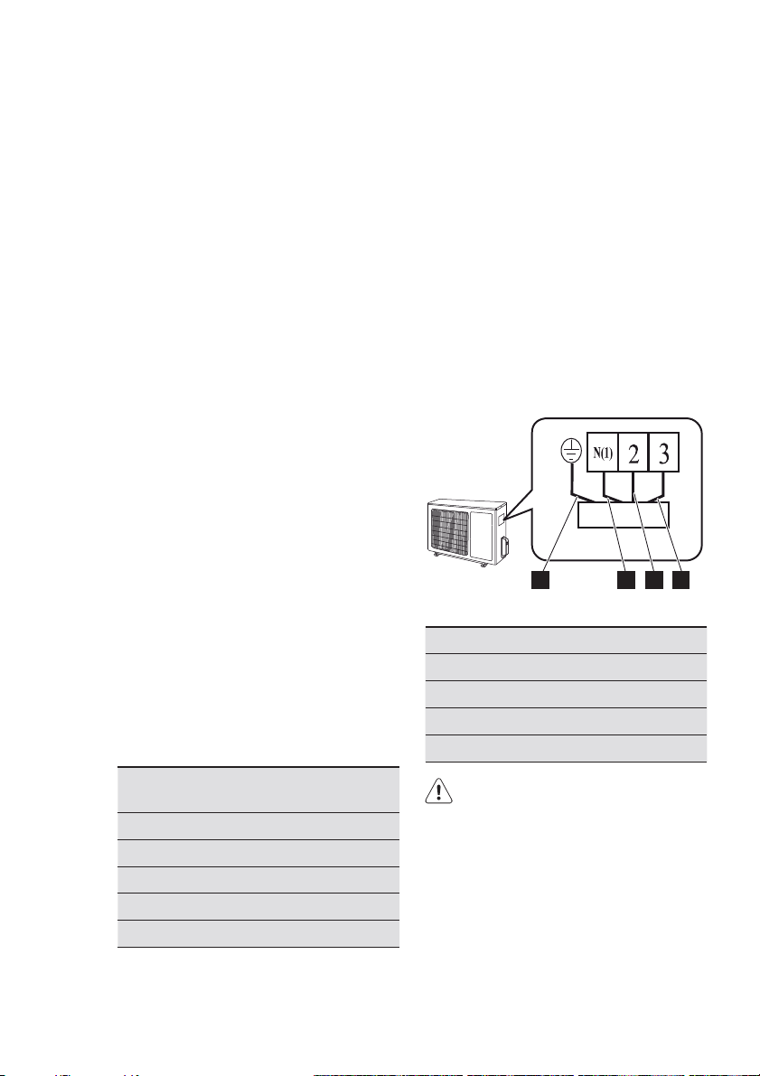
Outdoor unit
Electrical wiring
1 2 3 4
Nr. Colour
1
2
3
4
Yellow (ground)
Blue (neutral)
Black
Brown
Hex nut
diameter (mm)
Tightening
torque (Nm)
Ø 6 15-20
Ø 9.52 30-40
Ø 12 45-55
Ø 16 60-65
Ø 19 70-75
NOTE
t First connect the connection pipe
to the indoor unit and then to the
CAUTION
t Check the wiring to make sure that
there is no short circuit. Incorrect
wiring can cause malfunction.
1. Remove the handle (x2) on the right
side plate of outdoor unit.
2. Remove mains cord anchorage.
3. Connect the mains cord to the
terminal board.
4. Lock the position of the cord with
wire clamps.
5. Check for improper connections.
22 www.electrolux.com
6. Reinstall the handle.
NOTE
r© #HECK©FOR©FREE©SPACE©BETWEEN©THE©
connection and the lock positions.
CAUTION
r© /PEN©THE©STEM©OF©THE©PACKED©VALVE©
until it hits against the stopper. Do not
try to open it further. Close the stem
of the packed valve with a special
tool. Close the cap of the packed
valve with a spanner.
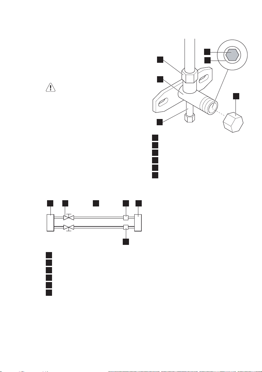
NOTE
The outdoor unit has two outlets, the
low side outlet and the high side outlet.
Only the low side outlet contains a
charging port. The low side outlet is
shown below.
2 5 4 1
2
5
5
1
1
3
1
Valve body
2
Valve stem
3
Charge port
4
Stopper
5
Flare nut
6
Cap
12 35 4
4
6
6
1
Indoor unit
2
Outdoor unit
3
Refrigerant
4
Gas
5
Packed valve
6
Half union
6
ENGLISH 23
1
2
48
3
5
7
1
Valve body
2
Valve stem
3
Charge port
4
Stopper
5
Flare nut
6
Cap
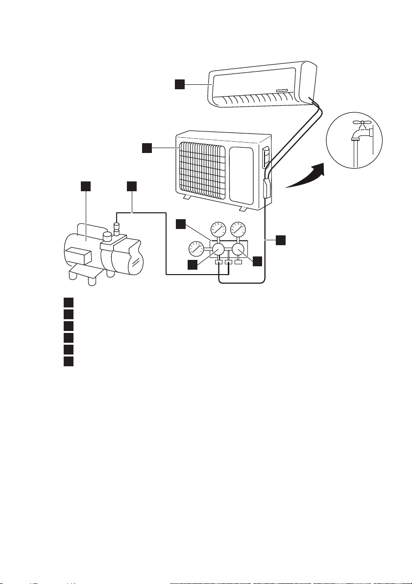
Using the vacuum pump
1. Fully tighten the flare nuts at
connection point A, B, C and D.
2. Connect vacuum hose between
charging port and the manifold.
3. Connect the other charge hose
between manifold and the vacuum
pump.
4. Fully open the handle Lo of the
manifold valve.
5. Operate the vacuum pump to
evacuate.
6. Slightly loosen the flare nut of the Lo
valve on the gas pipe side.
7. Check if air is entering (noise of
the vacuum pump changes and
6
compound meter indicates 0 instead
of minus).
8. Tighten the flare nut.
9. Make evacuation for 15 minutes or
more and check that the compound
meter indicates -7.6 x 10
5
(-1x10
Pa) (-0,7Bar).
5
μmHg
10. Fully close the handle Lo of the
manifold valve and stop the
operation of the vacuum pump.
11. Turn the stem of the packed valve B
about 45° counterclockwise for
6~7 seconds after the gas comes
out, then tighten the flare nut again.
12. Make sure the pressure display
in the pressure indicator is a
little higher than the atmosphere
pressure. This to verify if the
refrigerant does flow correctly
through the tubes.
13. Remove the vacuum hose.
14. Replace the charging port cap.
15. Fully open the packed valve stems B
and A.
24 www.electrolux.com
16. Securely tighten the cap of the
packed valves.
Outdoor condensate drainage (heatpump unit only)
During heating operation, condensate
water and defrosting water must be
drained through the drain hose.
1. Install the outdoor drain connector in
a Ø 25 mm hole on the base plate.
2. Attach the drain hose to the
connector so that water in the
outdoor unit can be drained. The
hole diameter 25 must be plugged.
Check after installation
Items to be checked Possible malfunction
Has the unit been jxed jrmly? The unit may drop, shake or emit noise.
Have you done the refrigerant leakage
test?
Is the thermal insulation sufjcient? Condensation.
Is the water drainage satisfactory? Water leakage.
Is the voltage in accordance with the
rated voltage on the nameplate?
Is the electrical wiring or piping
connection installed correctly and
securely?
Has the unit been securely grounded? Electrical leakage.
Is the mains cable as specijed? Electrical malfunction or damage to
Is the air inlet or the air outlet blocked? Insufjcient cooling or heating.
Is the length of the connection pipes
and the refrigerant capacity as specijed
Is the length of the connection pipes
and the refrigerant capacity as specijed
Insufjcient cooling or heating.
Electrical malfunction or damage to the
unit.
Electrical malfunction or damage to the
parts.
parts.
Inaccurate refrigerant capacity.
Inaccurate refrigerant capacity.
Operation test
Before operation test
r© $O©NOT©CONNECT©THE©UNIT©TO©THE©POWER©
supply before the installation is
completed.
r© 4HE©ELECTRICAL©WIRING©MUST©BE©
connected correctly and securely.
r© 4HE©CUTOFF©VALVES©OF©THE©CONNECTION©
pipes must be opened. Refer to the
section “Vacuuming and leakage
test”.
r© 4HE©UNIT©MUST©BE©CLEANED©THOROUGHLY
Operation test method
1. Connect the unit to the power
supply.
2. Press the ON/OFF button to switch
on the unit.
3. Press the MODE button to set the
operation mode and check whether
the operation is as expected.
HEALTH FILTER
ENGLISH 25
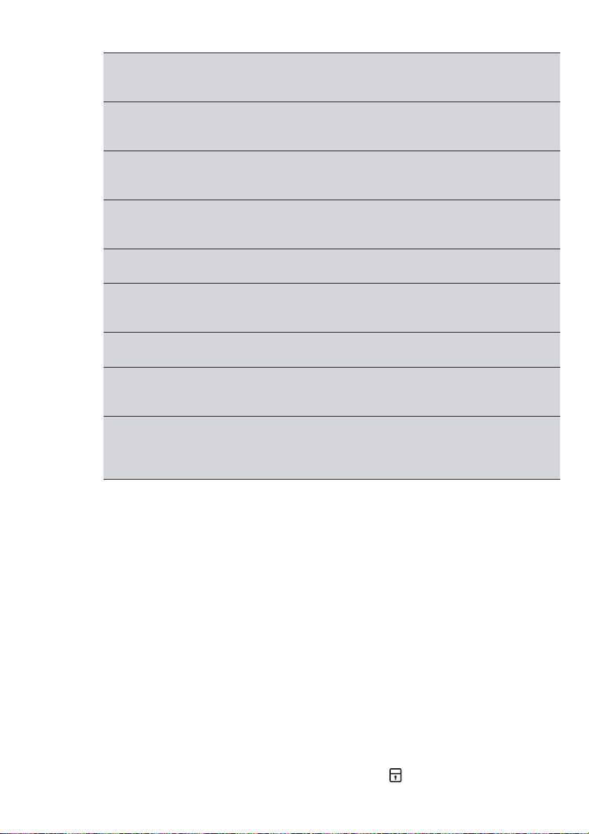
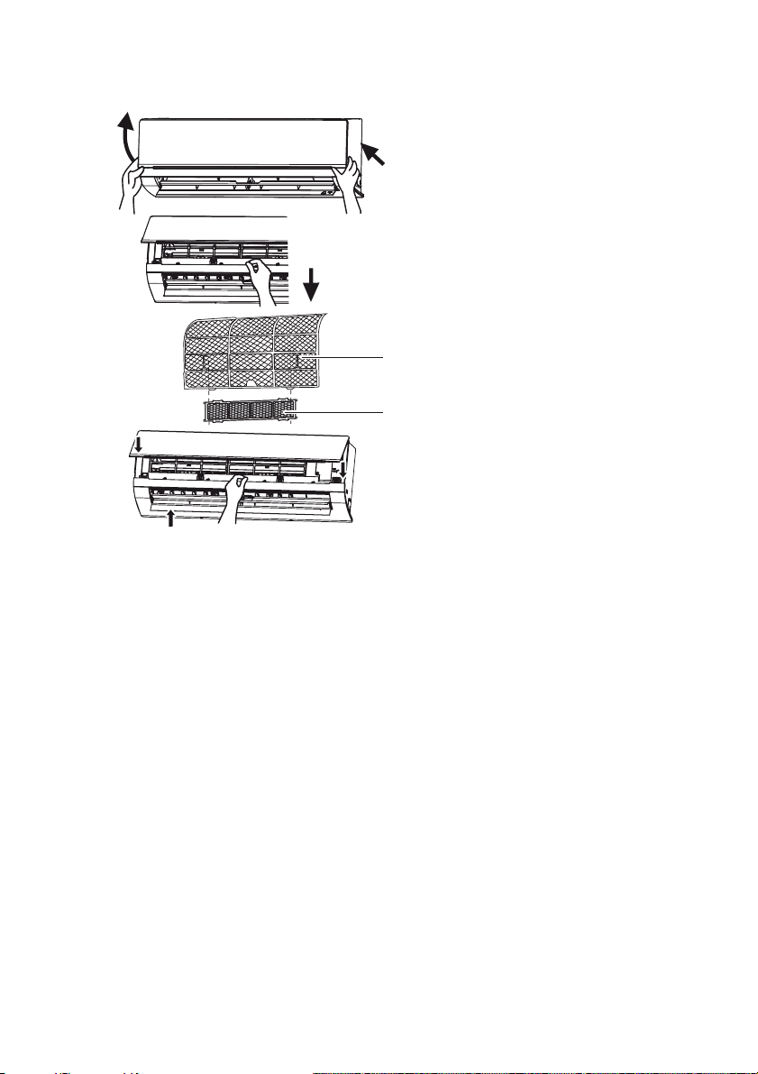
Installation
1. Open the front panel.
2. Remove the air filter (A).
3. Attach the health filter (B) to the air
filter (A).
4. Install the air filter (A).
5. Close the front panel.
Cleaning and maintenance
1. Remove the health filter.
2. Remove dust from the health filter
A
B
using a vacuum cleaner.
3. If the health filter is dirty, clean the
health filter with warm water and a
mild detergent. Allow the health filter
to dry naturally in a cool, dark place.
4. Install the health filter.
Service interval
The service interval for the health filter
is approximately one year under normal
condition. The health filter must be
replaced when the surface becomes
black (green).
26 www.electrolux.com
INDHOLD
Sikkerhedsforanstaltninger ...................................................................................... 27
forløb ...................................................................................................................... 28
Fjernbetjening ......................................................................................................... 28
Vedligeholdelse og rengøring................................................................................... 34
Fejlsøgning.............................................................................................................. 35
Tips til betjening ...................................................................................................... 37
Installation............................................................................................................... 38
Sundhedsfilter......................................................................................................... 47
VI TÆNKER PÅ DIG
Tak for dit køb af et Electrolux-apparat. Du har valgt et produkt, som giver dig årtiers
professionel erfaring og innovation på én gang. Genialt og elegant. Det er designet med dig
i tankerne. Så uanset hvornår du bruger det, kan du være sikker på, at du får fantastiske
resultater hver gang.
Velkommen til Electrolux.
Besøg vores websted for:
Få rådgivning, brochurer, fejlfinding, serviceinformation:
www.electrolux.dk
Registrere dit produkt for bedre service:
www.electrolux.com/productregistration
Købe tilbehør, forbrugsvarer og originale reservedele til dit apparat:
www.electrolux.com/shop
KUNDEPLEJE OG SERVICE
Vi anbefaler brugen af originale reservedele.
Sørg for at have følgende data tilgængelig, når du kontakter service.
Du finder oplysningerne på maskinens typeskilt. Model, PNC, Serienummer.
Advarsel /Forsigtig-Sikkerhedsanvisninger.
Generelle oplysninger og gode råd
Miljøoplysninger
Ret til ændringer uden varsel forbeholdes.
SIKKERHEDSFORANSTALTNINGER
2KSNAD 7
drift.
op i den.
bruges af personer (herunder børn)
med nedsat fysisk, sensorisk eller
psykisk funktionsevne, eller som
mangler den nødvendige erfaring
eller viden, med mindre den, der har
ansvaret for deres sikkerhed, først har
instrueret dem eller har kontrolleret, at
de kan betjene det korrekt.
sikre, at de befinder sig på afstand af
apparatet.
ubehagelige brændte lugte), skal du
afbryde enheden fra strømforsyningen
og kontakte et autoriseret
servicecenter. Hvis anormaliteten
forbliver, kan klimaanlægget blive
beskadiget eller endda forårsage
elektrisk stød eller brand.
skal du slukke for enheden og koble
enheden fra strømforsyningen. Hvis
enheden er sluttet til en sikringstavle,
skal du fjerne tavlen.
eller kompressoren. Elektriske
komponenter kan ikke betjenes.
for at forhindre elektrisk stød.
for at forhindre elektrisk stød eller
brand. Få enheden repareret af et
autoriseret servicecenter.
1 meter fra enheden for at forhindre
brand eller eksplosion.
forhindre personskade.
at anbringe tung ting på udeenheden.
luftudgangen.
for at forhindre elektrisk stød.
hænder for at forhindre elektrisk stød.
genstande ind i luftindgangen eller
luftudgangen.
direkte for luftstrømmen.
kølig luft i længere tid.
eller signalkontrolledningen.
Hvis netledningen eller
signalkontrolledningen er beskadiget,
skal den udskiftes af en kvalificeret
elektriker.
for at forhindre elektrisk stød eller
brand.
overensstemmelse med nationale
bestemmelser for el-sikkerhed.
Forkert el-installation kan føre til
overophedning og brand i kablet,
stikket eller stikkontakten.
Undlad at tænde og slukke for
enheden jævnligt.
beskadiges elektriske elementer
nemt. Hvis spændingen er for
lav, ryster kompressoren kraftigt
og beskadiger kølesystemet
formål, som f.eks. konservering af
fødevarer eller tørring af tøj.
at spare el-energi.
i længere tid under drift.
skal du bruge fjernbetjeningen til at
justere den vandrette og lodrette
retning af luftstrømmen.
usorteret kommunalaffald. Det er
nødvendigt at indsamle dette affald
separat til specialbehandling.
Undlad at bruge ild eller hårtørrer til at
tørre filteret til avoideformation eller
brandfare.
Hold varmen fornuftigt material in least
1 meter far from luftstrøm ved avoid
på beskadige.
28 www.electrolux.com
BESKRIVELSE
1
9
10 11 3
1
2
7
13
12
8
4
5
14
Indeenhed
2
Luftindgang (indeenhed)
3
Luftudgang (indeenhed)
4
Udeenhed
5
Luftindgang (udeenhed)
6
Luftudgang (udeenhed)
7
Netledning
8
Fjernbetjening
9
Frontpanel
10
Filter
11
Vandret lamel
12
Vægrør
13
Tape
14
Tilslutningsrør
15
Afløbsslange
16
Afløbstilslutning
15
16
6
16
FJERNBETJENING
Fjernbetjeningen kan bruges til
forskellige modeller. Afhængigt
af modellen er visse funktioner
på fjernbetjeningen muligvis ikke
tilgængelige.
FORSIGTIG
r© 5NDLAD©AT©TABE©ELLER©KASTE©
fjernbetjeningen.
r© 5NDLAD©AT©HLDE©VSKE©Pė©
fjernbetjeningen.
r© 5NDLAD©AT©UDSTTE©FJERNBETJENINGEN©
for direkte sollys.
r© 5NDLAD©AT©ANBRINGE©FJERNBETJENINGEN©
på områder, hvor det er meget varmt.
BEMÆRK
r© 3RG©FOR©AT©DER©IKKE©ER©GENSTANDE©
mellem signalsenderen på
fjernbetjeningen og enhedens
signalmodtager.
18
24
29
32
30
25
31
22
23
20
17
Fan
Mode
Swing-
Slee
Turbo
V
p
ION
Swing-H
Quiet
Filter
Timer
X-Fan
I Feel
On
Timer
Clock
Light
Off
19
21
33
26
27
28

Forklaring på knapper
Nr. Knap Forklaring
17 TÆND/SLUK Slå displayet til ved at trykke på en vilkårlig knap. Tryk på knappen
18 MODE
(TILSTAND)
19 FAN
(BLÆSER)
20
UP (OP)
21 DOWN
(NED)
v
22 CLOCK (UR) Tryk på knappen for at indstille timeren. Hvis ursymbolet blinker,
23 LIGHT (LYS) Tryk på knappen for at slå indeenhedens display til eller fra.
igen for at slukke for enheden.
Tryk på knappen for at indstille driftstilstanden: AUTO, COOL
(Afkøling), DRY (Tørring), FAN (Blæser) og HEAT (Varme).
Standardindstilling: AUTO.
AUTO
AUTO COOL DRY FAN HEAT
I tilstanden AUTO vises temperaturen ikke. I tilstanden HEAT (Varme)
er startværdien 28 °C (82 °F). I andre tilstande er startværdien 25 °C
(77 °F).
Tryk på -knappen for at vælge blæserhastighed AUTO, LOW (Lav),
MEDIUM LOW (Middellav), MEDIUM (Middel), MEDIUM HIGH
(Middelhøj) og HIGH (Høj). Standardindstilling: AUTO. I tilstanden DRY
ørring) kan kun LOW (Lav) indstilles.
(T
AUTO
Auto Low Medium-low Medium Medium-high High
Tryk på knappen for at øge temperaturen. Hold knappen trykket ind
^
i to sekunder for at øge processens hastighed. Slip knappen for at
indstille temperaturen og sende ordre om, at °C/°F-signalet vil blive
vist konstant.
Temperaturområde: 16-30 °C (61-86 °F).
I tilstanden AUTO kan temperaturen ikke indstilles. Hvis du trykker på
knappen UP (Op) eller DOWN (Ned), udsendes der et bip.
Tryk på knappen for at sænke temperaturen. Hold knappen trykket
ind i to sekunder for at øge processens hastighed. Slip knappen for
at indstille temperaturen og sende ordre om, at °C/°F-signalet vil blive
vist konstant.
Temperaturområde: 16-30 °C (61-86 °F).
I tilstanden AUTO kan temperaturen ikke indstilles, men der kan
afsendes ordre ved at trykke på knappen.
skal du trykke på knappen UP (Op) eller DOWN (Ned) for at indstille
tiden. Hold knappen trykket ind i to sekunder for at øge processens
hastighed. Tryk igen på knappen CLOCK (Ur) for at indstille uret.
Ursymbolet holder op med at blinke.
Efter udskiftning af batteriet vises “12:00 PM”. Hvis ursymbolet er
synligt, vil den reelle tid blive vist. Hvis ursymbolet ikke er synligt, vil
timeren blive vist.
Hvornår tændes, vil lyset symbol blive vist.
Standardindstilling: OFF (Fra).
” ”
” ”
2KSNAD 9
30 www.electrolux.com
24 TURBO I tilstanden COOL (Afkøling) eller HEAT (Varme) skal du trykke
på knappen for at aktivere eller deaktivere turbofunktionen.
Hvis turbofunktionen er aktiveret, vil turbosymbolet blive vist.
TURBO
” ”
Standardindstilling: OFF (Fra).
Hvis turbofunktionen er aktiveret, vil enheden fungere ved
turbohastighed for at afkøle eller opvarme hurtigt, så den omgivende
temperatur nærmer sig den indstillede temperatur hurtigst muligt.
Hvis betjeningstilstanden eller blæserhastigheden ændres,
vil turbosymbolet ikke blive vist.
25 X-FAN
(X-BLÆSER)
I tilstanden COOL (Afkøling) eller DRY (Tørring) skal du trykke på
knappen for at aktivere eller deaktivere funktionen X-FAN (X-blæser).
Hvis funktionen X-FAN (X-blæser) er aktiveret, vil symbolet for X-FAN
(X-blæser) blive vist. Standardindstilling: OFF (Fra).
” ”
Hvis funktionen X-FAN (X-blæser) er aktiveret, vil indeblæseren
fortsætte driften ved lav hastighed i 2 minutter, efter enheden er
blevet slukket. Denne funktion forhindrer en e
ventuel kondensering på
indeenhedens kølige dele. Tryk på knappen X-FAN (X-blæser) for at
slukke for enheden under processen.
Hvis funktionen X-FAN (X-blæser) er deaktiveret, vil enheden blive
slukket med det samme.
I tilstanden AUTO, FAN (Blæser) eller HEAT (Varme) er X-FAN
(X-blæser) ikke tilgængelig.
26 ION-FILTER Tryk på knappen for at aktivere eller deaktivere driften
afsundhedsfilteret. Hvis funktionen ION-FILTER er aktiveret,
27 TIMER ON
(TIMER TIL)
vil symbolet for ION-FILTER blive vist.
Tryk på knappen for at indstille timerfunktionen for at slå enheden
til. Hvis symbolet for TIMER ON (Timer til) blinker, skal du trykke
”ON”
” ”
på knappen UP (Op) eller DOWN (Ned) for at indstille tiden. Hold
knappen trykket ind i to sekunder for at øge processens hastighed.
Tryk på knappen for at indstille timeren. Standardindstilling: 5:00 AM
(12-timers tilstand). Tryk igen på knappen for at annullere timerfunktionen.
28 TIMER OFF
(TIMER FRA)
Tryk på knappen for at indstille timerfunktionen for at slå enheden
fra. Hvis symbolet for TIMER OFF (Timer fra) blinker, skal du
”OFF”
trykke på knappen UP (Op) eller DOWN (Ned) for at indstille tiden.
Hold knappen trykket ind i to sekunder for at øge processens hastighed.
Tryk på knappen for at indstille timeren. Standardindstilling: 5:00 AM
(12-timers tilstand). Tryk igen på knappen for at annullere timerfunktionen.
29 SWING-V
(SVING-V)
30 SWING-H
(SVING-H)
Tryk på knappen for at aktive
re eller deaktivere den lodrette
svingfunktion. Hvis funktionen SWING-V (SVING-V) er aktiveret,
vil symbolet for SWING-V (SVING-V) blive vist.
” ”
Tryk på knappen for at aktivere eller deaktivere den vandrette
svingfunktion. Hvis funktionen SWING-H (SVING-H) er aktiveret,
vil symbolet for SWING-H (SVING-H) blive vist.
” ”
31 I FEEL (JEG
FØLER)
Tryk på knappen for at aktivere eller deaktivere funktionen I FEEL (Jeg
føler). Hvis funktionen I FEEL (Jeg føler) er aktiveret, vil I symbolet
” ”
for I FEEL (Jeg føler) blive vist.
Hvis symbolet for I FEEL (Jeg føler) er aktiveret, vil fjernbetjeningen
sende den omgivende temperatur til hovedenheden hver gang, der er
gået 10 minutter, eller når du trykker på en af knapperne.
 Loading...