

Electrolux EWX11831, EWX14931 Service Manual
SERVICE MANUAL
Washing machines
with electronic control
system
EWX11831
EWX14931
UIMC / EMC14
Inverter
Technical and functional
characteristics
NEW
COLLECTION
SERIES
7/8/9
ELECTROLUX HOME PRODUCTS
Customer Care - EMEA
Training and Operations Support
Technical Support
Publication
number
599 77 23-65
Edition: 06/2015 - Rev. 03
EN
SERIES 7
SERIES 8
SERIES 9
WASHING

Technical Support - DMM 2/106 599 77 23-65 Rev. 03

INDEX
1 PURPOSE OF THIS MANUAL ..................................................................................................................... 6
2 WARNINGS .................................................................................................................................................. 7
3 SERIES 7 ..................................................................................................................................................... 8
3.1 General characteristics ......................................................................................................................... 8
3.2 Control panel ......................................................................................................................................... 9
3.2.1 Styling ............................................................................................................................................... 9
3.2.2 Control panel configuration ............................................................................................................ 10
3.2.2.1 Programme selector (S1) ......................................................................................................... 10
3.2.2.2 Programme configuration ......................................................................................................... 10
3.2.2.3 Pushbuttons – LEDs and LCD ................................................................................................. 11
3.2.2.4 Buzzer ...................................................................................................................................... 15
4 SERIES 8 ................................................................................................................................................... 16
4.1 General characteristics ....................................................................................................................... 16
4.2 Control panel ....................................................................................................................................... 17
4.2.1 Styling ............................................................................................................................................. 17
4.2.1.1 Control panel configuration ...................................................................................................... 18
4.2.1.2 Programme selector (S1) ......................................................................................................... 18
4.2.1.3 Programme configuration ......................................................................................................... 18
4.2.1.4 Pushbuttons – LEDs and LCD ................................................................................................. 19
4.2.1.5 Buzzer ...................................................................................................................................... 22
4.2.1.6 Weight sensor (where featured) ............................................................................................... 23
4.2.1.6.1 Enabling/Disabling the weight sensor ................................................................................... 23
5 SERIES 9 ................................................................................................................................................... 24
5.1 General characteristics ....................................................................................................................... 24
5.2 Control panel ....................................................................................................................................... 25
5.2.1 Styling ............................................................................................................................................. 25
5.2.1.1 Control panel configuration ...................................................................................................... 26
5.2.1.2 Initial Start up ........................................................................................................................... 26
5.2.1.2.1 Set Language ....................................................................................................................... 26
5.2.1.2.2 Setting the time of day .......................................................................................................... 26
5.2.1.3 Programme selector (S1) ......................................................................................................... 26
5.2.1.4 Programme configuration ......................................................................................................... 26
5.2.1.5 Pushbuttons – LEDs and LCD ................................................................................................. 27
5.2.1.6 Buzzer ...................................................................................................................................... 31
5.2.1.7 Weight sensor (where featured) ............................................................................................... 31
5.2.1.7.1 Enabling/Disabling the weight sensor ................................................................................... 31
6 “DEMO” MODE........................................................................................................................................... 32
6.1 Access to DEMO settings ................................................................................................................... 32
6.2 Exiting DEMO mode ............................................................................................................................ 32
7 DIAGNOSTICS SYSTEM ........................................................................................................................... 33
7.1 Accessing diagnostics ......................................................................................................................... 33
7.2 Quitting the diagnostics system .......................................................................................................... 33
7.3 Phases of the diagnostics test ............................................................................................................ 34
8 ALARMS ..................................................................................................................................................... 36
8.1 Displaying user alarms ........................................................................................................................ 36
8.2 Reading the alarms ............................................................................................................................. 36
8.3 Rapid reading of alarms ...................................................................................................................... 37
8.4 Deleting the last alarm ........................................................................................................................ 37
9 OPERATING TIME COUNTER .................................................................................................................. 38
9.1 Reading the operating time ................................................................................................................. 38
9.2 Display of total operating time ............................................................................................................. 38
10 OPTIONS ................................................................................................................................................... 39
10.1 Compatibility between options ............................................................................................................ 39
10.2 Description of options .......................................................................................................................... 40
11 Generating STEAM .................................................................................................................................... 41
12 TECHNICAL CHARACTERISTICS ............................................................................................................ 42
12.1 Construction characteristics ................................................................................................................ 42
12.2 Detergent dispenser ............................................................................................................................ 43
12.2.1 Detergent dispenser with multi-way solenoid valves ..................................................................... 43
12.2.2 Operating principle of 4-compartment conveyor ............................................................................ 43
12.3 Detergent dispenser ............................................................................................................................ 44
12.3.1 Arranging the flap in the detergent dispenser ................................................................................ 44
12.4 Washing unit ....................................................................................................................................... 45
Technical Support - DMM 3/106 599 77 23-65 Rev. 03

12.5 Water circuit ........................................................................................................................................ 46
12.5.1 OKO version drain circuit ............................................................................................................... 46
12.5.2 JET version drain circuit ................................................................................................................. 46
12.5.3 JET circuit....................................................................................................................................... 46
12.5.4 New Filter dial ................................................................................................................................ 47
12.6 Electronic control ................................................................................................................................. 47
12.6.1 Programming/Updating the main circuit board............................................................................... 47
12.7 Electronic control ................................................................................................................................. 48
13 ELECTRICAL COMPONENTS .................................................................................................................. 50
13.1 Noise filter ........................................................................................................................................... 50
13.1.1 General characteristics .................................................................................................................. 50
13.2 Display board ...................................................................................................................................... 50
13.3 Drain pump - Aqua control .................................................................................................................. 51
13.3.1 General characteristics .................................................................................................................. 51
13.4 Aqua control (where featured)............................................................................................................. 52
13.4.1 General characteristics .................................................................................................................. 52
13.5 Heating element .................................................................................................................................. 53
13.5.1 General characteristics .................................................................................................................. 53
13.6 Temperature probe ............................................................................................................................. 54
13.6.1 General characteristics .................................................................................................................. 54
13.7 Analogue pressure switch ................................................................................................................... 55
13.7.1 General characteristics .................................................................................................................. 55
13.8 Shock absorber with weight sensor (where featured) ......................................................................... 56
13.8.1 General characteristics .................................................................................................................. 56
13.8.2 Operating principle ......................................................................................................................... 57
13.9 Door safety interlock ........................................................................................................................... 58
13.9.1 General characteristics .................................................................................................................. 58
13.9.2 Operating principle ......................................................................................................................... 58
13.10 Three-phase asynchronous motor – Inverter & Three-phase synchronous motor with permanent
magnets 60
13.10.1 General characteristics & Power supply to motor .......................................................................... 60
13.10.2 Operating principle ......................................................................................................................... 61
13.11 Inverter UIMC & EMC14 ..................................................................................................................... 62
13.11.1 General characteristics .................................................................................................................. 62
13.12 Circulation pump (where featured) ...................................................................................................... 63
13.12.1 General characteristics .................................................................................................................. 63
13.13 Solenoid valves ................................................................................................................................... 63
13.13.1 General characteristics .................................................................................................................. 63
13.13.1.1 Operating principle .................................................................................................................. 64
13.13.1.2 Mechanical jamming of the solenoid valve .............................................................................. 64
13.13.1.3 Low water pressure ................................................................................................................. 64
13.14 Flowmeter (where featured) ................................................................................................................ 65
13.14.1 General characteristics .................................................................................................................. 65
13.14.2 Operating principle of the flowmeter .............................................................................................. 66
13.15 Drum light (where featured) ................................................................................................................ 67
14 ALARM SUMMARY TABLE ....................................................................................................................... 68
15 DIAGRAMS ................................................................................................................................................ 75
15.1 EWX11831 Diagram with THREE-PHASE ASYNCHRONOUS MOTOR ........................................... 75
15.1.1 Key to diagram ............................................................................................................................... 76
15.2 EWX14931 Diagram with THREE-PHASE ASYNCHRONOUS MOTOR ........................................... 77
16 ACCESS ..................................................................................................................................................... 78
16.1 Worktop ............................................................................................................................................... 78
16.2 From the worktop, you can access ..................................................................................................... 78
16.2.1 EWX11831 Main board .................................................................................................................. 78
16.2.2 EWX14931 Main board .................................................................................................................. 80
16.2.3 Solenoid valve ................................................................................................................................ 83
16.2.4 Control panel .................................................................................................................................. 83
16.2.5 Display board/light diffuser/button springs/buttons assembly ........................................................ 84
16.2.6 Analogue pressure switch .............................................................................................................. 87
16.2.7 Detergent dispenser ....................................................................................................................... 87
16.2.8 Detergent fill pipe ........................................................................................................................... 88
16.2.9 Upper counterweight ...................................................................................................................... 88
16.3 Accessing the front part ...................................................................................................................... 88
16.3.1 Door hinge - Door ........................................................................................................................... 88
16.3.2 Door safety interlock ...................................................................................................................... 89
Technical Support - DMM 4/106 599 77 23-65 Rev. 03

16.3.3 Drum light ....................................................................................................................................... 90
16.3.4 Bellow seal ..................................................................................................................................... 91
16.3.5 Blade .............................................................................................................................................. 92
16.3.6 Front panel ..................................................................................................................................... 94
16.4 From the front panel, you can access ................................................................................................. 95
16.4.1 JET water jet .................................................................................................................................. 95
16.4.2 Front counterweight ....................................................................................................................... 96
16.4.3 Shock absorber with/without weight sensor ................................................................................... 96
16.4.4 Drain water circuit .......................................................................................................................... 97
16.4.5 Pressure chamber .......................................................................................................................... 97
16.4.6 Tub suspension springs ................................................................................................................. 99
16.4.7 Shock absorber pin ...................................................................................................................... 100
16.5 Accessing the rear part ..................................................................................................................... 101
16.5.1 Back panel.................................................................................................................................... 101
16.6 From the back panel, you can access .............................................................................................. 101
16.6.1 Belt ............................................................................................................................................... 101
16.6.2 Plastic pulley ................................................................................................................................ 102
16.6.3 Inverter ......................................................................................................................................... 102
16.6.4 Motor ............................................................................................................................................ 103
16.6.5 Heating ......................................................................................................................................... 103
16.6.6 Water control ................................................................................................................................ 103
16.6.7 Shock absorbers .......................................................................................................................... 104
16.6.8 Welded tub assembly ................................................................................................................... 104
16.6.9 Drain pipe/cabling support ........................................................................................................... 104
16.6.10 Drain pipe fastener ....................................................................................................................... 104
16.6.11 Main drain pipe ............................................................................................................................. 105
16.6.12 Power supply cable clamp ........................................................................................................... 105
Technical Support - DMM 5/106 599 77 23-65 Rev. 03

1 PURPOSE OF THIS MANUAL
The purpose of this manual is to provide service engineers who are already familiar with the repair procedures for
traditional washing machines with information regarding washing machines fitted with the EWX11831 and
EWX14931 electronic control system (SERIES 7/8/9).
Previous platforms (electronic/mechanical) used a safety pressure switch that checked the minimum water level
in the tub, below which the supply to the heating element was interrupted.
The current electronic appliances manufactured (EWX11831 and EWX14931 platform) use a heating element
with thermal fuses (inside its branches) for safety, which interrupt in case of temperature overload caused by the
water level dropping below the minimum level permitted.
The incorporated NTC probe contacts have a 2.5 mm pitch.
The manual deals with the following topics:
General characteristics
Control panel and compatibility between washing programmes and options
Settings: Demo, Diagnostics
Alarms
Technical and functional characteristics
Access
Low consumption mode
In order to reduce electricity waste when the cycle is not running, the appliances on this platform are designed
to enter consumption reduction mode.
“Stand-Off” mode
When the appliance is switched off at the ON/OFF button, it is in the “Stand-Off” or “virtual” off status. The LEDs
and the LCD screen are turned off and the buttons are disabled, although the main circuit board and certain
electrical components are electrically powered.
“Auto-off” mode
If, after 5 minutes, during the programme selecting phase or after the end of the cycle, the appliance receives
no further instructions, it is automatically turned off (for energy savings in conformity with the standards on
energy consumption).
All the settings are stored so that when the appliance is turned back on, the programme is ready or if the autooff mode was triggered after the end of the cycle, the user can see that the cycle ended normally, and can
restart it if necessary.
You have to unplug the appliance to cut off the power supply
“Zero Watt” mode
Some appliances are fitted with a circuit (in the main circuit board) called Zero Watt (0 Watt with an actual
consumption ~50 mW) which cuts off the power supply to the appliance:
a.) When you press the ON/OFF button to turn off the appliance, the Zero Watt circuit is triggered and cuts off
the supply voltage after a few seconds, just long enough to secure the washing machine (motor off, door
locked, etc…), the cycle and any options selected are reset, so that the next time the appliance is turned on,
it is ready to perform the programme.
(To open the door, you will have to wait one or two minutes for the door safety lock to be released).
b. If, after 5 minutes, during the programme selecting phase or after the end of the cycle, the appliance
receives no further instructions, it is automatically turned off and the Zero Watt circuit which cuts off the
supply voltage is triggered (for energy savings in conformity with the standards on energy consumption).
All the settings are stored so that when the appliance is turned back on, the programme is ready or if the
auto-off mode was triggered after the end of the cycle, the user can see that the cycle ended normally, and
can restart it if necessary.
If an alarm goes off when a wash programme is running, the automatic turn off is disabled showing the alarm.
Technical Support - DMM 6/106 599 77 23-65 Rev. 03
2 WARNINGS
Any work on electrical appliances must only be carried out by qualified personnel.
Before carrying out work on the appliance, use suitable instruments to check that
the power supply system in the house is fully efficient. For example: refer to the
indications provided/illustrated in the <<metratester>> course at the address
(http://electrolux.edvantage.net) on the Electrolux Learning Gateway portal.
On completing operations, check that the appliance has been restored to the same
state of safety as when it came off the assembly line.
If the circuit board has to be handled/replaced, use the ESD kit (Cod. 405 50 63-95/4)
to avoid static electricity from damaging the circuit board, see S.B. No. 599 72 08-09
or consult the course <<Electrostatic charges>> at the address
(http://electrolux.edvantage.net) on the Electrolux Learning Gateway portal.
This platform is not fitted with an ON/OFF switch. Before you access internal
components, take the plug out of the socket to cut the power supply.
Make resistance measurements, rather than direct voltage and current
measurements.
Warning the sensors located on the display board could be at a potential
of 220 Volts.
When replacing the heating element, replace it with one that
has the same characteristics (2 thermal fuses) in order not
to compromise the safety of the appliance. NEVER remove/
switch the NTC sensors between heating elements.
Always empty the appliance of all the water before laying it
on its side (see the relevant paragraph).
Never place the appliance on its right side (electronic control system side):
some of the water in the detergent dispenser could leak onto the electrical/
electronic components and cause these to burn.
When replacing components, please refer to the code shown in the list of
spare parts relating to the appliance.
Do not place any kind of container under the appliance to catch any drips of water.
Technical Support - DMM 7/106 599 77 23-65 Rev. 03

3 SERIES 7
No. buttons
Maximum 8 (6 options + start/pause + ON/OFF)
No. LEDs
Maximum 20 + LCD
Programme selector
16 positions (incorporated in the circuit board)
Serial port
DAAS-EAP communication protocol up to 115,200 baud
Power supply voltage
220/240 V
50/60 Hz (configurable)
Washing type
Traditional with “Eco-ball” sphere
Jet-System
Rinsing system
Traditional with “Eco-ball” sphere
Jet-System
Motor
Two-pole asynchronous (three-phase)
Three-phase synchronous
Spin speed
400÷1,600 rpm
Anti-unbalancing system
AGS
Cold water fill
1 solenoid valve with 1 inlet – 2 or 3 outlets
Hot water filling
1 solenoid valve with 1 inlet – 1 outlet
Detergent dispenser
3 compartments: prewash/stains, wash, fabric softeners
4 compartments: prewash, wash, stain remover and conditioners
Control of water level in the tub
Electronic/analogue pressure switch
Door safety interlock
Instantaneous
Heating element heat output
1,950 W with thermal fuses incorporated
Temperature check
NTC probe incorporated in the heating element
Buzzer
Traditional incorporated in the PCB
Sensors
Water fill gauge (2÷12 l/m flowmeter)
Water control
Drum light
LED
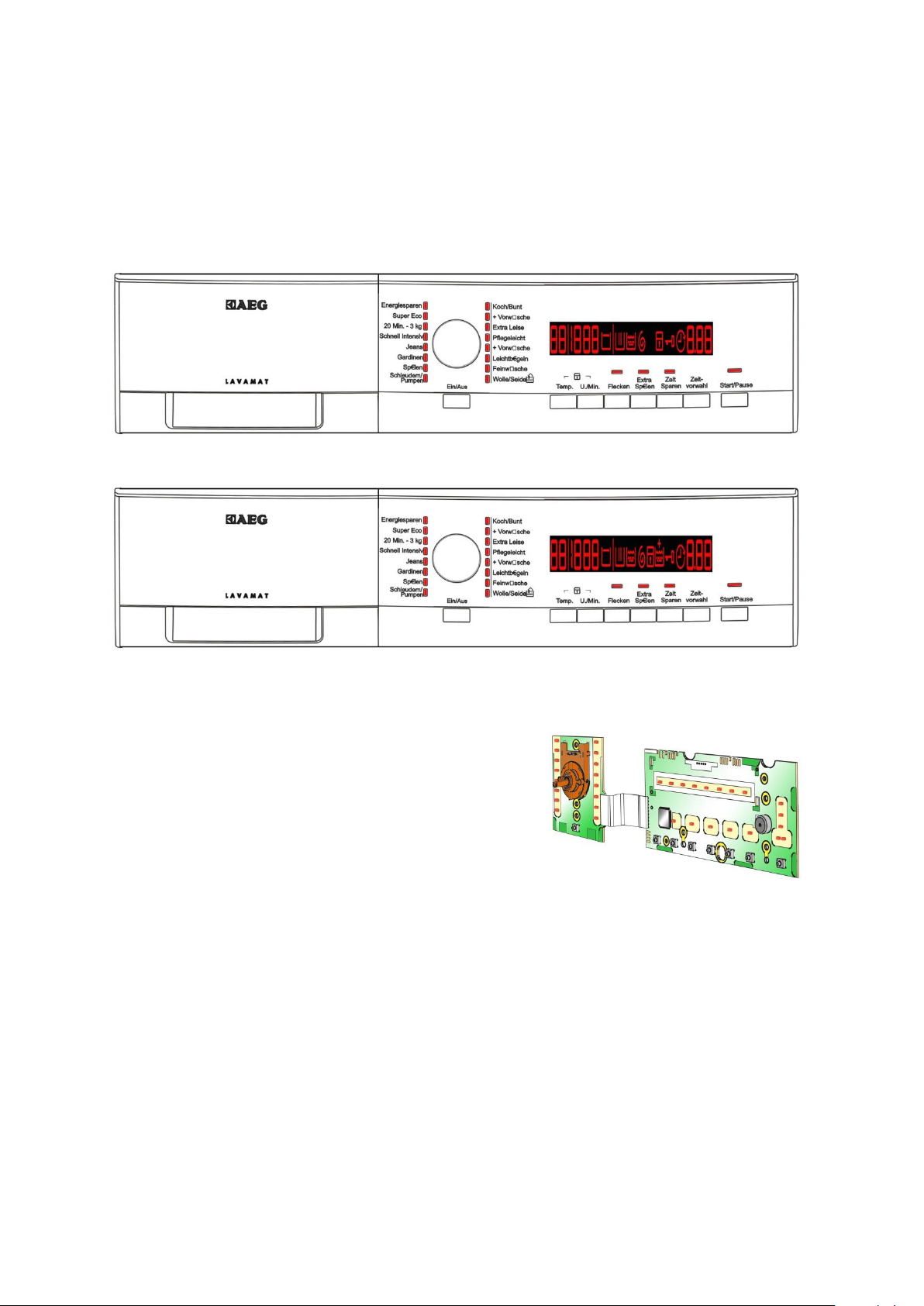
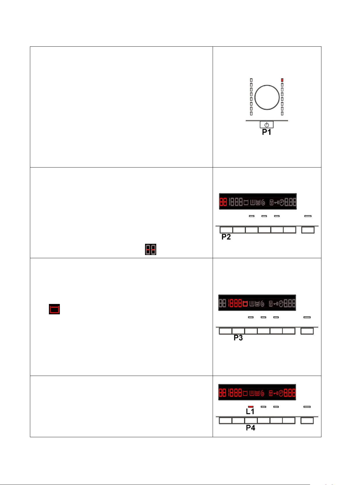
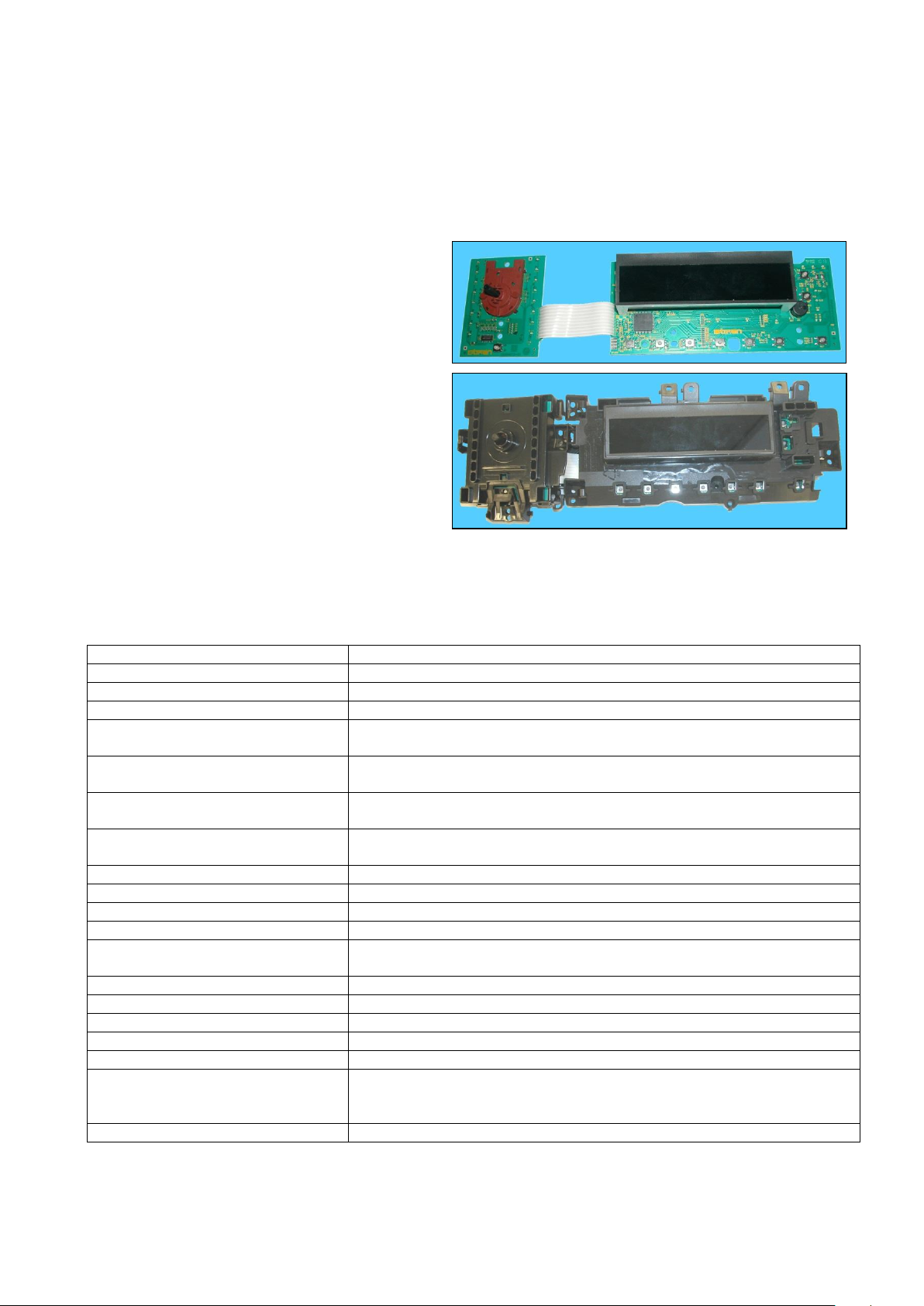
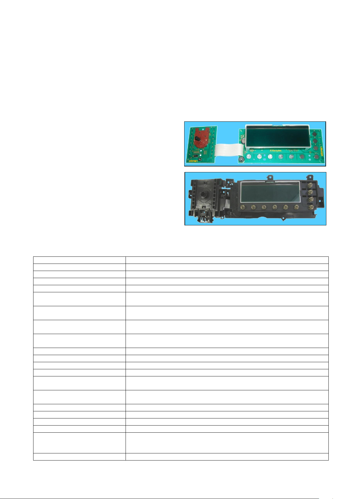
3.1 General characteristics
The EWX11831 and EWX14931 electronic control system consists of two circuit boards plus the motor control
system (inverter).
The control/display board, which is inserted in
a plastic container fixed to the control panel
(the figure shows: the display board with the side
socket in which the selector is fixed, connected
together by a flat cable, and the display board
assembly).
The main circuit board is positioned at the rear of the appliance and receives commands from the display
board, powers the electrical components as well as communicating with the motor control board (Inverter).
Technical Support - DMM 8/106 599 77 23-65 Rev. 03
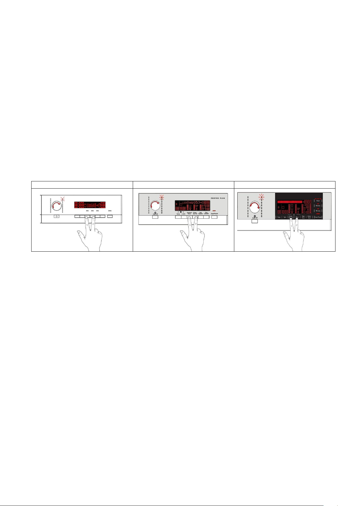
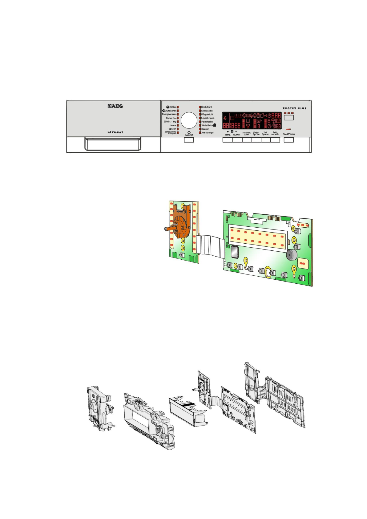
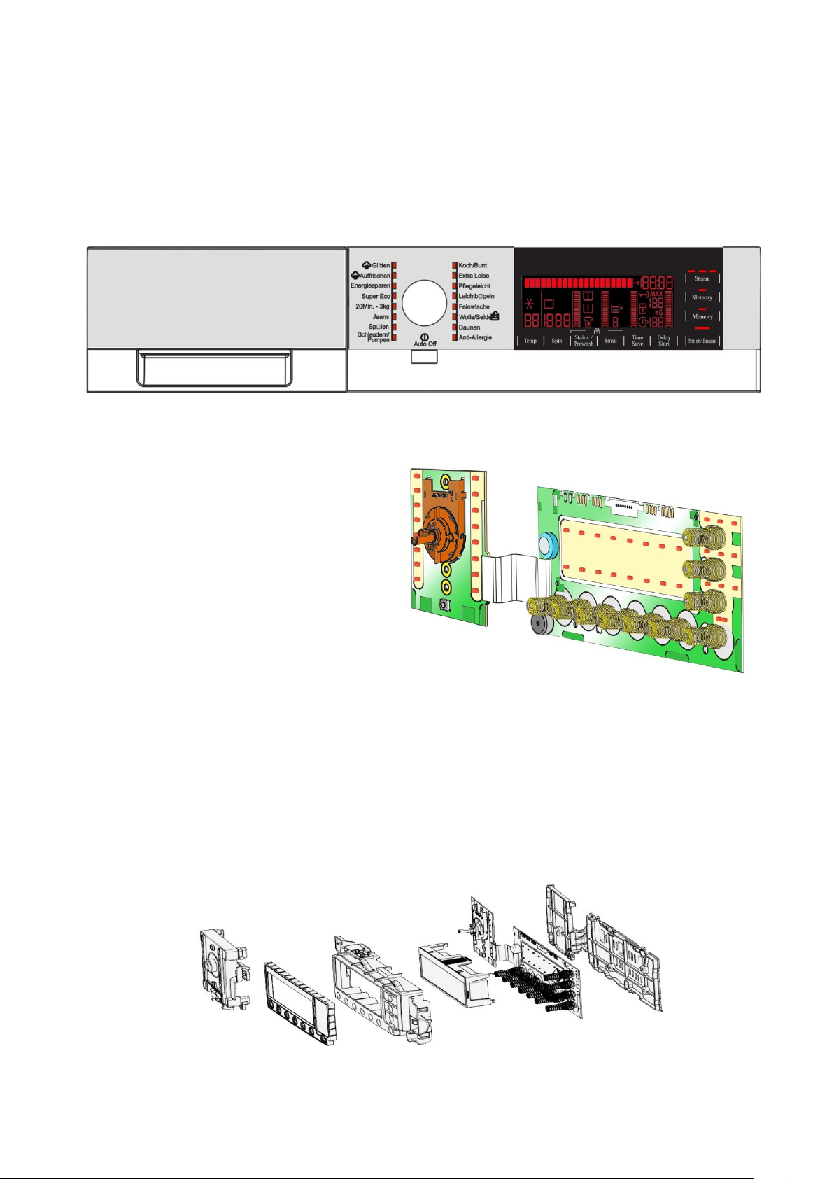
3.2 Control panel
3.2.1 Styling
Max. 8 buttons
16 position programme selector
20 LEDs
LCD
Initial production LCD version
Current production LCD version
Positioning of LEDs and buttons
Display board assembly, exploded view
1. Selector board protection
2. Display board protection
3. LCD screen
4. Display board and selector board
5. Rear protection
Technical Support - DMM 9/106 599 77 23-65 Rev. 03
3.2.2 Control panel configuration
Types of fabric
Cottons/linen, Synthetics, Delicates, Wool, Hand-wash, Shoes,
Jeans, Duvet, Silk.
Special programmes
Soak, Miniprogramme, Easy-Iron, Conditioner, Rinses,
Delicate rinses, Drain, Delicate spin, Spin.
Temperature
Normal, Maximum: the initial temperature is the one set for the
washing programme selected.
Spin
Normal, Minimum, Maximum.
Options (Normal/Possible)
Rinse Hold, Pre-wash, Stains, Extra Rinse, Normal, Daily,
Super quick, Spin reduction, No spin.
Programme phases
Pre-wash, Wash, Rinses, Spin, Delayed start.
The washing programmes, the functions of the selector knob and the various buttons vary
according to the model, since these are determined by the configuration of the appliance.
3.2.2.1 Programme selector (S1)
The selector used is of the HI-FI type (the dial has no index and
no reset position, the programme selected is indicated by the fact
that the corresponding LED lights up). The number of positions
cannot be configured. There are always 16 (in all three stylings)
and they are bound to the number of LEDs that indicate the
washing programmes.
The programmes can be configured to perform different washing
cycles (e.g.: water level, drum movement, no. of rinses and the
washing temperature to be selected according to the type of
garments).
The selector can be turned both clockwise and anti-clockwise.
For each programme, the compatible options and other
parameters are defined.
3.2.2.2 Programme configuration
The table below lists the parameters that can be used to define the washing programmes.
Technical Support - DMM 10/106 599 77 23-65 Rev. 03
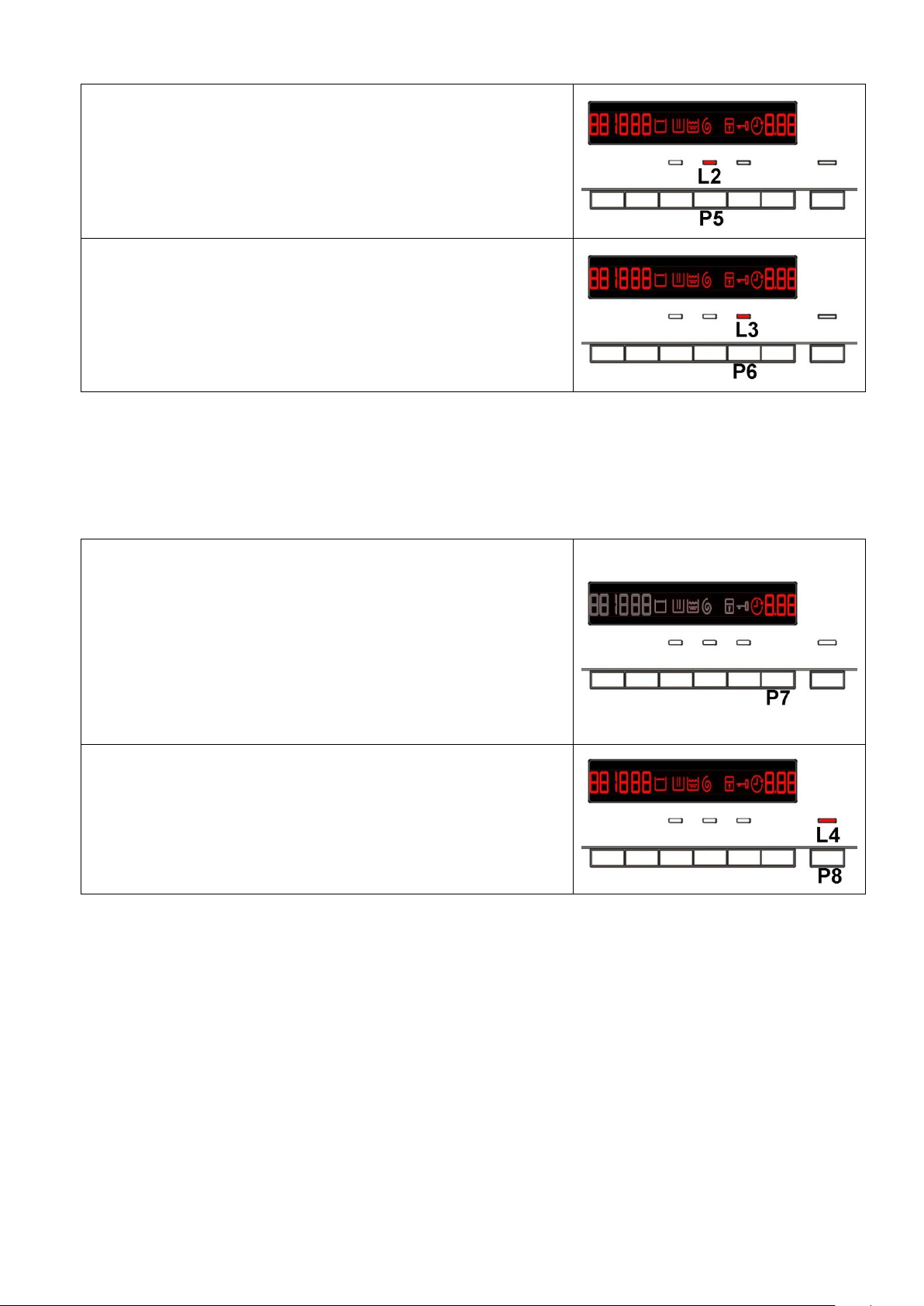
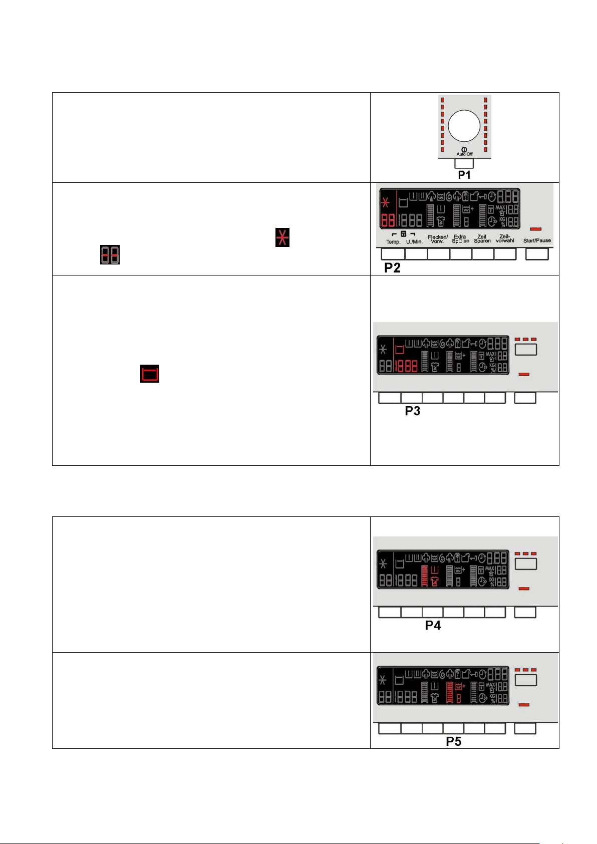
3.2.2.3 Pushbuttons – LEDs and LCD
Button no. 1: ON/OFF
This button is always present, whatever the styling.
Press it to turn the appliance on, at the same time the buzzer will
sound a tone (if enabled) and the LCD display lights up (the lighted
symbols are the ones for the programme).
To switch the appliance off, press and hold the button for
approximately 1 second, after which the buzzer will sound
a tone (if enabled), the LCD display and the LEDs will switch off,
all the options selected and any programme that is running will
be cancelled.
The operation of the ON/OFF depends on the configuration of the
main circuit board. It can cut the appliance off from the electricity
mains completely (0 Watt circuit) or set the appliance to low energy
consumption mode (without 0 Watt circuit) in which case you will
need to take the plug out of the socket to cut off the electricity supply
completely.
Button no. 2: TEMPERATURE
This is related to the part of the LCD display in which the washing
cycle temperature is shown.
The starting temperature shown on the LCD display is the one set
for the programme selected.
Press this button in sequence to lower the temperature, when the
lowest temperature is reached the selection will start again from
the highest one available for the programme.
The temperatures available (displayed in °C) are:
95°C, 60°C, 50°C, 40°C, 30°C, 20°C, cold cycle.
The cold cycle is displayed by two dashes .
Button no. 3: SPIN SPEED
This is related to the part of the LCD display in which the washing
cycle spin speed is shown.
The starting speed shown on the LCD display is the one set for
the programme selected.
Press the button in sequence to lower the speed. Once the lowest
speed selection is “Rinse hold” and the relevant symbol will light
up (if compatible with the programme selected). This is also
lit during the “Extra silent” programme.
The next selection will be the highest speed available for the
programme.
The spin speeds are: 1,600–1,400–1,200–1,000–800–600–
400– “Rinse Hold” cycle.
When no speed is selected, or the “Rinse Hold” cycle is selected,
the LCD display shows three dashes “ - - - “.
Button no. 4: OPTION
This button is configurable and is related to LED (L1). Depending
on the configuration of the appliance, it can perform the option of:
Stains
HOT & COLD water fill
Press this button to enable/disable the option associated with
it and turn LED L1 on/off respectively, at the same time the
programme time is updated (on the three digit display).
The functions of each button are defined by the configuration of the appliance.
Technical Support - DMM 11/106 599 77 23-65 Rev. 03
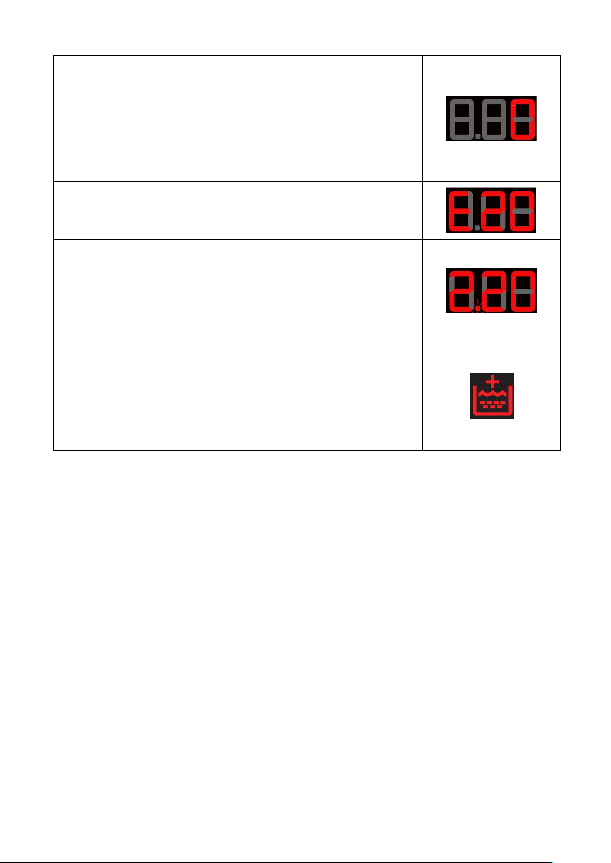
Button no. 5: OPTION
This button is related to LED (L2), and performs the option of:
Extra-rinse
Press this button to enable/disable the option associated with
it and turn the LED on/off respectively, at the same time the
programme time is updated (on the three digit display).
Button no. 6: OPTION
This button is related to LED (L3), and performs the option of:
Time Save
Press this button to enable/disable the option associated with
it and turn the LED on/off respectively, at the same time the
programme time is updated (on the three digit display).
Button no. 7: DELAYED START
This button is configurable and has the DELAYED START
function. During the programme selection phase, a delayed start
can be selected, from 30’ to 20 hours (30’ 60’ 90’ 2h
3h… 20h 0h) and the time is shown on the display;
during the final hour the time shown decreases minute by minute.
To cancel the delayed start time after the cycle has been started,
set the washing machine to pause using the START/PAUSE
button and cancel the option.
Button no. 8: START/PAUSE
This button is used to START the appliance or to PAUSE it.
It is related to LED L4 which flashes when the appliance is in
pause, whereas it produces a fixed light when the appliance
is performing a washing cycle.
The following options can also be configured on the appliances:
Time Save: with two 2 levels, corresponding to: Daily and Super Quick. Press once for the Daily function, the
relevant LED lights up, press twice for the Super Quick function, the relevant LED will remain on fixed and at
the same time the three digit display will vary the cycle time.
Stains and HOT and COLD Water are alternative options for the same button.
When the hot water solenoid is present, the relevant option is also configured.
Technical Support - DMM 12/106 599 77 23-65 Rev. 03
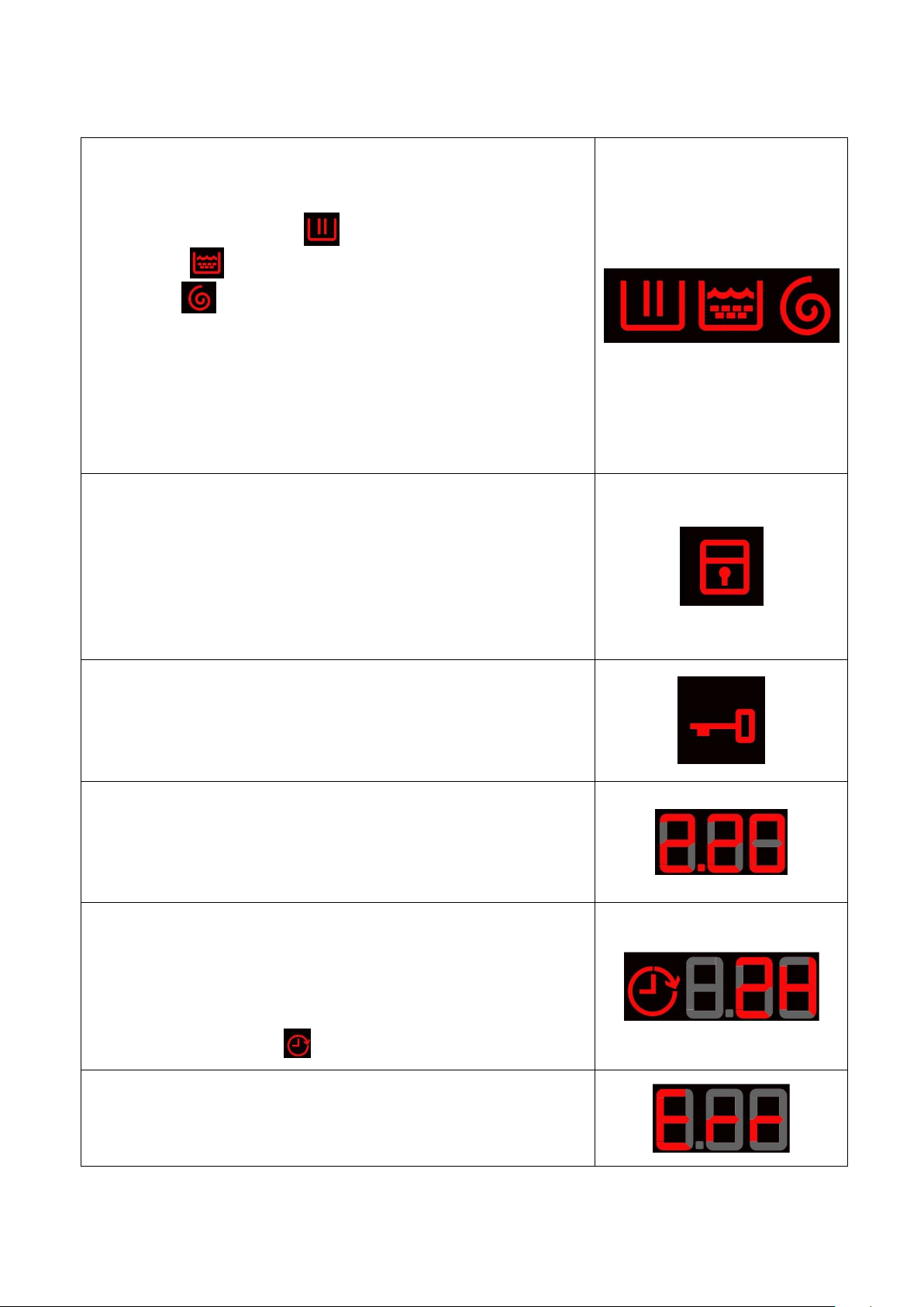
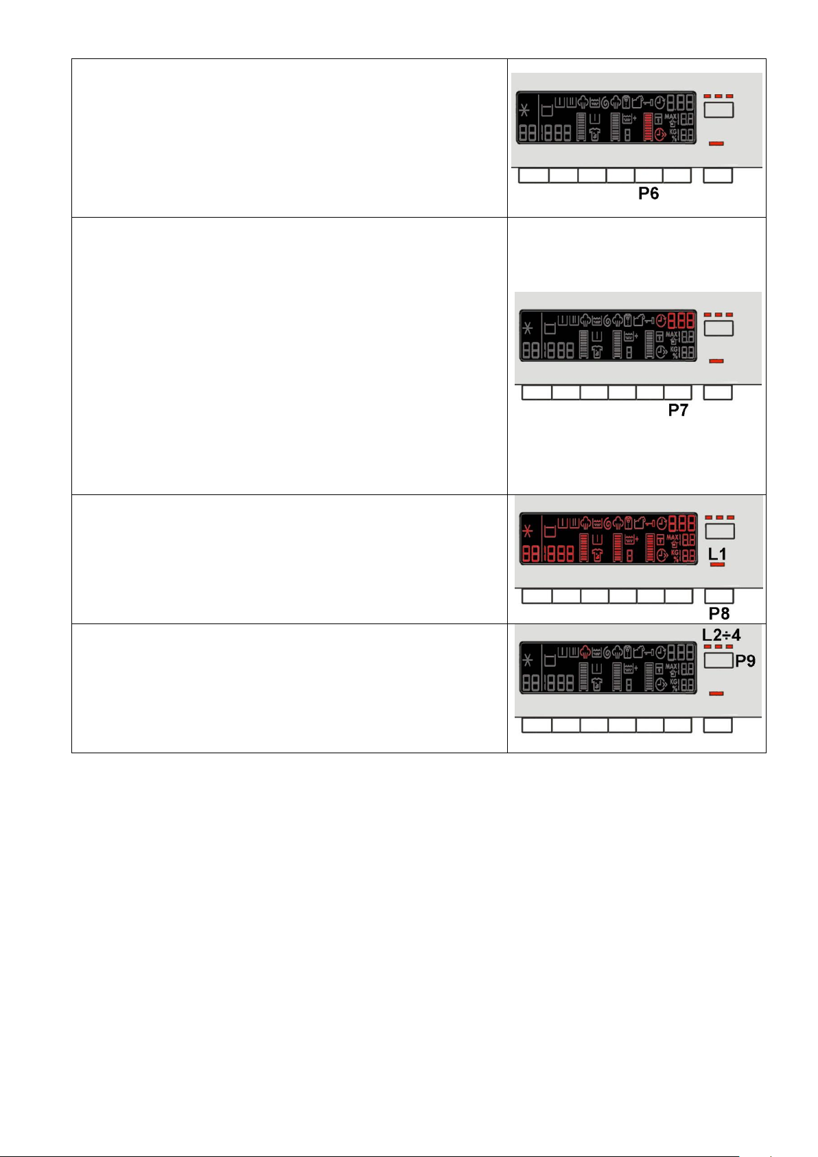
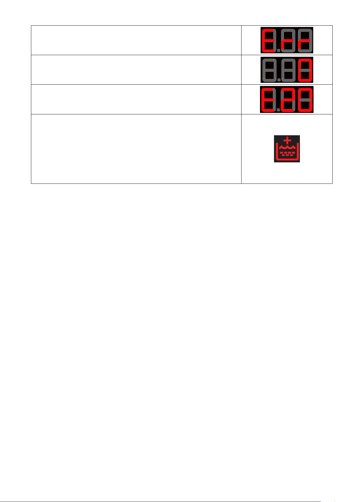
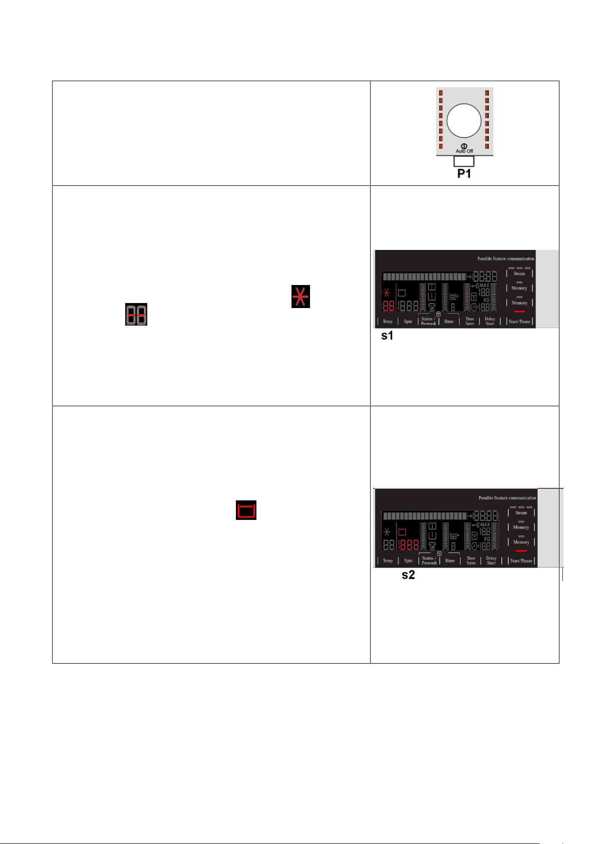
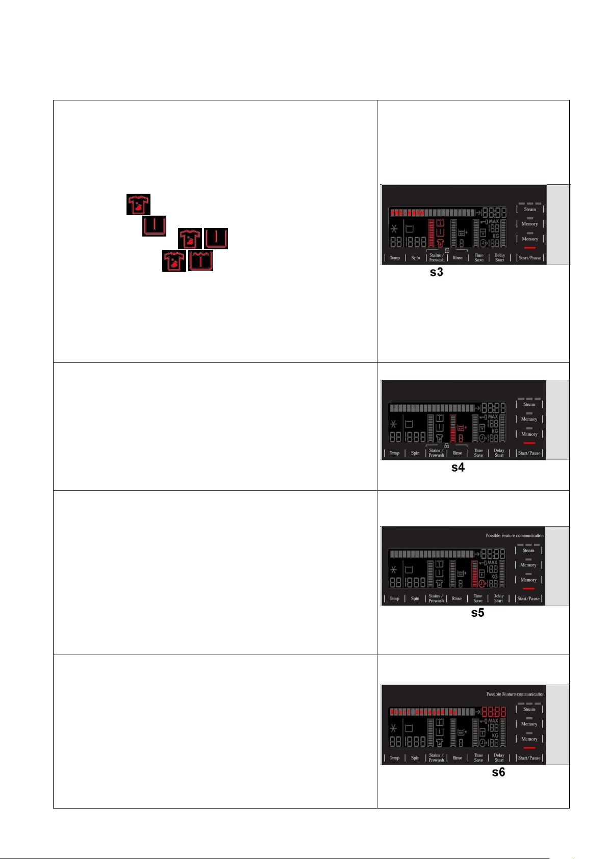
LCD
Programme phases:
The three icons shown have the following meanings, respectively:
Wash/Prewash/Steam
Rinse
Spin
They are lit during the setting phase to display which phases are
included in the programme.
During the programme the icon for the phase in progress flashes,
and when the phase has ended it remains lit continuously. The
same applies when the machine is in pause during the cycle.
The Wash/Prewash/Steam icon also lights up during the steam
phase, in appliances which feature this programme.
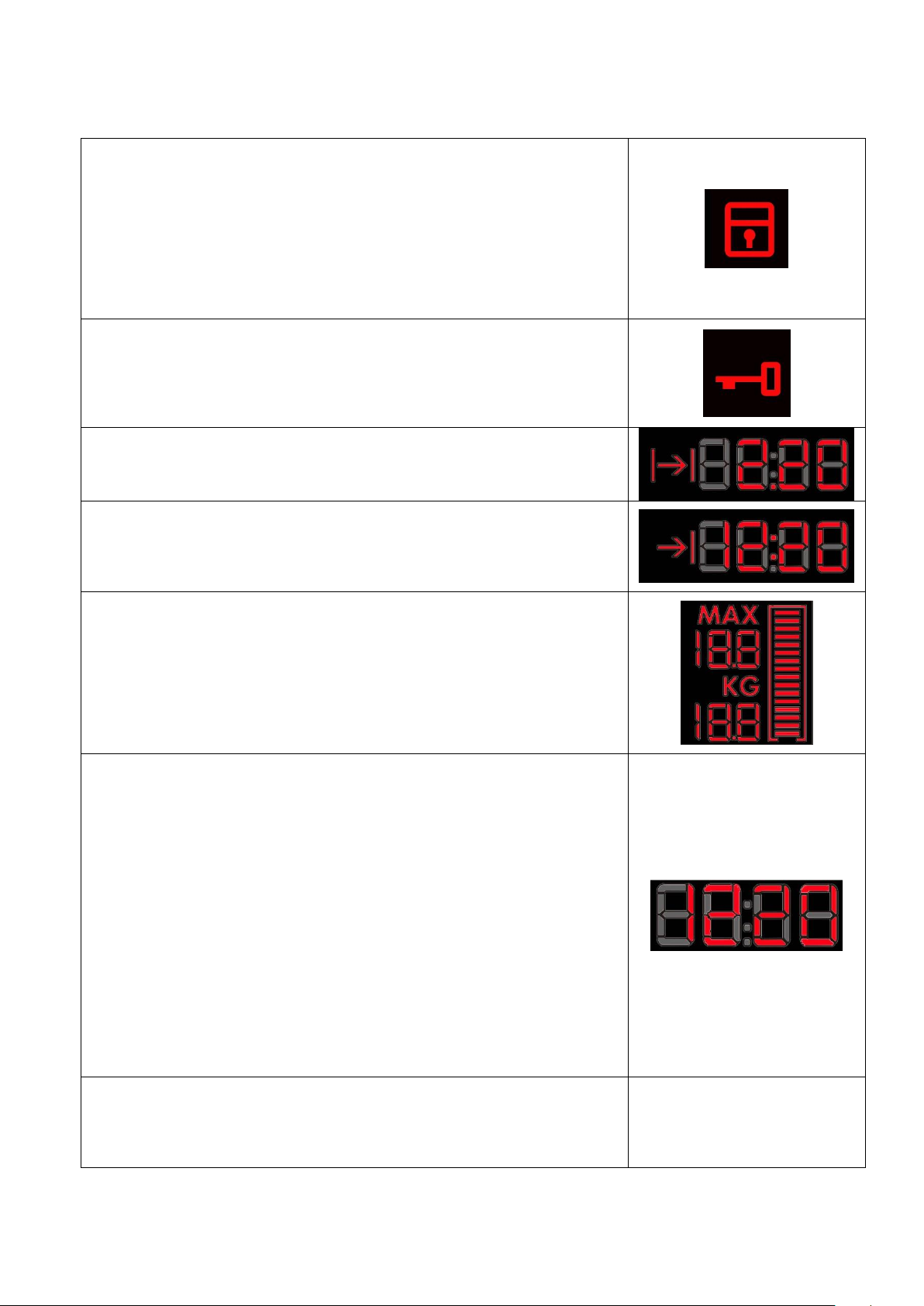
Padlock:
The icon lights up when the “child lock” is on.
It indicates that all the buttons are disabled to prevent children from
modifying, starting or pausing the cycle; Press any button or turn the
selector dial during its activation and the icon will flash.
To enable/disable this function, a key combination needs to be
pressed. It may be silk-screen printed on the control panel or
described in the instruction manual.
Door closed sensor:
Lights up when the safety device stops door opening and switches
off when the door can be opened.
Flashes when the device is about to unlock the door.
Washing programme time:
This appears after a washing programme has been selected. This
time corresponds to the time required for the maximum wash load
for each type of programme.
After the programme has started, the time decreases (and is
updated) minute by minute.
Delayed start:
Selected using the related button. After the START/PAUSE button is
pressed, the countdown starts and the delay time decreases hour by
hour, from a delay of 20 hours up to 2 hours ( 30’ 60’ 90’
2h 3h... 20 h 0h).
During the last 2 hours, it decreases by 30 mins at a time.
During delayed start, the icon remains permanently lit.
Selection incorrect:
Displays the flashing message “Err”, for one second.
Appears on selecting option that is incompatible with the programme
selected, or when the selector is turned while a cycle is running.
The information described below also appears on the LCD:
Technical Support - DMM 13/106 599 77 23-65 Rev. 03
End of cycle:
End of the programme is indicated by a permanently lit zero
(when the door can be opened).
Appliance stopping with water in the tub, at the end of Programmes
with the RINSE HOLD option, this is displayed by a permanently lit zero.
The LED indicating the door remains on and the LED of the START/PAUSE
button is turned off. The washing machine continues to operate, rotating
the drum once every 2 minutes.
Alarm code:
Indicates an anomaly during operation of the machine. Simultaneously
to the displaying of the code, the START/PAUSE button flashes.
Calculate amount of washing:
Only for appliances with PROPORTIONAL programmes.
After starting the washing programme the dot starts to flash. At this point
the washing machine calculates the amount of washing inside the drum.
When this phase ends the dot lights up fixed and the three digits display
the programme time.
Extra-rinse:
Appliances which do not feature the button and related LED for the Extra
rinse option can enable/disable this option by pressing a key combination
(which may be silk-screen printed on the control panel or described in the
instruction manual). This option is enabled/disabled during programme
selection and is confirmed by the related symbol being turned on/off.
The option remains enabled even after the appliance has been turned off
(for subsequent programmes).
Technical Support - DMM 14/106 599 77 23-65 Rev. 03
3.2.2.4 Buzzer
SERIES 7
SERIES 8
SERIES 9
This comprises a multi-tone buzzer and sounds in the following cases:
When the machine is turned on and off it emits two different tunes.
When a button is pressed it emits a short “Click”.
When the cycle ends this is indicated by a special sequence of “three long beeps” repeated at intervals of
15” for a total of 2 minutes.
In the event of a malfunction in the machine this is indicated by a special sequence of “three short beeps”
repeated 3 times at intervals of 15” for a total of 5 minutes.
All appliances are fitted with the buzzer, and leave the factory with the option enabled. To disable it use the
combination of keys.
The volume level is set in the factory and cannot be adjusted by the user.
When the buzzer is disabled (using the combination of keys) it only emits the short “Click” and the sequence
of “three short beeps” when an alarm is triggered.
During the programme selection phase, the buzzer can be enabled/disabled by pressing key combination
(which may be silk-screen printed on the control panel or described in the instruction manual), but the alarm
signalling remains enabled.
To enable it, press the buttons simultaneously for 5 seconds. A short beep will confirm that it has been enabled,
whereas two short beeps will confirm that it has been disabled.
Technical Support - DMM 15/106 599 77 23-65 Rev. 03
4 SERIES 8
No. buttons
Maximum 9 (6 options + start/pause + ON/OFF)
No. LEDs
Maximum 20 + LCD
Programme selector
16 positions (incorporated in the circuit board)
Serial port
DAAS-EAP communications protocol up to 115,200 baud
Power supply voltage
220/240 V
50/60 Hz (configurable)
Washing type
Traditional with “Eco-ball” sphere
Jet-System
Rinsing system
Traditional with “Eco-ball” sphere
Jet-System
Motor
Two-pole asynchronous (three-phase)
Three-phase synchronous
Spin speed
400÷1,600 rpm
Anti-unbalancing system
AGS
Cold water fill
1 solenoid valve with 1 inlet – 2 or 3 outlets
Hot water filling
1 solenoid valve with 1 inlet – 1 outlet
Detergent dispenser
3 compartments: prewash/stains, wash, fabric softeners
4 compartments: prewash, wash, stain remover, conditioners
Control of water level in the tub
Electronic/analogue pressure switch
Door safety interlock
Instantaneous
Heating element heat output
1,950 W with thermal fuses incorporated
Temperature check
NTC probe incorporated in the heating element
Buzzer
Traditional incorporated in the PCB
Sensors
Water fill gauge (2÷12 l/m flowmeter)
Water control
Weight sensor
Drum light
LED
4.1 General characteristics
The EWX11831 and EWX14931 electronic control system consists of two circuit boards, the motor control
system (inverter)
and in some appliances the weight sensor board.
The control/display board, which is inserted
in a plastic container fixed to the control
panel (the figure shows: the display board
with the side socket in which the selector is
fixed, connected together by a flat cable,
and the display board assembly).
The main circuit board is positioned at the rear of the appliance and receives commands from the display
board, powers the electrical components as well as communicating with the motor control board (Inverter)
and with the weight sensor where featured.
Technical Support - DMM 16/106 599 77 23-65 Rev. 03
4.2 Control panel
1 2 3
4
5
4.2.1 Styling
Max. 9/10 buttons
16 position programme selector
20 LEDs
LCD
Positioning of LEDs and buttons
Display board assembly, exploded view
1. Selector board protection
2. Display board protection
3. LCD screen
4. Display board and selector board
5. Rear protection
Technical Support - DMM 17/106 599 77 23-65 Rev. 03

4.2.1.1 Control panel configuration
The washing programmes, the functions of the selector knob and the various buttons vary
according to the model, since these are determined by the configuration of the appliance.
4.2.1.2 Programme selector (S1)
Description: see para. 3.2.2.1 on page 10
4.2.1.3 Programme configuration
Description: see para. 3.2.2.2 on page 10
Technical Support - DMM 18/106 599 77 23-65 Rev. 03
4.2.1.4 Pushbuttons – LEDs and LCD
Button no. 1: ON/OFF
Description: see Button no. 1 on page 11
Button no. 2: TEMPERATURE
See description on page 11
The only difference with version 7 is the representation of the cold
cycle, which is represented by the cold symbol and by two
dashes “ “ to replace the Digits.
Button no. 3: SPIN SPEED
This is related to the part of the LCD display in which the washing
cycle spin speed is shown.
The spin speed displayed initially is that configured for the chosen
programme.
Press the button in sequence to lower the speed. Once the lowest
speed has been reached, the next one is “Rinse Hold” and the
related light up (if compatible with the programme selected).
This is also lit during the “Extra silent” programme.
The next selection will be the highest speed available for the
programme.
The spin speeds are:
1,600–1,400–1,200–1,000–800–600–400– “Rinse Hold” cycle.
When no speed is selected, or the “Rinse Hold” cycle is selected,
the LCD display shows three dashes “ - - - “.
Button no. 4: OPTION
It is related to the part of the LCD display (see figure) where the
graphic bar and the symbols relating to the options are displayed,
depending on the chosen programme.
Press the button to light the graduated scale and the Stains
symbol lights simultaneously. If you continue to press it, the
Prewash symbol also lights up.
The selection order is as follows:
1. Stains
2. Pre-wash
3. Stains + Prewash
Button no. 5: OPTION
It is related to the part of the LCD display (see figure) showing:
the graphic bar, a digit and the “Extra rinse” symbol.
Press the button to light the graduated scale. The symbol for the
“Extra rinse” lights simultaneously, and the digit shows the
number of additional rinses to combine with the programme.
The number of rinses depends on the programme configuration.
The functions of each button are defined by the configuration of the appliance.
The settings described below not only have symbols, but they are also accompanied by a graphic bar within a
frame. If it is illuminated, this indicates that the option is enabled for the chosen programme, otherwise it is off.
When all its segments are lit, it will start from scratch again the next time it is pressed.
Technical Support - DMM 19/106 599 77 23-65 Rev. 03
Button no. 6: OPTION
It is related to the part of the LCD display (see figure) showing:
the graphic bar and the “Time save” option.
Press the button and half or all of the graduated scale may light
up, depending on the configuration of the button. The related
symbol also lights up simultaneously.
Press the button once and the chosen option is “Daily”.
Press the button twice and the chosen option is “Super Quick”.
Button no. 7: DELAYED START
It is related to the part of the LCD display (see figure) showing the
related symbol and the three digits.
Press the button in sequence to increase the delay by 30’ up to
2 hours, whereas from 2 hours to 20 hours, the increase is of
1 (one) hour every time the button is pressed. The symbol lights
and stays on for the entire delay phase.
During the programme selection phase, a delayed start can be
selected, from 30’ to 20 hours (30’ 60’ 90’ 2h 3h…
20h 0h) and the time is shown on the display; during the
final hour the time shown decreases minute by minute.
During the last hour, the time decreases minute by minute.
To cancel the delayed start time, after the cycle has started,
pause the washing machine using the related button and cancel
the option.
Button no. 8: START/PAUSE
This button is used to START the appliance or to PAUSE it.
It is related to LED L1, which flashes when the appliance is on
pause, whereas it is lit continuously during a washing cycle.
Button no. 9: STEAM (where featured)
Press this button in sequence to select from three different steam
intensity levels.
These are highlighted by the lighting of LEDs L2/L3/L4 and the
related symbol lighting on the LCD display.
Technical Support - DMM 20/106 599 77 23-65 Rev. 03
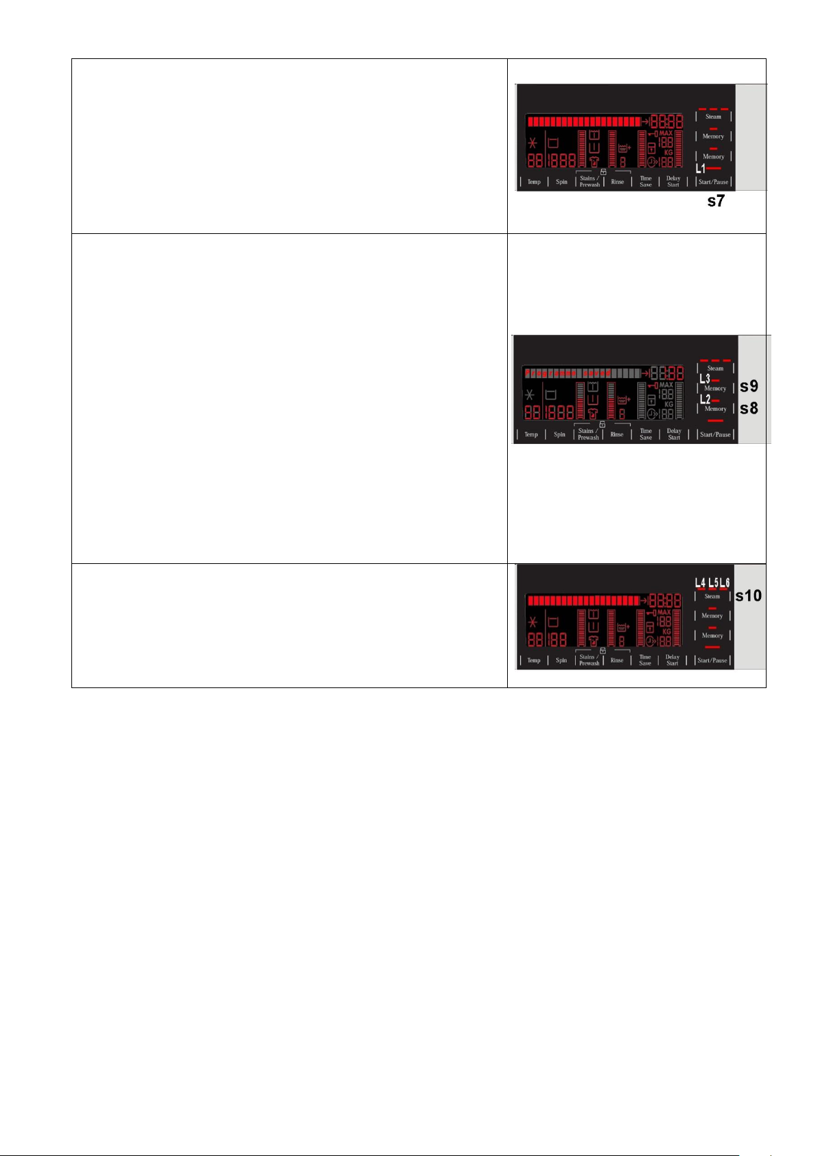
LCD
Programme phases:
The icons represented respectively mean:
1. Pre-wash
2. Wash
3. Rinse
4. Spin
5. Steam combined with the programme (where featured)
6. Rinse Hold
7. Excessive detergent
They light up during the programme setting where featured and during
their performance.
The icon representing the Overdosing lights up at the end of the cycle if
during the performance of the programme an excess production of foam
was detected.
1 2 3
4 5 6
7
Padlock:
The icon lights up when the “child lock” is on.
It indicates that all the buttons are disabled to prevent children from
modifying, starting or pausing the cycle.
To enable/disable this function, a key combination needs to be pressed.
It may be silk-screen printed on the control panel or described in the
instruction manual.
Door closed sensor:
Lights up when the safety device stops door opening and switches off
when the door can be opened.
Flashes when the device is about to unlock the door (with door interlock
with PTC, which needs one/two minutes to open).
Weight sensor:
Group of icons representing the weight information of the laundry inside
the drum.
Since they represent the maximum load possible, the actual weight of
the laundry inside the drum and the ratio of these two factors suggests
the quantity of detergent to pour into the detergent dispenser.
Description: see para. 5.2.1.7 on page 31
Washing programme time:
Description: see page 13
Delayed start:
Selected using the related button. After the START/PAUSE button is
pressed, the countdown starts and the delay time decreases hour by
hour, from a delay of 20 hours up to 2 hours 30’ 60’ 90’ 2h
3h... 20h 0h)
During the last 2 hours, it decreases by 30 mins at a time.
Press the button in sequence to increase the delay by 30’ up to 10 hours,
whereas from 10 hours to 20 hours, the increase is of 1 (one) hour every
time the button is pressed.
During the programme selection phase, a delayed start can be
selected, from 30’ to 20 hours (30’ 60’ 90’ 10h 11h…
20h 0h) and the time is shown on the display; during the final
hour the time shown decreases minute by minute.
during the last hour, the time decreases minute by minute.
To cancel the delayed start time, after the cycle has started, pause the
washing machine using the related button and cancel the option.
The information described below also appears on the LCD:
Technical Support - DMM 21/106 599 77 23-65 Rev. 03
Selection incorrect:
Description: see page 13
End of cycle:
Description: see page 14
Alarm code:
Description: see page 14
Extra-rinse:
Appliances which do not feature the button and related LED for the
Extra rinse option can enable/disable this option by pressing a key
combination (which may be silk-screen printed on the control panel or
described in the instruction manual). This option is enabled/disabled
during programme selection and is confirmed by the related symbol
being turned on/off.
The option remains enabled even after the appliance has been turned
off (for subsequent programmes).
4.2.1.5 Buzzer
Description: see para. 3.2.2.4. page 15
Technical Support - DMM 22/106 599 77 23-65 Rev. 03
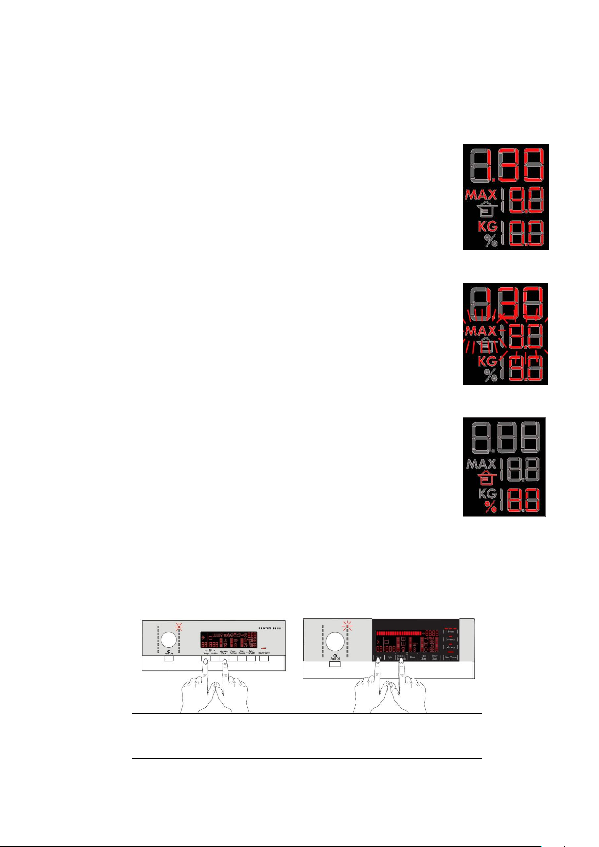
4.2.1.6 Weight sensor (where featured)
Series 8
Series 9
During the programme selection phase, the weight sensor can be enabled/
disabled by pressing a key combination as shown in the figure.
Appliances fitted with the weight sensor (inserted inside a shock absorber) are designed - thanks to the
LCD display - to inform the user of the weight of the laundry inside the drum while at the same time
suggesting the quantity of detergent to pour into the dispenser provided.
For it to operate, the appliance needs to be turned on and in selecting phase with the door open. When
the laundry is being placed inside the drum, the LCD displays the weight in kg with an accuracy of half
a kilogram.
The exact sequence to have the correct weight information is as follows:
The appliance must be turned off and the drum must be empty.
Turn the washing machine on, select the programme, choose the options, and if the door
was closed on starting, open it.
The LCD displays the maximum declared weight for the selected programme and 0.0 kg
the weight of the laundry inside the drum (empty drum). At the same time the laundry is
placed in the drum, the LCD display updates the digits relating to the time until the end
of the programme.
In the event of an overload in a programme (Cottons), the LCD display will continue to show the maximum
weight without warning that the load is excessive.
Whereas in other programmes (Synthetics, delicates, special programmes and in
particular the drying programmes) if the weight exceeds by only 1 kg or more, the
symbol “MAX” will begin to flash, together with the weight of the maximum load allowed.
In some cases, you will have to take some laundry out so that the symbol “MAX” and
the maximum weight allowed stop flashing and to guarantee optimum washing
performance.
Once the laundry has been loaded, close the door, the LCD display cancels all the weight details and displays
the quantity of detergent to be poured into the dispenser.
The representation consists of: a measuring cup, a number and the symbol for the
percentage.
The number displayed represents the percentage detergent to pour into the dispenser,
considering 100% to be the quantity required for the maximum load for the chosen
programme (value that remains fixed even in the case of an overload).
Once the detergent has been poured in, and the START/PAUSE button has been
pressed, the washing cycle will begin. The information about the weight of the laundry
and the percentage detergent disappears and will not be displayed again.
4.2.1.6.1 Enabling/Disabling the weight sensor
Technical Support - DMM 23/106 599 77 23-65 Rev. 03
5 SERIES 9
No. buttons
Max 1 (ON/OFF)
No. of sensors
Max 10 (options+start/pause+ memories)
No. LEDs
Maximum 22 + LCD
Programme selector
16 positions (incorporated in the circuit board)
Serial port
DAAS-EAP communications protocol up to 115,200 baud
Power supply voltage
220/240 V
50/60 Hz (configurable)
Washing type
Traditional with “Eco-ball” sphere
Jet-System
Rinsing system
Traditional with “Eco-ball” sphere
Jet-System
Motor
Two-pole asynchronous (three-phase)
Three-phase synchronous
Spin speed
400÷1,600 rpm
Anti-unbalancing system
AGS
Cold water fill
1 solenoid valve with 1 inlet – 2 or 3 outlets
Hot water filling
1 solenoid valve with 1 inlet – 1 outlet
Detergent dispenser
3 compartments: prewash/stains, wash, fabric softeners
4 compartments: prewash, wash, stain remover, conditioners
Control of water level in the
tub
Electronic/analogue pressure switch
Door safety interlock
Instantaneous
Heating element heat output
1,950 W with thermal fuses incorporated
Temperature check
NTC probe incorporated in the heating element
Buzzer
Traditional incorporated in the PCB
Sensors
Water fill gauge (2÷12 l/m flowmeter)
Water control
Weight sensor
Drum light
LED
5.1 General characteristics
The SERIES 9 has a single ON/OFF button, all the other choices/adjustments are made by skimming your
finger over the touch sensors, which replace the buttons used so far.
In the event of problems with the touch sensors (difficulty selecting/adjusting them), clean and dry the display
and do not wear gloves when setting the chosen programme.
The EWX11831 and EWX14931 electronic control system consists of two circuit boards, the motor control
system (inverter)
and in some appliances the weight sensor board.
The control/display circuit board, inserted in
a plastic box, secured to the control panel (the
figure illustrates: the display board with the side
socket in which the selector is fixed, connected
together by a flat cable, and the display board
assembly).
The main circuit board is positioned at the rear of the appliance and receives commands from the display
board, powers the electrical components as well as communicating with the motor control board (Inverter)
and with the weight sensor where featured.
Technical Support - DMM 24/106 599 77 23-65 Rev. 03
5.2 Control panel
1
2
3
4
5
6
5.2.1 Styling
Max buttons 1
Max sensors 10
16 position programme selector
22 LEDs
LCD
Positioning of LEDs and buttons
Display board assembly, exploded view
1. Selector board protection
2. Seal
3. Display board protection
4. LCD screen
5. Display board and selector board
6. Rear protection
Technical Support - DMM 25/106 599 77 23-65 Rev. 03
5.2.1.1 Control panel configuration
Language Configuration
Time Configuration
Once the appliance has been turned on during the
selecting phase you are given the opportunity to change
language.
Touch the sensors as shown in the figure, and for the
next 3 seconds you can choose your new language.
Once the appliance has been turned on during the
selecting phase you are given the opportunity to set
the time.
Touch the sensors as shown in the figure, and for the
next 3 seconds you can modify the time.
The washing programmes, the functions of the selector knob and the various buttons vary according
to the model, since these are determined by the configuration of the appliance.
5.2.1.2 Initial Start up
The first time the appliance is turned on and after every diagnostic cycle, the language and time need to be set.
5.2.1.2.1 Set Language
The first time the appliance is turned on or after a diagnostic cycle, the text line prompts you to turn the selector
to choose your language (the language displayed is the one of the silk screen printed control panel) for
approximately 3 seconds. Once you have chosen your language, after another 3 seconds you will be prompted
to touch the START/PAUSE sensor to confirm your choice.
If the appliance is turned off before you confirm your choice, the next time it is turned on, you will again be
prompted to choose your language.
5.2.1.2.2 Setting the time of day
After the language has been selected, the text line shows “Time of day” prompting you to set the time.
After approximately 3 seconds, you will be prompted to turn the selector, which will change the time by an hour
(in the digits) every time it is moved. Once the correct time has been set, confirm by pressing the
START/PAUSE sensor.
The digits relating to the minutes start to flash. Again, turn the selector dial to adjust them too and confirm with
the START/PAUSE sensor. Now the time of day has also been set.
To change the language or time, see the key combination in the table below.
5.2.1.3 Programme selector (S1)
Description: see para. 3.2.2.1 on page 10
5.2.1.4 Programme configuration
Description: see para. 3.2.2.2 on page 10
Technical Support - DMM 26/106 599 77 23-65 Rev. 03
5.2.1.5 Pushbuttons – LEDs and LCD
Button no. 1: ON/OFF
Description: see Button no. 1 on page 11
Unlike the other versions, in the SERIES 9, after pressing the
ON/OFF button the LCD displays the time of day (for two seconds
to allow the user to check it and if necessary update it) followed
by the programme information.
Sensor no. 1: TEMPERATURE
It is related to the part of the LCD display (see figure) where the
temperature of the washing cycle is shown.
The initial temperature displayed is that set for the chosen
programme.
Touch the sensor with your finger to lower it. Once you have
reached the lowest one, the selection starts off again from the
highest temperature.
The cold cycle is represented by the cold symbol and by
two dashes “ - - “ to replace the Digits.
The temperatures available (displayed in °C) are:
95°C, 60°C, 50°C, 40°C, 30°C, 20°C, cold cycle.
Concurrently with the display of the temperature in degrees, the
name of the selected function appears at the top of the display in
the text line.
Sensor no. 2: SPIN SPEED
It is related to the part of the LCD display (see figure) where the
spin speed of the washing cycle is shown.
The initial speed shown on the LCD display is that configured for
the selected programme.
Touch the sensor with your finger to lower the speed. Once the
lowest speed has been reached, the next selection is
“Rinse Hold” and the related symbol lights up
(where compatible with the chosen programme), which is also lit
during the “Extra silent” programme.
The next selection will be the speed configured for the programme.
The spin speeds are:
1,600–1,400–1,200–1,000–800–600–400– “Rinse Hold” cycle.
When no speed is selected, or the “Rinse Hold” cycle is selected,
the LCD display shows three dashes “ - - - “.
Concurrently with the display of the spin speed in rpm, the name
of the selected function appears at the top of the display (in the
text line).
The functions of each button are defined by the configuration of the appliance.
Technical Support - DMM 27/106 599 77 23-65 Rev. 03
The settings described below not only have the symbols of the options, but they are also accompanied by a
Sensor no. 3: OPTION
It is related to the part of the LCD display (see figure) where a
graphic bar and the symbols relating to the options are displayed,
depending on the chosen programme.
Touch the sensor with a finger and the graphic bar starts to light
up. The symbol for Stains is turned on at the same time.
As you continue, the Prewash symbol lights up.
The selection order is as follows:
1. Stains
2. Pre-wash
3. Stains + Prewash
4. Stains + Soak
5. No Option
It may happen that it is not possible to select the option(s) where
the stains item is displayed, due to the washing temperature being
too low, and consequently the options are skipped.
Concurrently to the displaying of the symbol for the option, as the
graphic bar is gradually illuminated, the name of the chosen
option is displayed in the text line in the top left.
Sensor no. 4: EXTRA RINSE
It is related to the part of the LCD display (see figure) showing: the
graphic bar, a digit and the symbol for the “Extra rinse” option.
Touch the sensor with your finger and the graphic bar begins to
light up. Concurrently, the symbol lights up and you can choose
the number of rinses to add to the programme, which are
displayed by the digit (depending on the programme).
Concurrently to the displaying of the symbol for the option, as the
graphic bar is gradually illuminated, the name of the option is
displayed in the text line in the top left.
Sensor no. 5: OPTION
It is related to the part of the LCD display (see figure) showing:
the graphic bar and the “Time save” option.
Touch the sensor with your finger, half or all of the graduated
scale may light up, depending on the configuration and the
related symbol also lights simultaneously.
Touch once
and the chosen option is “Daily”.
touch again and the graduated scale lights up completely
the chosen option is “Super Quick”.
Concurrently to the displaying of the symbol for the option, as the
graphic bar is gradually illuminated, the name of the chosen
option is displayed in the text line in the top left.
Sensor no. 6: DELAYED START
It is related to the part of the LCD display (see figure) showing:
the four digits and the text bar.
Touch the sensor with your finger. The LCD display is updated
according to the status of the door: if the door is open, the words
“Start delayed by” are displayed and the delay time is displayed in
the digits for approximately 5 seconds, whereas if the door is
closed, the words “Programme ending at” are displayed along
with the programme end time.
During the last hour, the time decreases minute by minute.
To cancel the delayed start time, after the cycle has started,
pause the washing machine using the related sensor (7) and
cancel the option.
graphic bar within a frame. If the latter is lit, this means the option is enabled for the chosen programme.
Otherwise it remains off.
When all its segments are lit, it will start from scratch again the next time it is pressed.
Technical Support - DMM 28/106 599 77 23-65 Rev. 03
Sensor no. 7: START/PAUSE
Touch the sensor with your finger to START or PAUSE the
appliance.
It is related to LED (L1), which flashes when the appliance is on
pause, whereas it is lit continuously when the appliance is
performing a washing cycle.
Sensor no. 8/9: MEMORY
Touch one of these sensors with your finger to store or recall
a stored programme.
When the selected programme has been optimised with the
desired options, it can be saved in one of the two memories by
touching the related sensor (s8/9) for approximately 3 seconds.
The buzzer “beeps” once and the LED (L2/3) corresponding to
the memory lights up and the words “Programme saved” are
displayed in the text line to show that the operation was
successful. To recall the stored programme, simply touch the
sensor (s8/9) of the memory concerned, the corresponding LED
(L2/3) lights up and the LCD displays the settings of the
programme saved (selector LED, options, time left and the words
“Memory programme” are displayed in the text line for
approximately 3 seconds).
If a sensor of the memory which contains no stored programmes
is touched, the buzzer “beeps” once and the corresponding LED
stays on and the words “Memory is empty” are displayed in the
text line for approximately 3 seconds.
Sensor no. 10: STEAM (where featured)
Touch this sensor with your finger in sequence to select among
the three steam intensity levels shown by the lighting of LEDs
L4/L5/L6.
The text line displays the status of the option.
Technical Support - DMM 29/106 599 77 23-65 Rev. 03
LCD
Padlock:
The icon lights up when the “child lock” is on.
To indicate that all the sensors are disabled to prevent children from
modifying, starting or pausing the cycle.
A sensor combination needs to be pressed to activate/deactivate it.
It may be silk-screen printed on the control panel or described in the
instruction manual.
Door closed sensor:
Lights up when the safety device stops door opening and switches off
when the door can be opened.
It flashes when the device is about to unlock the door (it is noticed with
PTC delaying devices, which need one or two minutes to open).
Cycle time:
It lights up to indicate the cycle time
Time left:
It lights up to indicate the time left until the end of the cycle.
Weight sensor:
Group of icons representing the weight information of the laundry inside
the drum.
Since they represent the maximum load possible, the actual weight of
the laundry inside the drum and suggests the quantity of detergent to
pour into the detergent dispenser.
Description: see para. 5.2.1.7 on page 31
Delayed start:
Selected on the related sensor. After the START/PAUSE button is
pressed, the countdown starts and the delay time decreases hour by
hour, from a delay of 20 hours up to 2 hours( 30’ 60’ 90’ 2h
3 h... 20 h 0 h)
During the last 2 hours, it decreases by 30 mins at a time.
Touch the sensor in sequence to increase the delay by 30’ up to
10 hours, whereas from 10 hours to 20 hours, the increase is of
1 (one) hour every time the button is pressed.
During the programme selection phase, a delayed start can be
selected, from 30’ to 20 hours (30’ 60’ 90’ 10h 11h…
20h 0h) and the time is shown on the display; during the final hour
the time shown decreases minute by minute.
To cancel the delayed start time, after the cycle has started, pause the
washing machine using the related button and cancel the option.
Selection incorrect:
The words “Not possible” are displayed in the text line.
The information described below also appears on the LCD:
Technical Support - DMM 30/106 599 77 23-65 Rev. 03
 Loading...