

Electrolux MC1751E, EMS1760X, ZM175ST, ZM176ST, QN4025 Service Manual
...
SOI 01.05 FV 599 36 78-06
SERVICE MANUAL
MICROWAVE OVENS
ELECTROLUX HOME PRODUCTS
Corso Lino Zanussi,30
Publication No.
I - 33080 PORCIA /PN (ITALY)
599 36 78-06
Tel +39 0434 394850
Fax +39 0434 394096
SOI
Edition: 01.2005
EN/SERVICE/FV
Microwave Oven
(Compact Solo)
MC1751E/MC1761E (EU)
MC1751E/MC1761E (UK)
EMS1750X/EM1760X (UK)
QN4025/QN4026
(SCANDINAVIA)
JMW1051/JMW1061 (A,D)
MOA4217 (D,K)

SOI 01.05 FV 2/33 599 36 78-06

SOI 01.05 FV 3/33 599 36 78-06
TABLE OF CONTENTS
CAUTION, MICROWAVE RADIATION / GENERAL INFORMATION .............................................4
SERVICING......................................................................................................................................3
PRODUCT SPECIFICATIONS.........................................................................................................6
APPEARANCE VIEW.......................................................................................................................7
OPERATING SEQUENCE .............................................................................................................10
FUNCTION OF IMPORTANT COMPONENTS.............................................................................. 12
TROUBLESHOOTING CHART......................................................................................................13
TEST PROCEDURE ......................................................................................................................14
CONTROL PANEL ASSEMBLY.....................................................................................................22
COMPONENT REPLACEMENT AND ADJUSTMENT PROCEDURE..........................................24
MICROWAVE MEASUREMENT....................................................................................................30
TEST DATA A GLANCE / WIRING / RE-WIRING .........................................................................31
SCHEMATIC DIAGRAMS ..............................................................................................................32
PICTORIAL DIAGRAM................................................................................................................... 33

SOI 01.05 FV 4/33 599 36 78-06
CAUTION
CAUTION
MICROWAVE RADIATION
Personnel should not be exposed to the microwave energy which may radiate from the
magnetron or other microwave generating devices if it is improperly used or connected. All
input and output microwave connections, waveguides, flanges and gaskets must be secured.
Never operate the device without a microwave energy absorbing load attached.
Never look into an open waveguide or antenna while the device is energized.
GENERAL IMPORTANT INFORMATIONS
This Manual has been prepared to provide Service Engineers with Operation and Service Information.
It is recommended that service engineers carefully study the entire text of this manual, so they will be
qualified to render satisfactory customer service.
WARNING
Note: The parts marked "*" are used at voltage
more than 250V. (Schematic Diagrams).
WARNING
Never operate the oven until the following points are ensured.
(A) The door is tightly closed.
(B) The door and oven hinges are not defective.
(C) The door packing is not damaged.
(D) The door is not deformed or warped.
(E) There is not any other visible damage with the oven.
Servicing and repair work must be carried out only by trained
Service Engineers.
All the parts marked ”*” on schematic diagrams are used at
voltages more
than 250V.
Removal of the outer wrap gives access to potentials above
250V.
All the parts marked "*" on the schematic diagrams may cause
undue microwave exposure, by themselves, or when they are
damaged, loosened or removed.
SOI 01.05 FV 5/33 599 36 78-06
SERVICING
WARNING TO SERVICE PERSONNEL
Microwave ovens contain circuitry capable of producing very high voltage and current.
Contact with the following parts will result in electrocution
High voltage capacitor, High Voltage transformer, Magnetron, High voltage rectifier assembly,
High voltage wires.
REMEMBER TO CHECK 3D
1) Disconnect the supply.
2) Door opened, and wedged open.
3) Discharge high voltage capacitor.
WARNING AGAINST THE CHARGE OF THE
HIGH VOLTAGE CAPACITOR
The high-voltage capacitor remains charged about
60seconds after the oven has been switched off.
Wait for 60 seconds and then short-circuit the
connection of the high-voltage capacitor (that is, of
the connecting lead of the high-voltage rectifier)
against the chassis with the use of an insulated
screwdriver.
It is recommended that wherever possible faultfinding is carried out with the supply disconnected. It
may in, some cases, be necessary to connect the
supply after the outer case has been removed, in this
event carry out 3D checks and then disconnect the
leads to the primary of the power transformer. Ensure
that these leads remain isolated from other
components and the oven chassis. (Use insulation
tape if necessary.) When the testing is completed
carry out 3D checks and reconnect the leads to the
primary of the power transformer.
REMEMBER TO CHECK 4R
1) Reconnect all leads removed from components
during testing.
2) Replace the outer case (cabinet).
3) Reconnect the supply.
4) Run the oven. Check all functions.
Microwave ovens should not be run empty. To test
for the presence of microwave energy within a cavity,
place a cup of cold water on the oven turntable, close
the door and set the power to HIGH and set the
microwave timer for two (2) minutes. When the two
minutes has elapsed (timer at zero) carefully check
that the water is now hot. If the water remains cold
carry out 3D checks and re-examine the connections
to the component being tested.
When all service work is completed, and the oven is
fully assembled, the microwave power output should
be checked and a microwave leakage test carried
out.
When troubleshooting the microwave oven, it is
helpful to follow the Sequence of Operation in
performing the checks.
Many of the possible causes of trouble will require
that a specific test be performed. These tests are
given a procedure letter which will be found in the
"Test Procedure" section.
IMPORTANT:
If the oven becomes inoperative
because of a blown fuse F1 in the
monitored latch switch - monitor
switch - circuit, check the
monitored latch switch and monitor
switch and before replacing the
fuse F1.
GENERAL INFORMATION
WARNING
THIS APPLIANCE MUST BE EARTHED
IMPORTANT
THE WIRES IN THIS MAINS LEAD ARE COLOURED IN ACCORDANCE WITH THE FOLLOWING
CODE:
GREEN-AND-YELLOW : EARTH
BLUE : NEUTRAL
BROWN : LIVE
As part of our policy of continuous improvement, we reserve the right to
alter design and specifications without notice
SOI 01.05 FV 6/33 599 36 78-06
PRODUCT SPECIFICATIONS
SPECIFICATION
ITEM DESCRIPTION
Power Requirements 230 Volts(EU)/230-240 Volts(UK)
50 Hertz
Single phase, 3 wire earthed
Power Consumption 1.2 kW
Power Output
800W watts nominal of RF microwave energy
(measured by way of IEC 60705)
Operating frequency of 2450 MHz
Case Dimensions
Width 454mm(including screws)
Height 357mm (including foot)
Depth 320mm
Cooking Cavity Dimensions
Width 285mm
Height 202mm
Depth 298mm
Turntable diameter 272mm
Jog/Touch Control System
Clock (1.00-12.59 or 0.00-23.59) - 12HR or 24HR
setting
Microwave Power for Variable Cooking
Repetition Rate;
HIGH .......................... Full power throughout
the cooking time
MEDIUM HIGH .......... approx. 70% of Full
Power
MEDIUM .................... approx. 50% of Full
Power
MEDIUM LOW............ approx. 30% of Full
Power
LOW .........................
approx. 10% of Full
Power
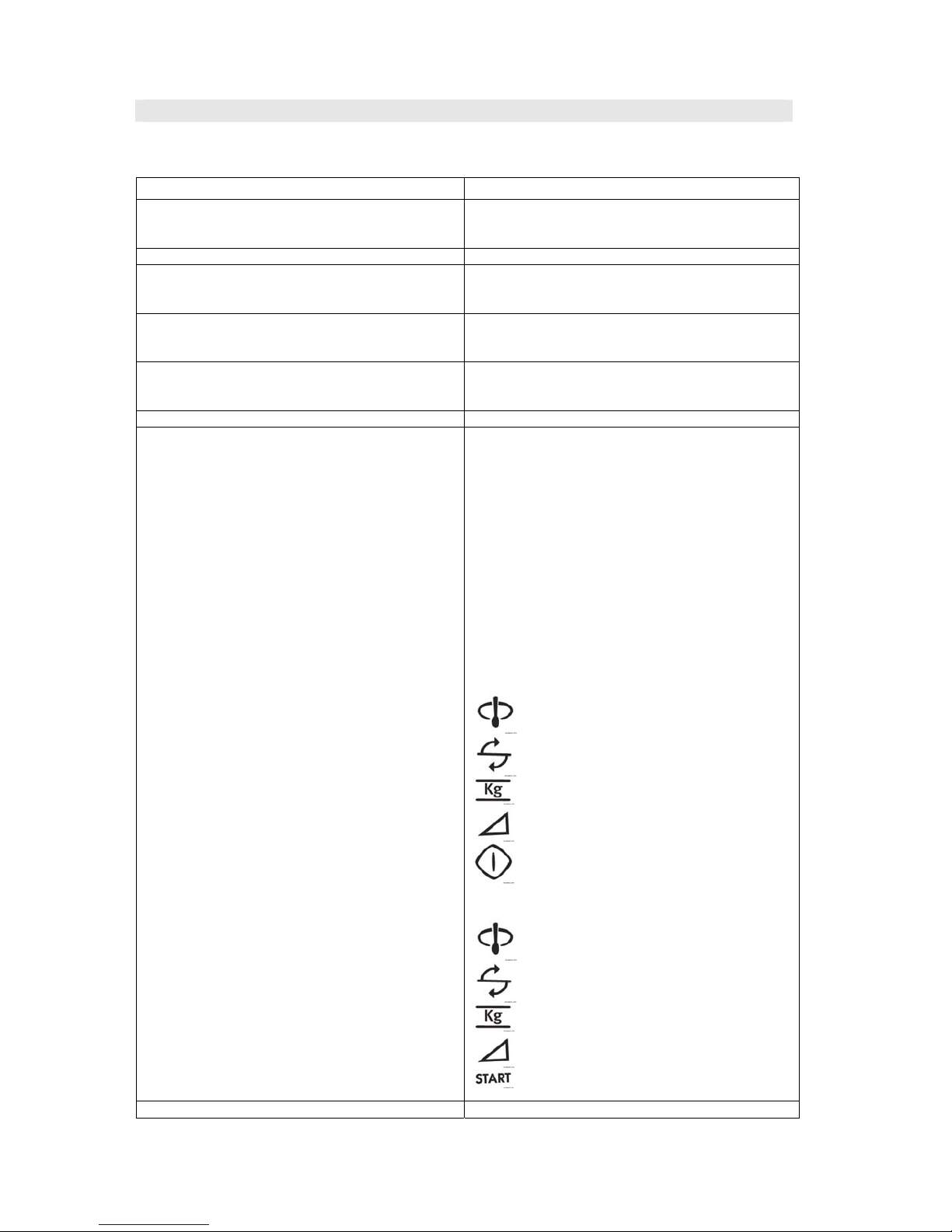
Stir
AUTOMATIC button
Turn over
MICROWAVE POWER
LEVEL button
Weight
STOP button
Microwave
power level
START/QUICK button
Cooking in
progress
TIMER/WEIGHT knob
Stir
AUTOMATIC button
Turn over
MICROWAVE POWER
LEVEL button
Weight
STOP button
Microwave
power level
START/ QUICK button
Control Complement
Cooking in
progress
TIMER/WEIGHT knob
Net weight Approx, 16kg
SOI 01.05 FV 7/33 599 36 78-06
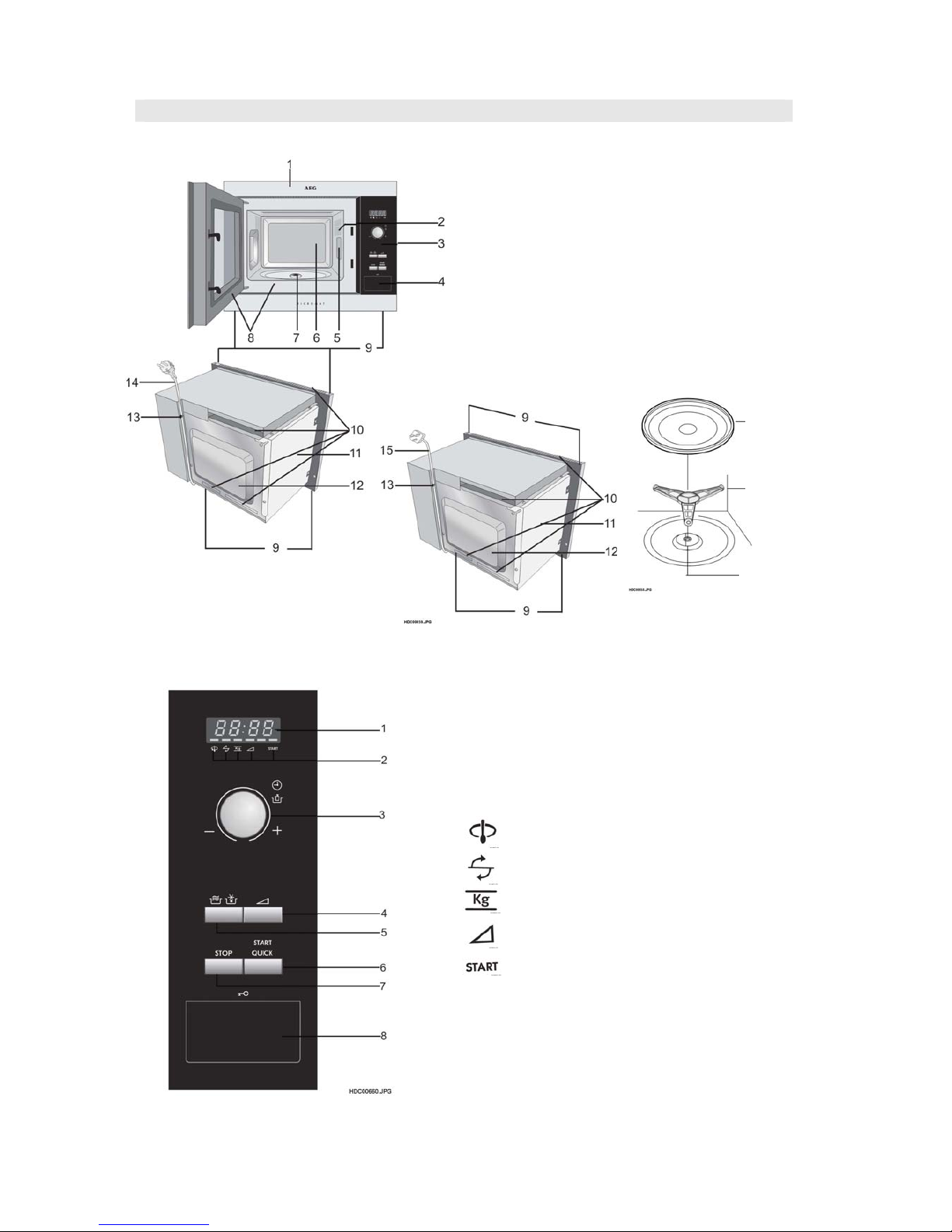
APPEARANCE VIEW
OVEN
1. Place the roller stay on the floor of
the oven cavity, engaging shaft into
turntable motor shaft.
2. Then place the turntable on roller
stay.
1 Digital Display
2 Indicators
The appropriate indicator will flash or light up,
just above each symbol according to the
instruction. When an indicator is flashing, press
the appropriate button (having the same symbol)
or carry out the necessary operation.
Stir
Turn oven
Weight
Microwave power level
Cooking in progress
3 TIMER/WEIGHT knob
4 MICROWAVE POWER LEVEL button
5 AUTOMATIC PROGRAMMES button
Press to select one of the 12 automatic programmes.
6 START/QUICK button
7 STOP button
8 DOOR OPEN button
Turntable
Roller stay
Seal packing
1 Front trim
2 Oven lamp
3 Control panel
4 Door opening button
5 Waveguide cover
6 Oven cavity
7 Seal packing
8 Door seals and sealing surfaces
9 Fixing points (4 points)
10 Ventilation openings
11 Outer cover
12 Rear cabinet
13 Power supply cord support clip
14 Power supply cord (EU)
15 Power supply cord (UK)
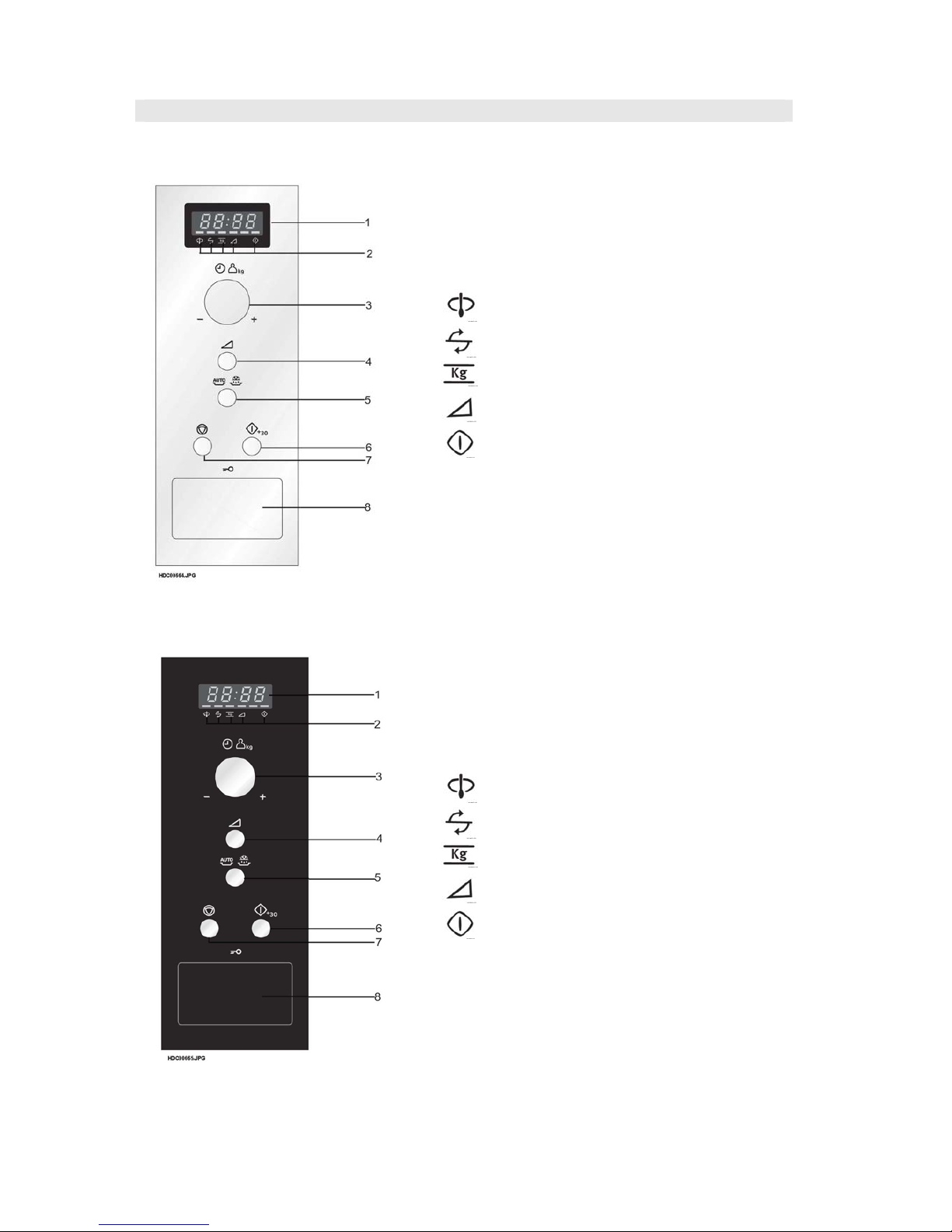
CONTROL PANEL
MC1751E/MC1761E/MOA4117
SOI 01.05 FV 8/33 599 36 78-06
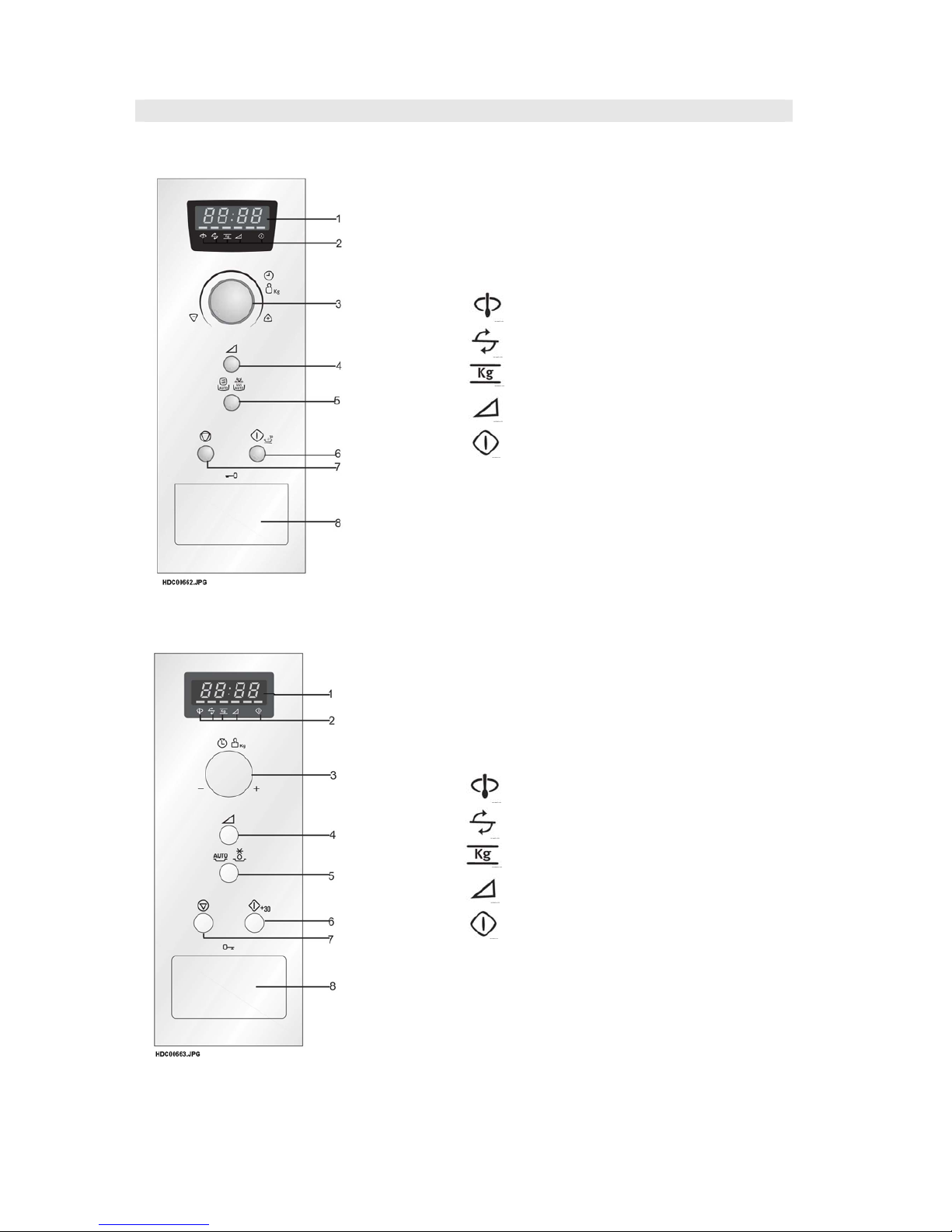
APPEARANCE VIEW
CONTROL PANEL
EMS1750X/EMS1760X
ZM175ST/ZM176ST
1 Digital Display
2 Indicators
The appropriate indicator will flash or light up,
just above each symbol according to the
instruction. When an indicator is flashing, press
the appropriate button (having the same symbol)
or carry out the necessary operation.
Stir
Turn oven
Weight
Microwave power level
Cooking in progress
3 TIMER/WEIGHT knob
4 MICROWAVE POWER LEVEL button
5 AUTOMATIC PROGRAMMES button
Press to select one of the 12 automatic programmes.
6 START/QUICK button
7 STOP button
8 DOOR OPEN button
SOI 01.05 FV 9/33 599 36 78-06
APPEARANCE VIEW
QN4025/QN4026
JMW1051/JMW1061
1 Digital Display
2 Indicators
The appropriate indicator will flash or light up,
just above each symbol according to the
instruction. When an indicator is flashing, press
the appropriate button (having the same symbol)
or carry out the necessary operation.
Stir
Turn oven
Weight
Microwave power level
Cooking in progress
3 TIMER/WEIGHT knob
4 MICROWAVE POWER LEVEL button
5 AUTOMATIC PROGRAMMES button
Press to select one of the 12 automatic programmes.
6 START/QUICK button
7 STOP button
8 DOOR OPEN button

SOI 01.05 FV 10/33 599 36 78-06
OPERATION SEQUENCE
MICROWAVE OFF CONDITION
Closing the door activates the door interlock switch (monitored latch switch).
IMPORTANT
When the oven door is closed, the monitor switch contacts COM - NC must be open.
When the microwave oven is plugged in a wall outlet (230V/ 230-240v 50Hz), the noise filter is energized.
Figure 0-1 on page 32
NOTE: When the oven door is opened, the oven lamp comes on at this time.
MICROWAVE COOKING CONDITION
HIGH COOKING
Enter a desired cooking time by rotating the time/weight knob
and start the oven by touching START pad.
Figure 0-2 on page 32
CONNECTED COMPONENTS RELAY
Oven lamp, Turntable motor RY1
Power transformer RY3
Fan motor RY4
1. The line voltage is supplied to the primary winding of the power transformer. The voltage is converted
to about 3.3 volts A.C. output on the filament winding and high voltage of approximately 2000 volts A.C.
on the secondary winding.
2. The filament winding voltage (3.3 volts) heats the magnetron filament and the high voltage (2000 volts)
is sent to the voltage doubling circuit, where it is doubled to negative voltage of approximately 4000 volts
D.C..
3. The 2450 MHz microwave energy produced in the magnetron generates a wave length of 12.24 cm.
This energy is channelled through the waveguide (transport channel) into the oven cavity, where the
food is placed to be cooked.
4. When the cooking time is up, a single tone is heard and the relays RY1 + RY3 + RY4 go back to their
home position. The circuits to the oven lamp, power transformer, fan motor and turntable motor are cut off.
5. When the door is opened during a cook cycle, the switches come to the following condition.
CONDITION
SWITCH
CONTACT
DURING
COOKING
DOOR OPEN
(NO COOKING)
Monitor switch COM-NC Open Closed
COM-NO Closed Open
Monitored latch switch COM-NO Closed Open
Stop switch COM-NO Closed Open
The circuits to the power transformer, fan motor and turntable motor are cut off when the monitored latch
switch is opened. The oven lamp remains on even if the oven door is opened after the cooking cycle has
been interrupted, because the relay RY1 stays closed. Shown in the display is the remaining time.
6. MONITOR SWITCH CIRCUIT
The monitor switch (SW2) is mechanically controlled by oven door, and monitors the operation of the
monitored latch switch (SW1)
6-1 When the oven door is opened during or after the cycle of a cooking program, the monitored latch
switch (SW1)and stop switch (SW3) must open their contacts(COM-NO) first. After that the contacts
(COM - NC) of the monitor switch (SW2) can be closed.
6-2 When the oven door is closed, the contacts (COM - NC) of the monitor switch (SW2) must be
opened first. The contacts (COM - NO) of the monitored latch switch (SW1) and stop switch (SW3)
are closed after.
6-3 When the oven door is opened and the contacts of the monitored latch switch (SW1) remain
closed, the fuse F1 will blow, because the monitor switch is closed and a short circuit is caused.
 Loading...