

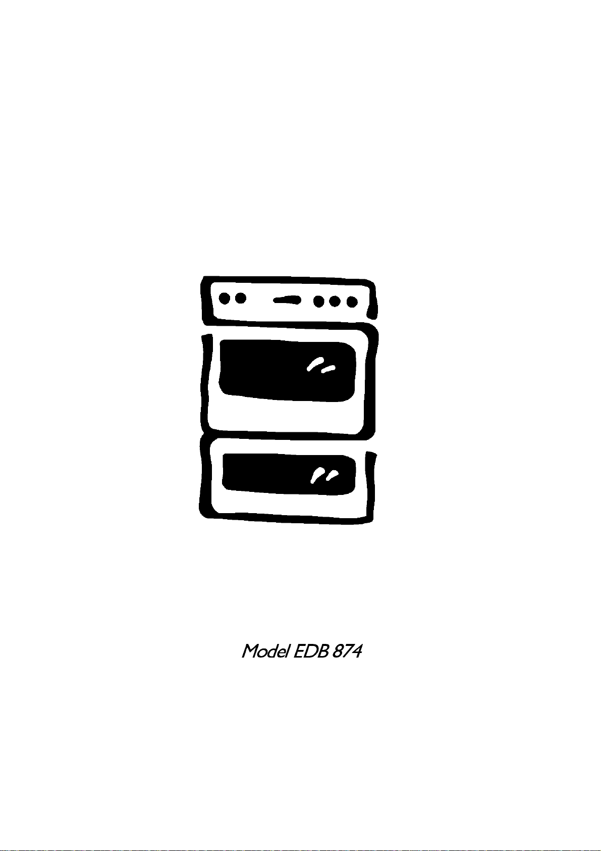
Model EDB 874
IMPORTANT SAFETY INFORMATION
These warnings are provided in the interests of your safety. Ensure that you understand them all before installing
or using the cooker. Your safety is of paramount importance. If you are unsure about any of the meanings of
these warnings contact the Customer Care Department. The address is on the back page of this book.
INSTALLATION
The cooker must be installed according to the
instructions supplied. The installation work must be
undertaken by a competent person as stated in the
Gas Safety (Installation & Use) regulations current
edition.
The installer should check that the cooker is suitable
for the gas supply by checking the data badge.
The cooker must be installed in an adequately
ventilated room.
NOTE: It is imperative that the appliance is left in the
base to protect both the appliance and the floor.
This cooker is heavy and care must be taken when
moving it. Do not try to move the cooker by pulling
the door handles.
Warning: Do Not attempt to lift this appliance by the
handles.
All packaging, both inside and outside the cooker
must be removed before the cooker is used.
It is dangerous to alter the specifications or modify
the cooker in any way.
After installation please dispose of the packaging with
due regard for safety and the environment. Your local
authority can arrange this.
CHILD SAFETY
Do not allow young children to play with any part of
the packaging.
This cooker is designed to be operated by adults.
Young children must not be allowed to tamper with
the controls or play near or with the cooker.
The cooker and accessible parts especially around
the grill area become hot when the cooker is in use.
Keep children away until it has cooled.
DURING USE
This cooker has been designed for domestic use to
cook edible foodstuffs only, and must not be used
for any other purpose.
Take great care when heating fats and oils as they
will ignite if they become too hot.
Never place plastic or any other material which may
melt in or on the oven.
Do not stand too close to the oven or grill while in
use as warm air will exhaust from the grill cavity and
the vents on the front frame of the cooker.
When lighting any burner check that it is lit before
leaving the cooker.
When turning off any burner do not leave the cooker
until the flame has gone out.
Do not leave the grill pan handle in position when
grilling and ensure oven gloves are used to remove
and replace the handle, as it will become hot.
Always use oven gloves to remove and place food
in the oven.
Ensure that all vents are left unobstructed to ensure
ventilation of the oven cavity.
Never line any part of the cooker with aluminium foil.
Stand clear when opening the drop down oven
doors. Support the doors using the handles until fully
open.
Never leave the cooker unattended when the
oven door is open.
Do not place sealed cans or aerosols inside the
oven. They may explode if they are heated.
Ensure that all control knobs are in the OFF position
when not in use.
Do not stand on the cooker or on the open oven
doors.
Do not hang towels, dishcloths or clothes from the
cooker or its handles. They are a safety hazard.
CLEANING AND MAINTENANCE
The cooker is heavy and care must be taken when
moving it.
For Hygiene and safety reasons this cooker
should be kept clean at all times. A build-up of
fats or other foodstuffs could result in a fire
especially in the grill pan.
This cooker should be kept clean at all times. A
build-up of fats or other foodstuffs could result in a
fire, especially in the grill pan.
Do not leave cookware containing foodstuffs, e.g. fat
or oil in the cooker in case it is inadvertently
switched on.
Always allow the cooling fan to cool the cooker
down before switching off at the wall prior to carrying
out any cleaning / maintenance work.
Only clean this cooker in accordance with the
instructions given in this book.
SERVICE
Repairs should not be carried out by inexperienced
persons as this may cause injury or serious
malfunction. This cooker should be serviced by an
authorised Service Engineer and only genuine
approved spare parts should be used. Details of
servicing and repair arrangements are supplied on
page 35
of this book.
AT THE END OF THE COOKERS LIFE
When the time comes to dispose of your cooker
please contact your local Council Authority. They
can arrange to dispose of the cooker in a safe and
controlled manner.
The number will be in the telephone book.
Please read this
instruction book carefully
before use and retain
for future reference.
2
CONTENTS
FOR THE USER
Important Safety Information 2
Description of the cooker 5
Getting to Know Your Oven 6
The Cooling Fan for the Controls 7
Location 7
Before Using The Cooker 8
Rating Plate 8
Connecting to the Electricity Supply 8
When First Switching On 8
Condensation and Steam 9
Cookware 9
The Trivet 9
Grill and Oven Furniture 10
The Electronic Timer 11
Care and Cleaning 29
Cleaning Materials 29
Cleaning the Outside of the Cooker 29
Cleaning the Outer and Inner Door
Glass Panels 30
Cleaning Inside the Ovens 31
To Remove the Wirework Runners 32
Cleaning the Shelves, Wirework Runners
and Oven Furniture 32
Care of Stayclean Surfaces 32
The Oven Cleaning Cycle 33
Things to Note 33
Hints and Tips 33
The Grill 15
Uses of the Grill 15
How To Light the Grill 15
Things To Note 15
The Grill Shelf 16
The Grill Pan and Handle 16
Hints and Tips 17
Grilling Chart 18
The Top Oven 19
Uses of the Top Oven 19
Preheating 19
How To Light the Top Oven 19
Things To Note 19
To Fit the Top Oven Shelf 20
Hints and Tips 20
Top Oven Cooking Chart 21
The Main Oven 22
Uses of the Main Oven 22
Preheating 22
How To Light the Main Oven 22
Things to Note 22
To Fit the Main Oven Shelves 23
Hints and Tips 23
Main Oven Cooking Chart 25
Replacing an Oven Light Bulb 34
If Something Doesn't Work 35
Service and Spare Parts 37
Guarantee Conditions 38
Customer Service Centres 39
Please read the whole instruction book before
using the cooker. To help you the following
symbols will be found in the text.
Safety Instructions
Step by Step Instructions
Hints and Tips
Slowcook Feature 26
Uses of Slowcook 26
How To Use Slowcook 26
Things to Note 26
Hints and Tips 26
3

FOR THE INSTALLER
Technical Details 4 1
Things You Need to Know 42
Warnings 42
Things to Note 42
Getting Things Ready 43
Preparing Cabinet for Fitting Oven 43
Flexible Pipe Installation 43
Making the Electrical Connections 45
Connection to Electricity Supply 45
Checking Electrical Connections 46
Pressure Testing 47
.
4
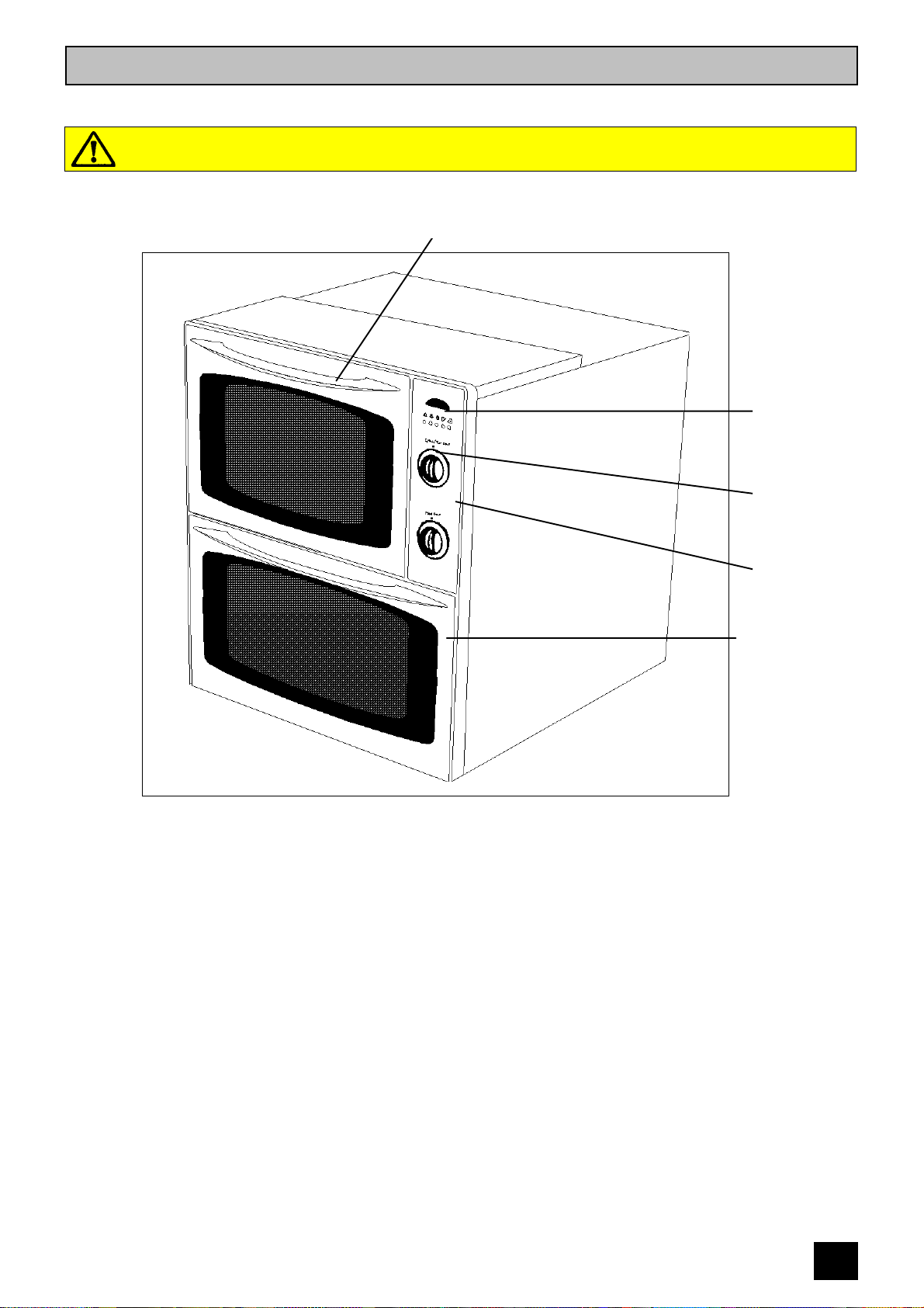
DESCRIPTION OF THE COOKER
Built in gas double oven
WARNING: THIS COOKER MUST BE EARTHED AND PROTECTED BY A 3 AMP FUSE
Top Oven / Grill
Electronic
Timer
Control
Knob
Control
Panel
Main Oven
Your built in cooker comprises of a gas oven and grill in the top compartment. The top oven is
convenient and economical for mid-week use because of its size.
The main oven is the larger of the two ovens. It is particularly suitable for cooking larger quantities of
food. In addition, the Slowcook feature allows you to cook a range of foods over a long period of time at
a low temperature.
The Main oven can be automatically controlled by the electronic timer.
5
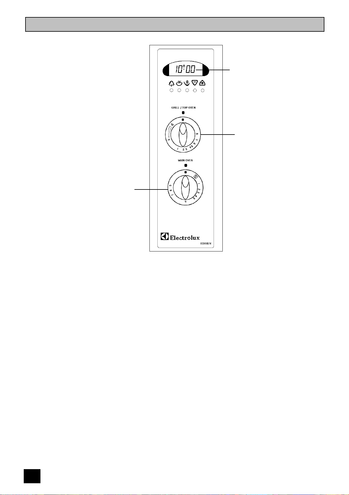
GETTING TO KNOW YOUR OVEN
The Control Panel
Main Oven Control
Electronic Timer
Grill / Top Oven Control
6

THE COOLING FAN FOR THE CONTROLS
Your cooker has a cooling fan fitted behind the
controls to prevent them from overheating.
The cooling fan will come on immediately when
the top oven or grill is switched on and after a
short time when the main oven is in use.
The cooling fan may run on after the ovens or
grill are turned off for a period of time to cool
the cooker down. It may continue to switch on
and off until the cooker is cool.
Always allow the cooling fan to cool
the cooker down before switching off
at the wall prior to carrying out any
cleaning or maintenance work.
NOTE
The action of the cooling fan will depend on
how long the ovens or grill have been used and
at what temperature. It may not run on where
the grill or oven has only been used for a short
time.
Do not stand too close to the grill or
oven when in use as warm air will
exhaust from the grill cavity and oven
vents.
LOCATION
All gas ovens require adequate
ventilation. The room the oven is fitted in
must have a good air supply that meets
the standard BS 5440 Part 2 (current
edition). Your installer will tell you if you
are not sure.
The oven may be placed in a kitchen,
kitchen/diner or bedsit but not in a
bathroom or shower room. It should not
be installed in a bedsit smaller than 20m
L.P.G. cookers MUST NOT be installed
below ground level, i.e. in a basement, or
aboard any boat, yacht or other vessel.
3
.
The use of a gas cooking appliance results in
the production of heat and moisture in the room
in which it is installed. Ensure that the kitchen is
well ventilated: keep natural ventilation holes
open or install a mechanical ventilation device (
mechanical extractor hood).
Prolonged intensive use of the appliance may
call for additional ventilation, for example
opening of a window, or more effective
ventilation, for example increasing the level of
mechanical ventilation where present.
7
BEFORE USING THE COOKER
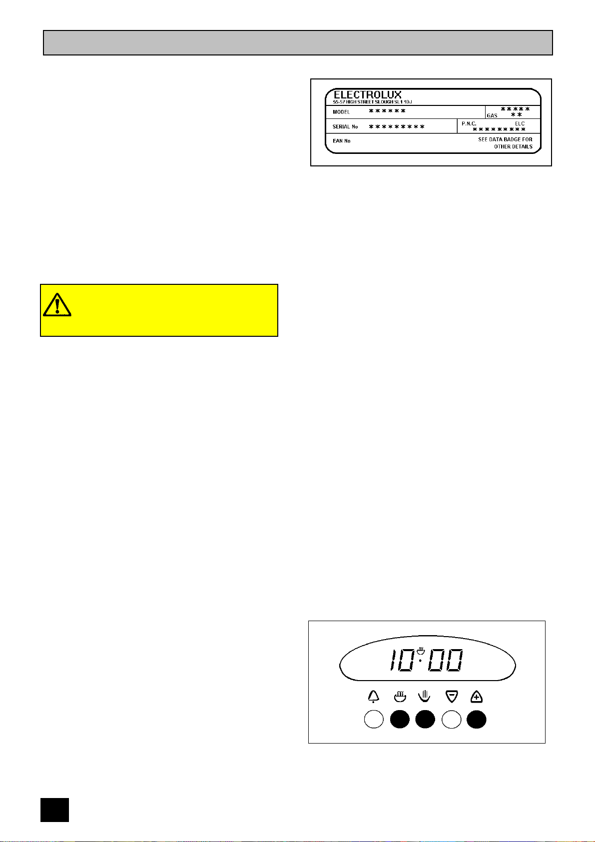
NAME PLATE
Record the model, product and serial numbers
of your cooker on the back page of this
instruction book for future reference. You can
find these numbers on the name plate on the
front frame of the cooker upon opening the top
oven door.
The cooker must be protected by a suitably
rated fuse or circuit breaker. The rating of the
cooker is given on the rating plate.
Do not remove the rating plate from the
cooker as this may invalidate the guarantee.
CONNECTING TO THE
ELECTRICITY SUPPLY
This cooker must be earthed and
protected by a 3 amp fuse.
The plug supplied with the oven can be fitted
directly to a suitable three pin earthed socket.
If you have to change the fuse replace it with a
3 amp fuse which has been ASTA approved to
BS 1362.
Do not use the plug until you have put the fuse
cover back on. If you cut the plug off dispose of
it safely as it will be a shock hazard if it is
inserted into a 13 amp socket elsewhere in the
house.
If the ignition system doesn't work there may be
a fault with the electrical supply. First, check the
socket by trying out another piece of electrical
equipment in it, if that works correctly renew the
fuse in the plug.
If the fuse keeps failing there is a fault in the
oven which must be put right. Do not use a fuse
with a rating higher than 3 amps. Do not carry
out other electrical work. Unplug the oven and
tell your installer.
WHEN FIRST SWITCHING ON
The timer must be set to manual operation
before the main oven can be operated. This
must be done whenever the cooker is switched
off at the wall or when there has been a power
failure. For instructions on how to set the timer
see page 11.
The Top Oven and the Grill are not controlled
by the electronic timer.
8
PREPARING TO USE YOUR
COOKER
Wipe the base of the ovens with a soft cloth
and some hot soapy water and wash the grill
and oven furniture before use. The grill and
ovens should be heated without food to burn off
any residue from the grill and oven surfaces.
To do this run the oven at Gas Mark 7 for
approximately 10 - 15 minutes. The procedure
should be repeated with the grill for
approximately 5 - 10 minutes.
During this period an unpleasant odour may be
emitted, it is therefore advisable to open a
window for ventilation.
CONDENSATION AND STEAM
When food is heated it produces steam in the
same way as a boiling kettle does. The ovens
are vented to allow some of this steam to
escape. However, always stand back from the
cooker when opening the oven doors to allow
any build up of steam or heat to release. If the
steam comes into contact with a cool surface
on the outside of the cooker, e.g. a trim, it will
condense and produce water droplets. This is
quite normal and is not caused by a fault on the
cooker.
To prevent discolouration occurring, regularly
wipe away condensation and any soilage from
the cooker surfaces.
COOKWARE
Baking trays, dishes etc., should not be placed
over the oven burner. This will damage the
oven as well as the ovenware.
Do not use baking trays larger than 30cm x
30cm (12" x 12") as they will restrict the
circulation of heat and may affect performance.
Advice on the effect of different materials and
finishes of bakeware is given in 'Hints and Tips'
in the appropriate oven section.
If using a baking tray larger than 30cm x 25cm
(12" x 9") in the top oven you may need to turn
it round during cooking.
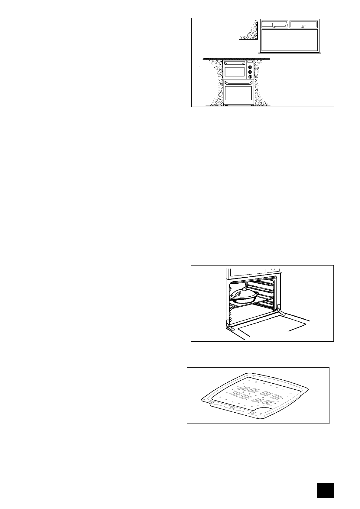
THE TRIVET
When roasting we recommend that you use the
trivet in the meat tin. Fat and meat juices will
drain into the meat tin below and can be used
to make gravy. The trivet also prevents
splashes of fat from soiling the oven interior.
Note. The meat tin should not be placed on a
heated hotplate as this may cause the enamel
to crack.
9
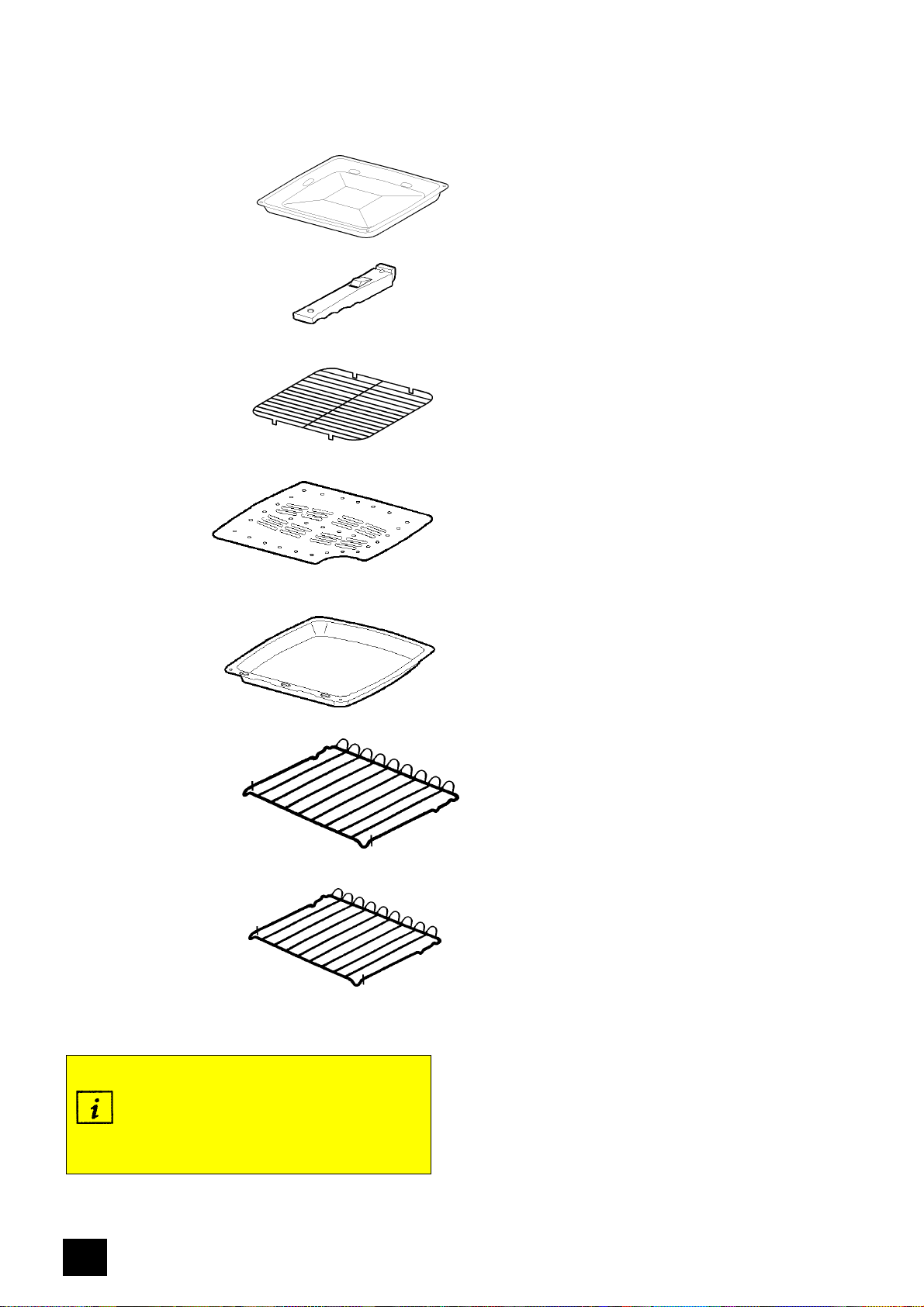
GRILL AND OVEN FURNITURE
The following items of oven furniture have been
supplied with the cooker.
1 grill pan
1 grill pan handle
1 grill pan grid
1 trivet
1 meat tin
2 shelves for main
oven cooking
1 shelf for grilling and
top oven cooking
10
Scuffing of the Stayclean sides and
back panel by the oven furniture pack
may occur during transit.
These marks will disappear after the
oven has been used for the first time.
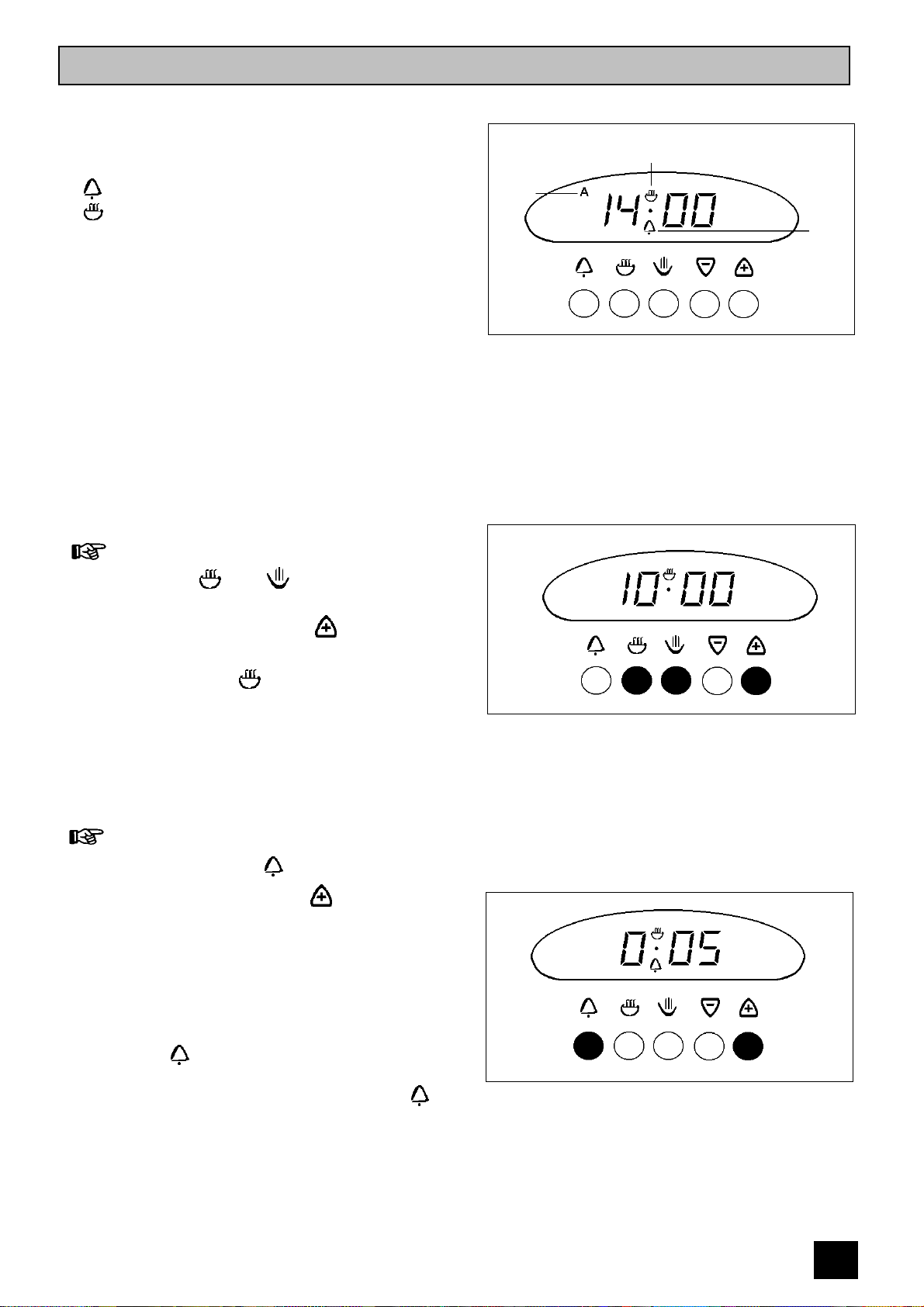
THE ELECTRONIC TIMER
The electronic timer can indicate the time of
day, operate as a minute minder and
automatically time the main oven.
A - Auto Symbol ( automatic cooking)
- Bell Symbol ( minute minder)
- Cookpot Symbol ( manual cooking)
Please note that this is a 24 hour clock, for
example 2pm is shown as 14.00.
If the oven is switched off on the wall or there is
loss of power the clock will stop and you will not
be able to use the cooker. When you first switch
the electricity supply on, the timer display will
flash.
Auto
Cookpot Symbol
Symbol
Bell
Symbol
TO SET THE TIME OF DAY
1.Press buttons and together.
Release the buttons.
2. Within 5 seconds press the button until
the time of day shows in the display.
The cookpot symbol ( ) will be showing.
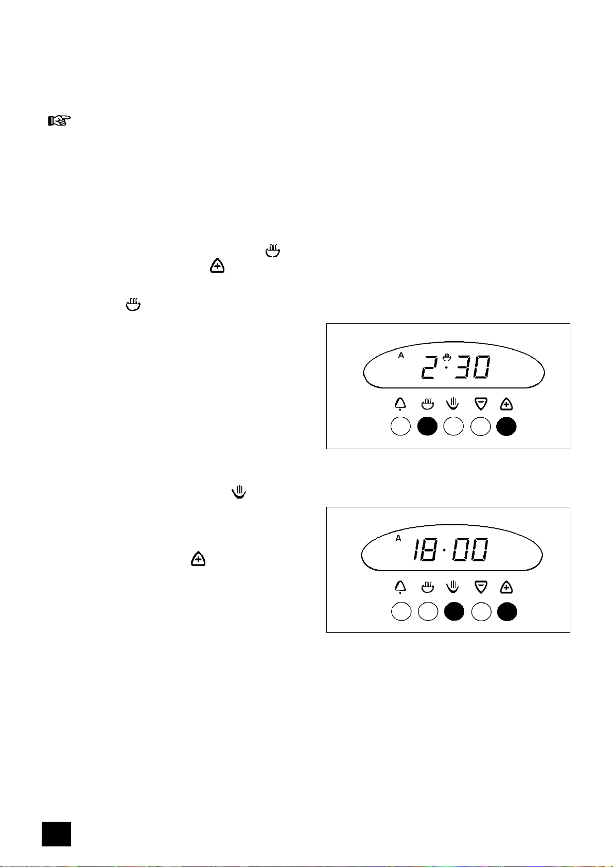
THE MINUTE MINDER
1.Press and release the button.
2. Within 5 seconds press the button until
the display shows the time you want.
Our diagram shows the timer set to 5 minutes.
After a few seconds the time of day will show in
the display.
When you are using the minute minder you can
check the number of minutes remaining by
pressing the button.
At the end of the timed period an alarm will
sound. Switch off the alarm by pressing the
button.
After a few seconds the time of day shows in
the display.
11
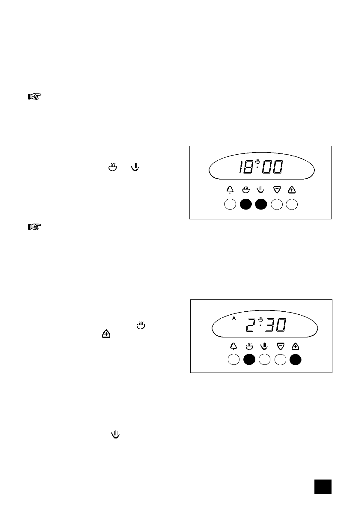
AUTOMATIC TIMER CONTROL
The automatic timer can be used with the main
oven only.
TO SWITCH THE MAIN OVEN
ON AND OFF AUTOMATICALLY
1. Ensure the clock is showing the correct time
of day.
2.Place food in the main oven.
3. Set the length of time you want the food to
cook for by pressing and releasing the
button and then pressing the button until
the correct cooking time is displayed.
This must be completed within 5 seconds of
pressing the button.
The maximum cooking time is 23 hours 59
minutes.
The Cookpot and Auto symbols will show in the
display. Our diagram shows the cooking time
set for 2 hours 30 minutes.
After a few seconds the time of day shows in
the display.
4.To set the time you want the food to be
cooked by, press and release the button.
This will show you the earliest possible stop
time.
If this is different to the time you want the food
to be cooked by, press the button within 5
seconds until the correct stop time shows in the
display. Our diagram shows the food is to be
cooked by 18.00 (6pm).
After a few seconds the time of day shows in
the display and the Cookpot symbol goes out.
The 'Stop' time must not be more than 23 hours
59 minutes from the time of day. For example, if
the time of day is 09.00 hours (9.00am) the
latest 'Stop' time will be 08.59 (8.59am) the next
day.
12
5. Turn the oven control to mark 9 then to the
required setting.
The clock will work out what time the oven will
switch itself on and will switch the oven off at
the end. An audible signal will sound when
cooking is complete. To cancel the alarm, see
below.
RETURNING THE COOKER TO
MANUAL OR TO CANCEL AN
AUTOMATIC PROGRAMME
Once automatic cooking is complete an alarm
will sound and the Auto symbol will flash to
remind you that the oven needs to be set for
manual operation.
1.To do this press buttons and together.
After a few seconds the timer will show the
time of day. The cookpot will show in the
display and the oven will switch on again.
2.Turn off the oven control.
TO SET THE TIMER TO
SWITCH OFF ONLY
This is useful if you want to begin cooking
immediately but have the Main oven switch off
whilst you are out.
1. Ensure the clock is showing the correct time
of day.
2.Place food in the oven.
3. Set the length of time you want the food to
cook for. Press and release the button
and then press the button within 5
seconds until the correct cook time is
showing.
Our diagram shows the timer set for 2 hours 30
minutes.
After a few seconds the time of day shows in
the display.
4.Turn the control to mark 9 then to the
required setting.
If you want to check the time the oven will
switch off simply press the button and the
'Stop' time will be displayed.
13

At the end of the cooktime the oven will switch
off, the alarm will sound and the auto symbol
will flash.
5.To cancel and return to manual operation
press buttons and together.
6.Turn off the oven temperature control.
14

THE GRILL
WARNING - Accessible parts become
hot when the grill is in use. Keep
children away.
USES OF THE GRILL
The grill is situated in the Top oven
compartment.
The grill gives variable heat settings. Use the
high setting for foods that cook quickly such as
toast and the lower setting to cook thicker foods
such as chicken after it has been browned on
the high setting.
HOW TO LIGHT THE GRILL
1.Open the Grill / Top Oven door.
2. Push in the grill / top oven control and turn it
clockwise to the highest setting. This is
shown by a large flame symbol.
GRILL / TOP OVEN
3.Adjust the setting as required.
4.Place grill pan with food under the grill.
The grill door must be left open when
grilling.
Check that the grill burner is lit before
you leave the cooker.
Never cover the grill pan or grid with
foil as this can lead to grill fires.
TO TURN OFF THE GRILL
BURNER
1.Push in the control knob and turn it to the Off
position. This is shown by a large dot.
THINGS TO NOTE
The cooling fan for the controls will operate
as soon as the grill control is turned. For
more information on the operation of the
cooling fan turn to page 7.
The oven light will illuminate.
If the oven door is closed whilst the grill
burner is lit, it will go out. The burner will
automatically re-light when the door is
opened.
Always light the burner before placing food
under the grill.
GRILL / TOP OVEN
15
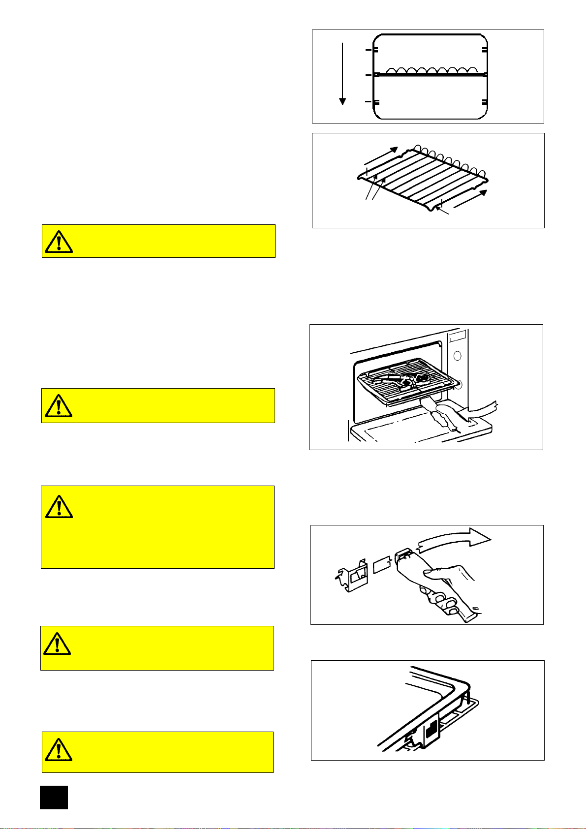
THE GRILL SHELF
The grill shelf can be used in one of three
positions. Shelf positions are counted from the
top downwards.
The shelf should be fitted with the straight rods
uppermost on the frame and the forms towards
the back of the oven. If not fitted correctly the
anti-tilt and safety stop mechanism will be
affected.
When using the grill pan in positions 2 and 3
the shelf must be withdrawn before the pan can
be located or removed.
Ensure the pan is properly located.
THE GRILL PAN AND HANDLE
The grill pan has a removable handle.
To insert the handle, press the button on the
handle with the thumb and pivot the handle
slightly upwards inserting the lip into widest part
of the bracket. Move the handle towards the
left, lower into position and release the button.
1
2
3
Back of the oven
Straight Rods
Frame
Ensure the handle is positively located.
To remove the handle, press the button on the
handle with the thumb and pivot the handle
slightly upwards and towards the right to
remove from the bracket.
Protect your hands when removing the
grill pan handle.
Always remove the grill pan handle
during grilling.
To correctly locate the grill pan on the shelf,
ensure that the cut out on the underside of the
handle bracket locates over the front bar of the
shelf.
The Grill Pan must not be located in
the shelf runners
To check the progress of the food being grilled,
the grill pan should be withdrawn on the shelf to
attend to food during cooking.
Ensure that the grill pan is supported
when it is withdrawn.
16

HINTS AND TIPS
Most foods should be placed on the grilling
grid in the grill pan. This allows maximum
circulation of air by raising the food out of fats
and juices.
The grilling grid is reversible. Adjust the grid
height and grill pan runner position to allow
for different thicknesses of food. Position the
food close to the burner for faster cooking
and further away for more gentle cooking.
Food should be thoroughly dried before
grilling to minimise splashing. Brush lean
meats and fish lightly with a little oil or melted
butter to keep them moist during cooking.
The food should be turned over during
cooking as required. Do not use the grill to
keep food warm as it will continue to cook the
food.
The grill door must be left open when grilling.
For convenience the grill door can be left
ajar.
You may wish to preheat the grill on full
setting for a few minutes before sealing
steaks or browning food.
The grill compartment can be used to warm
plates when the main oven is on.
Do not place plates to warm under the grill
when it is lit as this may damage the plates.
17

Place food towards the centre of the grilling
grid. If food is outside this area it may require
rotating during cooking. Food such as
tomatoes and mushrooms requiring gentle
heat should be placed towards the edge of
the grid.
Place foods such as Shepherds pie and
cauliflower cheese on the grill shelf to brown.
GRILLING CHART
The chart below gives recommended cooking
times and shelf positions. Remember that these
are a guide and should be adjusted to suit
personal taste.
Note
Shelf positions are counted from the top
downwards.
FOOD GRILL TIME
(Min)
Bacon Rashers
Beefburgers
Chicken Joints
Chops - Lamb
- Pork
Fish - Whole Trout / Mackerel
Fillets - Plaice / Cod
Kebabs
Kidneys - Lamb
Pig
Liver - Lamb / Pig
Sausages
2 - 3 each side
6 - 10 each side
15 - 20 each side
7 - 10 each side
10 - 15 each side
8 - 12 each side
4 - 6 each side
10 - 15 each side
4 - 6 each side
8 - 10 each side
5 - 10 each side
10 - 15 turn as
required
SHELF GRID
POSITION
1
1
2
1
1
1
1
1
1
1
1
1
High
Low
High
Low
Low
Low
Low
Low
Low
Low
Low
Low
Steaks - Rare
Medium
Well Done
Browning e.g. au gratin,
lasagne, shepherd's pie
18
3 - 6 each side
6 - 8 each side
7 - 10 each side
3 - 5 mins
1
1
1
2
High
High
High
-

THE TOP OVEN
USES OF THE TOP OVEN
The top oven is the smaller of the two ovens.
It is convenient for smaller quantities or
convenience foods. It is important to refer to
the top oven cooking chart as a guide to shelf
positions and gas mark settings as these may
differ from previous cookers you may have
used.
PREHEATING
It is not necessary to preheat the oven for
casseroles.
For recipes needing high temperatures such as
bread, pastries, scones, soufflés etc. best
results are achieved if the oven is preheated for
20 minutes.
When cooking or reheating frozen or chilled
food read the instructions on the packaging.
GRILL / TOP OVEN
HOW TO LIGHT THE TOP
OVEN
1.Open the grill / top oven door.
2.Push in and turn the top oven / grill control to
the left to Gas mark 8.
When the burner has lit there will only be
small flames at first.
3. Adjust the control to the required Gas mark
setting.
4.Wait until the burner has a large flame.
5.Close the oven door.
THINGS TO NOTE
The cooling fan for the controls will operate
as soon as the top oven / grill control is
turned. See page 7 for more information on
the operation of the cooling fan.
The oven light will illuminate.
The top oven cannot be controlled by the
automatic timer.
Do not place cookware over the oven
burner. This will damage the oven and
ovenware.
GRILL / TOP OVEN
GRILL / TOP OVEN
TO TURN OFF THE TOP OVEN
1.Push in and turn the top oven / grill control to
the Off position. This is shown by a large dot.
19

TO FIT THE TOP OVEN SHELF
There are 3 shelf positions in the top oven.
Shelf positions are counted from the top
downwards.
1
2
3
The shelf should be fitted with the straight rods
uppermost on the frame and the forms towards
the back of the oven.
If not fitted correctly the anti-tilt and safety stop
mechanism will be affected
HINTS AND TIPS
There are zones of heat within the oven. The
temperature in the middle is the gas mark you
have chosen. The top of the oven is slightly
hotter and the lower shelf slightly cooler.
The base of the oven can be used to warm
plates.
You can only cook on one shelf when using
the top oven.
There should always be at least 2.5cm (1")
between the top of the food and the grill
burner. This gives best cooking results and
allows room for rise in yeast mixtures,
Yorkshire puddings etc. When cooking cakes,
pastry, scones bread etc., place the tins or
baking trays centrally on the shelf.
.
Back of the oven
Straight Rods
Frame
1
2
3
Leave a gap of 13mm (½") between all
dishes and the oven sides so the heat can
circulate properly.
Do not push dishes too far back as it will burn
if it overhangs the burner flames.
If you use a baking tray larger than the
recommended size of 12" x 9", (30cm x
25cm), you may need to turn it around during
cooking.
Where a larger quantity of food is to be
cooked we recommend you use the main
oven.
The material and finish of the baking tray and
dishes will affect the degree of base browning
of the food. Enamelware, dark, heavy or
non-stick utensils increase base browning.
Shiny aluminium or polished steel trays
reflect the heat away and give less base
browning.
20

For economy leave the door open for the
shortest possible time, particularly when
placing food into a pre-heated oven.
TOP OVEN COOKING CHART
The Gas mark settings are intended as a guide only. It may be necessary to increase or decrease the
settings to suit individual preferences and requirements.
Note: Shelf positions are counted from the top downwards.
FOOD SHELF POSITION GAS MARK SETTING
Viennese Biscuits
Bread
Bread Rolls / Buns
Cakes: Small & Queen
Sponges
Victoria Sandwich
Madeira
Rich Fruit
Christmas
Gingerbread
Meringues
Flapjack
Shortbread
Baked Custard
Casseroles : Beef / Lamb
Chicken
Convenience Foods
Fish
Fish Pie - potato topped
Fruit Pies, Crumbles
Milk Puddings
Pasta / Lasagne etc.
Pastry : Choux - Eclairs/profiteroles
Flaky / Puff pies
Shortcrust Mince pies
Meat pies
Quiche, Tarts, Flans
Roast Meat / Poultry
Scones
Shepherds Pie
Soufflés
Vegetables : Baked Jacket Potatoes
Roast Potatoes
Yorkshire Puddings - large
- individual
3
2
2
2
2
2
2
2
3
3
3
2
2
2
3
3
2
2
2
2
2
2
2
2
2
2
2
3
2
2
2
2
2
2
2
According to Manufacturers Instructions
7
7
7
5
4
4
4
2
2
2
1
5
2
3
3
4
5
7
6
2
6
4
7
5
6
6
5
7
7
5
5
6
7
7
21

THE MAIN OVEN
USES OF THE MAIN OVEN
The main oven is particularly suitable for
cooking larger quantities of food. The main
oven also includes a Slowcook feature. It is
important to refer to the main oven cooking
chart as a guide to shelf positions and gas mark
settings as these may differ from previous
cookers you may have used.
PREHEATING
It is not necessary to preheat the oven for
casseroles.
For recipes needing high temperatures such as
bread, pastries, scones, soufflés etc. best
results are achieved if the oven is preheated for
20 minutes.
When cooking or reheating frozen or chilled
food read the instructions on the packaging.
HOW TO LIGHT THE MAIN
OVEN
1.Open the oven door.
2. Push in the main oven control and turn it to
gas mark 9.
3.Adjust the control to the required gas mark
setting.
4.Wait until the burner has a large flame.
5.Close the oven door.
THINGS TO NOTE
The oven light will come on when the oven
control is turned.
The cooling fan for the controls may operate
after a time. See page 7 for further details on
the operation of the cooling fan.
If an automatic programme has been set, the
oven light does not come on until the cook
time begins.
Do not place cookware over the oven
burner. This will damage the oven and
ovenware.
MAIN OVEN
MAIN OVEN
MAIN OVEN
TO TURN OFF THE MAIN
OVEN
1.Push in the control knob and turn it to the Off
position. This is shown by a large dot.
22

TO FIT THE MAIN OVEN SHELVES
There are 14 shelf positions in the main oven.
Shelf positions are counted from the top
downwards.
The shelves should be fitted with the straight
rods uppermost on the frame and the forms
towards the back of the oven. If not fitted
correctly the anti-tilt and safety stop mechanism
will be affected.
HINTS AND TIPS
There are zones of heat within the oven. The
temperature in the middle is the gas mark you
have chosen. The top of the oven is slightly
hotter and the lower shelf slightly cooler.
The base of the oven can be used to warm
plates.
1
14
Straight Rods
Back of the oven
Frame
Use the heat zones when cooking foods
requiring different temperatures all at the
same time.
When cooking more than one tray of similar
items, for example cakes or biscuits, swap
the trays round during cooking. Alternatively
remove the top tray when the food is cooked
and move the lower tray to the higher shelf to
finish cooking.
It is recommended that when baking larger
quantities, the shelf positions should be
evenly spaced to suit the load being cooked.
A slight increase in cooking time may be
necessary.
The material and finish of the baking tray and
dishes will affect the degree of base browning
of the food. Enamelware, dark, heavy or
non-stick utensils increase base browning.
Shiny aluminium or polished steel trays
reflect the heat away and give less base
browning.
23

For economy leave the door open for the
shortest possible time, particularly when
placing food into a pre-heated oven.
When roasting we recommend that you use
the trivet in the meat tin. Fat and meat juices
will drain into the meat tin below and can be
used to make gravy. The trivet also prevents
splashes of fat from soiling the oven interior.
Note. The meat tin should not be placed on a
heated hotplate as this may cause the enamel
to crack.
ROASTING
For best results we recommend open roasting
using minimal fat or oil to prevent splashing.
It is not necessary to cover meat or poultry or
wrap food in foil when roasting as this restricts
the circulation of heat and will lead to extended
cooktimes.
If you are using a roasting bag or cover chicken
breast with foil, be prepared to allow an extra
10 - 15 minutes for each 1/2kg (1lb).
When cooking large items such as turkeys, the
use of foil may be required to prevent the
breast becoming dry before the rest of the bird
is fully cooked.
24

MAIN OVEN COOKING CHART
The Gas mark settings are intended as a guide only. It may be necessary to increase or decrease the
settings to suit individual preferences and requirements.
Note: Shelf positions are counted from the top of the oven downwards.
FOOD SHELF POSITION GAS MARK
SETTING
Viennese Biscuits
Bread
Bread Rolls / Buns
Cakes: Small & Queen
Sponges
Victoria Sandwich
Madeira
Rich Fruit
Christmas
Gingerbread
Meringues
Flapjack
Shortbread
Baked Custard
Casseroles : Beef / Lamb
Chicken
Convenience Foods
Fish
Fish Pie - potato topped
Fruit Pies
Crumbles
Milk Puddings
Pasta / Lasagne etc.
Pastry : Choux - Eclairs/profiteroles
Flaky / Puff pies
Shortcrust Mince pies
Meat pies
Quiche, Tarts, Flans
Roast Meat / Poultry
Turkey
Scones
Shepherds Pie
Soufflés
Vegetables : Baked Jacket Potatoes
Roast Potatoes
Yorkshire Puddings - large
- individual
7
10
10
5 & 11
5 & 11
5 & 11
7
9
10
8
14
7
7
10
10
10
7
7
8
4 & 10
6
10
7
5
7
7
4
5 & 11
7
9
14
5 & 11
8
7
7
10
5
5
7
7
7
5
5
4
4
2
2
2
1 - 2
5
2
3
3
4
According to
Manufacturers Instructions
5
7
6
5
2
5
4
7
6
5
6
5
5
5
7
7
5
5
6
7
7
25

SLOWCOOK FEATURE
USES OF SLOWCOOK
Slowcooking in the main oven allows most
foods to be cooked at a low temperature over a
number of hours. A variety of foods, particularly
cheaper cuts of meat can be cooked in this way
making them tender, tasty and succulent.
This feature is most convenient when used in
conjunction with the automatic timer as there is
no need to be present at the start of cooking.
HOW TO USE SLOWCOOK
1.Open the main oven door.
2. Push in the main oven control and turn it to
gas mark 9. When the burner has lit there will
only be small flames at first.
3.Turn the control to the Slowcook setting.
4.Wait until the burner has a large flame.
5.Close the oven door.
THINGS TO NOTE
The oven light will come on when the oven
control is turned.
The cooling fan for the controls may operate
after a time. See page 7 for further details on
the operation of the cooling fan.
If an automatic programme has been set, the
oven light does not come on until the cook
time begins.
S
S
MAIN OVEN
MAIN OVEN
Do not place cookware over the oven
burner. This will damage the oven and
ovenware.
HINTS AND TIPS
Always cover food with a close fitting lid or tin
foil.
Do not re-heat food using the slow cook
function.
Slow cooked food should be eaten as soon
as possible after cooking. It is not advisable
to allow food to cool down slowly.
It is recommended that vegetable dishes,
sponge and suet puddings are prepared just
prior to cooking.
A complete meal can be cooked using slow
cook function.
Most foods should be cooked on the middle
shelf. Use shelf position 9 for large joints and
stews. Ensure dishes are evenly spaced to
allow for maximum circulation around food.
Thicken casseroles by tossing meat in flour
first or by blending flour with water and
adding at the end.
Pastries, breads and biscuits are not suitable
for slow cooking.
Adjust seasoning at the end of the cook time.
Thaw frozen foods thoroughly before
cooking.
26

MEAT, FISH AND POULTRY
Prime cuts of meat for roasting are better not
slow cooked as flavours are retained to their
fullest when roasting.
Do not Slowcook joints of meat over 6lb
(2.7kg) in weight.
Only Slowcook joints of pork if you can make
sure by using a meat thermometer that the
temperature inside the joint is at least 88°C.
Do not Slowcook poultry over 4lb 8oz (2kg) in
weight.
Cook stuffing separately.
Do not Slowcook more than one 2lb (1kg)
meat stew in the oven at the same time when
slow cooking. Thicken after cooking with a
little cornflour and water if desired.
All frozen meat/poultry should be thoroughly
thawed before preparing for slow cooking.
Cooking times
Small items e.g. chops 3 - 4 hours
Small joints, stews 6 - 8 hours
Large joints 7 - 9 hours
Fish 2 - 3 hours
VEGETABLES
Cut vegetables into thin slices or small cubes
as they can take a long time to cook.
To prevent potatoes discolouring, cook
immediately after preparation and add a few
drops of lemon juice.
When cooking vegetables in a casserole,
place them under the meat to keep them
immersed in the gravy/sauce.
Cook for up to 6 hours.
MILK AND MILK PRODUCTS
Cream may curdle and separate during a
long cook time. Add cream at the end e.g. to
a soup, just before serving.
Place a baked custard in a bain-marie or
water bath and cover the tin with foil.
Cook for 2 - 4 hours
27

PASTA AND RICE
Cook pasta on the hob and add to the dish at
the end of the cook time.
Rice should be the 'easy cook' type. Use
250ml (½ pint) stock to 100g (4oz) rice.
Cooking time up to 6 hours.
DRIED BEANS AND FRUIT
Soak overnight prior to cooking.
DRIED RED KIDNEY BEANS AND ALL
OTHER VARIETIES OF BEANS SHOULD
BE RINSED, COVERED WITH FRESH
WATER IN A SAUCEPAN ON THE HOB
AND BROUGHT TO THE BOIL FOR AT
LEAST 10 MINUTES BEFORE DRAINING
AND ADDING TO THE DISH.
Canned beans may be placed in the dish with
other raw ingredients as they have already
been cooked.
PRESERVES
Only the softening of fruit can be carried out
using slow cook. The jam or marmalade must
be boiled up on the hob.
Chutney may thicken sufficiently after slow
cooking if left to stand or may require boiling
on the hob.
28

CARE AND CLEANING
For hygiene and safety reasons this
gas cooker must be kept clean.
A build up of fat or other foodstuffs
could cause a fire.
Before cleaning the cooker always
allow the cooling fan for the controls to
cool the cooker down before switching
off the electricity supply.
CLEANING MATERIALS
Before using any cleaning materials on your
cooker, check that they are suitable and that
their use is recommended by the manufacturer.
Cleaners that contain bleach should NOT be
used as they may dull the surface finishes.
Harsh abrasives should also be avoided.
CLEANING THE OUTSIDE OF THE
COOKER
DO NOT use abrasive cleaning materials or
scourers on the outside of the cooker as some
of the finishes are painted and damage may
occur. Regularly wipe over the control panel
and oven doors using a soft cloth well wrung
out in warm water to which a little washing up
liquid has been added.
Do not attempt to remove any of the
control knobs from the panel as this
may cause damage.
29

CLEANING THE OUTER AND
INNER DOOR GLASS PANELS
To prevent damaging or weakening
the door glass panels avoid the use of
the following:
l
Household detergents and bleaches
l
Impregnated pads unsuitable for
non-stick saucepans
l
Brillo/Ajax pads or steel wool pads
l
Chemical oven pads or aerosols
l
Rust removers
l
Bath/Sink stain removers
The outer oven door glass panels are
removable for cleaning.
TO REMOVE THE OUTER
GLASS
1.Open the oven door slightly to gain access to
the two cross head screws on the top of the
oven door.
2.Loosen the two screws using a Pozidrive
screwdriver.
3.Holding the door glass securely in place with
one hand remove the screws and washers
with the other hand.
The screws and washers retain the trim on
the top of the grill door. Note the position of
the trim on the door.
4.Holding the door and glass with one hand,
gently pull towards you and slightly lift the
door glass with the other hand to disengage
the panel from the location point at the
bottom of the door. Gently release the door to
close it.
5.Clean the outer and inner glass using hot
soapy water or Hob Brite. Should the inner
face of the outer door glass be heavily soiled
it is recommended that soapy water with a
high concentration of soap is used. To
prevent streaking a glass cleaning spray may
be applied and the glass polished with a soft
cloth. Ensure that all parts are well rinsed
and thoroughly dry before attempting to
replace the outer door glass.
Grill Door Trim
If the door glass panel becomes
chipped or has deep scratches the
glass will be weakened and must be
replaced to prevent the possibility of
the panel shattering. Please contact
your local Service Centre who will be
pleased to advise further.
30

TO REPLACE THE OUTER
DOOR GLASS
1.Holding the door glass panel with both hands,
gently place the locators into the holes of the
brackets at the bottom of the oven door.
2.Holding the door glass with your left hand,
use your right hand to open the oven door.
Bring the door gently towards the glass panel
ensuring the screw location holes line up.
3. Place the trim in the correct position on the
top of the grill door.
4.Hold the glass in place with one hand and
insert the cross head screws with washers
into the location holes with the other hand.
Give the screws one turn to ensure the glass
is secure.
5.Tighten the screws positively with a Pozidrive
screwdriver before closing the oven door.
DO NOT attempt to use the oven
without the glass being in place.
TO CLEAN THE INNER GLASS
DOOR
The inner glass door is not removable. Clean
using hot soapy water or Hob Brite and a soft
cloth. DO NOT use abrasives as they may
damage the glass or seal.
CLEANING INSIDE THE OVENS
The oven top and sides are coated with a
Stayclean finish. The back panels are vitreous
enamelled.
The Stayclean areas in the ovens should not be
cleaned manually. See Care of Stayclean
Surfaces on page 32.
The main oven base and back panels can be
cleaned using normal oven cleaners or aerosol
oven cleaners with care. Ensure that the
manufacturers instructions are followed and
protect the oven burner with aluminium foil to
prevent it from becoming blocked. Do not spray
aerosol cleaners through the aperture in the
back panel as the cavity behind is coated with a
Stayclean finish.
Take care when cleaning round the back panel
aperture.
Do not use any cleaning agents or scrapers on
the oven roof, sides and door seal.
Damage will occur if soap impregnated steel
wool pads, aerosol cleaners or any abrasive
cleaners are used on the Stayclean finish.
31

TO REMOVE THE WIREWORK
RUNNERS
The wirework runners in both ovens can be
removed for cleaning.
1.Remove all shelves and furniture from the
oven.
2. Hold the wirework at the bottom and gently
pull towards the centre of the oven.
3. Unhook the runner at the top and remove it
from the cavity.
4. To replace, hook the wirework back into the
oven sides.
Ensure that the wirework runners are
firmly in place before refitting the oven
shelves.
CLEANING THE SHELVES,
WIREWORK RUNNERS AND OVEN
FURNITURE
Soak the oven shelves, wirework runners and
grilling grid in hot soapy water if heavily soiled,
they will then clean more easily. If the shelves
are heavily soiled a soap impregnated steel
wool pad can be used.
The grill pan, meat tin and trivet can be cleaned
using a soap impregnated steel wool pad.
All items of grill and oven furniture are
dishwasher safe with the exception of the grill
pan handle.
CARE OF STAYCLEAN SURFACES
The top and sides of both ovens are coated
with a Stayclean finish. They should not be
cleaned manually.
During normal use the Stayclean finish will
become splashed with fats and food residues.
When the Oven Cleaning Cycle is selected the
Stayclean surfaces burn off any soilage. See
page 33. Regular use of the Oven Cleaning
Cycle function will help to keep the panels in
good condition.
32

THE OVEN CLEANING CYCLE
1. Remove oven shelves, wirework runners and
bakeware from oven.
2. Push in and turn the oven control to mark 5
for 30 minutes.
MAIN OVEN
3.Turn the temperature up to mark 7 for 2
hours or until the oven is presentably clean.
Some staining will remain.
THINGS TO NOTE
The cooling fan for the controls will operate
after a short time when the oven cleaning
cycle is selected. It may run on after the
controls are switched off until the cooker has
cooled. See page 7 for more details on the
operation of the cooling fan.
HINTS AND TIPS
Slight discolouration and polishing of the
Stayclean surfaces may occur in time, but
this will not affect their self cleaning
properties.
A good time to use the oven cleaning cycle is
after the weekly roast.
If you do a lot of roasting and very little
baking you should follow the cleaning cycle
every week. If you roast very little you will
only need to follow the cleaning cycle every 2
- 3 weeks.
30 MINS
30 MINS
2 HOURS
TOP OVEN
2 HOURS
Follow the recommendations below to keep
soilage to a minimum.
COOKING TO REDUCE SOILAGE
Cook at the recommended temperatures.
Higher temperatures during roasting will
increase soilage. Try cooking at lower
temperatures for an increased length of time,
you will save energy and often the joint is
more tender.
Use minimal, if any, extra oil or fat when
roasting meat, potatoes only require brushing
with fat before cooking. Extra fat in the oven
during roasting will increase splashing and
soilage.
It is not necessary to add water to the meat
tin when roasting. The water and the fat
juices from the joint create excessive
splattering during cooking, even at normal
temperatures, as well as causing
condensation.
33

Covering joints during cooking will also
prevent splashing onto the interior surfaces.
Removing the covering for the last 20-30
minutes will allow extra browning if required.
Some large joints and turkeys especially
benefit by this method of cooking, allowing
the joint to cook through before the outside is
overbrowned.
Do use the trivet in the roasting tin. During
roasting the fat from the joint will be
contained beneath the trivet and therefore
prevent it from splattering onto the Stayclean
finish.
REPLACING AN OVEN LIGHT
BULB
Isolate the cooker from the
electricity supply before replacing
the bulb.
The type of bulb required is a 300°C, 25 watt
small Edison Screw.
1.Make sure the cooker is cool before you
replace a bulb.
2. Open the oven door and remove the shelves
and wirework runners.
Instructions on how to remove the wirework
runners are given on page 32.
3.Pull the glass bulb cover towards you and
then pull it off. If necessary use a screwdriver
to carefully lever off the cover, taking care not
to damage the oven cavity.
4.Unscrew the bulb by turning it to the left.
5.Fit a new bulb and then replace the glass
bulb cover.
6.Refit the wirework runners and replace the
oven shelves.
7.Restore the cooker to the electricity supply
and reset the time of day.
34

IF SOMETHING DOESN'T WORK
Please carry out the following checks on your cooker before calling a Service Engineer. It may be that
the problem is a simple one which you can solve yourself without the expense of a service call.
If our Service Engineer finds that the problem is listed below you will be charged for the call whether or
not the cooker is under guarantee.
PROBLEM POSSIBLE SOLUTION
The grill, ovens and timer do not work
The Grill and Top Oven work but the Main
Oven does not
Check that the cooker is switched on at the
wall.
Check that there has not been a power failure.
If the electricity supply has been interrupted or
you have switched the oven off at the wall, the
grill may have cut out before the cooling fan
has cooled the cooker down. Switch the
cooker on at the wall until the cooling fan has
cooled it down.
Check that there is not a problem with your
gas supply. You can do this by making sure
that other gas appliances such as your central
heating or gas fire are working.
Check that the timer is set for manual
operation. See page 11.
The Grill sparks in use
The Grill does not work
The timer does not work
The oven or grill burner flame is unstable /
noisy
Ensure that the grill door is open when grilling.
If the grill door is closed whilst the burner is lit
it will automatically re-light when the door is
opened.
Always light the burner before placing the grill
pan and food under the grill.
Ensure the cooling fan is running when the
grill is on. If the cooling fan fails, the grill will
not work.
Contact your nearest Service Centre.
Check that the instructions for the operation of
the timer are being closely followed.
Check that the burner flames stabilise after a
few minutes. The cooker may need to adjust
to room temperature.
35

The oven is not cooking evenly
Check that the cooker is correctly installed and
is level.
Check that the recommended Gas mark
settings and shelf positions are being used.
If you use a tin or tray larger than the
recommended size be prepared to turn it
round during cooking. If cooking a large item
be prepared to turn it round during cooking.
The oven light fails to illuminate
Food is cooking too quickly or too slowly
The oven light bulb may need replacing see
page 34.
If the Main Oven is set for automatic cooking
the light will illuminate when the cook time
begins.
Check that the recommended Gas mark
settings and shelf positions are being used.
See page 25. Be prepared to adjust the gas
mark up or down by one setting to achieve the
results you want.
36

SERVICE AND SPARE PARTS
In the event of your appliance requiring service, or if
you wish to purchase spare parts please contact
your local Electrolux Service Force Centre by
telephoning:
0870 5 929929
Before calling out an engineer, please ensure you
have read the details under the heading 'If
Something Doesn't Work'.
When you contact the Service Centre you will need
to give the following details:
Your call will be routed to the Service Force Centre
covering your post code area. The address of your
local Service Force Centre is detailed on pages 39 -
40.
For Service in the Republic of Ireland contact
Electrolux
Long Mile Road
Dublin 12
Telephone: 01 4090753
1. Your name, address and post code
2. Your telephone number
3. Clear and concise details of the fault
4. The model, product and serial number of the
appliance (found on the rating plate)
5. The purchase date
CUSTOMER CARE DEPARTMENT
For general enquiries concerning your Electrolux appliance, or further information on Electrolux products, you
are invited to contact our Customer Care Department by letter or telephone as follows:
Customer Care Department
Electrolux
55 - 77 High Street
Slough
Berkshire
SL1 1DZ
Tel: 0870 5 950950*
( *calls to this number may be recorded for training purposes. )
37

GUARANTEE CONDITIONS
Standard guarantee conditions
We, Electrolux, undertake that if within 12 months of the date of the purchase this Electrolux appliance
or any part thereof is proved to be defective by reason only of faulty workmanship or materials, we will,
at our option repair or replace the same FREE OF CHARGE for labour, materials or carriage on
condition that:
l
The appliance has been correctly installed and used only on the electricity supply stated on the
rating plate.
l
The appliance has been used for normal domestic purposes only, and in accordance with the
manufacturer's instructions.
l
The appliance has not been serviced, maintained, repaired, taken apart or tampered with by any
person not authorised by us.
l
All service work under this guarantee must be undertaken by a Electrolux service centre.
l
Any appliance or defective part replaced shall become the Company's property.
l
This guarantee is in addition to your statutory and other legal rights.
Home visits are made between 8.30am and 5.30pm Monday to Friday. Visits may be available outside
these hours in which case a premium will be charged.
Exclusions
This guarantee does not cover:
l
Damage or calls resulting from transportation, improper use or neglect, the replacement of any light
bulbs or removable parts of glass or plastic.
l
Costs incurred for calls to put right an appliance which is improperly installed or calls to appliances
outside the United Kingdom.
l
Appliances found to be in use within a commercial environment, plus those which are subject to
rental agreements.
l
Products of Electrolux manufacture which are not marketed by Electrolux.
European Guarantee
If you should move to another country within Europe then your guarantee moves with you to your new
home subject to the following qualifications:
l
The guarantee starts from the date you first purchased your product.
l
The guarantee is for the same period and to the same extent for labour and parts as exists in the
new country of use for this brand or range of products.
l
This guarantee relates to you and cannot be transferred to another user.
l
Your new home is within the European Community (EC) or European Free Trade Area.
l
The product is installed and used in accordance with our instructions and is only used domestically,
i.e. a normal household.
l
The product is installed taking into account regulations in your new country.
Before you move please contact your nearest Customer Care centre, listed below, to give them details
of your new home. They will then ensure that the local Service Organisation is aware of your move and
able to look after you and your appliances.
France Senlis +33 (0)3 44 62 22 22
Germany Nürnberg +49 (0)911 323 2600
Italy Pordenone +39 (0)1678 47053
Sweden Stockholm +46 (0)20 78 77 55
UK Slough +44 (0)1753 219898
38

ELECTROLUX SERVICE FORCE
To contact your local Electrolux Service Centre telephone 0870 5 929929
CHANNEL ISLANDS
GUERNSEY Guernsey Electricity
JERSEY Jersey Electricity
PO Box 4
Vale , Guernsey
Channel Islands
Company
PO Box 45
Queens Road
St Helier
Jersey
Channel Islands
JE4 8NY
SCOTLAND
ABERDEEN
(M05)
AUCHTERMUCHY
(M03)
BLANTYRE
(M07)
DUMFRIES
(M01)
DUNOON
(M67)
GLASGOW
(M04)
INVERNESS
(M06)
ISLE OF ARRAN
(OWN SALES)
ISLE OF BARRA
(OWN SALES)
ISLE OF BUTE
(M66)
ISLE OF LEWIS
(M69)
KELSO
(M08)
54 Claremont Street
Aberdeen
AB10 6RA
33A Burnside
Auchtermuchy
Fife
KY14 7AJ
Unit 5
Block 2
Auchenraith Ind Estate
Rosendale Way
Blantyre
G72 0NJ
93 Irish Street
Dumfries
Scotland
DG1 2PQ
Briar Hill
7 Hill Street,
Dunoon
Argyll
PA23 7AL
20 Cunningham Road
Clyde Estate
Rutherglen,
Glasgow,
G73 1PP
Unit 3B
Smithton Indust. Est.
Smithton
Inverness
IV1 AJ
Arran Domestics
Unit 4 The Douglas
Centre
Brodick
Isle of Arran
KA27 8AJ
J Zerfah
244 Bruernish
Isle of Barra
Western Islands
HS9 5QY
Walker Engineering
Glenmhor
Upper Serpentine Road
Rothesay
Isle of Bute
PA20 9EH
ND Macleod
16 James Street
Stornoway
Isle of Lewis PA87 2QW
2-8 Wood Market
Kelso
Borders TD5 7AX
ORKNEY
(M65)
PERTH Hydro Electric
PERTH
(OWN SALES)
SHETLAND
(OWN SALES)
SHETLAND
(OWN SALES)
WHALSAY
(OWN SALES)
Corsie Domestics
7 King Street
Kirkwall
Orkney KW15
Inveralmond House
Ruthervenfield Road
Perth PH1 3AQ
Graham Begg
Unit 4
Airport Industrial Estate
WIck KW1 4QS
Tait Electronic Systems
Ltd.
Holmsgarth Road
Lerwick
Shetland ZE1 0PW
Bolts Shetland Ltd
26 North Road
Lerwick
Shetland ZE1 0PE
Leask Electrical
Harlsdale
Symbister, Whalsay
Shetland ZE2 9AA
NORTHERN IRELAND
BELFAST
(M27)
Owenmore House
Kilwee Business Park
Upper Dunmury Lane
Belfast
BT17 0HD
WALES
CARDIFF
(M28)
CLYWD
(M14)
DYFED
(M77)
HAVERFORDWEST
(M75)
OSWESTRY
(M17)
Guardian Industrial
Estate
Clydesmuir Road
Tremorfa, Cardiff
CF2 2QS
Unit 6-7 Coed - Parc
Abergele Road
Rhuddlan
Clwyd
Wales
LL18 5UG
West Wales Appliance
Service
Maes Y Coed
High Mead
Llanybydder
Camarthenshire
SA40 9UL
Ark Appliances
Cromlech Lodge
Ambleston
Haverfordwest
SA62 5DS
Plas Ffynnon
Warehouse
Middleton Road
Oswestry
SY11 2PP
NORTH EAST
GATESHEAD
(M39)
GRIMSBY
(M42)
HULL
(M41)
LEEDS
(M37)
NEWTON AYCLIFFE
(M45)
SHEFFIELD
(M38)
NORTH WEST
BIRKENHEAD
(M11)
CARLISLE
(M10)
ISLE OF MAN
(M64)
LIVERPOOL
(M15)
MANCHESTER
(M09)
PRESTON
(M13)
STOCKPORT
(M16)
Unit 356a
Dukesway Court
Dukesway
Team Valley
Gateshead
NE11 0BH
15 Hainton Avenue
Grimsby
South Humberside
DN32 9AS
Unit 1
Boulevard Industrial
Estate
Hull
HU3 4AY
64-66 Cross Gates Road
Leeds
LS15 7NN
Unit 16
Gurney Way
Aycliffe Ind Estate
Newton Aycliffe
DL5 6UJ
Pennine House
Roman Ridge Ind.
Roman Ridge Road
Sheffield
S9 1GB
1 Kelvin Park
Dock Road
Birkenhead
L41 1LT
Unit 7 James Street
Workshops
James Street
Carlisle
Cumbria
CA2 5AH
South Quay Ind Estate
Douglas
Isle of Man
Unit 1
Honeys Green Precinct
Honeys Green Lane
Liverpool
L12 9JH
Unit B Central Industrial
Estate
St Marks Street
Bolton
BL3 6NR
Unit 250
Dawson Place
Walton Summit
Bamber Bridge
Preston
Lancashire
PR5 8AL
Unit 20 Haigh Park
Haigh Avenue
Stockport
SK4 1QR
39

ELECTROLUX SERVICE FORCE
To contact your local Electrolux Service Centre telephone 0870 5 929929
MIDLANDS
BIRMINGHAM
(M18)
BOURNE
(M44)
BRIDGNORTH
(M72)
GLOUCESTER
(M23)
HEREFORD
(M31)
HIGHAM FERRERS
(M51)
ILKESTON
(M43)
LEICESTER
(M22)
LINCOLN
(M40)
NEWCASTLE UNDER
LYME
(M12)
NUNEATON
(M21)
REDDITCH
(M20)
TAMWORTH
(M19)
WORCESTER
(M73)
66 Birch Road East,
Wyrley Road Industrial
Estate
Witton
Birmingham
B6 7DB
Manning Road Ind Estate
Pinfold Road
Bourne
PE10 9HT
1 Underhill Street
Bridgnorth
Salop
WV16 4BB
101 Rycroft Street
Gloucester
GL1 4NB
Unit 3
Bank Buildings
Cattle Market
Hereford
HE4 9HX
30 High Street
Higham Ferrers
Northants
NN10 8BB
Unit 2
Furnace Road
Ilkeston
DE7 5EP
Unit 7
Oaks Industrial Estate
Coventry Road
Narborough
Leicestershire
LE0 5GF
Unit 8 Stonefield Park
Clifton Street
Lincoln
LN5 8AA
18-21 Croft Road
Brampton Industrial
Estate
Newcastle under Lyme
Staffordshire
ST5 0TW
19 Ptarmigan Place
Townsend Drive
Nuneaton
CV11 6RX
13 Thornhill Road
North Moons Moat
Redditch
Worcestershire
B98 9ND
Unit 3
Sterling Park
Claymore
Tamworth
B77 5DO
Unit 1
Northbrook Close
Gregorys Mill Ind Estate
Worcester
WR3 8BP
LONDON & EAST ANGLIA
BECKENHAM
(M79)
CHELMSFORD
(M47)
COLINDALE
(M53)
ELTHAM
(M78)
ENFIELD
(M49)
GRAVESEND
(M57)
HARPENDEN
(M46)
LETCHWORTH
(M50)
LONDON
(M76)
MAIDENHEAD
(M60)
MOLESEY
(M61)
NEWBURY
(M24)
IPSWICH
(M48)
NORWICH
(M52)
SUNBURY
(M63)
11a Gardener Indust
Estate
Kent House Lane
Beckenham
Kent BR3 1QZ
Hanbury Road
Widford Ind Estate
Chelmsford
Essex
CM12 3AE
Unit 14
Capitol Park
Capitol Way
Colindale
London NW9 0EQ
194 Court Road
Mottingham
Eltham
London SE9 4EW
284 Alma Road
Enfield
London
EN3 7BB
Unit B4,
Imperial Business Estate
Gravesend
Kent
DA11 0DL
Unit 4
Riverside Estate
Coldharbour Lane
Harpenden
AL5 4UN
16-17 Woodside Ind Est.
Works Road
Letchworth
Herts
SG6 1LA
2/4 Royal Lane
Yiewsley
West Drayton
Middlesex
UB7 8DL
Reform Road
Maidenhead
Berkshire
SL6 8BY
10 Island Farm Avenue
West Molesey
Surrey
KT8 2UZ
PO Box 5627
Newbury
Berkshire
RG14 5GF
Unit 2B
Elton Park Business
Centre
Hadleigh Road
Ipswich
IP2 0DD
2b Trafalgar Street
Norwich
NR1 3HN
Unit 1a
The Summit
Hanworth Road
Hanworth Ind Estate
Sunbury on Thames
TW16 5D
SOUTH EAST
ASHFORD
(M58)
FLEET
(M59)
HAYWARDS HEATH
(M55)
TONBRIDGE
(M56)
SOUTH WEST
BARNSTAPLE
(M30)
BOURNEMOUTH
(M26)
BRIDGEWATER
(M35)
BRISTOL
(M25)
EMSWORTH
(M33)
ISLE OF WIGHT
(M34)
NEWTON ABBOT
(M29)
PLYMOUTH
(M32))
REDRUTH
(M36)
Unit 2
Bridge Road Business
Bridge Road
Ashford
Kent
TN2 1BB
Unit 1
Redfields Industrial
Estate
Church Crookham
Fleet
Hampshire
GU13 0RD
21-25 Bridge Road
Haywards Heath
Sussex
RH16 1UA
Unit 30 Deacon Trading
Estate
Morley Road
Tonbridge
Kent
TN9 1RA
P.O. Box 12
Barnstaple
North Devon
EX31 2YB
63-65 Curzon Road
Bournemouth
Dorset
BH1 4PW
6 Hamp Industrial Estate
Bridgewater
Somerset
TA6 3NT
11 Eldon Way
Eldonwall Trading
Bristol
Avon
BS4 3QQ
266 Main Road
Southbourne
Emsworth
PO10 8JL
Unit 8
Enterprise Court
Ryde Business Park
Ryde
Isle of Wight
PO33 1DB
Unit 2 Zealley Industrial
Estate
Kingsteignton
Newton Abbot
S. Devon
TQ12 3TD
16 Faraday Mill
Cattledown
Plymouth
PL4 0ST
Unit 7D
Pool Industrial Estate
Wilson Way, Redruth,
Cornwall
TR15 3QW
Estate
40

TECHNICAL DETAILS
Loading Info:
Grill Burner Natural Gas L.P. Gas
Heat Input 2.8kW (9554 Btu/h) 2.8kW 201 g/h
Injector Marking 123 089
Top Oven*
Heat Input 1.7kW (5800 Btu/h) 1.7k/W 122 g/h
Injector Marking 095
Flame Supervision Device Diamond 'H' GSD 100/48 Diamond 'H' GSD 100/49
Thermostat Sourdillon 63503/982 Sourdillon 64063/982
Thermostat By-Pass Marking Fixed Internal Fixed Internal
Main Oven
Heat Input 1.7kW (5800 Btu/h) 1.7kW 122 g/h
Injector Marking 095
Flame Supervision Device Diamond 'H' GSD 100/28 Diamond 'H' GSD 100/30
Thermostat Diamond 'H' 1100 - 122/B2 Diamond 'H' 1100 - 123/B2
Thermostat By-Pass Marking 74 79
Oven Light: 0.05kW
Control Cooling Fan 0.020kW
Timer: 0.005kW
Height: Appliance 760 mm Installed 720 mm
Width: 593 mm
Depth:
(excluding handles and knobs)
Weight: 49kg
Connection:
Gas
Electric 230/240 Volt A.C. 50Hz Mains 3 core cable and moulded
* Cannot be used at the same time as the grill burner
IMPORTANT - SAFETY REQUIREMENTS
This appliance must be installed in accordance with the Gas Safety (Installation and Use) Regulations
Current Editions. Detailed recommendations are contained in the following British Standard Codes of
Practice - BS.6172, BS.5440: Part 2 and BS.6891. All British Standards must be 'Current Editions'.
PROVISION FOR VENTILATION
This appliance is not connected to a combustion products evacuation device. It shall be installed and
connected in accordance with the current installation regulations. Particular attention shall be given to
the relevant requirements regarding ventilation.
The room containing the appliance should have an air supply in accordance with BS. 5440: Part 2
Current Edition. All rooms require an openable window or equivalent and some rooms will require a
permanent vent as well. For room volumes up to 5m³ an air vent of 100cm² is required: for room
volumes between 5m³ and 10m³ an air vent of 50cm² is required. If the room has a door that opens
directly to the outside, no air vent is required. For room volumes that exceed 11m³ no air vent is
required. If there are other fuel burning appliances in the same room, BS.5440: Part 2 Current Edition
should be consulted to determine the requisite air vent requirements.
Prolonged intensive use of the appliance may call for additional ventilation, for example opening a
window, or more effective ventilation, for example increasing the level of mechanical ventilation where
present.
550 mm
Rear top right hand side of appliance Rc½ (½" B.S.P.
Female
plug fused to 3 amps.
)
41

INSTALLATION INSTRUCTIONS
THINGS YOU NEED TO KNOW
WARNINGS:
In the interest of safety this appliance must
be installed and / or serviced by a competent
person (Corgi registered). Safety may be
impaired if installation is not carried out in
accordance with these instructions.
This cooker must be earthed.
Do not remove the screws from the earth tab
extending from the oven mains terminal block
(Fig. 1).
Before connecting the cooker make sure that
the gas type and the voltage of your
electricity supply is the same as that indicated
on the data plate. The data plate can be seen
on the rear panel of the appliance.
Fig.1
Do not alter the electrical circuitry of this
cooker.
NOTE: HOUSE CIRCUIT
Earth leakage / continuity tests must be carried
out before the cooker is connected to the mains
supply and re-checked after fitting.
NOTE: It is good practice to:
Fit an Earth Leakage Circuit Breaker to your
house wiring.
Wire your appliance to the latest IEE
regulations.
THINGS TO NOTE
LOCATION OF APPLIANCE
The appliance may be located in a kitchen, a
kitchen/diner or bedsitting room, but not located
in a bathroom or shower room.
L.P.G. cookers MUST NOT be installed below
ground level i.e. in a basement or aboard any
boat, yacht or other vessel.
It is essential that there is a minimum
clearance of 2mm between the top surface
of the appliance and the inside top of the
cabinet.
Fig.2
This cooker is designed to be fitted between
cabinets with the recommended dimensions
as shown in Figs. 2 and 3.
42
Fig.3

INSTALLATION INSTRUCTIONS
This appliance must not be installed on a
wooden base.
The dimensions given provide adequate air
circulation around the unit within the cabinet,
ensuring compliance with BS EN30.
GETTING THINGS READY
PREPARING CABINET FOR FITTING OVEN
Make sure the cabinet is the correct size for
the appliance to be fitted (Ref. Fig. 4).
If the size is between 605-610*mm, then the
cabinet should be modified so that at the
screw fixing points the recommended
dimension of at least 600-605mm is
maintained. The modification should ideally
be localised to ensure that after screw fitment
the oven is securely fixed into position.
The adjacent cabinets must be stable and
firmly secured to the wall or floor. If
necessary, make arrangements to ensure the
work surface below which the oven will rest is
level.
Mark the centre of the aperture into which the
appliance is to be fitted onto the plinth board.
Remove the plinth board from in front of the
cabinets.
Cut the required ventilation slot in the plinth
as detailed in Fig.5.
Drill two pilot screw holes into the sides of the
adjacent cabinets, in the positions indicated
by Fig. 4.
Fit the appliance mounting brackets using the
two holes indicated in Fig. 6 to the adjacent
cabinets ( Ref. Fig.4 & 7 )
Check that the mounting brackets are level.
They can be adjusted if necessary by using
the extra holes at the ends of the brackets.
Once the brackets are level, drill a pilot hole
through the central hole in the bracket and fit
the remaining screw.
Fig.4
Fig.5
Fig.6
Fig.7
43

INSTALLATION INSTRUCTIONS
FLEXIBLE PIPE INSTALLATION
FITTING THE APPLIANCE AND CABINET
It is recommend that a
angled flexible hose (BFS), and a ½" straight
socket (BFS) be used for the installation.
However, any approved hose of the right length
can be used.
IMPORTANT: Flexible tubing used must comply
with BS 669 current editions. L.P.G. flexible
connections must be of a type suitable for
L.P.G. and capable of operation up to 50mbar
and carry a red stripe, band or label.
NOTE: Only liquid sealants can be used in
threaded gas connections. Do not use P.T.F.E.
tape.
1 Make suitable arrangements for gas and
electric supplies into the installation site.
2 When unpacking the appliance keep it on
its polystyrene base until it is put into the
cabinet to avoid damage.
NOTE: It is imperative that the appliance
is left in the base to protect both the
appliance and the floor.
3 If the gas supply bayonet and wall fixing
bracket are to be located behind the
appliance it must be located in the shaded
area as indicated in Fig.8.
4 Connect flexible hose to the gas inlet supply
block see Fig.8. The hose should be long
enough to allow the appliance to be
withdrawn from the cabinet.
5 Position the appliance in front of the cabinet
and run the supply cable (See Connection
to Electricity Supply) through the cabinet
and connect to the junction box or socket.
Ensure that the supply is isolated at this
stage. Connect flexible hose to the bayonet
connector.
3
/8", 1100mm long
Fig.8
580
280
120
120
44

INSTALLATION INSTRUCTIONS
CONNECTION TO ELECTRICITY
SUPPLY
WARNING: This appliance must be
earthed, do not earth this appliance
to the gas supply piping.
This appliance must be connected to a isolated
220V-240V a.c. 50Hz supply which
incorporates a 3 ampere fuse. If any other type
of plug is used it should incorporate a 5 ampere
fuse in either the plug or adapter or at the
distribution board. The appliance is supplied
with 2 metres (6.5 ft) of 5 ampere 3 core cable
fitted with a moulded plug. If this proves
insufficient to allow the appliance to be plugged
into the nearest supply socket, the supply cable
can be either extended by using a B.E.A.B.
approved 3-way sealed flex connector with
integral flex clamps.
DO NOT EXTEND THE CABLE USING
PLASTIC OR CERAMIC CONNECTION
TERMINAL BLOCKS AND/OR INSULATION
TAPE.
Should the supplied cable be required to be
threaded through small apertures in the
cabinets it can be removed from the mains
plug.
If the supplied moulded plug is cut off
dispose of it safely as it will be a shock
hazard if inserted into a 13 amp socket
elsewhere in the house.
To fit a 3 pin 13 amp plug to the end of the
appliance cable (Fig.9). Connect the wires as
follows:
BROWN to the live terminal.
BLUE to the neutral terminal.
GREEN / YELLOW to the earth terminal.
GREEN / YELLOW
BLUE
Fig.9
3 AMP
BROWN
45

INSTALLATION INSTRUCTIONS
As the colours of the wires in the mains lead of
this appliance may not correspond with the
coloured markings identifying the terminals in
your plug, proceed as follows:
The wire which is GREEN and YELLOW must
be connected to the terminal in the plug which
is marked with the letter 'E' or by the earth
symbol or coloured GREEN or GREEN and
YELLOW.
The wire which is coloured BLUE must be
connected to the terminal which is marked with
the letter 'N' or coloured black.
The wire which is coloured BROWN must be
connected to the terminal which is marked with
the letter 'L' or coloured RED.
FIT A 3 AMP FUSE TO THE PLUG FUSE
HOLDER
Turn on Gas and Electric supplies
Carry out a soundness test.
Switch off electric supply.
INSTALLATION BETWEEN
CABINETS
Lift the appliance into the cabinet making
sure the hose and cable are not trapped.
Push the appliance as far back as it will go.
N.B. Two people will be required to carry
out the lifting procedure.
Warning: Do not attempt to lift this
appliance by the handle(s).
Centralise and fix the appliance to the
underside of the worktop using the two
stability screws provided, in the position
indicated in Fig.10.
Refit the plinth board.
Place the top trim with the cork washers
uppermost flush with the edge of the
worksurface (see Fig.11) and screw into
position using the screws supplied with the
cooker.
Switch on the cooker then refer to the operating
instructions in the following pages.
Carry out gas soundness check.
Ensure the owner is given these operating
instructions.
NOTE: HOUSE CIRCUIT
Earth leakage / continuity tests must be carried
out before the cooker is connected to the mains
supply and re-checked after fitting.
Fig.10
Fig.11
CHECKING ELECTRICAL
CONNECTIONS
Confirm the cooker is correctly connected by
switching on and observing the various oven
functions .
The electronic timer will flash on and off.
46

INSTALLATION INSTRUCTIONS
PRESSURE TESTING
To pressure test connect the pressure gauge to
the main oven injector
1 Check the supply pressure by turning the
grill on and oven thermostat to Mark 9. Then
turn on the electricity supply. Allow the grill
burner to light.
The pressure should be:
Natural Gas 20mbar
L.P.G. Gas The pressure must be set to
28mbar for use on butane
or 37mbar for use on
propane.
2 Turn off the electricity supply and the
thermostat; disconnect the pressure gauge.
CHECKING THE GRILL
1 Place the grill pan containing the grid under
the grill burner.
2 With the grill door open, turn on the grill tap,
check that there is a spark from the ignition
system. This should continue until the
burner is alight.
3 There is a safety switch which shuts off the
gas supply to the grill burner when the door
is closed. Check that it is operational by
slowly closing the grill door, the gas supply
should be shut off to the burner before the
grill door is fully closed.
CHECKING THE OVENs
The ovens should be tested separately
1 Set the clock as described on page 11, the
clock is now ready for manual operation.
2 Turn the oven thermostat knob to maximum
and check that there is sparking from the
ignition system. This should continue until
the oven burner is alight.
3 When the oven burner lights up the sparking
should cease, there should be a low gas
rate at first to the oven burner which is the
flame supervision device (F.S.D.) by pass
rate.
4 When the F.S.D. phial has heated up it
opens the F.S.D. valve and the main gas
stream flows to the burner.
5 Set the oven thermostat to Mk. 2, close the
oven door and check that after 10 minutes
the flame size has reduced.
6 Turn off the thermostat and check that the
oven flames go out.
47

484950


EDB874 - 311461004

35

RATING PLATE REFERENCE
MAKE AND MODEL NO. SERIAL NO. DATE OF PURCHASE PRODUCT NO.
IMPORTANT NOTICE
In line with our continuing policy of research and development, we reserve the right to alter models and
specifications without prior notice.
This handbook is accurate at the date of printing, but will be superseded and should be disregarded if
specifications or appearance are changed.
ELECTROLUX, 55 - 77 HIGH STREET, SLOUGH, BERKSHIRE. SL1 1DZ.
TELEPHONE (0870 5) 950950
© Electrolux Household Appliances Limited 2000
EDB 874 - 311461004EDB 874 - 311461004

documentation manual, user maintenance, brochure, user reference, pdf manual
This file has been downloaded from:
User Manual and User Guide for many equipments like mobile phones, photo cameras, monther board, monitors, software, tv, dvd, and othes..
Manual users, user manuals, user guide manual, owners manual, instruction manual, manual owner, manual owner's, manual guide,
manual operation, operating manual, user's manual, operating instructions, manual operators, manual operator, manual product,
 Loading...