

Electrolux AOS061E, 267550, 267551, 267552, 267553 Installation, Operation And Maintenance Manual
...
From the Electrolux Group
DOC. NO. 5938 036 01
EDITION 1 E-Z-A 0802 LA-LC
- GAS STEAM/CONVECTION OVENS
INSTALLATION, OPERATION AND MAINTENANCE Page 9
- FORNI CONVEZIONE/VAPORE A GAS
INSTALLAZIONE, USO E MANUTENZIONE Pagina 33
- FOURS À CONVECTION/VAPEUR À GAZ
INSTALLATION, UTILISATION ET ENTRETIEN Page 57
- HORNOS DE CONVECCIÓN/VAPOR DE GAS
INSTALACIÓN, USO Y MANTENIMIENTO Pág. 81
IT
CDN
ES
USA
2
5938 036 01
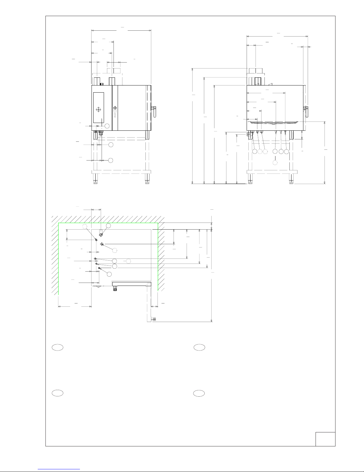
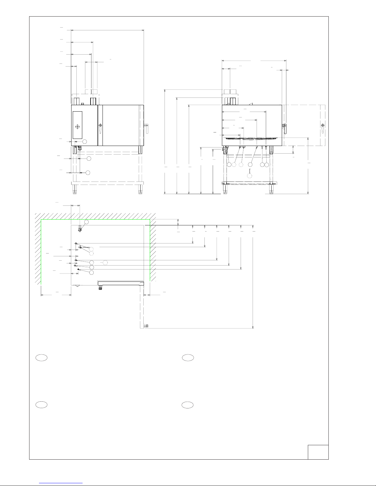
INSTALLATION DIAGRAM
SCHEMI DI INSTALLAZIONE
SCHEMAS D'INSTALLATION
ESQUEMA PARA LA INSTALACIÓN
SAFETY INSTRUCTIONS
Do not store or use gasoline or other flammable vapors or liquids in the vicinity of this or any other appliance.
WARNING: Improper installation, adjustment, alteration, service or maintenance can cause property damage,
injury or death. Read the installation, operating and maintenance instructions thoroughly before installing or
servicing this equipment.
Danger! Explosion hazard.
In the event a gas odor is detected, shut down equipment at the main shut-off valve. Immediatly call the emergency phone number
of your gas supplier.
Read each section of this manual before installing and operating.
PER LA VOSTRA SICUREZZA
Non immagazzinare o usare benzina o altri materiali infiammabili o liquidi nelle vicinanze di questa o qualsiasi
altra apparecchiatura.
AVVERTENZA: Installazione impropria, adattamenti, modifiche o manutenzione possono causare danni alla
proprieta` o morte. Leggere attentamente le istruzioni per l'installazione, il funzionamento e la manutenzione prima di
installare questa apparecchatura.
Pericolo! Pericolo di esplosione.
Nel caso in cui venga avvertito odore di gas spegnere l'apparecchiatura chiudendo la valvola principale a monte della stessa. Immediatamente
telefonare al numero d'emergenza del vostro fornitore di gas.
Leggere tutte le parti di questo manuale prima di installare o mettere in funzione l'apparecchiatura.
POUR VOTRE SECURITE
Il ne faut pas emmagasiner ou utiliser l’essence ou d’autres matériaux inflammables ou liquides à côté de cet
appareil ou d’autres appareils.
AVERTISSEMENT: L’installation, l’adaptation, la modification et l’entretien inadéquats peuvent causer des
dommages aux structures ou aux personnes et la mort. Lire attentivement les instructions d’installation, de fonctionnement
et d’entretien avant d’installer cet appareil.
Danger! Danger d’explosion.
Si l’on sent l’odeur de gaz, arrêter l’appareil en fermant la soupape principale en amont. Téléphoner immédiatement au numéro
d’urgence de votre fournisseur de gaz.
Lire toutes les parties de ce mode d’emploi avant d’installer ou mettre en fonction l’appareil.
PARA SALVAGUARDAR VUESTRA SEGURIDAD
No almacenar o utilizar gasolina u otros materiales inflamables o líquidos cerca de este u otros aparatos.
ADVERTENCIA: Una instalación indacuada, lo mismo que modificaciones y operaciones de mantenimiento
incorrectas pueden causar daños a la estructura y a las personas y provocar la muerte. Antes de instalar el aparato leer con
mucha atención las instrucciones de la instalación, del funcionamiento y del mantenimiento.
Peligro! Peligro de explosión.
En el caso que se sienta olor de gas, apagar inmediatamente el aparato cerrando la válvula principal colocada aguas arriba de
la misma. Llamar inmediatamente el número de teléfono de emergencia de la compañía erogadora del gas.
Leer todas las partes de este manual antes de llevar a cabo la instalación o de poner en marcha el aparato.
IT
CDN
ES
USA
IT
CDN
ES
USA
3
5938 036 01
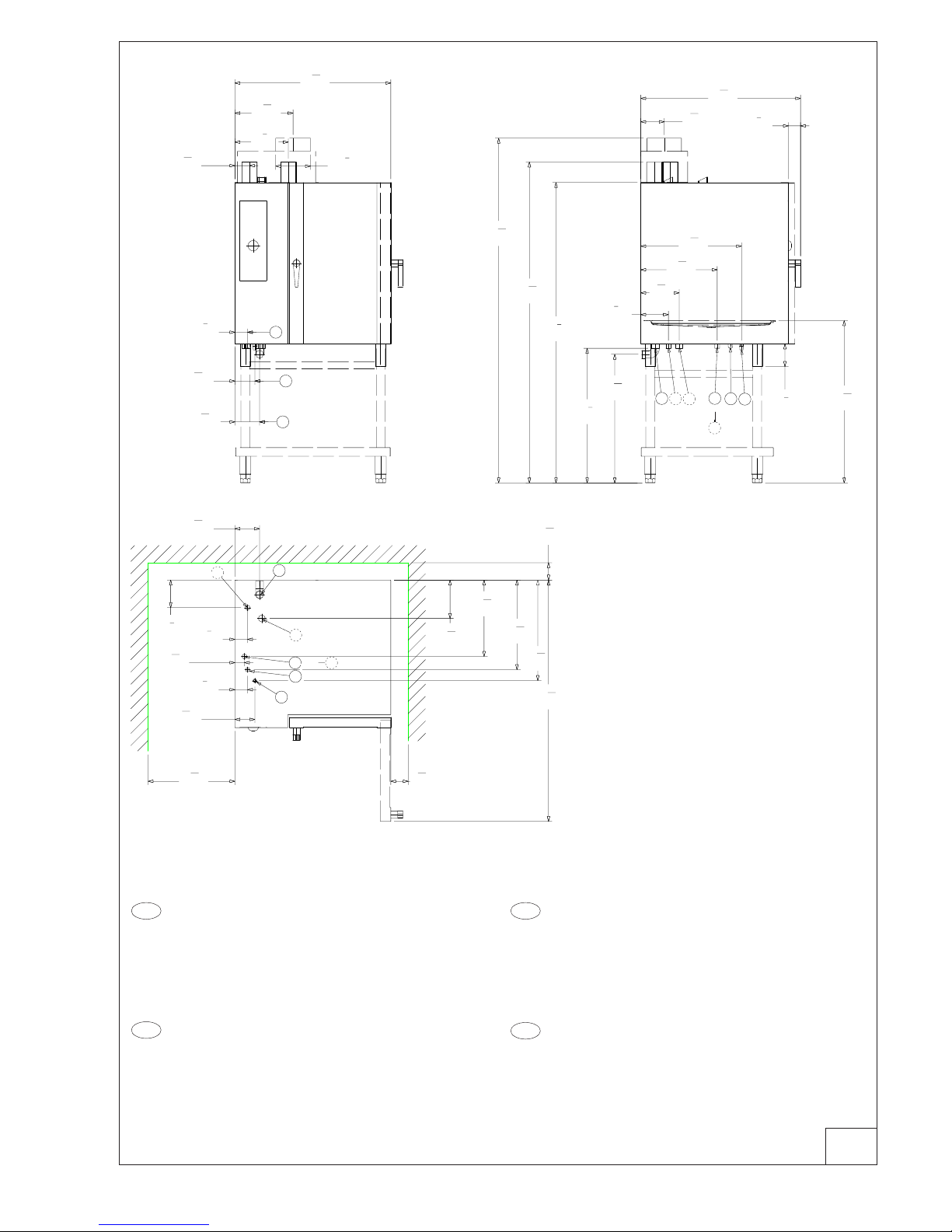
1a
USA
H - Gas connection ø1/2" NPT gasline
I - Power supply cable inlet
B - Water supply connection (0.5- 5 °F) ø3/4" NPT gasline
C - Water drain connection ø1"1/4 NPT gasline
N - Steam condens. water connection ø3/4" NPT gasline
D - Overflow drain pipe (AIR-BREAK) (Do not connect)
( ^) FUNCTIONAL LEVEL
IT
H - Attacco gas ø1/2" NPT gasline
I - Entrata cavo elettrico
B - Attacco alim. acqua (0,5 - 5 °F) ø3/4" NPT gasline
C - Collettore scarico acqua ø1"1/4 NPT gasline
N - Attacco acqua Conden. fumane ø3/4" NPT gasline
D - Scarico di sicurezza (AIR-BREAK) (Non collegare)
( ^) LIVELLO FUNZIONALE
CDN
H - Entée gaz ø1/2" NPT gasline
I - Entrée câble électrique
B - Entrée eau (0,5 - 5 °F) ø3/4" NPT gasline
C - Collecteur évacuation eau ø1"1/4 NPT gasline
N - Entrée eau Conden.vapeurs ø3/4" NPT gasline
D - Évacuation de secours (AIR-BREAK) (Ne pas raccorder)
( ^) NIVEAU FONCTIONNEL
E S
H - Conexión de gas ø1/2" NPT gasline
I - Ingreso cable eléctrico
B - Conexión de agua (0,5 - 5 °F) ø3/4" NPT gasline
C - Colector del desagüe ø1"1/4 NPT gasline
N - Entrada del agua de condensación ø3/4" NPT gasline
D - Desagüe de seguridad (AIR-BREAK) (No conectar)
( ^) NIVEL FUNCIONAL
4
17
32
"
115 mm
3
5
16
"
84 mm
13
3
16
"
335 mm
12
1
8
"
308 mm
35
11
32
"
898mm
6
3
32
"
155 mm
2
7
8
"
73 mm
7
7
8
"
Ø
200 mm
H
C
I
54
23
32
"
1390mm
5
19
32
"
142 mm
2
7
8
"
73 mm
2
5
32
"
55 mm
2
7
8
"
73 mm
4
17
32
"
115 mm
6
1
4
"
159 mm
17
5
16
"
440 mm
20
5
16
"
516 mm
8
11
16
"
221 mm
3
15
16
"
100 mm
3
15
16
"
100 mm
19
11
16
"
500 mm
C
B
I
H
N
D
cod. 597846800
30
1
2
"
775 mm
29
3
16
"
741.5 mm
58
9
32
"
1480 mm
62
15
16
"
1598.5 mm
68
5
16
"
1735 mm
36
7
32
"
920 mm
5
1
8
"
130 mm
5
5
16
"
135 mm
36
13
16
"
935 mm
2
3
4
"
70 mm
6
1
4
"
159 mm
8
11
16
"
221 mm
17
5
16
"
440 mm
22
27
32
"
580 mm
C
B
H
I
D
N
(A ^)
(C ^)
(A ^)
(B ^)
(A ^)
(B ^)
22
27
32
"
580 mm
(A ^)
(C ^)
(A ^)
(B ^)
(A ^)
(B ^)
B
B
Mod.: 6 GN 1/1
4
5938 036 01
4
21
32
"
118 mm
3
19
32
"
91mm
13
3
16
"
335 mm
14
11
32
"
364 mm
47
9
16
"
1208 mm
5
23
32
"
145 mm
2
15
32
"
62.5 mm
7
7
8
"
Ø
200 mm
H
C
I
67
17
32
"
1715 mm
3
1
16
"
77.5 mm
3
1
16
"
77.5 mm
2
15
32
"
62.5 mm
4
21
32
"
118 mm
11
27
32
"
301 mm
22
27
32
"
580 mm
26
5
16
"
668 mm
14
1
4
"
362 mm
3
15
16
"
100 mm
3
15
16
"
100 mm
19
11
16
"
500 mm
28
13
16
"
732 mm
C
B
I
H
N
D
cod. 597847800
30
1
2
"
775 mm
29
3
16
"
741 mm
58
9
32
"
1480 mm
62
29
32
"
1598mm
68
5
16
"
1735 mm
42
"
1067 mm
5
1
8
"
130 mm
5
5
16
"
135 mm
36
13
16
"
935 mm
2
3
4
"
70 mm
11
27
32
"
301 mm
14
1
4
"
362 mm
22
27
32
"
580 mm
28
13
16
"
732 mm
C
B
H
I
D
N
(A ^)
(C ^)
(A ^)
(B ^)
(A ^)
(B ^)
B
(A ^)
(B ^)
(A ^)
5
23
32
"
145 mm
(C ^)
(A ^)
(B ^)
B
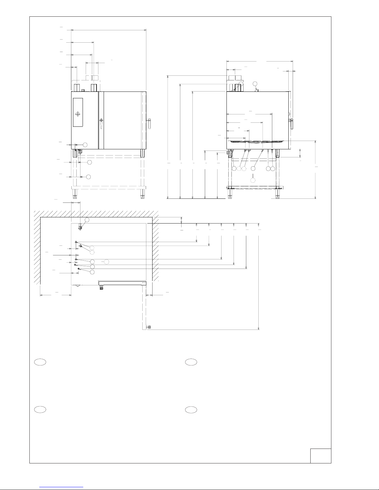
1b
USA
H - Gas connection ø1/2" NPT gasline
I - Power supply cable inlet
B - Water supply connection (0.5- 5 °F) ø3/4" NPT gasline
C - Water drain connection ø1"1/4 NPT gasline
N - Steam condens. water connection ø3/4" NPT gasline
D - Overflow drain pipe (AIR-BREAK) (Do not connect)
( ^) FUNCTIONAL LEVEL
IT
H - Attacco gas ø1/2" NPT gasline
I - Entrata cavo elettrico
B - Attacco alim. acqua (0,5 - 5 °F) ø3/4" NPT gasline
C - Collettore scarico acqua ø1"1/4 NPT gasline
N - Attacco acqua Conden. fumane ø3/4" NPT gasline
D - Scarico di sicurezza (AIR-BREAK) (Non collegare)
( ^) LIVELLO FUNZIONALE
CDN
H - Entée gaz ø1/2" NPT gasline
I - Entrée câble électrique
B - Entrée eau (0,5 - 5 °F) ø3/4" NPT gasline
C - Collecteur évacuation eau ø1"1/4 NPT gasline
N - Entrée eau Conden.vapeurs ø3/4" NPT gasline
D - Évacuation de secours (AIR-BREAK) (Ne pas raccorder)
( ^) NIVEAU FONCTIONNEL
ES
H - Conexión de gas ø1/2" NPT gasline
I - Ingreso cable eléctrico
B - Conexión de agua (0,5 - 5 °F) ø3/4" NPT gasline
C - Colector del desagüe ø1"1/4 NPT gasline
N - Entrada del agua de condensación ø3/4" NPT gasline
D - Desagüe de seguridad (AIR-BREAK) (No conectar)
( ^) NIVEL FUNCIONAL
Mod.: 6 GN 2/1
5
5938 036 01
4
17
32
"
115 mm
3
5
16
"
84 mm
13
3
16
"
335 mm
12
1
8
"
308 mm
35
11
32
"
898mm
5
19
32
"
142 mm
2
7
8
"
73 mm
7
7
8
"
Ø
200 mm
H
C
I
54
23
32
"
1390mm
5
19
32
"
142 mm
2
7
8
"
73 mm
2
5
32
"
55 mm
2
7
8
"
73 mm
4
17
32
"
115 mm
6
1
4
"
159 mm
17
5
16
"
440 mm
20
5
16
"
516 mm
8
11
16
"
221 mm
3
15
16
"
100 mm
3
15
16
"
100 mm
19
11
16
"
500 mm
C
B
I
H
N
D
cod. 597847300
30
1
2
"
775 mm
29
3
16
"
741.5 mm
68
1
8
"
1730 mm
72
25
32
"
1848.5 mm
78
5
32
"
1985 mm
36
7
32
"
920 mm
5
1
8
"
130 mm
5
5
16
"
135 mm
36
13
16
"
935 mm
2
3
4
"
70 mm
6
1
4
"
159 mm
8
11
16
"
221 mm
17
5
16
"
440 mm
22
27
32
"
580 mm
C
B
H
I
D
N
(A ^)
(C ^)
(A ^)
(B ^)
(A ^)
(B ^)
B
22
27
32
"
580 mm
(A ^)
(C ^)
(A ^)
(B ^)
(A ^)
(B ^)
B
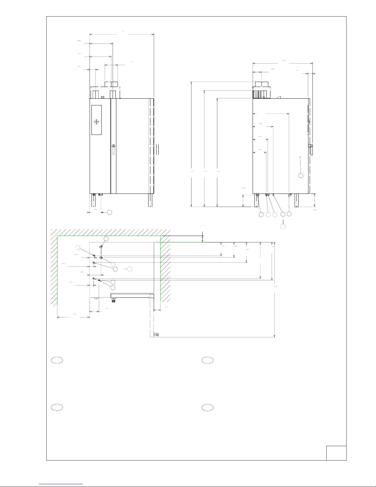
1c
Mod.: 10 GN 1/1
USA
H - Gas connection ø1/2" NPT gasline
I - Power supply cable inlet
B - Water supply connection (0.5- 5 °F) ø3/4" NPT gasline
C - Water drain connection ø1"1/4 NPT gasline
N - Steam condens. water connection ø3/4" NPT gasline
D - Overflow drain pipe (AIR-BREAK) (Do not connect)
( ^) FUNCTIONAL LEVEL
IT
H - Attacco gas ø1/2" NPT gasline
I - Entrata cavo elettrico
B - Attacco alim. acqua (0,5 - 5 °F) ø3/4" NPT gasline
C - Collettore scarico acqua ø1"1/4 NPT gasline
N - Attacco acqua Conden. fumane ø3/4" NPT gasline
D - Scarico di sicurezza (AIR-BREAK) (Non collegare)
( ^) LIVELLO FUNZIONALE
CDN
H - Entée gaz ø1/2" NPT gasline
I - Entrée câble électrique
B - Entrée eau (0,5 - 5 °F) ø3/4" NPT gasline
C - Collecteur évacuation eau ø1"1/4 NPT gasline
N - Entrée eau Conden.vapeurs ø3/4" NPT gasline
D - Évacuation de secours (AIR-BREAK) (Ne pas raccorder)
( ^) NIVEAU FONCTIONNEL
ES
H - Conexión de gas ø1/2" NPT gasline
I - Ingreso cable eléctrico
B - Conexión de agua (0,5 - 5 °F) ø3/4" NPT gasline
C - Colector del desagüe ø1"1/4 NPT gasline
N - Entrada del agua de condensación ø3/4" NPT gasline
D - Desagüe de seguridad (AIR-BREAK) (No conectar)
( ^) NIVEL FUNCIONAL
6
5938 036 01
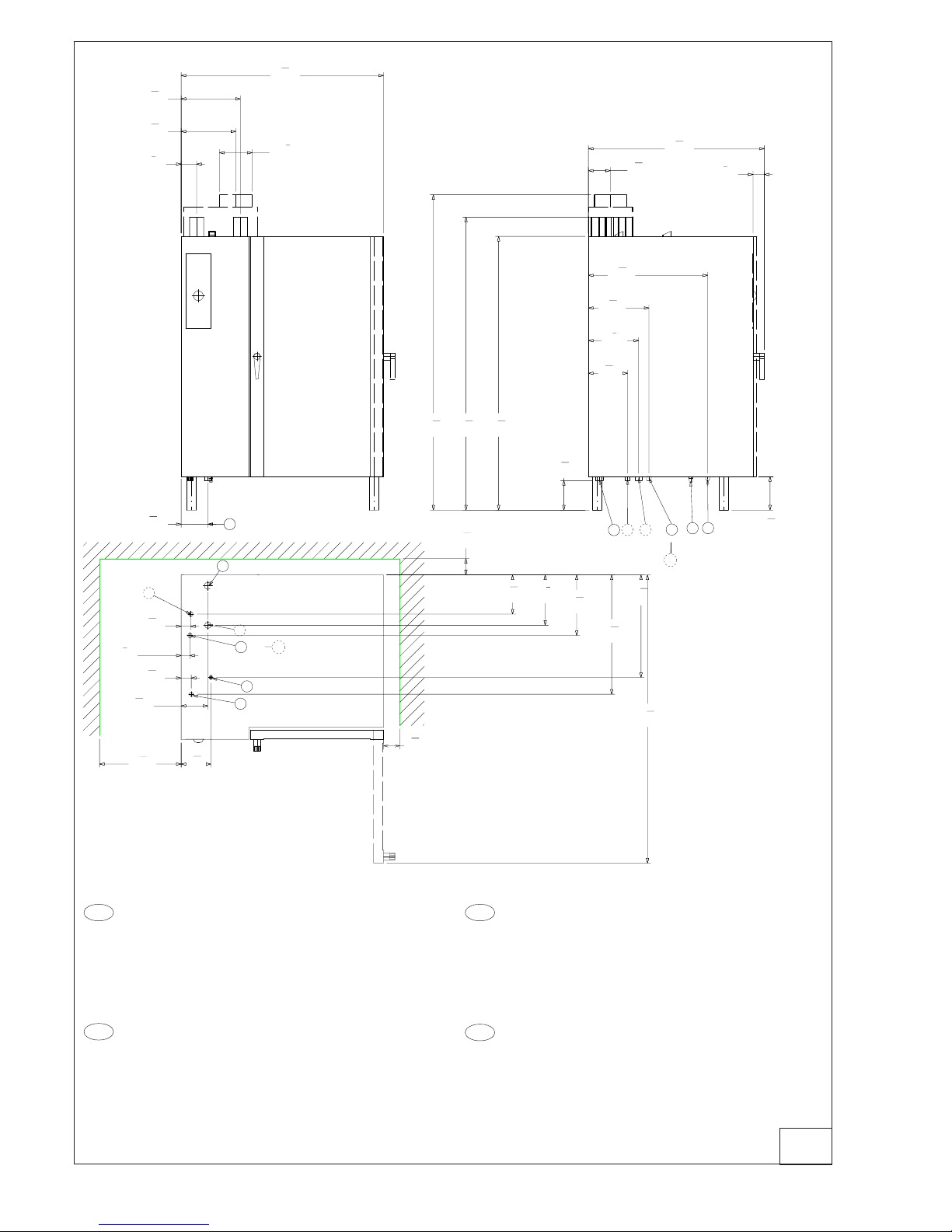
1d
4
21
32
"
118 mm
3
19
32
"
91mm
13
3
16
"
335 mm
14
11
32
"
364 mm
47
9
16
"
1208 mm
5
23
32
"
145 mm
2
15
32
"
62.5 mm
7
7
8
"
Ø
200 mm
H
C
I
67
17
32
"
1715 mm
3
1
16
"
77.5 mm
3
1
16
"
77.5 mm
2
15
32
"
62.5 mm
4
21
32
"
118 mm
11
27
32
"
301 mm
22
27
32
"
580 mm
26
5
16
"
668 mm
14
1
4
"
362 mm
3
15
16
"
100 mm
3
15
16
"
100 mm
19
11
16
"
500 mm
28
13
16
"
732 mm
C
B
I
H
N
D
cod. 597848300
30
1
2
"
775 mm
29
3
16
"
741 mm
68
1
8
"
1730 mm
72
3
4
"
1848 mm
78
5
32
"
1985 mm
42
"
1067 mm
5
1
8
"
130 mm
5
5
16
"
135 mm
36
13
16
"
935 mm
2
3
4
"
70 mm
11
27
32
"
301 mm
14
1
4
"
362 mm
22
27
32
"
580 mm
28
13
16
"
732 mm
P
U
C
B
H
I
D
N
(A ^)
(C ^)
(A ^)
(B ^)
(A ^)
(B ^)
B
(A ^)
(B ^)
(A ^)
(C ^)
(A ^)
(B ^)
B
5
23
32
"
145 mm
USA
H - Gas connection ø1/2" NPT gasline
I - Power supply cable inlet
B - Water supply connection (0.5- 5 °F) ø3/4" NPT gasline
C - Water drain connection ø1"1/4 NPT gasline
N - Steam condens. water connection ø3/4" NPT gasline
D - Overflow drain pipe (AIR-BREAK) (Do not connect)
( ^) FUNCTIONAL LEVEL
IT
H - Attacco gas ø1/2" NPT gasline
I - Entrata cavo elettrico
B - Attacco alim. acqua (0,5 - 5 °F) ø3/4" NPT gasline
C - Collettore scarico acqua ø1"1/4 NPT gasline
N - Attacco acqua Conden. fumane ø3/4" NPT gasline
D - Scarico di sicurezza (AIR-BREAK) (Non collegare)
( ^) LIVELLO FUNZIONALE
Mod.: 10 GN 2/1
CDN
H - Entée gaz ø1/2" NPT gasline
I - Entrée câble électrique
B - Entrée eau (0,5 - 5 °F) ø3/4" NPT gasline
C - Collecteur évacuation eau ø1"1/4 NPT gasline
N - Entrée eau Conden.vapeurs ø3/4" NPT gasline
D - Évacuation de secours (AIR-BREAK) (Ne pas raccorder)
( ^) NIVEAU FONCTIONNEL
E S
H - Conexión de gas ø1/2" NPT gasline
I - Ingreso cable eléctrico
B - Conexión de agua (0,5 - 5 °F) ø3/4" NPT gasline
C - Colector del desagüe ø1"1/4 NPT gasline
N - Entrada del agua de condensación ø3/4" NPT gasline
D - Desagüe de seguridad (AIR-BREAK) (No conectar)
( ^) NIVEL FUNCIONAL
7
5938 036 01
1e
3
21
32
"
93mm
13
3
16
"
335 mm
14
3
32
"
358 mm
39
1
8
"
994mm
6
15
16
"
176 mm
7
7
8
"
Ø
200 mm
C
57
23
32
"
1466 mm
2
29
32
"
74 mm
2
15
32
"
63 mm
2
5
16
"
59 mm
6
15
16
"
176 mm
8
7
32
"
209 mm
5
23
32
"
145 mm
12
13
32
"
315 mm
22
"
559 mm
9
7
32
"
234 mm
3
15
16
"
100 mm
19
11
16
"
500 mm
23
1
16
"
586 mm
3
15
16
"
100 mm
C
B
I
H
N
D
cod. 597848800
7
3
32
"
180 mm
66
1
32
"
1677 mm
70
21
32
"
1795mm
76
1
16
"
1932 mm
36
15
32
"
926 mm
8
1
16
"
205 mm
5
5
16
"
135 mm
2
3
4
"
70 mm
8
7
32
"
209 mm
22
"
559 mm
12
13
32
"
315 mm
9
7
32
"
234 mm
C
B
H
I
D
N
(A ^)
(C ^)
(A ^)
(B ^)
(A ^)
(B ^)
B
(A ^)
(B ^)
(A ^)
(C ^)
(A ^)
(B ^)
B
USA
H - Gas connection ø1" NPT gasline
I - Power supply cable inlet
B - Water supply connection (0.5- 5 °F) ø3/4" NPT gasline
C - Water drain connection ø1"1/4 NPT gasline
N - Steam condens. water connection ø3/4" NPT gasline
D - Overflow drain pipe (AIR-BREAK) (Do not connect)
( ^) FUNCTIONAL LEVEL
IT
H - Attacco gas ø1" NPT gasline
I - Entrata cavo elettrico
B - Attacco alim. acqua (0,5 - 5 °F) ø3/4" NPT gasline
C - Collettore scarico acqua ø1"1/4 NPT gasline
N - Attacco acqua Conden. fumane ø3/4" NPT gasline
D - Scarico di sicurezza (AIR-BREAK) (Non collegare)
( ^) LIVELLO FUNZIONALE
CDN
H - Entée gaz ø1" NPT gasline
I - Entrée câble électrique
B - Entrée eau (0,5 - 5 °F) ø3/4" NPT gasline
C - Collecteur évacuation eau ø1"1/4 NPT gasline
N - Entrée eau Conden.vapeurs ø3/4" NPT gasline
D - Évacuation de secours (AIR-BREAK) (Ne pas raccorder)
( ^) NIVEAU FONCTIONNEL
ES
H - Conexión de gas ø1" NPT gasline
I - Ingreso cable eléctrico
B - Conexión de agua (0,5 - 5 °F) ø3/4" NPT gasline
C - Colector del desagüe ø1"1/4 NPT gasline
N - Entrada del agua de condensación ø3/4" NPT gasline
D - Desagüe de seguridad (AIR-BREAK) (No conectar)
( ^) NIVEL FUNCIONAL
Mod.: 20 GN 1/1
8
5938 036 01
1f
Mod.: 20 GN 2/1
3
3
4
"
95mm
13
3
16
"
335 mm
14
9
32
"
363 mm
48
13
16
"
1240 mm
6
15
32
"
164 mm
7
7
8
"
Ø
200 mm
C
69
17
32
"
1766 mm
2
5
16
"
59 mm
2
1
8
"
54 mm
2
7
16
"
62 mm
6
15
32
"
164 mm
9
7
16
"
240 mm
7
5
32
"
182 mm
14
19
32
"
371 mm
28
25
32
"
731 mm
12
1
8
"
308 mm
3
15
16
"
100 mm
19
11
16
"
500 mm
24
23
32
"
628 mm
3
15
16
"
100 mm
C
B
I
H
N
D
cod. 597849300
7
3
32
"
180 mm
66
1
32
"
1677 mm
70
21
32
"
1795mm
76
1
16
"
1932 mm
42
15
32
"
1079 mm
8
1
16
"
205 mm
5
5
16
"
135 mm
2
3
4
"
70 mm
9
7
16
"
240 mm
28
25
32
"
731 mm
14
19
32
"
371 mm
12
1
8
"
308 mm
C
B
H
I
D
N
(A ^)
(C ^)
(A ^)
(B ^)
(A ^)
(B ^)
B
(A ^)
(B ^)
(A ^)
(C ^)
(A ^)
(B ^)
B
USA
H - Gas connection ø1" NPT gasline
I - Power supply cable inlet
B - Water supply connection (0.5- 5 °F) ø3/4" NPT gasline
C - Water drain connection ø1"1/4 NPT gasline
N - Steam condens. water connection ø3/4" NPT gasline
D - Overflow drain pipe (AIR-BREAK) (Do not connect)
( ^) FUNCTIONAL LEVEL
IT
H - Attacco gas ø1" NPT gasline
I - Entrata cavo elettrico
B - Attacco alim. acqua (0,5 - 5 °F) ø3/4" NPT gasline
C - Collettore scarico acqua ø1"1/4 NPT gasline
N - Attacco acqua Conden. fumane ø3/4" NPT gasline
D - Scarico di sicurezza (AIR-BREAK) (Non collegare)
( ^) LIVELLO FUNZIONALE
CDN
H - Entée gaz ø1" NPT gasline
I - Entrée câble électrique
B - Entrée eau (0,5 - 5 °F) ø3/4" NPT gasline
C - Collecteur évacuation eau ø1"1/4 NPT gasline
N - Entrée eau Conden.vapeurs ø3/4" NPT gasline
D - Évacuation de secours (AIR-BREAK) (Ne pas raccorder)
( ^) NIVEAU FONCTIONNEL
E S
H - Conexión de gas ø1" NPT gasline
I - Ingreso cable eléctrico
B - Conexión de agua (0,5 - 5 °F) ø3/4" NPT gasline
C - Colector del desagüe ø1"1/4 NPT gasline
N - Entrada del agua de condensación ø3/4" NPT gasline
D - Desagüe de seguridad (AIR-BREAK) (No conectar)
( ^) NIVEL FUNCIONAL
9
USA
5938 036 01
INSTRUCTIONS FOR INSTALLATION AND USE
Table of contents Page
- Installation diagram .......................................................... 2
- APPLIANCE IDENTIFICATION
ELECTRIC COMBI - CONVECT OVENS
260450-260510 26 046 2 260456
26045
260451-260511 26 046 3 260457
2604
°
**
°
**
°
**
400
230
200
6GN1/1
(AOS061E)
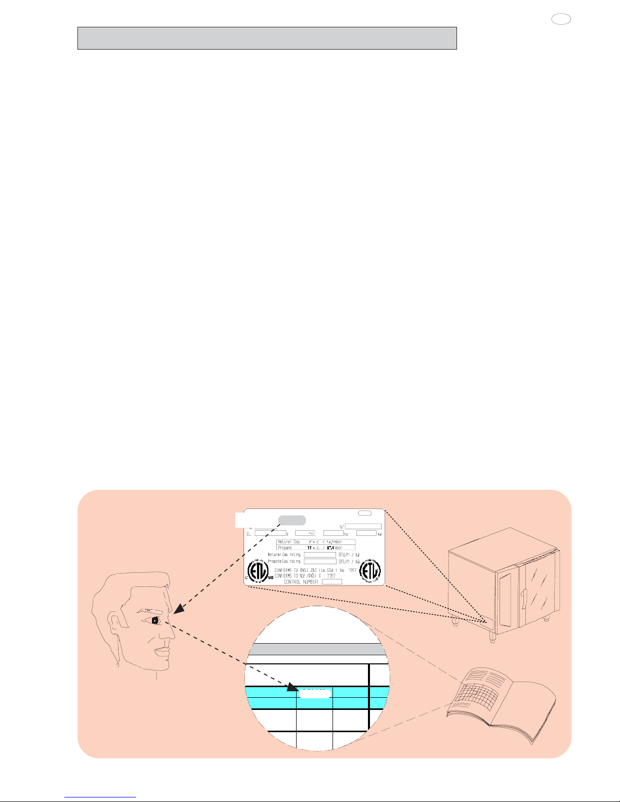
2. TABLE 1: TECHNICAL DATA
260462
Rating plate
PNC 9PDX 260462 05
- CONTROL PANEL FIGURES .......................................... 105
- Appliance identification .................................................... 9
I. MAIN FEATURES ............................................................. 10
1. Description of appliance ............................................. 10
2. Table 1: Technical data ................................................. 11
3. Precautions ..................................................................12
4. Safeguarding the environment ................................... 13
4.1 Packaging ..............................................................13
4.2 Use ......................................................................... 13
4.3 Cleaning ................................................................ 13
4.4 Disposal .................................................................13
II. INSTRUCTIONS FOR INSTALLATION ............................ 14
1. Place of Installation ..................................................... 14
1.1 Ventilation ................................................................ 14
1.2 Reference standards ............................................... 14
1.3 Unpackaging ........................................................... 14
1.4 Immediately inspect for shipping damage .............. 14
2. Positioning .....................................................................14
3. Combusted gas discharge .......................................... 14
3.1 Foreword.................................................................. 14
3.2
Installation of accessories ................................15
3.3 Warnings regarding the fluimg system .................. 15
4. Electrical connection................................................... 15
4.1 Installing the power supply cable .......................... 16
5. Water mains connection ............................................. 16
5.1 Water supply characteristics .................................. 16
5.2 Water drain system ................................................ 16
6. Gas connection ............................................................ 17
6.1 Warning.................................................................. 17
6.2 Nominal heat output .............................................. 17
6.3 Checking the supply pressure ............................... 17
7. Safety devices ............................................................. 18
8. Operation check .......................................................... 18
9. Servicing ....................................................................... 18
10. Troubleshooting ........................................................... 18
11. Layout of main components ...................................... 18
III. INSTRUCTIONS FOR USE ............................................. 19
1. Opening the oven door ................................................ 19
1.1 6- and 10-grid models ........................................... 19
1.2 20-GRID models .................................................... 19
2. Closing the oven door ................................................. 19
2.1 6- and 10-GRID models ......................................... 19
2.2 20-GRID models .................................................... 19
3. Description of the control panel ................................. 20
3.1 Introduction ............................................................ 20
3.2 Main controls ......................................................... 20
3.3 Main cooking modes ............................................. 20
3.4 Special cooking modes ......................................... 20
3.5 Additional functions ............................................... 21
USING THE OVEN ................................................................. 22
4. Introduction .................................................................. 22
4.1 Switching the oven on ........................................... 22
4.2 Selecting the controls ............................................ 22
4.3 Manual controls ..................................................... 22
4.4 Automatic controls ................................................. 26
5. Information and error codes ....................................... 29
6. SWITCHING off in the event of a fault ........................ 30
7. Care and maintenance ................................................30
7.1 Periodical maintenance of the BOILER ................. 31
7.2 Replacing CONSUMABLE components ............... 32
7.3 Special cleaning instructions................................. 32

10
USA
5938 036 01
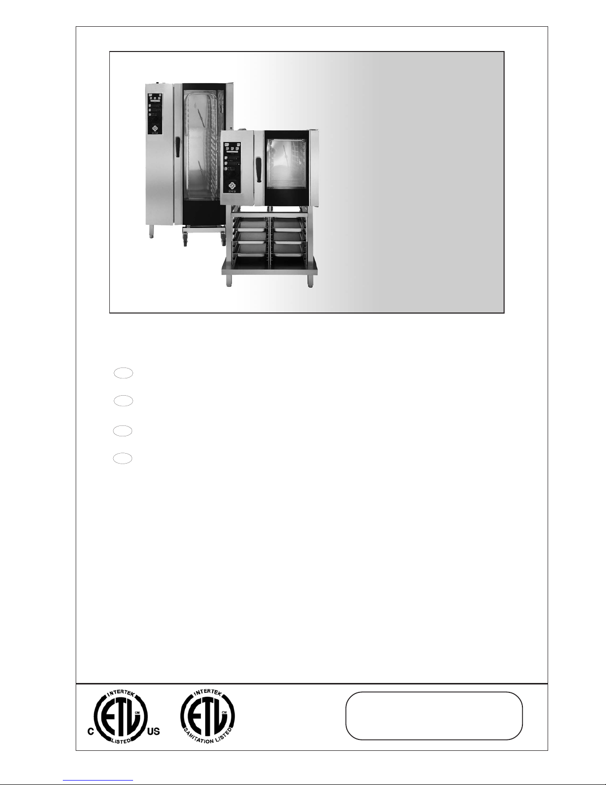
1. DESCRIPTION OF APPLIANCE
This booklet describes a number of appliance models.
For more detailed information about the model in your possession,
refer to "Technical Data" table 1.
The appliance has the following features:
• Digital temperature controlle.
• Thermostatic probe for measuring the core temperature of products (core temperature probe).
• Automatic flush to drain every two hour to prevent the build-up of
lime-scale in the boiler.
• Periodic draining and automatic washing of the boiler to prevent
the build-up of lime-scale (only available on certain models).
• Boiler lime-scale level indicator (see corresponding paragraph).
• Oven chamber automatic fast steam drain device for gratins.
• Air-break (anti-backup drain) device to prevent backflows from
the drain system from entering the oven (only available on certain
models).
• Halogen lighting in the cooking chamber.
• Double-action door opening safety mechanism designed to
protect the user from scalding steam (only available on certain
models).
• Double-glazed oven door for reduced heat dispersion into the
kitchen and low temperatures on the exterior of the oven.
• Daily oven chamber cleaning cycle (CLEANING SYSTEM)
.
• Self-diagnostics system indicating oven faults using error codes
(see "Information and error codes ").
I. MAIN FEATURES
 Loading...