

Page 1
OPERATOR’S MANUAL
with Illustrated Parts List
COCKTAIL AND
SLUSH FREEZERS
Models 876, 876B, 876C,
876RH, 876BRH, 876CRH
&
876B BATCH FREEZER
184633 — 5/16
H.C. Duke & Son, LLC. P/N 18633 May 2016 Printed In U.S.A.
Page 2

Page 3

Operator’s Manual
for
Electro Freeze
Counter and Floor Models
876, 876B, 876C,
876RH, 876BRH, 876CRH
Slush / Cocktail Freezers
&
876 Batch
Model Designations
B = Bar
C = Counter
RH = Refrigerated Hopper
BRH = Bar Refrigerated Hopper
CRH = Counter Refrigerated Hopper
All contents © Copyright 2016 H.C. Duke & Son, LLC., 2116 Eighth Avenue, East Moline, Illinois 61244
Page 4
ELECTRO FREEZE
Models 876, 876B, 876C, 876RH, 876BRH, 876CRH & 875 Batch
SAFETY FIRST!
Follow these four steps to safety ....
1. Recognize Safety Information ....Look for this
safety alert symbol throughout this manual.
When you see this symbol on your freezer or in this
manual, be alert to the potential for personal injury. Follow
recommended precautions and safe operating practices.
2. Understand Signal Words ....
The signal words — DANGER, WARNING and
DANGER
WARNING
CAUTION — are used with the safety alert symbol
(DANGER decals on the freezer may or may not have the
safety alert symbol, but the message is the same). Decals
with the words DANGER, WARNING or CAUTION appear
on the freezer. DANGER identies the most serious
hazard. Decals with the words DANGER or WARNING
are typically near specic hazards on the freezer. General
precautions are listed on CAUTION safety decals. In this
manual, CAUTION messages with the safety alert symbol
call attention to safety messages.
CAUTION
3. Follow Safety Instructions ....
Read and understand all safety messages in this manual.
Read and understand the decal safety messages on your
freezer. Take notice of the location of all decals on the freezer
and keep the safety decals in good condition. Check them
periodically and replace missing, damaged or illegible safety
decals. The safety decals must remain in place and legible
for the life of the freezer. If you need new decals, use the
information and illustrations on pages v and vi of this manual to
identify the decal and call or write to H.C. Duke & Son, LLC. or
local Electro Freeze distributor.
DO NOT attempt to operate the soft serve freezer until you
read and understand all safety messages and the operating
instructions in this manual.
iv 184633
Page 5
ELECTRO FREEZE
Models 876, 876B, 876C, 876RH, 876BRH, 876CRH & 875 Batch
SAFETY FIRST!
4. Definitions ....
Trained person (or Operator): A person who has been trained in the basic operation of
the freezer. This person is knowledgeable in the operation of machine startup, stopping,
lling, and basic cleaning, disassembly, washing, and sanitation of the freezer.
Freezer Technician: A person who has been trained by a factory representative, or
an experienced and qualied service person, to perform more complicated operations
such as freezer installation, maintenance repairs, component replacement , is aware of
hazards associated with electricity, moving parts, and takes necessary steps to protect
against injury to themselves and other people.
5. Operate Safely ....
IMPORTANT: Store Managers,owners, and supervisors must be aware of staff
capabilities and that they do not perform freezer operations outside their level of
knowledge or responsibility.
DO NOT allow untrained personnel to maintain or
service this freezer. Failure to follow this instruction
may result in severe personal injury. DO NOT operate
the freezer until all service and access covers are
secured with screws. DO NOT attempt to repair
the freezer until the main power supply has been
disconnected. Some freezers have more than one
disconnect switch. Contact your IDQ authorized
service representative or H.C. Duke & Son, LLC
Service Department for original equipment parts.
6. Caution ....
• This Freezer is to be operated by trained persons. The Dispense
feature, if used by public in self-serve applications, shall be monitored
by trained persons able to assist people with physical, sensory or mental
impaired capabilities.
• Children should not be allowed to play around this equipment.
• Do not store explosive substances such as aerosol cans with a ammable
propellant in freezer.
• This appliance is not designed for outdoor weather conditions and shall not be
exposed to rain.
• Do not wash machine with power sprayer. Do not install machine next to a power
sprayer where splash of freezer can occur.
• Machine is designed for use in areas of normal atmosphere. It is not to be used in
areas subject to explosion-proof standards.
184633 v
Page 6
ELECTRO FREEZE
Models 876, 876B, 876C, 876RH, 876BRH, 876CRH & 875 Batch
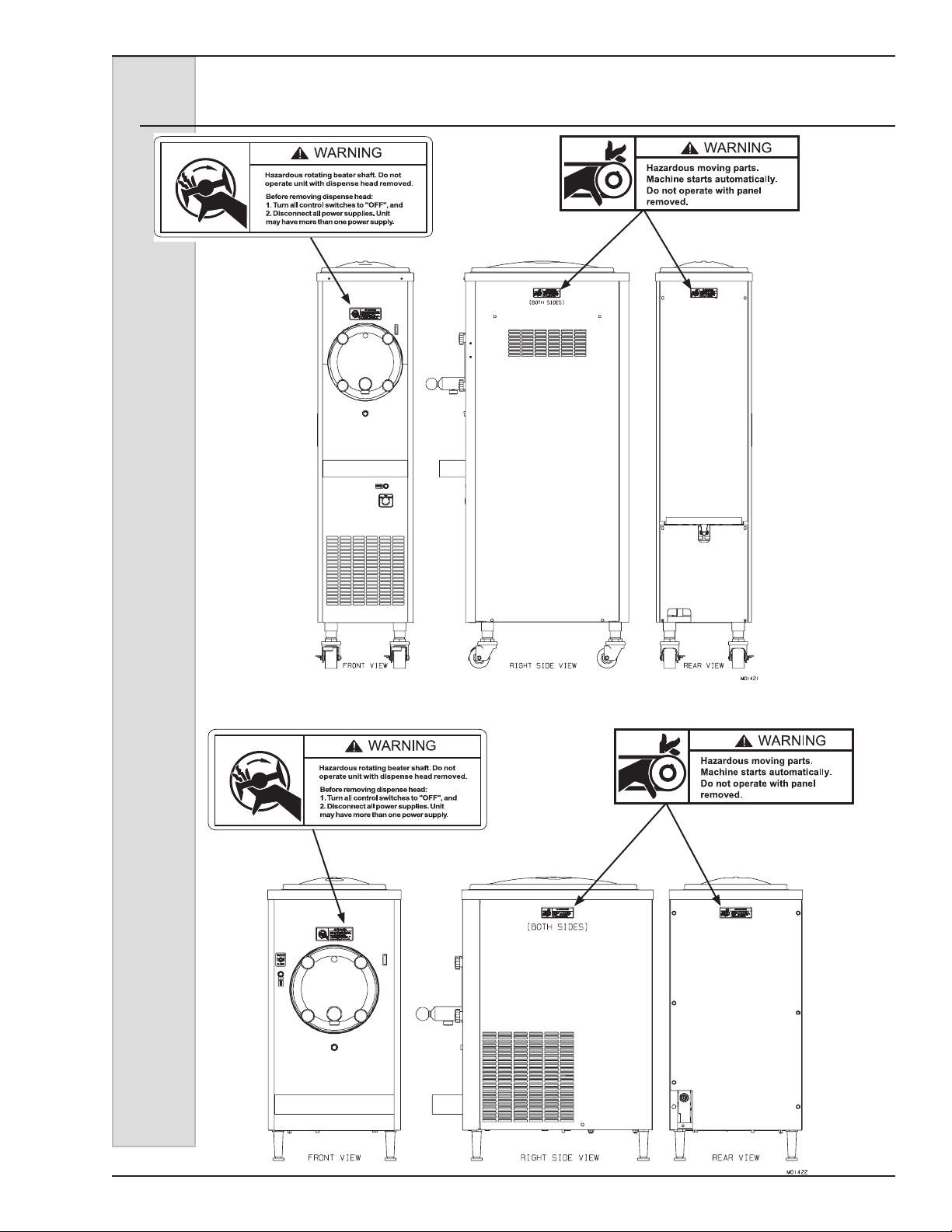
Safety Decal Locations
Do not attempt to operate the freezer
until all safety precautions and operating
instructions in this manual are read and
understood.
Take notice of all warning, caution,
instruction and information decals (or
labels) on the freezer as shown in the
gure to the right. The labels have been
put there to help maintain a safe working
environment.
The labels have been designed to
withstand washing and cleaning. All
labels must remain legible for the life of
the freezer. Check labels periodically
to be sure they can be recognized as
warning labels.
If it is necessary to replace any label,
please contact your local authorized
Electro Freeze Distributor or H. C. Duke
& Son, LLC. When ready to order, you will
need to determine the (1) part number,
(2) type of label, (3) location of label, and
(4) quantity required, and include a return
shipping address.
You may contact your local authorized
Electro Freeze Distributor, as follows:
Name: ________________________
Address: ______________________
Phone: ________________________
or — for factory service assistance —
contact H. C. Duke & Son, LLC. Electro
Freeze Service Department by phone or
FAX:
Phone: (309) 755-4553
(800) 755-4545
FAX: (309) 755-9858
E-mail: [email protected]
(The decals on the next page are
numbered 1, 2, and 3. Those numbers
correspond to the numbers in the table
below. The table provides the part
number, description, and quantity for
each decal.)
No. Part No. Description (Qty)
1 HC165126 Decal — Panel Removal (3) H
2 C165025 Decal — Beater Warning (1)
vi 184633
Page 7
ELECTRO FREEZE
Models 876, 876B, 876C, 876RH, 876BRH, 876CRH & 875 Batch
Safety Decal Locations
1
HC165025
2
HC165126
2
HC165126
1
HC165025
184633 vii
Page 8

ELECTRO FREEZE
Safety Decal Locations .............................................................vi
1 Introduction ................................................................1
2 Note to Installer ..........................................................1
3 Specications .............................................................5
4 Part Names and Functions ........................................8
Models 876, 876B, 876C, 876RH, 876BRH, 876CRH & 875 Batch
Table of Contents
2.1 Uncrating and Inspection .......................................2
2.2 Installation ..............................................................3
2.3 Electrical Requirements ......................................4
2.4 Electrical Connections ...........................................4
3.1 Particulars ..............................................................5
3.2 Data Plate ..............................................................6
3.3 Reference Information ...........................................6
3.4 Installation Date .....................................................6
3.5 Dimensions ............................................................7
3.6 WEEE (Waste Electrical and Electronic Equip.) ....7
5 Operator Controls and Indicators .............................10
5.1 Selector Switch (1) .................................................10
5.2 Circuit Breaker– Reset (2) .....................................10
5.3 Indicator Light – “ADD MIX” (3) .............................11
6 Disassembly and Cleaning ........................................12
6.1 Cleaning Accessories .............................................12
6.2 Disassembly Instructions .......................................13
6.3 Cleaning Instructions ............................................14
7 Assembly ....................................................................16
8 Start-up Instructions ..................................................19
8.1 Sanitizing ...............................................................19
8.2 Product Preparation ...............................................20
8.3 Priming ............................................................20
9 Closing Procedures ...................................................21
9.1 Draining Product ....................................................21
10 Slush Product Information ........................................22
10.1 Determining Product Consistency ........................22
10.2 Adjusting Product Consistency ...........................22
10.1 Refractometer/Brix Reading .................................23
11 Routine Maintenance .................................................24
13 Troubleshooting Tables .............................................42
viii 184633
Page 9

ELECTRO FREEZE
Figure 1 Pull Valve Door Assembly ..............................1
Figure 2 Spigot Door Assembly (Optional) ..................2
Figure 3 Beater Shaft Assembly ...................................3
Figure 4 Electrical Box ..................................................4
Figure 6 Panels — Counter Models) .............................8
Figure 7 Panels — Floor Models (sheet 1 of 2) ............10
Figure 8 Water Cooled Assembly View .......................12
Figure 9 Water Cooled Assembly View ........................14
Figure 10 Air Cooled Assembly (Page 1 of 2) ................ 16
Models 876, 876B, 876C, 876RH, 876BRH, 876CRH & 875 Batch
Part 2
Replacement Parts
Figure 11 Drive Shaft and Bearing Assembly ................ 18
Figure 12 Consistency Control .......................................19
Figure 13 Motor and Bearing Assembly .........................20
Figure 13 Motor and Bearing Assembly .........................21
Accessories .....................................................22
Figure 14 Accessory - Merchandiser ..............................23
*Refer to Part II Table of Contents for help with locating part numbers and illustrations.
184633 ix
Page 10

Page 11

ELECTRO FREEZE
Models 876, 876B, 876C, 876RH, 876BRH, 876CRH & 875 Batch
1 Introduction
Models 876, 876C, 876RH and 876CRH
are specically designed to dispense
a high quality, smooth-frozen, noncarbonated, water and sugar based drink
that is served in a variety of avors. The
product can be a neutral base or a pre-
mixed avor. Models 876B and 876BRH
are designed to dispense a variety of
smooth-frozen alcoholic drinks with less
than 8% alcohol.
NOTE: Models 876RH, 876BRH, and
876CRH, with refrigerated hopper, are
required when drinks containing perishable products are to be dispensed.
This manual has been prepared to assist
you in the proper operation and general
maintenance of the Electro Freeze Model
876, 876B, 876C, 876RH, 876BRH and
876CRH freezers.
The freezer will not compensate for, or
correct, any assembly or priming errors
made during the initial start-up. Therefore,
it is important that you follow the assembly and priming procedures detailed in
this manual.
Be sure all personnel responsible for
equipment operation completely read and
understand this manual before operating
the freezer. When properly operated and
maintained, this freezer will produce a
consistent quality product.
If you require technical assistance, please
contact your local authorized Electro
Freeze Distributor, as follows:
Name __________________________
Address: ________________________
_________________________
Phone: _________________________
For factory service assistance — contact
H. C. Duke & Son, LLC., Electro Freeze
Service Department as follows:
Phone: (309) 755-4553
(800) 755-4545
FAX: (309) 755-9858
E-mail: [email protected]
2 Note to Installer
This freezer must be installed and serviced by an Electro Freeze Distributor or
authorized service technician in accordance with the installation instructions.
After installation the warranty registration card must be completed and
returned to validate the warranty.
184633 1
Page 12
ELECTRO FREEZE
Models 876, 876B, 876C, 876RH, 876BRH, 876CRH & 875 Batch
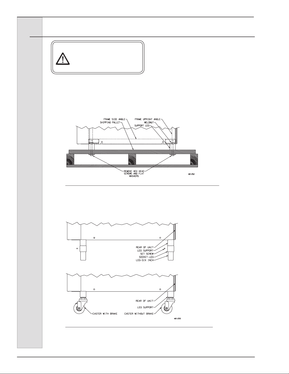
2.1 Uncrating and Inspection
CAUTION
Be sure to properly support
the machine when removing
bolts and installing legs or
casters.
When the unit is received and while
the carrier is still present, inspect the
shipping carton for any damage that
may have occurred in transit. If the
SHOCKWATCH® label indicates red and/
or the carton is broken, torn, or punctured,
Figure 2-1 Machine Bolted to Shipping Base
note the damage on the carrier’s freight
bill and notify the carrier’s local agent
immediately.
1. Remove the carton from the
pallet, and move the machine as close as
possible to the permanent location.
2. Remove the shipping bolts on
the bottom of the freezer (gure 2-1) and
install either the legs or casters (gure
2-2).
FRONT BACK
NOTE: Screw casters
or legs all the way in
coupling, then adjust
out to level with 1/4
inch slope to front.
Figure 2-2 Installing Mounting Legs or Casters
2 184633
Page 13

ELECTRO FREEZE
2.2 Installation
Models 876, 876B, 876C, 876RH, 876BRH, 876CRH & 875 Batch
CAUTION
All materials and connections
must conform to local
requirements and be in
compliance with the National
Electrical Code.
1. This freezer is designed for indoor use
and must be protected from outdoor
weather conditions.
2. Where codes permit, Electro Freeze
recommends that the freezer be
installed on casters and have exible
water and electrical connections for
easier service and cleaning.
3. All models require a minimum 6 inch
(15 cm) clearance on either the side
panels or the rear panel for adequate
ventilation. Freezers designed with
top air discharge require at least 18
inches (45 cm) above the top panel be
free of obstructions. Anything blocking
ventilation of the freezer (including
cone dispensers) will reduce the
efciency of the freezer.
4. Water cooled double models will
require a 1/2” MPT water inlet and
water waste connection. Both water
condensers are tied together so that
one water inlet and one water waste
is all that is required. The connections
are found on the bottom under the
compressor mounting area and are
clearly tagged - “Water Inlet” and
“Water Waste”. A manual shut-off
valve should be installed in the water
inlet line at the time of installation.
The water pressure must be between
35-140 psig (241-965kPa) for proper
operation.
5. Water cooled and air cooled remote
freezers require at least 12 inches
(30 cm) above the top panel be free
of obstructions. Anything blocking
ventilation of the freezer (including
cone dispensers) will reduce the
efciency of the freezer.
6. Place the freezer in the nal location
and level the machine by adjusting
the legs or casters so that the unit
is level side-to-side, and the front
is approximately ¼” lower than the
rear, to allow proper drainage of the
freezing cylinder.
7. Water Cooled Do not allow freezer to
be in ambient where air temperature
goes below 0°C (32°F),the freezing
temperature of water.
8. Water consumption increases if
temperature of entering water is
above 20°C (65°F)
184633 3
Page 14
ELECTRO FREEZE
Models 876, 876B, 876C, 876RH, 876BRH, 876CRH & 875 Batch
2.3 Electrical Requirements
CAUTION
To prevent accidental electrical
shock, a positive earth ground
is required.
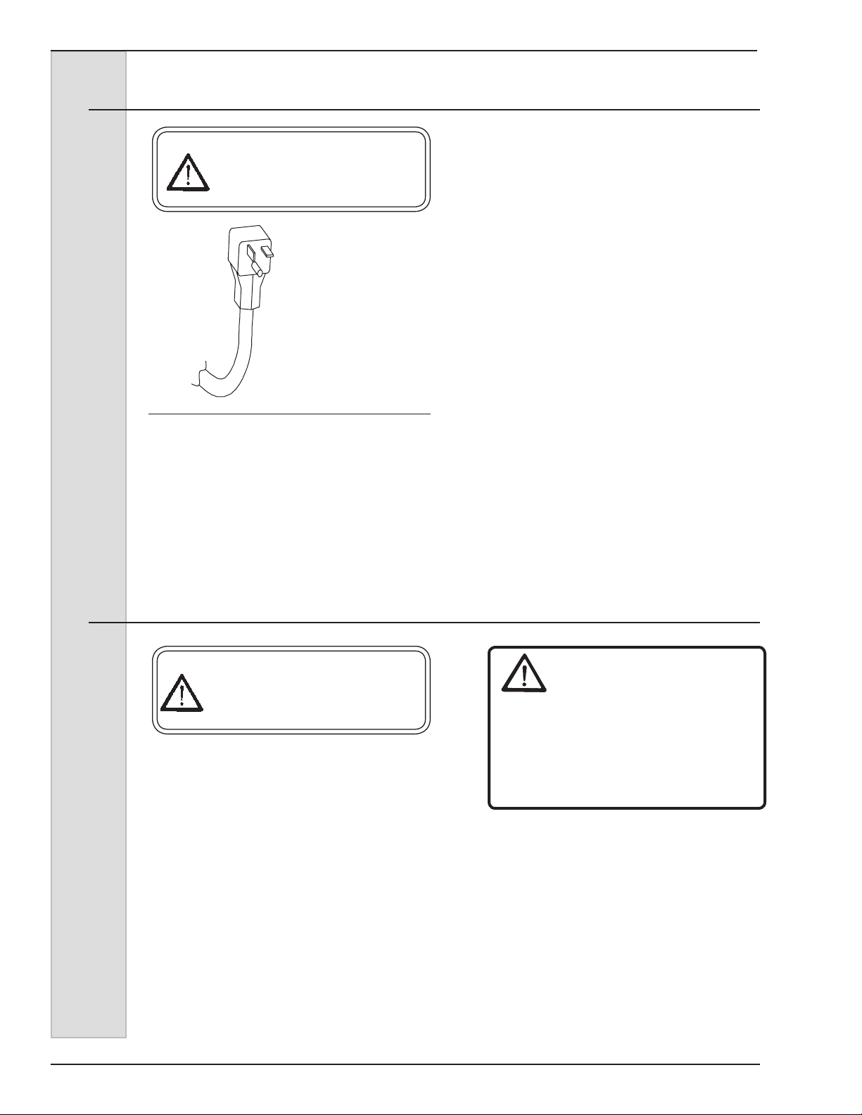
Plug Rating:
20A, 125VAC
(For use with a NEMA
“5-20R” Receptacle)
Figure 2-3 Plug
1. Always verify electrical specications
on the data plate (see gure 3-1) of
each individual freezer. Data plate
specications will always supersede
the information in this manual.
2. Refer to the data plate on the rear
panel for connection of proper fuse or
HACR circuit breaker.
3. Refer to the wiring diagram provided
for proper power connections.
4. All 115 volt 20 amp freezers are
supplied with a factory power
cord (Figure 2-3) that requires a
NEMA “5-20 R” type receptacle to
accommodate the plug. All freezers
should be connected to a circuit
separate from any other electrical
equipment.
5. Supply voltage must be within ±
10% of the voltage indicated on the
nameplate. Request your local power
company to correct any voltage
problem.
6. For 3 phase freezers, beater shaft
rotation must be clockwise as viewed
from the front of the freezer.
2.4 Electrical Connections
CAUTION
To prevent accidental electrical
shock, a positive earth ground
is required.
1. Double freezers with two compressors
require one power supply for each
side of the freezer. Each side of the
freezer operates independently.
2. Check the data plate for fuse
size, wire ampacity and electrical
specications.
3. Refer to the wiring diagram provided
for proper power connections.
4. Electrical connections are made in the
junction box located mid-level behind
the left side panel.
WARNING
Warning: When installing the machine,
insert an all pole disconnect, adequately
sized according to freezer nameplate
marking with electrical contact spacing
of 3mm minimum. This should be within
sight of the freezer.
5. Use a exible connection when
permissible. All materials and
connections must conform to local
codes and the National Electrical
Code.
6. For 3 phase freezers, beater shaft
rotation must be clockwise as viewed
from the front of the freezer.
4 184633
Page 15

ELECTRO FREEZE
Models 876, 876B, 876C, 876RH, 876BRH, 876CRH & 875 Batch
3 Specifications
3.1 Particulars
Always check and verify voltage and amperage on the data
plate located on the back panel of each freezer.
Counter Models - 876B, 876C, 876BRH, 876CRH
Floor Models - 876, 876RH
COUNTER FLOOR
Width (in/cm) 17/43 14.5/37
Height (in/cm) .................................36/92 59.5/151
Depth (in/cm) ...................................25/64 25/64
Weight (lbs/kg) .................................255/116 280/127
Compressor Cylinder ......................75 HP / 5,500 BTUH
.56 kw (Motor) 1.6 kw (Cooling)
Beater Motor ..................................25 HP / .19 kw
Refrigerant (Cylinder/Cabinet) ......404a
Charge .............................................2.25 lb / 1.02 kg
Cooling ............................................Air or Water
Cylinder ...........................................20 Qts / 18.9 Liters
Noise: The Steady acoustic pressure level, for both air cooled and water cooled freezers,
is less than 70dB(A).
Water Cooled units: Water consumption increases if
temperature of entering water is above 20°C (65°F)
*Contact factory for other voltages.
*** Do not add mix above line marked on side of mix
tank wall.
184633 5
Page 16
ELECTRO FREEZE
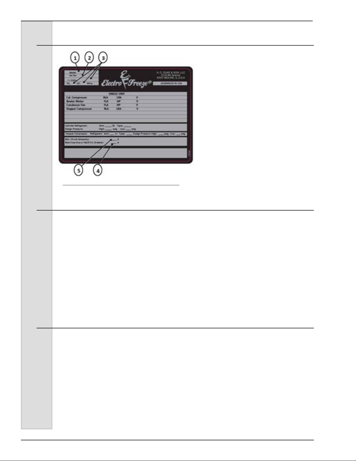
3.2 Data Plate
Figure 3-1
Figure 3-1 Data Plate
Models 876, 876B, 876C, 876RH, 876BRH, 876CRH & 875 Batch
The data plate provides important
information that the operator should
record and have available for parts
ordering, warranty and service requests.
3.3 Reference Information
Write in
Reference
Information HERE!
Fill in this information as soon as you
receive the Electro Freeze GEN-80
Shake Freezer. The item numbers,
encircled, correspond with the call-out
numbers in gure 3-1.
3.4 Installation Date
Fill in the date of installation, and the name, address, and phone number of the
installer in the space provided below. This information will be needed when ordering
parts or service for the freezer.
Date of installation: _____________________________________________
1.) Model Number: ________________
2.) Serial Number: ________________
3.) Electrical Spec: Voltage _________
4.) Phase _________Hertz _________
5.) Maximum Fuse Size: ____________
6.) Minimum Circuit Ampacity: ________
Installed by: ___________________________________________________
Address: _____________________________________________________
Phone: _______________________________________________________
6 184633
Page 17
ELECTRO FREEZE
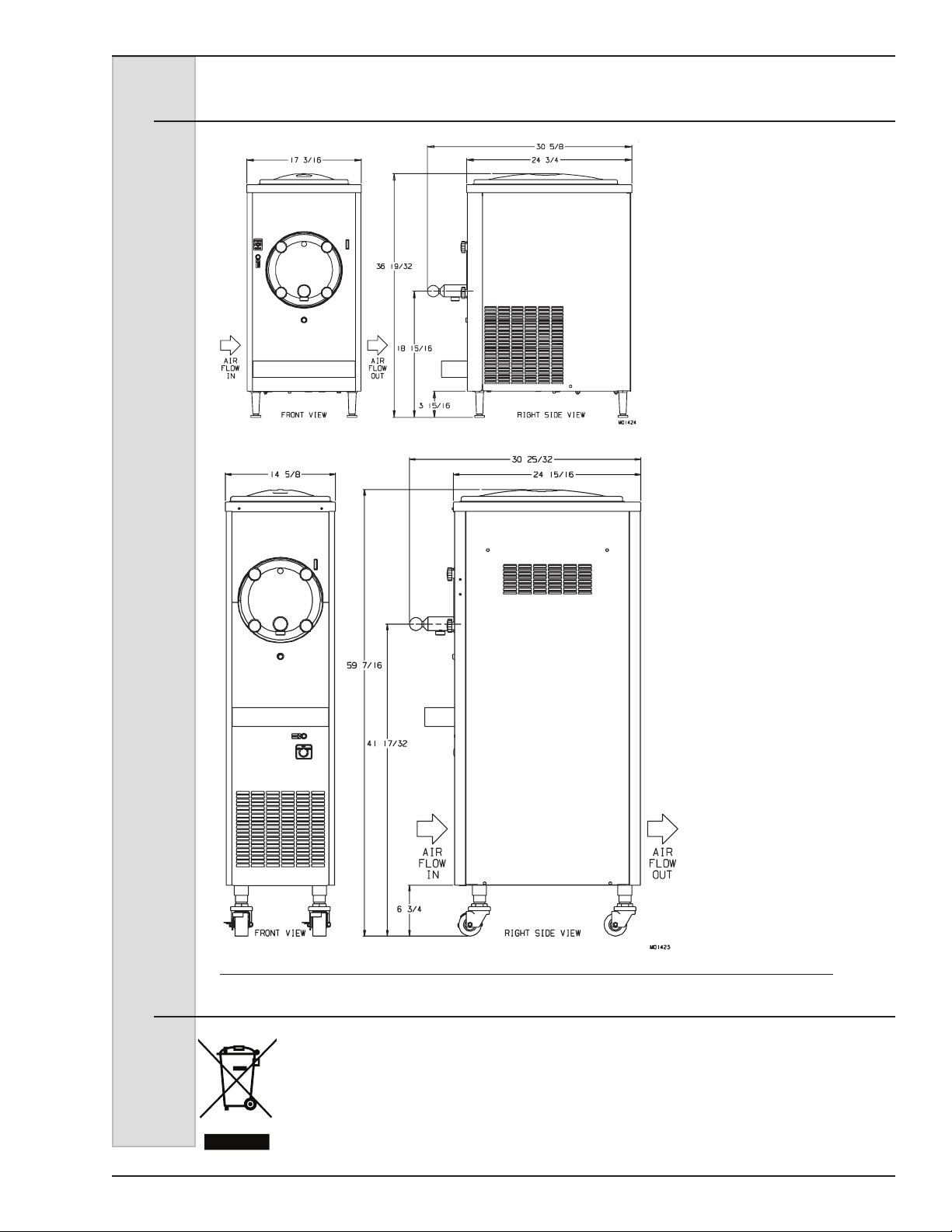
3.5 Dimensions
Models 876, 876B, 876C, 876RH, 876BRH, 876CRH & 875 Batch
876B, 876C,
876BRH &
876CRH
Counter Models
876 and 876RH
Floor Models
Figure 3-2 Dimensions
3.6 WEEE (Waste Electrical and Electronic Equipment)
In conformity with EU 2002/96/EC,
this freezer, at the end of life cycle,
is not to be discarded with normal
urban waste. Instead, it is the user’s
responsibility to dispose of this product
by returning it to a collection point
designated for the recycling of electrical,
electronic components and separation
of reclaimable, recyclable materials.
Contact your local distributor or authority
for correct disposal.
184633 7
Page 18
ELECTRO FREEZE
Models 876, 876B, 876C, 876RH, 876BRH, 876CRH & 875 Batch
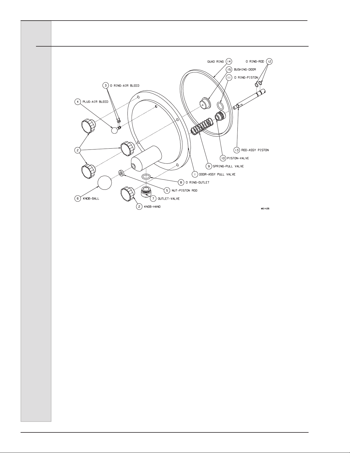
4 Part Names and Functions
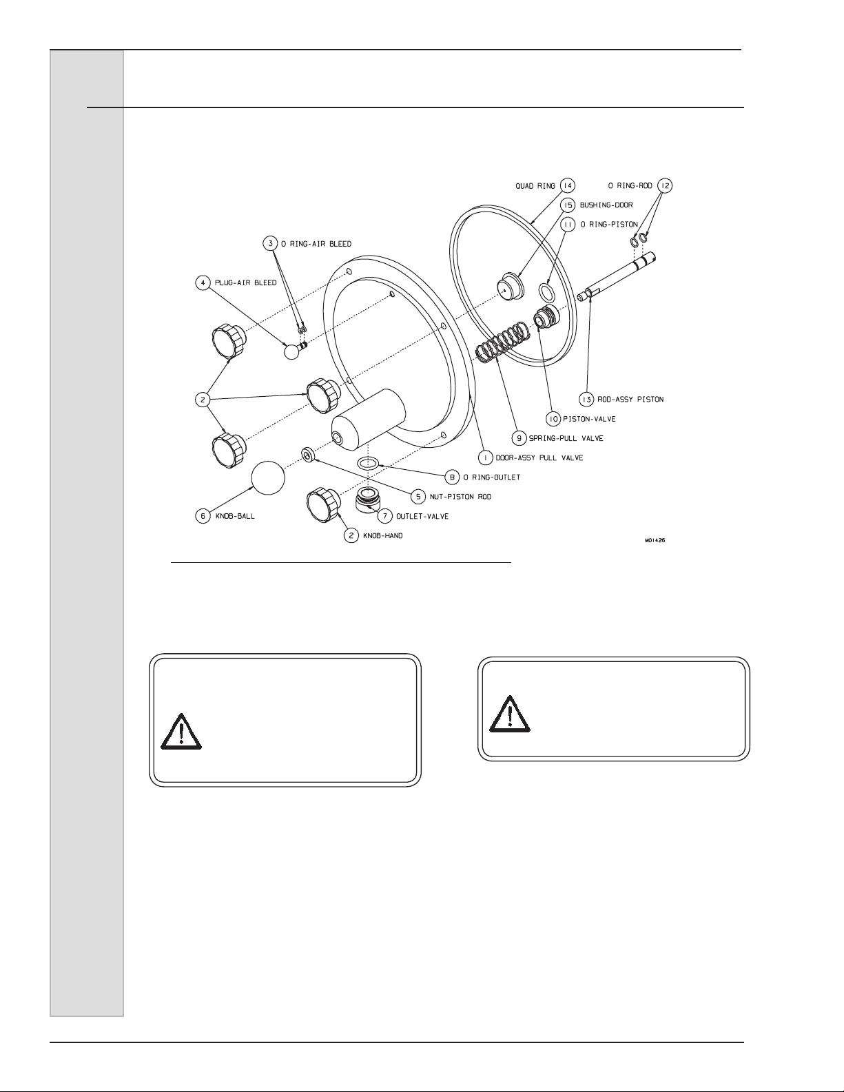
1.) DOOR (HEAD): Encloses the
freezing cylinder and provides an
opening for product to be dispensed.
2.) KNOB - HAND: Secures the door
(head) to the freezing cylinder.
3.) O-RING - AIR BLEED: Seals the air
bleed plug in the dispense head.
4.) PLUG - AIR BLEED: Seals the air
bleed opening in the head when
closed. Allows air to be removed
from the cylinder in the lling
process.
5.) NUT - PISTON ROD: Keeps piston
assembly from going into the
cylinder if the ball knob is removed.
6.) KNOB - BALL (DISPENSE): Used
to open and close the piston to start
and stop the ow of product from the
freezer.
7.) OUTLET-VALVE: Shapes the frozen
product as it is dispensed.
9.) SPRING - PISTON: Enables the
piston to self close after dispensing.
10.) PISTON: Seals the product opening
in the head when closed. Allows
product to ow when open.
11.) O-RING - PISTON: Seals the piston
in the head. Must be lubricated to
seal and glide properly.
12.) O-RING - ROD: Holds the piston in
place on the rod.
13.) ROD - ASSY. PISTON: Attaches
piston to the knob ball for
dispensing.
14.) QUAD-RING - HEAD: Seals the
head to the freezing cylinder. Must
be lubricated.
15.) BUSHING - HEAD: Supports and
aligns the beater shaft in the head.
Must be lubricated.
8.) O-RING - OUTLET: Seals the valve
outlet in the head.
8 184633
Page 19
ELECTRO FREEZE
Models 876, 876B, 876C, 876RH, 876BRH, 876CRH & 875 Batch
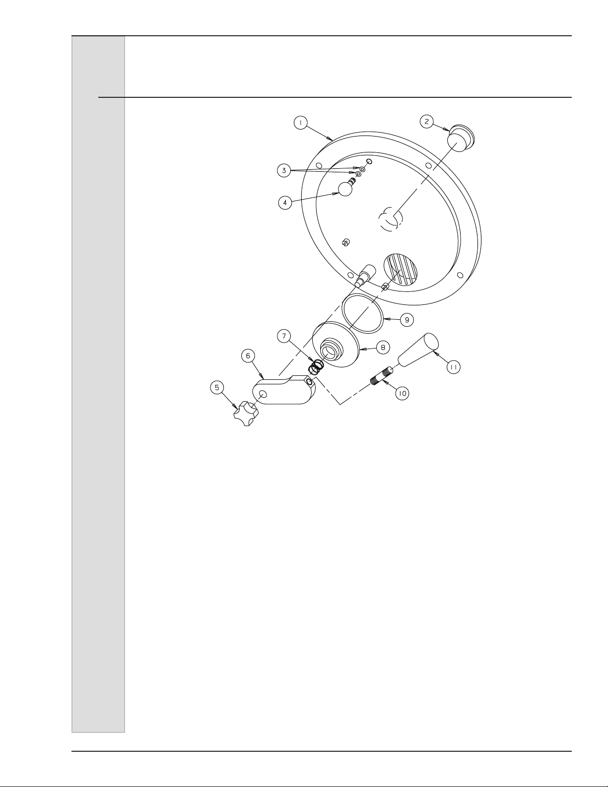
4 Part Names and Functions
(876B BATCH ONLY)
1.) DOOR (HEAD): Encloses the
freezing cylinder and provides an
opening for product to be dispensed.
2.) BUSHING - HEAD: Supports and
aligns the beater shaft in the head.
Must be lubricated.
3.) O-RING - AIR BLEED: Seals the air
bleed plug in the dispense head.
4.) PLUG - AIR BLEED: Seals the air
bleed opening in the head when
closed. Allows air to be removed
from the cylinder in the lling
process.
5.) KNOB - HAND: Secures the
pivot valve assembly to the door
assembly.
6.) BAR - PIVOT GUIDE: Used to open
and close the pivot valve to start
and stop the ow of product from the
freezer.
7.) SPRING - VALVE: Holds pivot valve
against head.
8.) BODY - PIVOT VALVE: Used to
start and stop the ow of product
from the freezer.
9.) O-RING - PIVOT VALVE: Seals the
pivot valve to the head. Must be
lubricated to seal and glide properly
10.) BAR - HANDLE: Used to open and
close the pivot valve.
11.) HANDLE - TAPERED BLACK:
Used to open and close the pivot
valve.
184633 9
Page 20
ELECTRO FREEZE
Models 876, 876B, 876C, 876RH, 876BRH, 876CRH & 875 Batch
4 Part Names and Functions (continued)
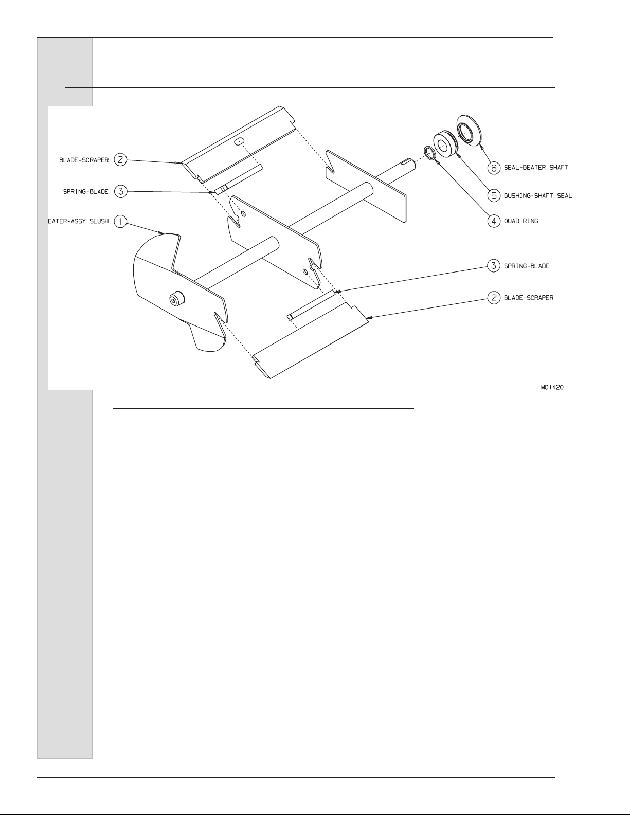
Figure 4-2 Beater Shaft Assembly
1.) BEATER - ASSY. SLUSH: Rotates
in the freezing cylinder to keep
product blended.
2.) BLADE - SCRAPER: Scrapes the
frozen product from the freezing
cylinder wall.
3.) SPRING - BLADE: Holds the blade
against the cylinder wall.
4.) QUAD-RING: Seals between the
beater and the shaft seal bushing.
Must be lubricated.
5.) BUSHING - SHAFT SEAL: Holds
the cup seal to the beater shaft.
Must be lubricated.
6.) SEAL (CUP) - BEATER SHAFT:
Seals the opening between the
freezing cylinder and the beater
shaft.
10 184633
Page 21
ELECTRO FREEZE
Models 876, 876B, 876C, 876RH, 876BRH, 876CRH & 875 Batch
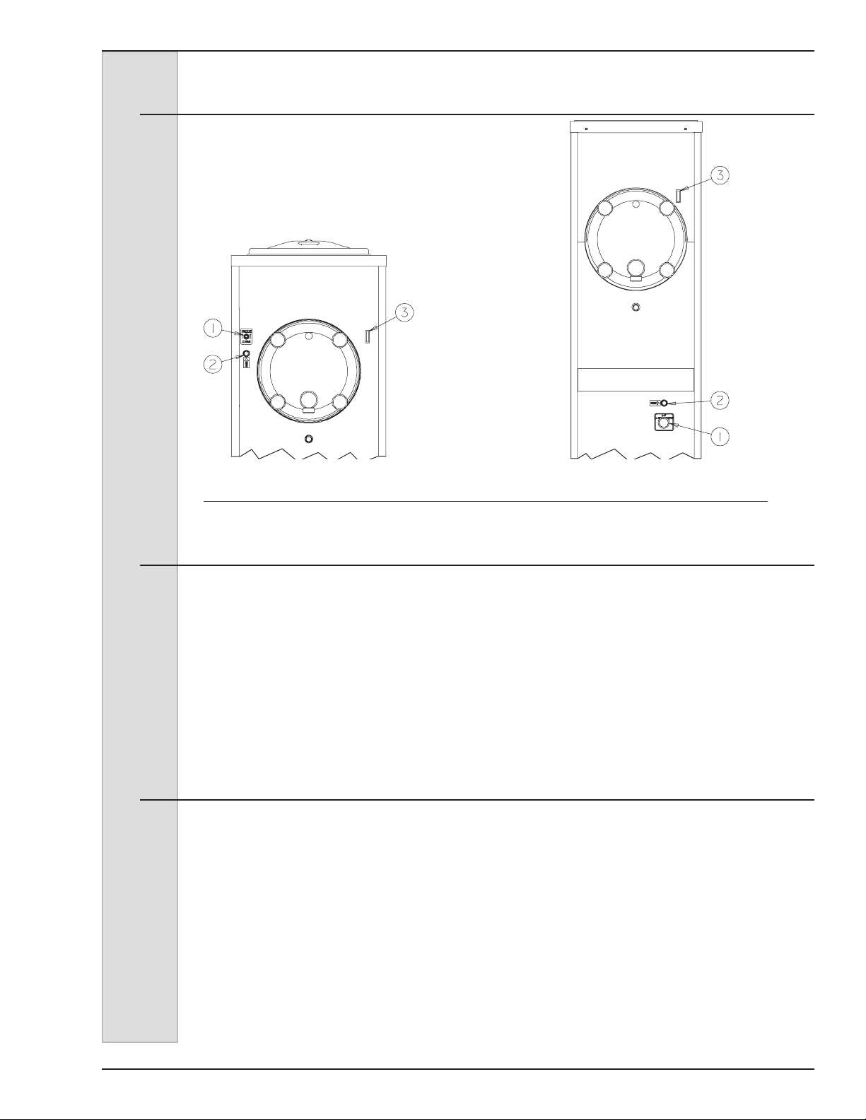
5 Operator Controls and Indicators
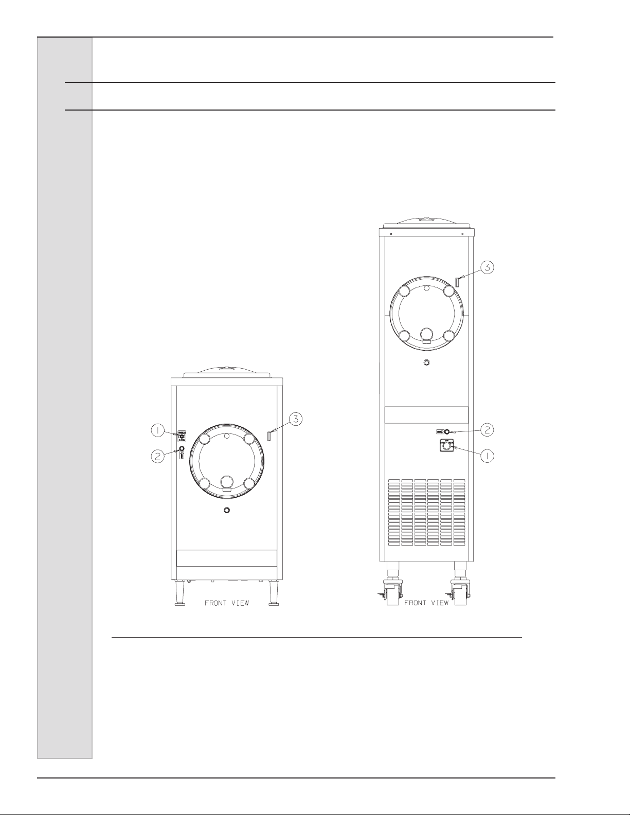
The following paragraphs describe the
operator controls and indicators. Refer to
gure 5-1 for location of these controls
and indicators on the freezer.
Figure 5-1 Counter Models 876B, 876C,
876BRH, and 876CRH Floor Models 876 and 876RH
5.1 Selector Switch (1)
This three-position switch controls the
functions of your freezer.
a. “CLEAN” — This position operates
the beater only (no refrigeration).
Always use this position in all cleaning
and sanitizing operations.
b. “OFF” (center) — In this position
the beater motor and refrigeration
system will not operate.
5.2 Circuit Breaker– Reset (2)
This control protects the beater motor
against failure from an overload condition
by automatically shutting down the
freezer. To restart the freezer properly,
turn the selector switch to “OFF”, wait 2-3
minutes, then depress the reset button
and turn the selector switch back to the
“FREEZE” or “CLEAN” position.
Important:
Do not use the “FREEZE” position with
water or sanitizer in the cylinder or
hopper. Freezing water or sanitizer in
the cylinder or hopper will damage the
freezer.
c. “FREEZE” — This position
activates both the beater motor and
refrigeration unit. This is the normal
operating position.
Important:
If the overload trips frequently,
your freezer should be checked for
proper product consistency and
voltage. Contact your Electro Freeze
Distributor.
184633 11
Page 22
ELECTRO FREEZE
Models 876, 876B, 876C, 876RH, 876BRH, 876CRH & 875 Batch
5 Operator Controls and Indicators (cont.)
5.3 Indicator Light – “ADD MIX” (3) Optional
Important:
If proper mix level is not maintained, a
freeze-up may occur and damage the
freezer.
When blinking, this light indicates the mix
in the hopper is low and should be relled
as soon as possible. Always maintain
at least 2 inches (5.1 cm) of mix in the
hopper. For best operating results, keep
hopper full.
Figure 5-1 Counter Models 876B, 876C,
876BRH, and 876CRH Floor Models 876 and 876RH
12 184633
Page 23
ELECTRO FREEZE
Models 876, 876B, 876C, 876RH, 876BRH, 876CRH & 875 Batch
6 Disassembly and Cleaning
It is important that the freezer be
disassembled, washed, lubricated and
sanitized before operation.
The cleaning and sanitizing instructions
explained in this manual are required to
maintain a clean, sanitary freezer. The
freezer should be disassembled, cleaned,
reassembled, lubricated and sanitized
to ensure the best possible product and
freezer operation. Persons assembling,
cleaning or sanitizing the freezer must
rst wash their hands with an approved
sanitizer.
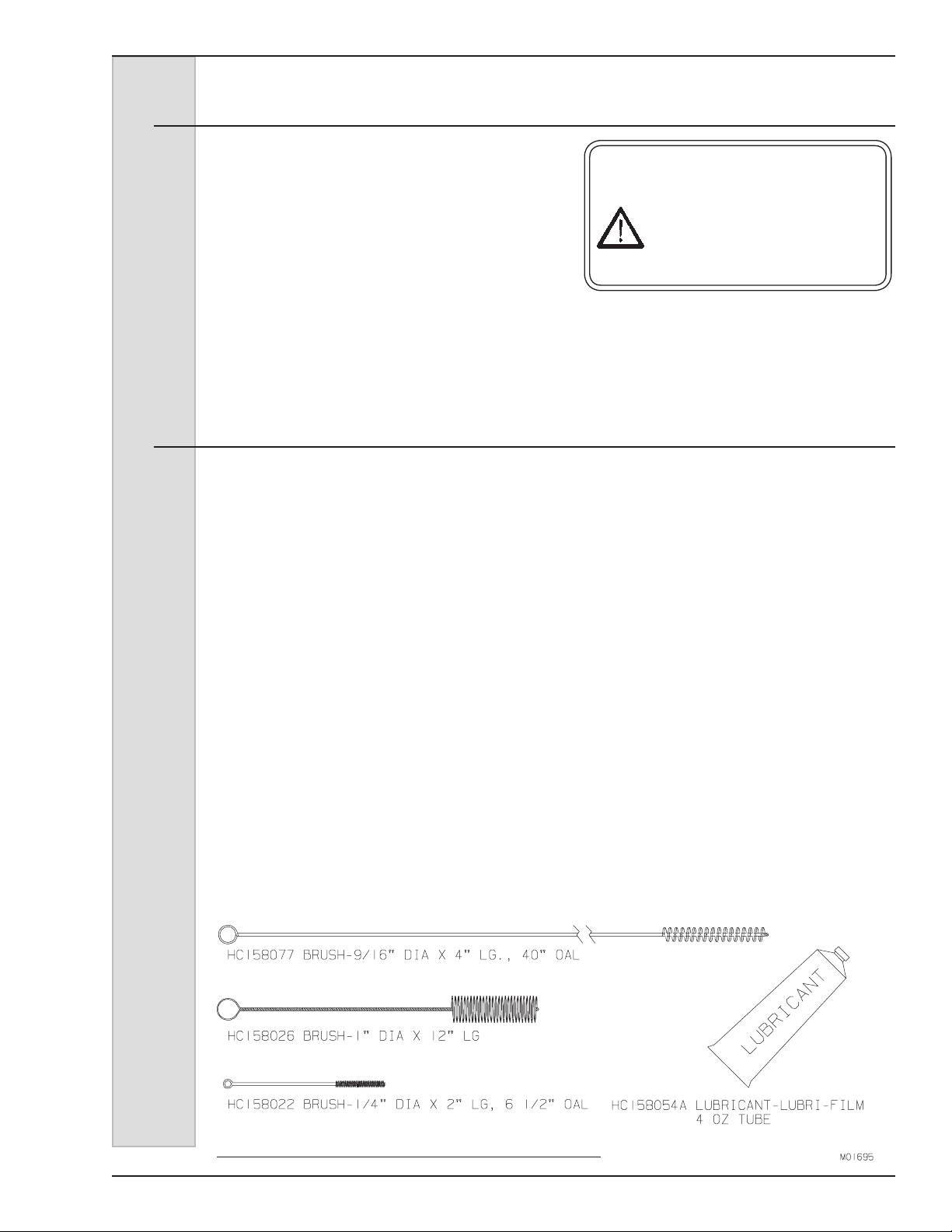
6.1 Cleaning Accessories
The following accessories are shipped with your freezer and are used when
cleaning and sanitizing your freezer:
1.) HC158077 BRUSH: 9/16-inch
diameter with a 36-inch handle used
for cleaning the drain tubes and mix
inlet tube.
CAUTION
To avoid electrical shock or
contact with moving parts,
make sure all switches are in
the “OFF” position and that
the main power supply is
disconnected.
2.) HC158026 BRUSH: 1-inch diameter
with 12-inch handle.
General parts cleaning.
3.) HC158022 BRUSH: 1/4-inch
diameter with an overall length of
6-1/2 inches. General parts cleaning.
4.) HC158000A LUBRICANT:
Approved lubricant for moving parts
and O-rings. See Assembly, Section
8 for lubricating points.
Figure 7-1 Cleaning Accessories
184633 13
Page 24
ELECTRO FREEZE
Models 876, 876B, 876C, 876RH, 876BRH, 876CRH & 875 Batch
6.2 Disassembly Instructions
The following accessories shipped with the freezer are necessary for cleaning,
sanitizing, and disassembly/assembly:
Figure 7-2
1. If there is product in the freezer, refer
to Closing Procedures, Draining
Product, Section 9.1.
CAUTION
To avoid electrical shock or
contact with moving parts,
make sure all switches are in
the “OFF” position and that
the main power supply is
disconnected.
2. Remove the four hand knobs (gure
6-2, item 2) and pull the dispensing
door (1) straight out.
3. Remove the ball knob (6), nut (5),
air bleed plug (4) and valve outlet (7)
from the door (1).
4. Remove the piston assembly (10, 11,
12, 13) and spring (9) by pushing the
piston rod (13) through the back of the
door (1).
CAUTION
To prevent bacteria growth,
remove all O-rings when
cleaning. Failure to do so could
create a health hazard.
5. Remove the O-rings (11) from the
piston and O-ring (12) from the piston
rod. Remove the O-ring (8) from the
valve outlet (7). Remove two O-rings
(3) from the air bleed plug (4).
6. Remove the door bushing (15) from
the door (1) or end of the beater.
7. Remove the door quad ring (14) from
the face of the freezer.
14 184633
Page 25

ELECTRO FREEZE
Models 876, 876B, 876C, 876RH, 876BRH, 876CRH & 875 Batch
6.2 Disassembly Instructions (cont.)
Figure 6-3
Figure 6-4
6.3 Cleaning Instructions
NOTE: It is your responsibility to be
aware of the requirements for meeting
federal, state and local laws concerning
the frequency of cleaning and sanitizing
your freezer.
CAUTION
Electric shock hazard. Do
not splash water on switches
orallowwatertoowonto
electrical components inside
the machine.
1. Prepare a three compartment sink
for cleaning parts removed from the
freezer, per applicable health codes.
Also prepare a clean surface to air-dry
all parts.
8. Remove the beater assembly (gure
6-3) from the cylinder.
9. Remove scraper blades (2), springs
(3), shaft seal (5 and 6) and quad ring
(4) from the beater (1).
10. Remove the seal from the bushing on
the shaft seal assembly as shown in
gure 6-4.
11. Remove hopper cover, drip tray and
insert.
CAUTION
To prevent bacteria growth,
remove ALL O-rings when
cleaning. Failure to do so could
create a health hazard.
Important:
Do not use unapproved sanitizers
or laundry bleach. These materials
may contain high concentrations of
chlorine and will chemically attack
freezer components.
184633 15
Page 26
ELECTRO FREEZE
Models 876, 876B, 876C, 876RH, 876BRH, 876CRH & 875 Batch
6.3 Cleaning Instructions (cont.)
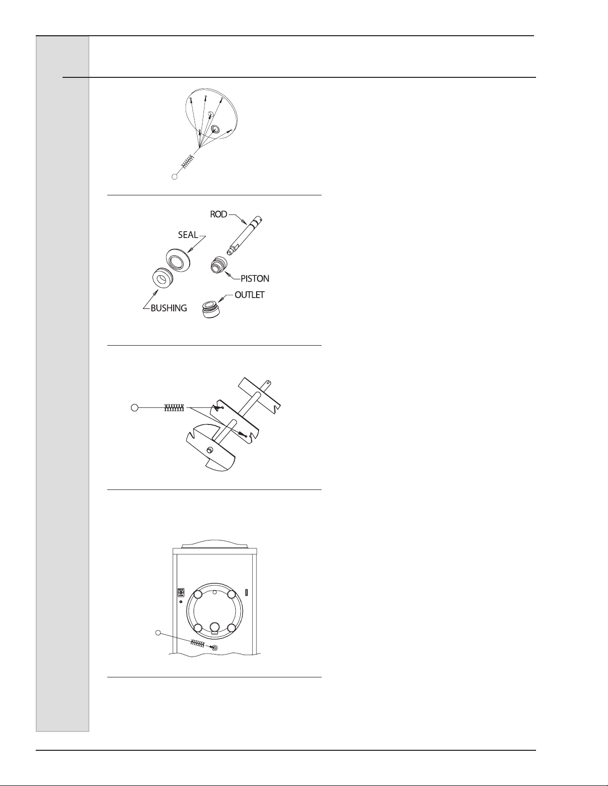
Figure 6-5 Clean Head
Figure 6-6 Clean piston rod, shaft seal,
bushing and outlet
NOTE: The sanitizer should be mixed
according to the manufacturer’s
instructions to yield 100 PPM available
chlorine solution. (example: Stera-Sheen
Green Label.) Use warm water (100° to
110°F or 38° to 43°C) to wash, rinse, and
sanitize.
2. Wash all parts removed from the
freezer thoroughly with a mild dish
detergent solution. Clean the following
parts with the appropriate supplied
brush:
a. The head piston openings, bushing
cavities, air bleed hole, dispense
outlet, mounting holes and mix ports,
as shown in gure 6-5.
b. The shaft seal, bushing, valve
outlet, piston, rod and O-ring grooves
as shown in gure 6-6.
c. The beater shaft inside spring
mounting holes and the scraper blade
mounting indentations, as shown in
gure 6-7.
Figure 6-7 Clean Beater
Figure 6-7 Clean Drain Tube
IMPORTANT:
Do not leave parts in sanitizer for more
than 15 minutes.
3. After ALL parts are washed, rinse
and place in the sanitizing solution.
For proper sanitizing, the parts must
remain fully immersed in the sanitizer
for 5 minutes. Allow parts to air-dry
after sanitizing.
4. Use a mild dish detergent solution to
clean the following, then rinse with
water:
a. Wipe down the freezer and
thoroughly brush out the inside of the
hopper, hopper cover, and mix feed
port to the cylinder.
b. Brush the inside of the cylinder
and make certain to clean the back
wall.
c. Brush the inside of the drain tube,
as shown in gure 6-8.
16 184633
Page 27

ELECTRO FREEZE
7 Assembly
Figure 7-1 Shaft Seal Assembly
Models 876, 876B, 876C, 876RH, 876BRH, 876CRH & 875 Batch
Correct assembly of the freezer is
essential to prevent leakage of the
product and damage to the freezer. To
assemble the freezer you will need an
approved sanitary lubricant. Make sure
all parts of the assemblies have been
washed and sanitized before assembling.
Persons assembling the freezer must
rst wash and sanitize their hands and
forearms with an approved sanitizer.
CAUTION
To avoid electrical shock or
contact with moving parts,
make sure all switches are in
the “OFF” position and that
the main power supply is
disconnected.
Figure 7-2 Lubricate Quad Ring
Figure 7-3 Attach Springs to Beater
1. Assemble the seal on the bushing
to complete the beater shaft seal
assembly (see gure 7-1). Apply
a thin lm of an approved sanitary
lubricant to the internal surface
and the face of the plastic bushing
opposite the bell-shaped portion of
the seal assembly. Do not allow any
lubricant to come into contact with the
bell-shaped rubber cup portion of the
seal assembly.
2. Slide the quad ring (gure 7-2, item 1)
over the rear of the beater shaft and
apply a liberal amount of lubrication.
3. Install the shaft seal assembly (2)
over the rear of the beater shaft, with
the bell-shaped portion facing the rear
and the bushing portion against the
quad ring.
4. Attach the blade springs to the beater
plates, as shown in gure 7-3.
5. Insert scraper blades into the proper
beater plate slots so that the end of
the spring rests in the groove on the
bottom side of the blade.
– continued
184633 17
Page 28
ELECTRO FREEZE
Models 876, 876B, 876C, 876RH, 876BRH, 876CRH & 875 Batch
7 Assembly (continued)
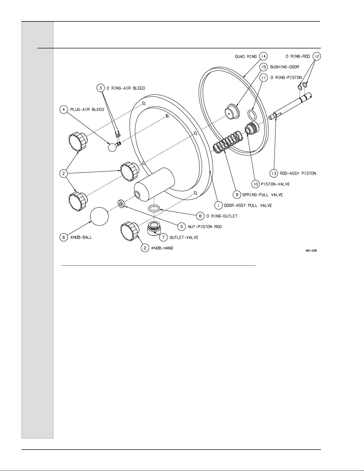
Figure 7-4 Head Assembly
6. Insert the assembled beater into the
cylinder by placing the rear blade
on the bottom of the cylinder and
depressing the front blade and spring.
This will center the beater shaft and
allow alignment with the drive shaft.
Rotate the beater assembly while
pushing, until the shank has fully
engaged the drive shaft.
7. Slide the beater toward you about ½
inch. (This is necessary to align and
install the door properly.)
8. Assemble the piston assembly (gure
7-4, items 10, 11, 12, 13) by installing
and lubricating the rst rod
O-ring (12) in the groove farthest from
the threads on the piston rod (13).
Then slide the piston (10) over the
O-ring, large diameter end rst. Now
install the second (holding) rod O-ring
(12) on the rod (13) in the groove
closest to the threads. Install and
lubricate the piston O-ring (11).
9. Insert the spring (9) into the back side
of the door piston body.
10. Insert the piston assembly, threaded
end rst, through the center of the
spring in the piston body until the
piston is ush with the back of the
door.
11. Thread the nut (5) on the piston pullrod until it is off the threaded portion,
then screw the ball knob down tight.
12. Install and then lubricate the valve
outlet O-ring (8), then insert the valve
outlet (7) into the piston body.
13. Install and then lubricate the two air
bleed plug O-rings (3), then insert the
plug (4) into the dispense door.
– continued
18 184633
Page 29

ELECTRO FREEZE
Models 876, 876B, 876C, 876RH, 876BRH, 876CRH & 875 Batch
7 Assembly (continued)
14. Insert the door bushing (15) into
the door, then lubricate inside the
bushing.
15. Lubricate the door quad ring (14).
Then apply lubricant in four dots,
equally distanced, in the face recess,
and place the quad ring against the
lubricant.
NOTE: If the door does not slide
easily into place, recheck engagement
of beater with the drive shaft and door
bushing.
16. Line the door up so that end of beater
is in line with the door bushing hole.
Slide the door over the studs and
press in place against the quad ring.
Important:
Do not overtighten the hand knobs.
Excessive force will damage the door.
Tighten the hand knobs nger-tight
only.
17. Install the four hand knobs (2) on
the studs until they contact the door.
Draw knobs up equally and tighten
lightly, with nger pressure only!
184633 19
Page 30

ELECTRO FREEZE
Models 876, 876B, 876C, 876RH, 876BRH, 876CRH & 875 Batch
8 Start-up Instructions
8.1 Sanitizing
Important:
Never let the sanitizer remain in the
freezer for more than 15 minutes.
Important:
Do not insert any tools or objects into
the mix feed port or head dispensing
hole while the freezer is running.
Figure 8-1 Attach Springs to Beater
The washing and sanitizing instructions
explained in this manual are procedures
to remove bacteria and maintain a clean,
sanitary freezer. The slush/cocktail freezer
must be disassembled and cleaned
according to the instructions in this
manual before assembly and sanitizing
(start-up) to ensure the best possible
cleanliness.
CAUTION
To prevent bacteria growth,
use only approved sanitizers to
sanitize the machine. Sanitizing
must be done just prior to
starting the machine. Failure
to do so could create a health
hazard.
Important:
Do not use unapproved sanitizers
or laundry bleach. These materials
may contain high concentrations of
chlorine and will chemically attack
freezer components.
NOTE: It is your responsibility to be
aware of the requirements for meeting
Federal, State and Local laws concerning
the frequency of cleaning and sanitizing
the freezer.
1. Wash and sanitize your hands and
forearms.
2. Prepare 4 gallons (15.2 liters) of
sanitizing solution (example: SteraSheen Green Label) in a container.
Sanitizing solution must be mixed
according to manufacturer’s
instructions to yield 100 PPM strength
chlorine solution. Use warm water
(100° to 110°F or 38° to 43°C) to
wash, rinse, and sanitize.
20 184633
3. Pour sanitizing solution into the hopper
pan. Using a clean brush, wash down
the hopper walls, hopper cover and
the mix feed port from the hopper to
the cylinder, as shown in gure 8-1.
4. Remove air bleed plug and allow
sanitizer to ow into cylinder. Replace
the plug when sanitizer reaches
bottom of air plug opening.
Important:
Do not use the “FREEZE” position with
sanitizer in the cylinder. The freezer
will be damaged.
5. When the cylinder has lled with
sanitizing solution, reconnect the main
power supply to the freezer. Turn
the selector switch to the “CLEAN”
position and allow the beater to run
for 5 minutes.
6. At this time check for leaks around the
head, piston and drain tube.
Important:
DO NOT hang containers from the
dispensing spout — doing so will
damage the head.
7. Place an empty container under
the dispensing head, and drain the
solution by opening the piston to allow
the cylinder and hopper to empty.
8. When the sanitizing solution has
drained from the freezer, turn the
selector switch to the “OFF” position.
Page 31

ELECTRO FREEZE
Models 876, 876B, 876C, 876RH, 876BRH, 876CRH & 875 Batch
8.2 Product Preparation
Important:
DO NOT use the freezer for purposes
other than freezing a “slush” product
or cocktail mix. DO NOT attempt to
freeze plain water. This will result in
damage to the freezer.
1. Use a container of sufcient capacity
and with gallon measurement
markings to accurately mix in
quantities required by the product
manufacturer’s instructions.
2. Prepare at least 5 gallons (18.9L) of
mix. Follow the directions exactly as
shown on product label.
EXAMPLE: If using a powdered
neutral base, add contents of
package, 5 lbs. (2.3 kg) of sugar,
8.3 Priming
Priming the freezer removes excess air from the freezing cylinder and sets the proper
consistency for the rst cylinder of product.
and just enough cold water to equal
5 gallons (18.9 L) of mix. Never add
more water than instructions call for.
NOTE: The product should
register between 11-13% Brix on a
refractometer or a hydrometer. Never
go below 11. (See Section 10.3)
3. You may precool the slush mix
and thereby gain added capacity in
your freezer, if desired. Cool at 36°F
(2°C) — DO NOT FREEZE.
4. Always thoroughly stir mix before
lling machine. Ingredients can
separate over time and change Brix
reading.
1. While holding the piston open, pour
the mix directly into the hopper,
allowing the mix to force out any
remaining sanitizer (approximately 8
ounces or 250 ml).
2. When pure mix appears (all sanitizer
has been expelled), close the piston.
Important:
Failure to completely remove sanitizer
or water from the freezing cylinder
before placing in “FREEZE” will
damage the freezer.
3. Remove the air bleed plug and allow
cylinder to ll with mix. Replace air
plug when mix reaches bottom of air
plug opening.
4. Finish lling the hopper with mix. The
freezer will hold 8.5 gallons—3.5
gallons in the freezer cylinder
and 5 gallons in the hopper. (32.3
Liters—13.2 L in cylinder and 18.9 L
in reservoir.)
NOTE: Do not allow the level of mix in
the hopper to fall below 1/3 full.
5. Turn the selector switch to the
“FREEZE” position.
6. Place the hopper cover over the
hopper.
7. When the mix has been frozen to the
proper consistency, the compressor
will automatically shut off. It will restart
whenever the product consistency
changes. The beater will run
continuously.
8. See Section 11, Slush Product
Information, for determining
consistency and making adjustments.
9. If your slush mix is above 70°F
(21°C), it will take approximately 30
minutes to freeze down to the proper
consistency.
184633 21
Page 32

ELECTRO FREEZE
Models 876, 876B, 876C, 876RH, 876BRH, 876CRH & 875 Batch
9 Closing Procedures
NOTE: It is your responsibility to
be aware of, and conform to, the
requirements for meeting federal, state,
and local laws concerning the frequency
of cleaning and sanitizing the freezer.
1. If the mix is nonperishable (sugar
base), place the selector switch in the
“OFF” position at the end of the day.
2. To restart the freezer on the following
day, place the selector switch in the
“FREEZE” position. The mix in the
cylinder will remain partially frozen
overnight and this will reduce the
freezing time to 5 – 10 minutes.
9.1 Draining Product
To remove semi-frozen product from the
cylinder, perform the following steps:
1. Place the selector switch in the
“CLEAN” position.
3. If the mix is perishable (fruit base),
leave the selector switch in the
“FREEZE” position or drain the
product from the freezer into a
sanitized container. Cover and place
container in refrigerated storage.
NOTE: Follow state and local health
codes concerning reuse of product.
2. Place a clean, sanitized container
under the dispensing nozzle.
NOTE: Follow state and local health
codes concerning reuse of product.
3. Dispense the semi-frozen product
until it stops. Cover the product
container and place it in the cooler.
Place the selector switch in the “OFF”
position.
4. Remove the air bleed plug and pour
2 gallons (7.6 L) of cold water into the
hopper. Reinstall the air bleed plug.
5. Place the selector switch in the
“CLEAN” position. Clean the hopper
walls and very slowly dispense the
cold water. Follow with warm water
until the freezer is rinsed. Turn the
selector switch to the “OFF” position.
Important:
DO NOT use hot water. Damage to the
freezer could occur.
6. Refer to Section 6, Disassembly and
Cleaning.
22 184633
Page 33
ELECTRO FREEZE
Models 876, 876B, 876C, 876RH, 876BRH, 876CRH & 875 Batch
10 Slush Product Information
10.1 Determining Product Consistency
1. For slush mix, use a clear, straightsided glass of any size and draw off
a full glass of frozen product (slush
avor bottles work well).
2. Allow the glass to stand for 2 minutes
at room temperature away from any
heat source.
10.2 Adjusting Product Consistency
Product consistency has been preset
at the factory. Further adjustment
may be necessary to obtain your
desired consistency. To adjust product
consistency, proceed with the following
steps:
1. Allow the freezer to operate
until the compressor shuts off.
Dispense sufcient product to check
consistency. (Refer to Section 10.1,
Determining Product Consistency.)
2. Find the small adjustment cover
toward the rear in the center of the left
3. Verify the product consistency by
determining the amount of liquid at
the bottom of the glass.
Examples of settings :
5% liquid
1% liquid (Starts to stack)
0% liquid (Stacks well)
CAUTION
To prevent bacteria growth,
use only approved sanitizers to
sanitize the machine. Sanitizing
must be done just prior to
starting the machine. Failure
to do so could create a health
hazard.
side panel.
3. Remove the top screw holding the
cover and loosen the bottom, letting
the cover swing away from the access
hole.
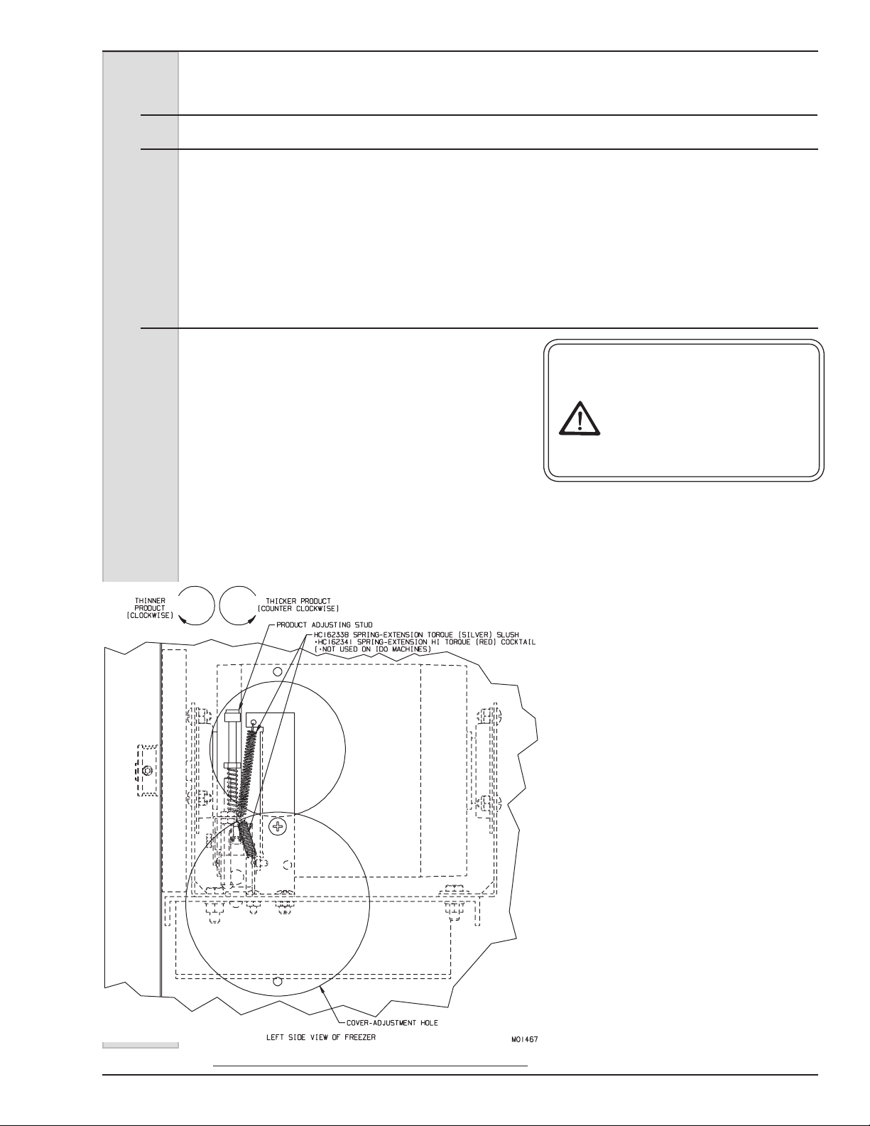
Figure 10-1 Attach Springs to Beater
4. Look into the access hole and you will
see an arm extending from the drive
motor (see gure 10-1.) The arm is
held in place by springs on both the
top and bottom. At the end of this
arm is a nylon (product) adjusting
stud. This stud is the only operating
adjustment on the freezer.
5. If the product is too thin, turn the
adjusting screw counterclockwise
(up) ½ turn. If the product is too thick,
turn the adjusting screw clockwise
(down) ½ turn. Close cover and
reconnect power. Turn selector
switch to “FREEZE” and wait until the
compressor has cycled off.
6. Recheck the product consistency
in 30 minutes. Repeat steps and
recheck until proper consistency is
obtained. Close cover.
For further information contact your
local Electro Freeze Distributor or the
Service Department of H. C. Duke &
Son, Inc. (309) 755-4553 or (800) 755-
4545.
184633 23
Page 34
ELECTRO FREEZE
Models 876, 876B, 876C, 876RH, 876BRH, 876CRH & 875 Batch
10.1 Refractometer/Brix Reading
A refractometer measures soluble sugar
content of mix, expressed in percentage
weight. This is normally referred to as a
“Brix Reading.” The typical refractometer
uses a scale from 0% to 32%.
Adjust the refractometer according to
the manufacturer’s instructions.
NOTE: A refractometer is a delicate
instrument and must be handled
with care. Never immerse the entire
refractometer in a cold drink. Cooling
the refractometer will cause it to give
inaccurate readings. A refractometer
cannot be used to read dietetic syrups.
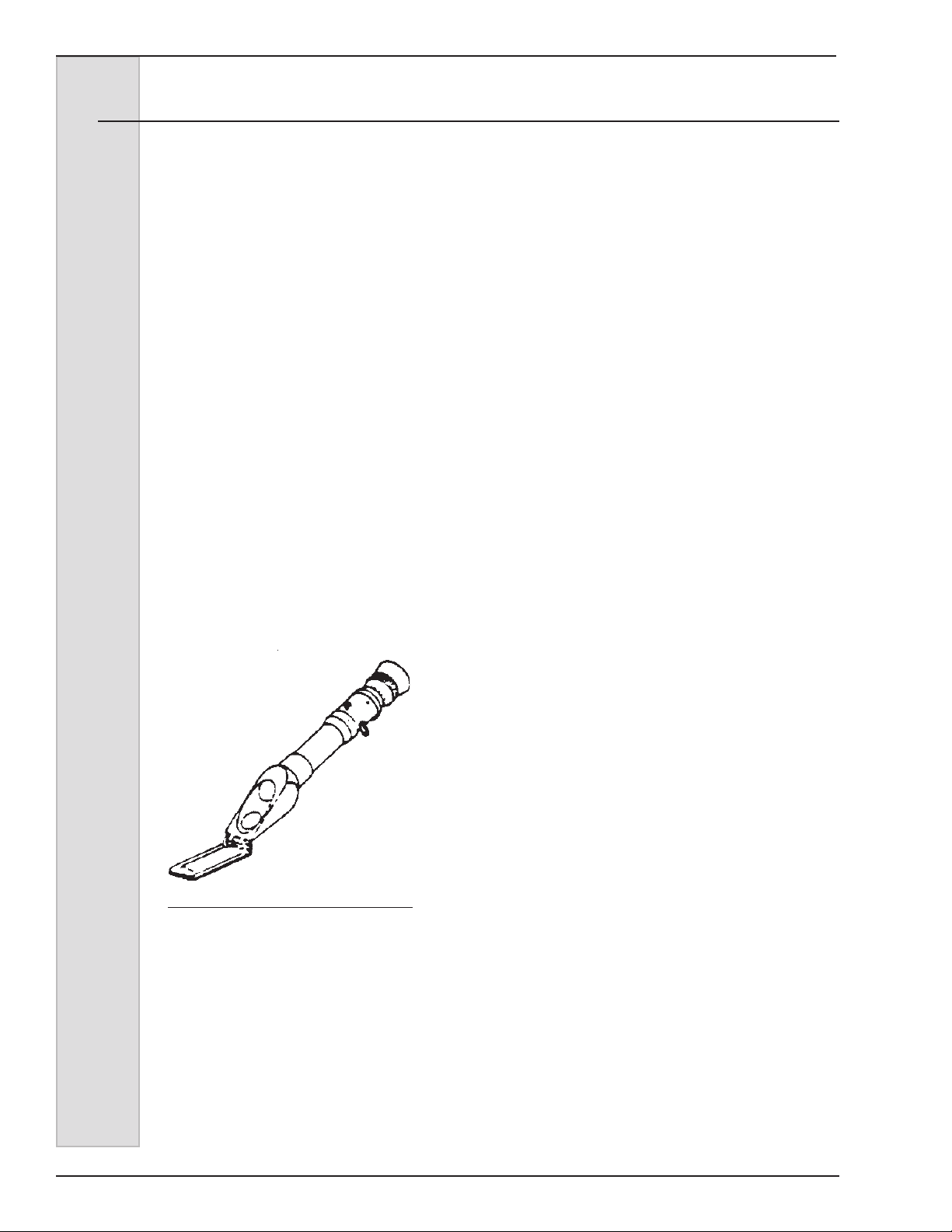
1. Open the hinged side of the
refractometer and place a few drops of
mix on the slide.
Close the slide and look through the eye
piece, holding the refractometer toward
the light. A line will appear across a
graduated scale which indicates the Brix
level.
Acceptable Brix level is 11-13 on a
refractometer.
NOTE: Never go below 11 on the Brix
Reading.
Some experimentation may be necessary
before correct Brix and serving
temperature will be found. Generally,
the higher the Brix reading the lower
the serving temperature. Conversely,
the lower the Brix reading, the higher
the required serving temperature. If the
complaint concerns product appearance,
(ie. too runny or too stiff) always rst
take a Brix reading of the mix because
variation in sugar content will have a
direct bearing on actual freezing point.
Figure 10-2 Refractometer
24 184633
Page 35
ELECTRO FREEZE
Models 876, 876B, 876C, 876RH, 876BRH, 876CRH & 875 Batch
11 Routine Maintenance
Electro Freeze recommends the following schedule to help maintain your equipment
in like-new operating condition, as well as to help protect your investment. Take the
time to learn and perform these routine procedures and receive in return many years of
valuable service from your freezer. Protect your investment!
This safety symbol
are uncertain about a procedure and its safety, or have any questions on the safety
precautions, contact your local Electro Freeze Distributor or H. C. Duke & Son, Inc.,
Electro Freeze Service Department for factory service assistance at (309) 755-4553 or
(800) 755-4545.
identies procedures that could cause personal injury. If you
DAILY
1. Wipe all exterior surfaces of the
freezer to remove any splattered mix.
NOTE: It is your responsibility to be
aware of and conform to the requirements
for meeting Federal, State and Local
Laws concerning the cleaning intervals
and cleaning and sanitizing procedures of
the freezer.
WEEKLY
1. Disassemble and thoroughly clean,
rinse, sanitize, air dry, reassemble
and sanitize all parts from this freezer
that come into contact with mix.
CAUTION
To prevent bacteria
growth, remove all
O-rings when cleaning.
Failure to do so could
create a health hazard.
2. Clean the cylinder and drain tube with
the appropriate brushes.
3. Upon cleaning, inspect and lubricate
all seals and O-rings as described that
come into contact with mix. Replace
as needed.
4. Carefully inspect all parts for wear,
including seals, O-rings, and blades.
Replace as required.
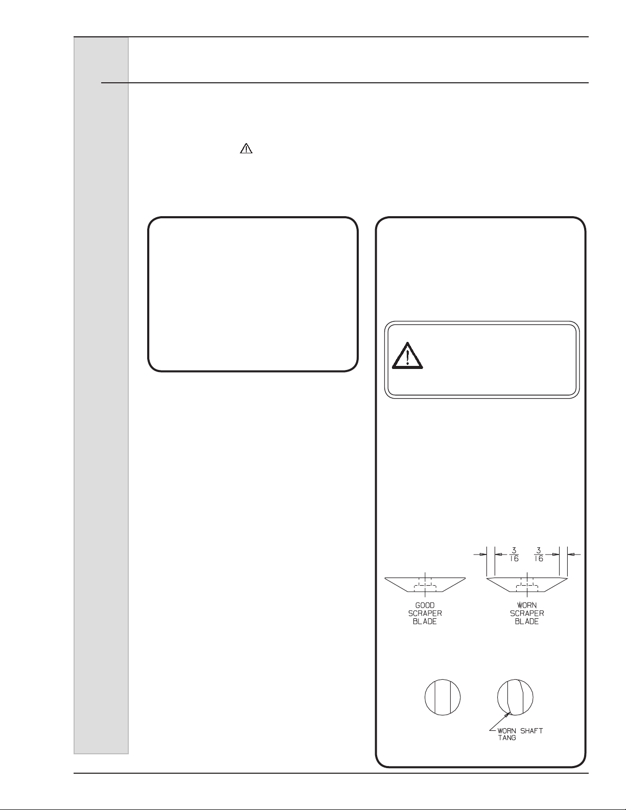
Replace blades if worn 3/16” or more.
5. Check the beater shaft tang and drive
quill for wear.
A worn drive quill will have a nonparallel
shape on the drive opening.
184633 25
Page 36
ELECTRO FREEZE
Models 876, 876B, 876C, 876RH, 876BRH, 876CRH & 875 Batch
12 Routine Maintenance (continued)
MONTHLY
CAUTION
To avoid electrical shock or
contact with moving parts,
make sure all switches are in
the “OFF” position and that
the main power supply is
disconnected.
1. Have air-cooled condenser ns
cleaned by qualied service
technician to remove all forms of dirt,
lint, and dust.
WARNING!
Failure to properly maintain/clean
your air condenser can cause
premature compressor failure.
Compressor failure due to improper
condenser care will void the
compressor warranty.
ANNUALLY
Contact your Electro Freeze Distributor to
perform the following services:
1. Inspect and clean the beater drive
motor.
2. Replace drive belt.
3. Clean the inside of the freezer
including base, side panels,
condenser, etc.
WEEKLY
To protect the unit during seasonal
shutdown, it is important to store the
freezer properly. Use the following
procedures:
1. Disconnect all power to the freezer.
2. Disassemble and wash all parts that
come into contact with the mix using
a warm, mild detergent solution.
Rinse in clear water and dry all parts
thoroughly.
3. Store the loose parts (i.e., the parts
in the head assembly and beater
assembly) in a safe, dry place.
4. Do not lay heavy objects on the
plastic or rubber parts.
5. Cover the freezer and all loose parts
to protect them from dust or other
elements that could contaminate
them while in storage. Place the
freezer in a dry location.
6. Have condenser ns on air-cooled
freezers cleaned.
Important:
Failure to purge the freezer of water
may result in severe damage to
the refrigeration system. Call your
Electro Freeze Distributor for more
information.
4. Check water-cooled condenser and
ush clean if necessary (water cooled
only).
5. Check fan condenser motors to see
if they have lubrication ports, if so
lubricate. (air cooled only)
6. Check the refrigeration system and
make any necessary adjustments.
USE ONLY ORIGINAL OR AUTHORIZED REPLACEMENT
PARTS WITH THIS FREEZER
(See Illustrated Replacement Parts Manual)
If you have any questions on items that are not included in this schedule or problems
where service assistance is needed, please call your local Electro Freeze Distributor
or H. C. Duke & Son, Inc. Electro Freeze Service Department for factory service
assistance at (309) 755-4553 or (800) 755-4545.
26 184633
7. If your freezer is water-cooled,
disconnect the water supply. Use
compressed air to blow out all
remaining water in the condenser.
8. When freezer is restarted after
seasonal shutdown, remember to
replace all o-rings and seal with new
parts. Rubber parts can lose their
elasticity and ability to seal when
they are stored.
Page 37
ELECTRO FREEZE
Models 876, 876B, 876C, 876RH, 876BRH, 876CRH & 875 Batch
13 Troubleshooting Tables
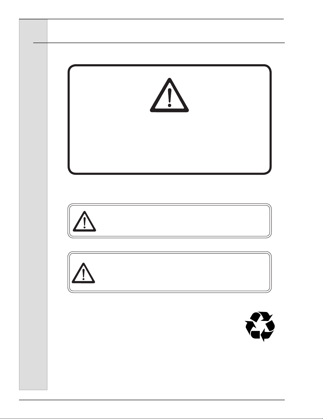
THIS SAFETY ALERT SYMBOL IDENTIFIES
IMPORTANT PERSONAL SAFETY MESSAGES IN
THIS MANUAL. WHEN YOU SEE THIS SYMBOL,
BE ALERT TO THE POSSIBILITY OF PERSONAL
INJURY. DO NOT ATTEMPT TO CONTINUE UNTIL
THE SAFETY PRECAUTIONS ARE THOROUGHLY
UNDERSTOOD.
SAFETY
CAUTION
All maintenance adjustments must be done by an
Electro Freeze Distributor or authorized service
technician.
CAUTION
To avoid electrical shock or contact with moving parts,
make sure all switches are in the “OFF” position and
that the main power supply is disconnected. Some
freezers have more than one disconnect switch.
Important:
Some refrigerants are hazardous to the earth’s atmosphere.
To protect our environment, use a refrigerant recovery/
recycling unit when removing refrigerant from the system.
42 184633
Page 38
ELECTRO FREEZE
Models 876, 876B, 876C, 876RH, 876BRH, 876CRH & 875 Batch
13 Troubleshooting Tables (continued)
PROBLEM PROBABLE CAUSE REMEDY
1. Freezer unplugged. 1. Plug in freezer.
Have service technician make
sure your freezer is connected to a
separate circuit independent from
any other electrical equipment.
2.
Have service technician check
fuse or breaker size and check for
low voltage; if not within 10% of
nameplate rating call the power
company.
Allow motor to cool off, reset
circuit breaker, and check product
consistency. See section 10.2,
Adjusting Product Consistency.
Freezer does
not operate.
Fuse or breaker blown at main
2.
disconnect.
3. Beater motor out on overload. 3.
Product will not
freeze.
4. Out on high pressure. 4.
5. Component failure. 5.
Improper mixing of product. Brix too
1.
high.
2. Component failure. 2.
3. Upper torque spring not connected. 3.
1.
Contact your Electro Freeze
Distributor for service.
Contact your Electro Freeze
Distributor for service.
Follow mixing instructions on product
label. See Section 10.1, Determining
Product Consistency.
Contact your Electro Freeze Distributor for service.
Install torque spring. See Section
10.2, Adjusting Product Consistency.
184633 43
Page 39
ELECTRO FREEZE
Models 876, 876B, 876C, 876RH, 876BRH, 876CRH & 875 Batch
13 Troubleshooting Tables (continued)
PROBLEM PROBABLE CAUSE REMEDY
Product too
thin.
Product too
thick.
Improper mixing of product. Brix too
1.
high.
2. Upper torque spring not connected. 2.
3. Adjustment screw not properly set. 3.
4. Component failure. 4.
Improper mixing of product. Brix too
1.
low.
2. Adjustment screw not properly set. 2.
3. Lower torque spring not connected. 3.
1.
1.
Follow mixing instructions on
product label. See section 10.2,
Adjusting Product Consistency.
Install torque spring. See
Section 10.2, Adjusting Product
Consistency.
Adjust screw to proper consistency
of product. See section 10.2,
Adjusting Product Consistency.
Contact your Electro Freeze
Distributor for service.
Follow mixing instructions on
product label. See Section 10.1,
Determining Product Consistency.
Adjust screw for proper consistency.
See Section 10.2, Adjusting Product
Consistency.
Install torque spring. See Section
10.2, Adjusting Product Consistency.
Leakage of
product from
drain tube.
Product
leaking around
head.
4. Component failure. 4.
Cup seal leaking or improperly
1.
installed.
2. Beater shaft assembly damaged. 2.
1. Head quad ring defective. 1. Replace quad ring.
2. Hand knobs not drawn up properly. 2.
Damaged or worn o-ring on the
3.
plunger assembly.
4. Damaged head assembly. 4.
Contact your Electro Freeze
Distributor for service.
Replace cup seal or install
1.
properly.
Contact your Electro Freeze
Distributor for service
Tighten hand knobs (hand tighten
only).
Replace and lubricate o-rings on
3.
plunger assembly.
Contact your Electro Freeze
Distributor for service
44 184633
Page 40
ELECTRO FREEZE
Models 876, 876B, 876C, 876RH, 876BRH, 876CRH & 875 Batch
13 Troubleshooting Tables (continued)
PROBLEM PROBABLE CAUSE REMEDY
Freezer
vibrates
Poor or slow
product
recovery.
1. Insufcient supply of mix. 1.
Improper mixing of product. Brix too
2.
low.
3. Worn blades. 3.
4. Freezer not level. 4.
5. Low on refrigerant. 5.
Dirty or blocked condenser, restricted
1.
air ow and/or high room temperature.
2. Dispensing too much product too fast. 2.
3. Product too warm going into freezer. 3.
2.
1.
Fill hopper at least 1/3 full – keep
hopper this full at all times.
Follow mixing instructions on product
label. See Section 10.2, Adjusting
Product Consistency.
Replace blades.
Level freezer.
Contact your Electro Freeze
Distributor for service
Remove obstruction and/or lower
room temperature. Have condenser
cleaned by your Electro Freeze
Distributor.
Check freezer capacity rating.
Precool – DO NOT FREEZE.
Product in
hopper freezes
Product
temperature in
hopper rises
above 45°F.
4. Component failure. 4.
Models 876RH and 876BRH Only
(Refrigerated Hopper-RH)
Component out of adjustment or
1.
component failure.
Product put in hopper was not
1.
precooled.
Component out of adjustment or
2.
component failure
1.
1.
2.
Contact your Electro Freeze
Distributor for service
Contact your Electro Freeze
Distributor for service
Precool product – DO NOT FREEZE.
Contact your Electro Freeze
Distributor for service.
184633 45
Page 41
ELECTRO FREEZE
Models 876, 876B, 876C, 876RH, 876BRH, 876CRH & 875 Batch
13 Troubleshooting Tables (continued)
PROBLEM PROBABLE CAUSE REMEDY
Check for other equipment on the
same circuit. Call power company
or your Electro Freeze Distributor.
Contact your Electro Freeze
Distributor for service
Contact your Electro Freeze
Distributor for service
Contact your Electro Freeze
Distributor for service
Check air condenser. If it needs to
be cleaned contact your Electro
Freeze Distributor.
Compressor
starts, but
remains in
start windings.
(single phase
only)
1. Low line voltage. 1.
2. Improperly wired. 2.
3. Current relay defective. 3.
4. Start capacitor weak. 4.
5. High discharge pressure. 5.
Contactor
chatters or
coil burned
out.
Head pressure
too low.
Head pressure
too high.
1. Low line voltage 1.
1. Shortage of refrigerant 1.
1. Refrigerant overcharge. 1.
2. Air in system. 2.
3. Dirty condenser (air cooled). 3.
4. Freezer location too warm. 4.
Contact your Electro Freeze
Distributor to check voltage. Check
for other equipment on the same
circuit.
Contact your Electro Freeze
Distributor for service
Contact your Electro Freeze
Distributor for service
Contact your Electro Freeze
Distributor for service
Have condenser cleaned by your
Electro Freeze Distributor.
Relocate freezer away from
restriction. Be sure nothing is placed
against the back of the freezer.
5. Restricted condenser (water cooled) 5.
6. Defective water valve. (water cooled) 6.
46 184633
Contact your Electro Freeze
Distributor for service
Contact your Electro Freeze
Distributor for service
Page 42
ELECTRO FREEZE
Models 876, 876B, 876C, 876RH, 876BRH, 876CRH & 875 Batch
13.1 MTS Troubleshooting Tables
PROBLEM PROBABLE CAUSE REMEDY
Unit operates
long or
continuously.
Noisy
Compressor.
1. Shortage of refrigerant. 1.
2. Dirty condenser. 2.
3. Moisture in system. 3.
4. Compressor failing. 4.
5. Using too much alcohol. 5.
6. Setting too cold. 6.
1. Tubing rattling. 1.
Motor off of internal springs. Springs
2.
broken or bent.
2.
Contact your Electro Freeze
Distributor for service.
Have condenser cleaned by your
Electro Freeze distributor.
Contact your Electro Freeze
Distributor for service.
Contact your Electro Freeze
Distributor for service.
Check formula and adjust. (No more
than 8% alcohol.)
Adjust warmer
Contact your Electro Freeze
Distributor for service.
Contact your Electro Freeze
Distributor for service.
Compressor
will not
start – hums
intermittently
(cycling on
overload).
Start
capacitors
burned out.
1. Improperly wired. 1.
2. Low line voltage. 2.
Open starting capacitor or current
3.
relay.
4. High discharge pressure. 4.
1. Voltage too low. 1.
2. Improper capacitor. 2.
3.
Contact your Electro Freeze
Distributor for service.
Contact your Electro Freeze
Distributor to check voltage. Check
for other equipment on the same
circuit.
Contact your Electro Freeze
Distributor for service.
Contact your Electro Freeze
Distributor for service.
Contact your Electro Freeze
Distributor to check voltage. Check
for other equipment on the same
circuit.
Contact your Electro Freeze
Distributor for service.
184633 47
Page 43

Keep your freezer in excellent
condition — always contact
your Electro Freeze Distributor
QUALITY PARTS
PROTECT
YOUR
for replacement parts and
maintenance scheduling.
NOTE: Contact your authorized Electro Freeze Distributor for instructions prior to warranty
compressor replacement.
INVESTMENT
Page 44

Page 45
REPLACEMENT PARTS MANUAL
with Illustrations
COCKTAIL AND
SLUSH FREEZERS
Models 876, 876B, 876C,
876RH, 876BRH, 876CRH
&
876B BATCH FREEZER
184633 — 5/16
H.C. Duke & Son, LLC. P/N 185235-01 May 2016 Printed In U.S.A.
Page 46

Page 47

ELECTRO FREEZE
Models 876, 876B, 876C, 876RH, 876BRH, 876CRH & 875 Batch
Replacement Parts Orders
You must have the serial number of your
freezer when ordering parts — parts may
differ with a particular serial number of the
same model.
Parts are listed using terminology that
best ts the function of the part. The
illustrations in this section will help you
to nd the correct part number and
description. The alphabetized parts
list can be used to verify part numbers
pertaining to the serial number of your
unit.
Place your parts order through your local
authorized Electro Freeze Distributor.
Name __________________________
Address: ________________________
_________________________
Phone: _________________________
For factory service assistance — contact
H. C. Duke & Son, LLC., Electro Freeze
Service Department as follows:
Phone: (309) 755-4553
(800) 755-4545
FAX: (309) 755-9858
E-mail: [email protected]
Table of Contents
Figure 1 Pull Valve Door Assembly ..............................1
Figure 2 Spigot Door Assembly (Optional) ..................2
Figure 3 Beater Shaft Assembly ...................................3
Figure 4 Electrical Box ..................................................4
Figure 6 Panels — Counter Models) .............................8
Figure 7 Panels — Floor Models (sheet 1 of 2) ............10
Figure 8 Water Cooled Assembly View .......................12
Figure 9 Water Cooled Assembly View ........................14
Figure 10 Air Cooled Assembly (Page 1 of 2) ................16
Figure 11 Drive Shaft and Bearing Assembly ................18
Figure 12 Consistency Control .......................................19
Figure 13 Motor and Bearing Assembly .........................20
Figure 13 Motor and Bearing Assembly .........................21
Accessories .....................................................22
Figure 14 Accessory - Merchandiser ..............................23
i
184633 iii
Page 48
ELECTRO FREEZE
Models 876, 876B, 876C, 876RH, 876BRH, 876CRH
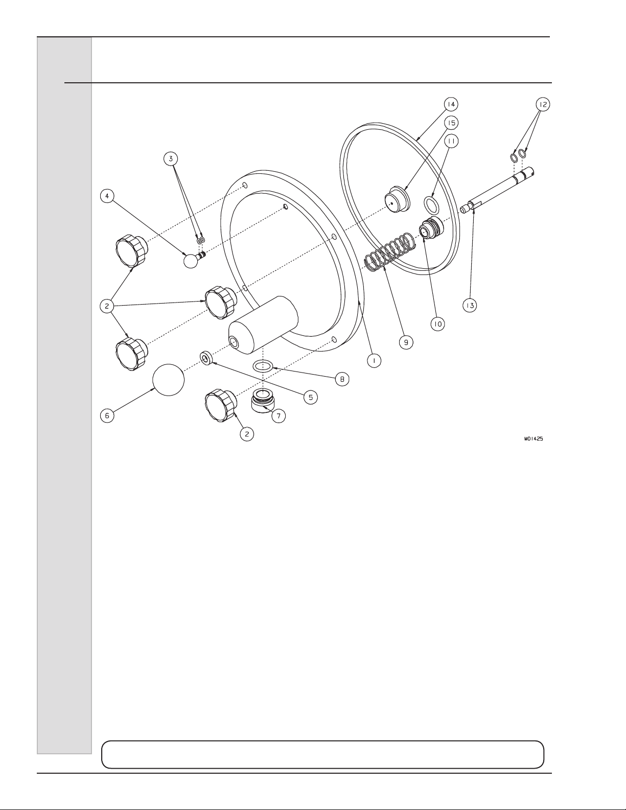
Figure 1 Pull Valve Door Assembly
Item Part No. Description
* HC114700 .............Door (Head) - Assy . Complete
1 ...............HC114989 .............Door (Head) - Assy . Pull Valve (Door Only)
2 ...............HC162633 ............Knob - Fluted T orque Blk 5/16-18 (Hand)
2A ............HC130194 ............Stud - Freezer Door
3 ...............HC160561 ............O-Ring (Plug)
...............HC115416 .............Plug - Assy . Air Bleed
4
5 ...............HC139274 ............Nut - Piston Rod
6 ...............HC162629 ............Knob - Ball 3/8-16 Thd Black
7 ...............HC136249-01 .......Outlet - Valve
8 ...............HC160582 ............O-Ring (Outlet - Valve)
9 ...............HC162319 ............Spring - Pull Valve
10 .............HC136253 ............Piston - V alve
11 .............HC160582 ............O-Ring (Piston)
12 .............HC160610 ............O-Ring (Rod)
13 .............HC113999 .............Rod - Assy. Piston
14 .............HC160606 ............Quad Ring
15 ............HC138336 ............Bushing - Plastic Door
* Includes parts listed above except items 2, 2A and 14.
Use only original or authorized replacement parts with this freezer.
Use of unapproved parts will void warranty.
Parts1 184297
Page 49

ELECTRO FREEZE
Models 876, 876B, 876C, 876RH, 876BRH, 876CRH
Figure 2 Spigot Door Assembly (Optional)
Item Part No. Description
*................HC114729 .............Door - Assy . Complete (Head)
1 ...............HC114990 .............Door(Only) - Assy . Spigot
2** ............HC162714 ............Body - Spigot
3** ............HC160647 ............O-Ring (Spigot)
4** ............HC162715 ............Plug - Spigot
............HC162713 ............Spring - Spigot
5**
6** ............HC162712 ............Cap - Plastic Spring
7** ............HC162711 .............Handle - Spigot
8** ............HC162710 ............Nut - Plastic
9 ...............HC162633 ............Knob - Fluted T orque Blk 5/16-18 (Hand)
9A ............HC130194 ............Stud - Freezer Door
10 .............HC115416 .............Plug - Assy . Air Bleed
11 .............HC160561 ............O-Ring (Plug)
12 .............HC138336 ............Bushing - Plastic Door
13 .............HC160606 ............Quad Ring
* Includes items 1, 10, 1 1, and 12
**Can be ordered together as:
HC162709 ............Spigot - Slush (Includes Items 2-8)
Use only original or authorized replacement parts with this freezer.
Use of unapproved parts will void warranty.
184297 Parts2
Page 50
ELECTRO FREEZE
Models 876, 876B, 876C, 876RH, 876BRH, 876CRH
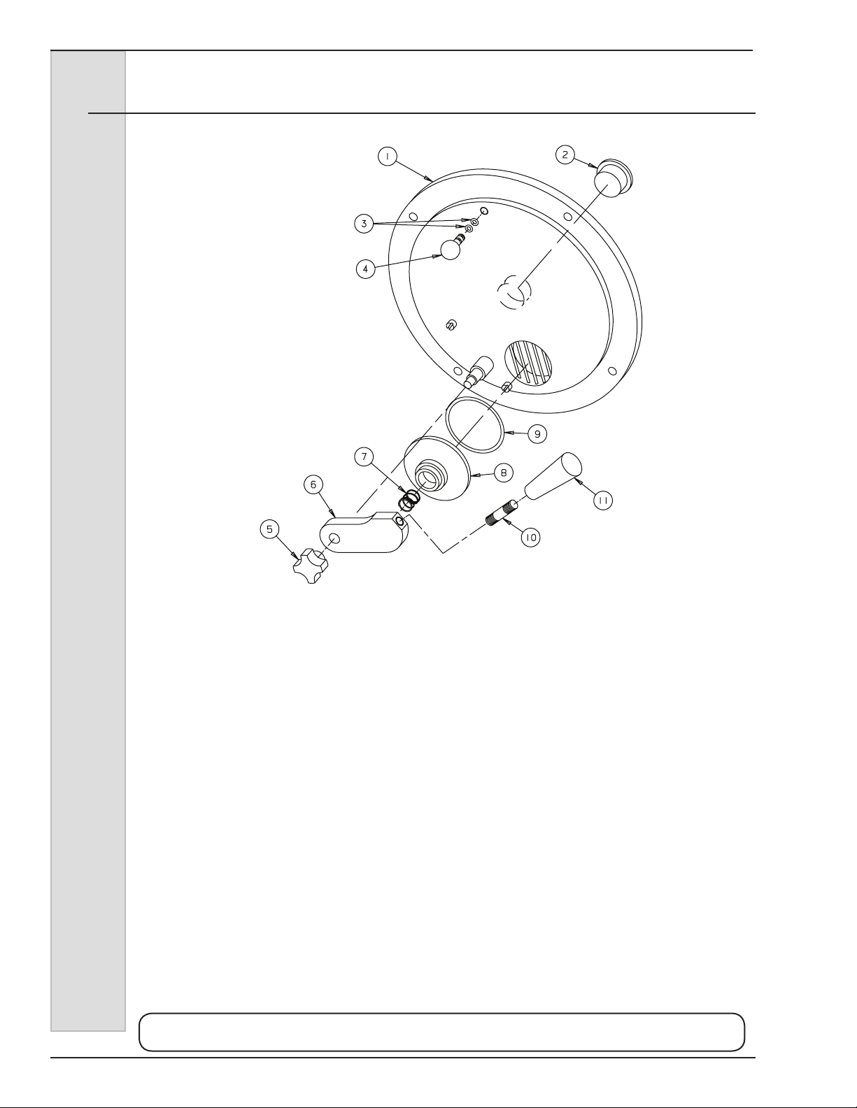
Figure 2 Batch Door Assembly (Optional)
Item Part No. Description
*................HC119044 .............Door - Assy . Batch Complete (Head)
1 ...............HC119043 .............Door(Only) - Assy . Batch
2 ...............HC138336 ............Bushing - Plastic Door
3 ...............HC160561 ............O-Ring (Plug)
4 ...............HC115416 .............Plug - Assy. Air Bleed
...............HC162622 ............Knob - Hand
5
6 ...............HC139933 ............Bar - Pivot Valve
7 ...............HC162345 ............Spring - Valve
8 ...............HC139932 ............Body - Pivot Valve
9 ...............HC160627 ............O-ring - Pivot Valve
10 .............HC139931 ............Rod - Handle
11 .............HC162626 ............Handle - Black Tapered
* Includes items 1-1 1
Use only original or authorized replacement parts with this freezer.
Use of unapproved parts will void warranty.
Parts3 184297
Page 51
ELECTRO FREEZE
Models 876, 876B, 876C, 876RH, 876BRH, 876CRH
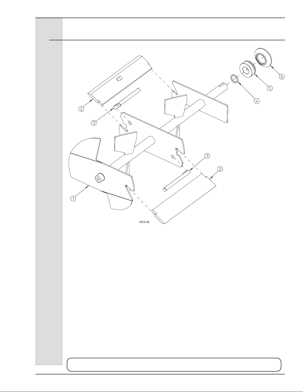
Figure 3 Beater Shaft Assembly
Item Part No. Description
1 ...............HC113072 .............Beater - Assy . Slush
or ..............HC119042 .............Beater - Assy. Batch
2 ...............HC138256 ............Blade - Scraper
3 ...............HC134649 ............Spring - Blade
4 ...............HC160605 ............Quad Ring
5* .............HC138215 ............Bushing (Washer) - Shaft Seal
6* .............HC160557 ............Seal - Beater Shaft
*Can be ordered together as:
HC116143 .............Seal - Assy . Shaft (Includes Items 5 & 6)
Use only original or authorized replacement parts with this freezer.
Use of unapproved parts will void warranty.
184297 Parts4
Page 52
ELECTRO FREEZE
Models 876, 876B, 876C, 876RH, 876BRH, 876CRH
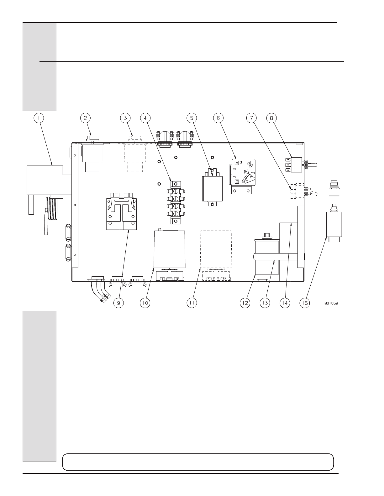
Figure 4 Electrical Box — Counter Model
(Page 1 of 2)
Use only original or authorized replacement parts with this freezer.
Use of unapproved parts will void warranty.
Parts5 184297
Page 53

ELECTRO FREEZE
Models 876, 876B, 876C, 876RH, 876BRH, 876CRH
Figure 4 Electrical Box — Counter Model
(Page 2 of 2)
Item Part No. Description
1 ............HC155425 ......... Cut - Out-High Pressure
2 ............HC161202 ......... Thermostat - 5° Fixed Diff. (876BRH, 876CRH)(Hopper)
3 ............HC161202 ......... Thermostat - 5° Fixed Diff. (876BRH, 876CRH)
(Units with Night Switch)
4 ............HC150795 ......... Strip - Terminal
5 ............HC150376 ......... Relay - Flange Base w/Cover (876BRH, 876CRH)
6 ............HC151427-01 .... Relay - Start/Run (Compressor)
7 ............HC150463 ......... Switch - Toggle (Units with Night Switch) (876BRH, 876CRH)
8 ............HC150465 ......... Switch - Toggle 3PDT CTR OFF (Selector) (876B, 876C)
or ...........HC150463 ......... Switch - Toggle DPDT CTR OFF (Selector) (876BRH, 876CRH)
8A ..........HC165023 ......... Nameplate - CLEAN/OFF/FREEZE
9 ............HC150339 ......... Contactor - 2 Pole 110v
or ...........HC150073 ......... Contactor - 2P 120V C25 (876B Batch Only)
10 ..........HC150263 ......... Timer - DOM/DOB Adj 120VAC
10 ..........HC150119 .........Socket - Octal Terminal
10A ........HC150120 ......... Clip - Retainer (Set of 2)
11 ...........HC150124 ......... Control - Liquid Level (Units w/Mix Indicator Light)
11 ...........HC150119 .........Socket - Octal Terminal
11A .........HC150120 ......... Clip - Retainer (Set of 2)
12 ..........HC151421 ......... Capacitor - Run (Compressor)
13 ..........HC160743 ......... Clamp - Hose 3-1/16 to 4
14 ..........HC151426-01 .... Capacitor - Start (Compressor)
15 ..........HC150452 ......... Breaker - Circuit 4.5 Amp
15A ........HC160160 ......... Washer - .385 x .750 x .031 Nylon
15B ........HC150440 ......... Seal - Reset Button
Use only original or authorized replacement parts with this freezer.
Use of unapproved parts will void warranty.
184297 Parts6
Page 54
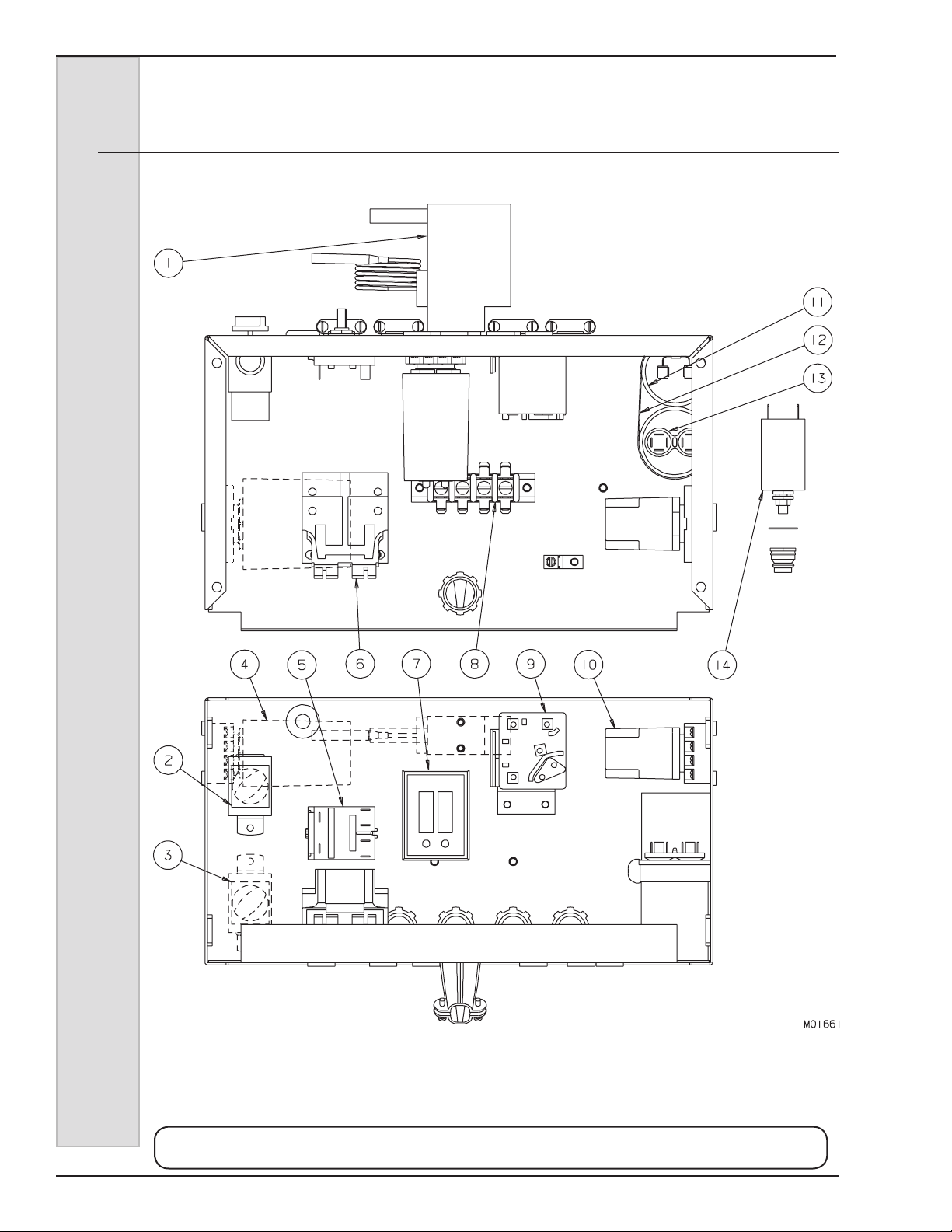
ELECTRO FREEZE
Models 876, 876B, 876C, 876RH, 876BRH, 876CRH
Figure 5 Electrical Box — Floor Models
(Page 1 of 2)
Use only original or authorized replacement parts with this freezer.
Use of unapproved parts will void warranty.
Parts7 184297
Page 55

ELECTRO FREEZE
Models 876, 876B, 876C, 876RH, 876BRH, 876CRH
Figure 5 Electrical Box — Floor Models
(Page 2 of 2)
Item Part No. Description
1 ............HC155425 ......... Cut Out - High Pressure
2 ............HC161202 ......... Thermostat - 5° Fixed Diff. Cylinder (876RH)
......................................... (Units w/Night Switch)
3 ............HC161202 ......... Thermostat - 5° Fixed Diff. Hopper (876RH)
4 ............HC150124 ......... Control - Liquid Level (Units w/Mix Indicator Light)
4A ..........HC150119 .........Socket - Octal Terminal
4B ..........HC150120 ......... Clip - Retainer (Set of 2)
5 ............HC115816 .........Kit - Rotary Switch Replacement (w/o Night Switch)
5A ..........HC150462 ......... Knob - Rotary Switch
5B ..........HC165022 ......... Nameplate - CLEAN/OFF/FREEZE
5C ..........HC150786 ......... Bushing - Snap
5D ..........HC134653 ......... Extension - Switch (Shaft)
5E ..........HC150460 ......... Coupler - Switch to Shaft Extension
or ...........HC150465 ......... Switch - Toggle (Clean/Off/Freeze) (876RH Units w/Night Switch)
HC165023 ......... Nameplate - CLEAN/OFF/FREEZE (Units w/Night Switch)
6 ............HC150339 ......... Contactor - 2 Pole 110V
7 ............HC150263 ......... Timer - DOB/DOM Adj 120VAC
8 ............HC150795 ......... Strip - Terminal
9 ............HC151427-01 .... Relay - Start/Run (Compressor)
10 ..........HC150384 ......... Relay - DPDT 120v (876RH)
10A ........HC150119 .........Socket - Octal Terminal
10B ........HC150120 ......... Clip - Retainer (Set of 2)
11 ...........HC151426-01 .... Capacitor - Start (Compressor)
12 ..........HC160743 ......... Clamp - Hose 3-1/6 to 4
13 ..........HC151421 ......... Capacitor - Run (Compressor)
14 ..........HC150452 ......... Breaker - Circuit - 4.5 Amp.
14A ........HC160160 ......... Washer - .385 x .750 x .031 Nylon
14B ........HC150440 ......... Seal - Reset Button
Not Shown:
HC150466 ......... Switch - Toggle SPDT (Day/Night)
(876RH w/Night Switch & Mix Indicator)
Use only original or authorized replacement parts with this freezer.
Use of unapproved parts will void warranty.
184297 Parts8
Page 56

ELECTRO FREEZE
Models 876, 876B, 876C, 876RH, 876BRH, 876CRH
Figure 6 Panels — Counter Models
(Page 1 of 2)
Use only original or authorized replacement parts with this freezer.
Use of unapproved parts will void warranty.
Parts9 184297
Page 57
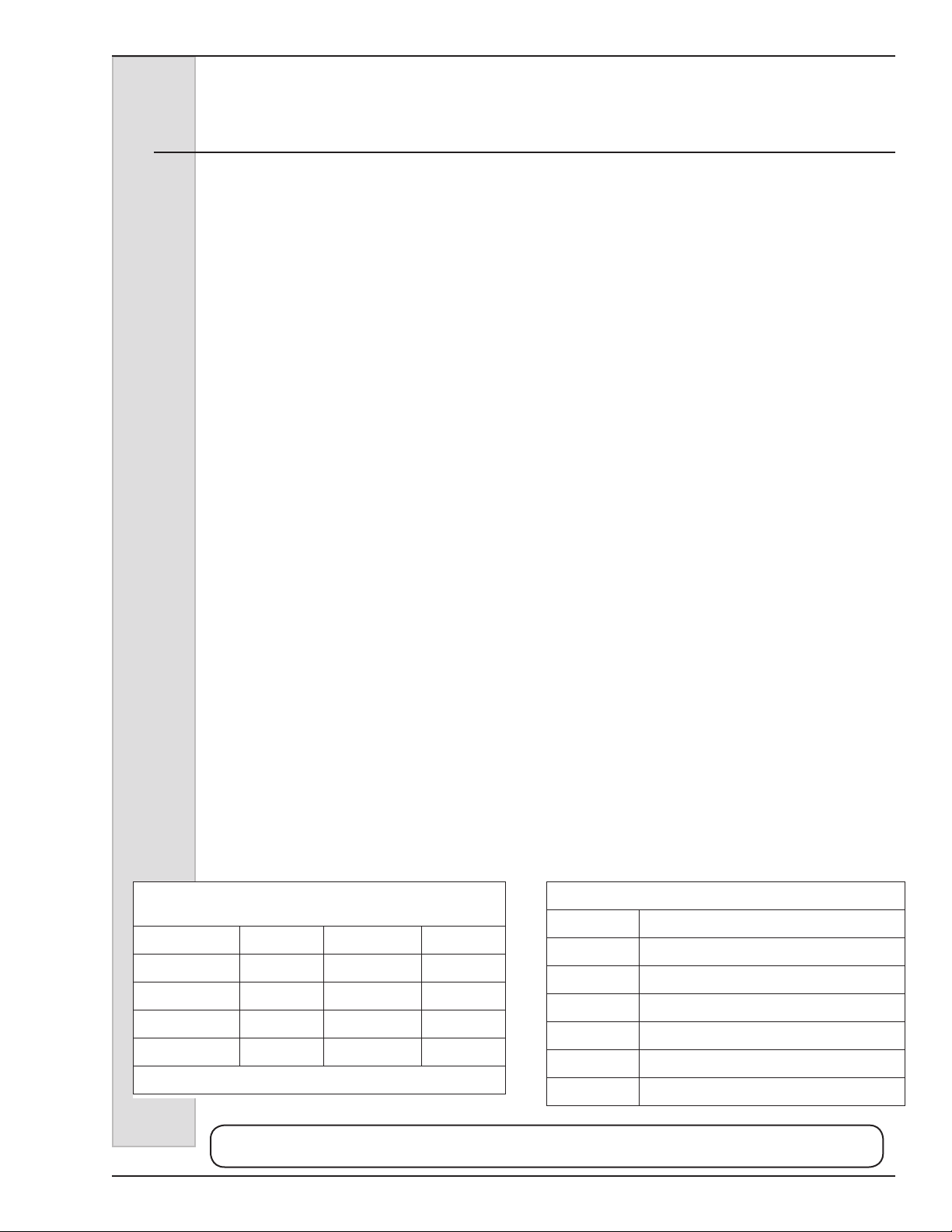
ELECTRO FREEZE
Models 876, 876B, 876C, 876RH, 876BRH, 876CRH
Figure 6 Panels — Counter Models
(Page 2 of 2)
Item Part No. Description
1 ............HC116928-C .....Panel - Assy. Front
HC116929-C ..... Panel - Assy. Front (with Optional Mix Light)
HC119090 ......... Panel - Assy. Front (876B-Batch)
2 ............HC118616 .........Kit - 4-inch Adjustable Leg w/Antislip Pad (Set of 4) includes
HC162114 ....Leg - Four Inch Adjustable
HC162130 ...Pad - Foot Anti Slip
3 ............HC135802 ......... Pan - Drip
HC116088 ......... Tray - Assy. Drip & Flavor (4 Bottle, w/Self Serve Decal
and w/o Bottles & Insert)
HC117529 ......... Tray - Assy. Drip & Flavor (4 Bottle, w/Tray and
w/o Decal, Bottles & Insert)
HC139950 ......... Panel - Shelf (876B-Batch)
4 ............HC135803 ......... Insert - Drip Pan
5 ............HC196121 ......... Cover - Hopper
..............HC118691 .........Cover - Assy. Hopper Insulate (Optional RH Models)
6 ............HC116067-C .....Panel - Assy. Hopper & Top (876B, 876B-Batch, 876C)
HC115913-C ..... Panel - Assy. Hopper & Top (876BRH, 876CRH)
7 ............HC138664-C ..... Panel - Side RH*
8 ............HC136966-C ..... Panel - Side LH*
9 ............HC159064 ......... Grommet - 7/8 OD x 5/8 ID (Drain Tube)
10 ..........HC136959 ......... Cover - Adjustment Hole
10A ........HC160076 ......... Screw - TRPM #10-24 x 1/2 SST
11 ...........HC138736 ......... Panel - Rear (Water Cooled)
HC138749 ......... Panel - Rear (Air Cooled)
12 ..........HC165414 ......... Nameplate - Electro Freeze
13 ..........HC150546 ......... Light - Indicator 125V (Optional)
14 ..........HC165023 ......... Nameplate - CL/OFF/FR Toggle Switch
* Left or right hand is determined as you face the front of the freezer.
Hardware for 876 Series
Counter Model Panels
Panel Screw Nut-Speed Space
Front HC160048 HC160117 HC163103
Rear/Corners HC160048 HC160117 n/a
Side HC160028 HC160387 HC138455
Drip Tray HC160049 n/a HC163103
*N/A - Not Applicable
Use only original or authorized replacement parts with this freezer.
Use of unapproved parts will void warranty.
184297 Parts10
Part No. Description
HC165025 Beater Warning
HC165065 Cleaning Instructions (RH Models)
HC165091 Clear Overlay
HC165126 Panel Removal
Hc165151 Trimstrip (RH Models)
HC169052 Ventilation 3 in.
Panel Decals & Labels
Page 58
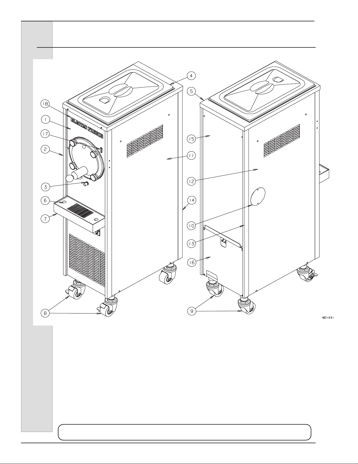
ELECTRO FREEZE
Models 876, 876B, 876C, 876RH, 876BRH, 876CRH
Figure 7 Panels — Floor Models (sheet 1 of 2)
Use only original or authorized replacement parts with this freezer.
Use of unapproved parts will void warranty.
Parts11 184297
Page 59

ELECTRO FREEZE
Models 876, 876B, 876C, 876RH, 876BRH, 876CRH
Figure 7 Panels — Floor Models (sheet 2 of 2)
Item Part No. Description
1 ............HC113836-C .....Panel - Assy. Upper Front
HC116925 ......... Panel - Assy. Upper Front (876RH w/Night Switch & Mix Indicator)
HC116926 ......... Panel - Assy. Upper Front (876RH w/Night Switch)
2 ............HC113835-C .....Panel - Assy. Lower Front
3 ............HC159064 ......... Grommet - 7/8 OD x 5/8 ID (Drain Tube)
4 ............HC196121 ......... Cover - Hopper
HC118691 ......... Cover - Assy. Hopper Insulate (Optional 876RH)
5 ............HC116066-C .....Panel - Assy. Hopper & Top (876)
HC116075-C ..... Panel - Assy. Hopper & Top (876RH)
6 ............HC136064 ......... Insert - Drip Pan
HC138174 ......... Insert - Drip Pan (876RH w/Ill. Sign & Bottle Rack)
7 ............HC136065 ......... Pan -Drip
HC117529 ......... Tray - Assy. Drip & Flavor (876RH w/Ill. Sign & Bottle Rack)
8 ............HC162133 ......... Caster - Low Prole with Brake
8A ..........HC150736 ......... Nut - Lock Conduit 1-1/4
9 ............HC162134 ......... Caster - Low Prole w/o Brake
9A ..........HC150736 ......... Nut - Lock Conduit 1-1/4
10 ..........HC163959 ......... Cover - Adjustment Hole
10A ........HC160076 ......... Screw - TRPM #10-24 x 1/2 SST
11 ...........HC136964-C ..... Panel - Side RH*
12 ..........HC136963-C ..... Panel - Side LH*
13 ..........HC136960-C ..... Post - Rear Corner LH*
14 ..........HC136961-C ..... Post - Rear Corner RH*
15 ..........HC136962-C ..... Panel - Rear
16 ..........HC139398 ......... Panel - Lower Rear (Water Cooled)
17 ..........HC150546 ......... Light - Indicator 125V Vertical(Units with mix indicator light)
18 ..........HC165414 ......... Nameplate - Electro Freeze Large
Not Shown:
HC112978 ......... Leg - Assy. 6-inch (Optional)
* Left or right hand is determined as you face the front of the freezer.
Hardware for 876 Series
Floor Model Panels
Panel Screw Nut-Speed Space
Front HC160048 HC160117 HC163103
Rear/Corners HC160048 HC160117 n/a
Side HC160028 HC160387 HC138455
Drip Tray HC160049 n/a HC163103
*N/A - Not Applicable
Use only original or authorized replacement parts with this freezer.
Use of unapproved parts will void warranty.
Panel Decals & Labels
Part No. Description
HC165025 Beater Warning
HC165065 Cleaning Instructions (876RH)
HC165091 Clear Overlay
HC165126 Panel Removal
HC165151 Trimstrip (876RH)
HC169052 Ventilation 3 in.
184297 Parts12
Page 60
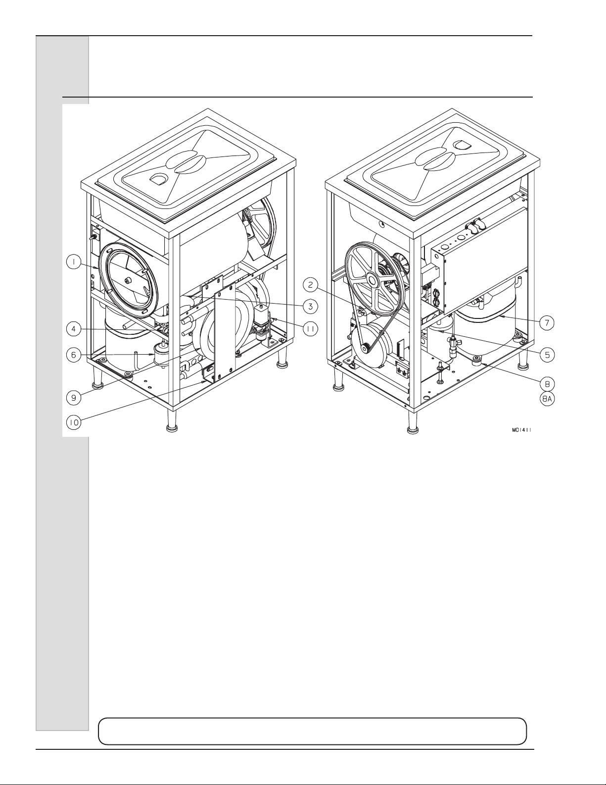
ELECTRO FREEZE
Models 876, 876B, 876C, 876RH, 876BRH, 876CRH
Figure 8 Water Cooled Assembly View
— Counter Model (Page 1 of 2)
Use only original or authorized replacement parts with this freezer.
Use of unapproved parts will void warranty.
Parts13 184297
Page 61

ELECTRO FREEZE
Models 876, 876B, 876C, 876RH, 876BRH, 876CRH
Figure 8 Water Cooled Assembly View
— Counter Model (Page 2 of 2)
Item Part No. Description
1 ............HC115916 .........Cylinder - Assy. Evaporator (876, 876B, 876C)
HC116332 ......... Cylinder - Assy. Evaporator (RH Models)
2 ............HC155453 ......... Valve - Auto Expansion Sweat (Cylinder)
3 ............HC113087 .........Exchanger - Assy. Heat
4 ............HC155459 ......... Glass - Sight
5 ............HC155060 ......... Receiver - 2 1lb. 1/4 Sweat
6 ............HC155063 ......... Drier - Filter 3 cu in Sweat
7 ............HC116824 .........Compressor - Assy. 115-1-60 includes
HC151421 .........Capacitor - Run
HC151426-01 ....Capacitor - Start
HC155063 .........Drier - Filter 3 cu in Sweat
HC151427-01 ....Relay - Start
8 ............HC151431 ......... Grommet - Compressor Mounting
8A ..........HC151432 ......... Sleeve - Compressor Mounting
9 ............HC155029 ......... Condenser - Water
10 ..........HC119021 .........Bracket - Assy. Condenser Mtg.
11 ...........HC112080 .........Valve - Assy. Water includes
HC155410 .........Valve - Water
11A .........HC155444 ......... Kit - Water Valve
Not Shown:
HC115923 ......... Tube - Assy. Drain
HC155419 ......... V alve - Access
HC155435 ......... Valve - Solenoid (RH Models)
HC155452 ......... Valve - Automatic Expansion Sweat (RH Models)
Use only original or authorized replacement parts with this freezer.
Use of unapproved parts will void warranty.
184297 Parts14
Page 62
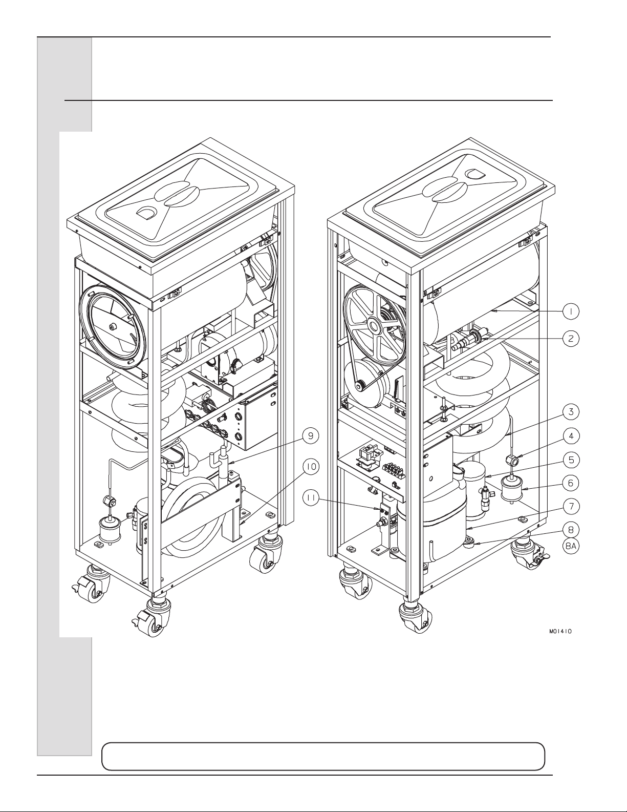
ELECTRO FREEZE
Models 876, 876B, 876C, 876RH, 876BRH, 876CRH
Figure 9 Water Cooled Assembly View
— Floor Models (Page 1 of 2)
Use only original or authorized replacement parts with this freezer.
Use of unapproved parts will void warranty.
Parts15 184297
Page 63

ELECTRO FREEZE
Models 876, 876B, 876C, 876RH, 876BRH, 876CRH
Figure 9 Water Cooled Assembly View
— Floor Models (Page 2 of 2)
Item Part No. Description
1 ............HC115916 .........Cylinder - Assy. Evaporator (876, 876B, 876C))
HC116332 ......... Cylinder - Assy. Evaporator (RH Models)
2 ............HC155453 ......... Valve - Auto Expansion Sweat (Cylinder)
3 ............HC112870 .........Exchanger - Assy. Heat
4 ............HC155459 ......... Glass - Sight
5 ............HC155060 ......... Receiver - 2 1lb. 1/4 Sweat
6 ............HC155063 ......... Drier - Filter 3 cu in Sweat
7 ............HC116824 .........Compressor - Assy. 115-1-60 includes
HC151421 .........Capacitor - Run
HC151426-01 ....Capacitor - Start
HC155063 .........Drier - Filter 3 cu in Sweat
HC151427-01 ....Relay - Start
8 ............HC151431 ......... Grommet - Compressor Mounting
8A ..........HC151432 ......... Sleeve - Compressor Mounting
9 ............HC155029 ......... Condenser - Water
10 ..........HC139813 ......... Bracket - Water Condenser
11 ...........HC112080 .........Valve - Assy. Water includes
HC155410 ...Valve - Water
11A .........HC155444 ......... Kit - Water Valve
Not Shown:
HC115923 ......... Tube - Assy. Drain
HC155452 ......... Valve - Auto Expansion (Hopper) (RH Models)
HC155435 ......... Valve - Solenoid (RH Models)
Use only original or authorized replacement parts with this freezer.
Use of unapproved parts will void warranty.
184297 Parts16
Page 64

ELECTRO FREEZE
Models 876, 876B, 876C, 876RH, 876BRH, 876CRH
Figure 10 Air Cooled Assembly (Page 1 of 2)
Use only original or authorized replacement parts with this freezer.
Use of unapproved parts will void warranty.
Parts17 184297
Page 65

ELECTRO FREEZE
Models 876, 876B, 876C, 876RH, 876BRH, 876CRH
Figure 10 Air Cooled Assembly (Page 2 of 2)
Item Part No. Description
* .............HC116869 .........Condensing Unit - Assy 3/4 HP 115/1/60
1 ............HC116870 .........Plate - Assy. Condensing Base
2 ............HC116824 .........Compressor - Assy. 115-1-60 includes
HC151421 .........Capacitor - Run
HC151426-01 ....Capacitor - Start
HC155063 .........Drier - Filter 3 cu in Sweat
HC151427-01 ....Relay - Start
3 ............HC116871 .........Condenser - Assy. Air includes
HC138668 .........Shroud - Condenser
HC155126-01-C Condenser - Air Ried
4 ............HC116868 .........Fan - Assy. Condenser includes
HC151074-01 ....Motor - Fan 35w 115V 60 Hz
HC159020 .........Blade - Fan 11 in 26°
HC137632 .........Bracket - Fan Condenser
5 ............HC155060 ......... Receiver - 2 1lb. 1/4 Sweat
6 ............HC137809 ......... Support - Connector Compressor
7 ............HC150705 ......... Connector - 3/8x 90°
8 ............HC160740 ......... Clamp - Tube 1/4
9 ............HC155063 ......... Drier - Filter 3 cu in Sweat
10 ..........HC155459 ......... Glass - Sight
11 ...........HC155419 ......... Valve - Access
12 ..........HC155536 ......... Tee - 1/2 x 1/2 x 1/2 SWT WROT
13 ..........HC151431 ......... Grommet - Compressor Mounting
14 ..........HC151432 ......... Sleeve - Compressor Mounting
15 ..........HC160347 ......... Screw - HXHC 5/16-18 x 1-3/8 ZN
16 ..........HC160130 ......... Washer - Flat 1/4 ZN
17 ..........HC159950 ......... Screw - HXSF 1/4-20 x 1/2 ZN
18 ..........HC160151 ......... Washer - Ext Tooth 1/4 ZN
19 ..........HC155529 ......... Tee - 1/4 x 1/4 x 1/4 SOL CU
20 ..........HC160453 ......... Nut - Hex 3/8-16 ZN
21 ..........HC160154 ......... Washer - Ext Tooth 3/8 ZN
* Includes all of items above.
Not Shown:
HC115916 ......... Cylinder - Assy. Evaporator (876, 876B, 87C))
HC116332 ......... Cylinder - Assy. Evaporator (876RH, 876BRH, 876CRH)
HC155453 ......... Valve - Auto Expansion Sweat (Cylinder)
HC113087 ......... Exchanger - Assy. Heat (Counter Models)
HC112870 ......... Exchanger - Assy. Heat (Floor Models)
HC115923 ......... Tube - Assy. Drain
HC155452 ......... Valve - Auto Expansion Sweat (Hopper) (876RH)
HC155435 ......... Valve - Solenoid (876RH)
Use only original or authorized replacement parts with this freezer.
Use of unapproved parts will void warranty.
184297 Parts18
Page 66
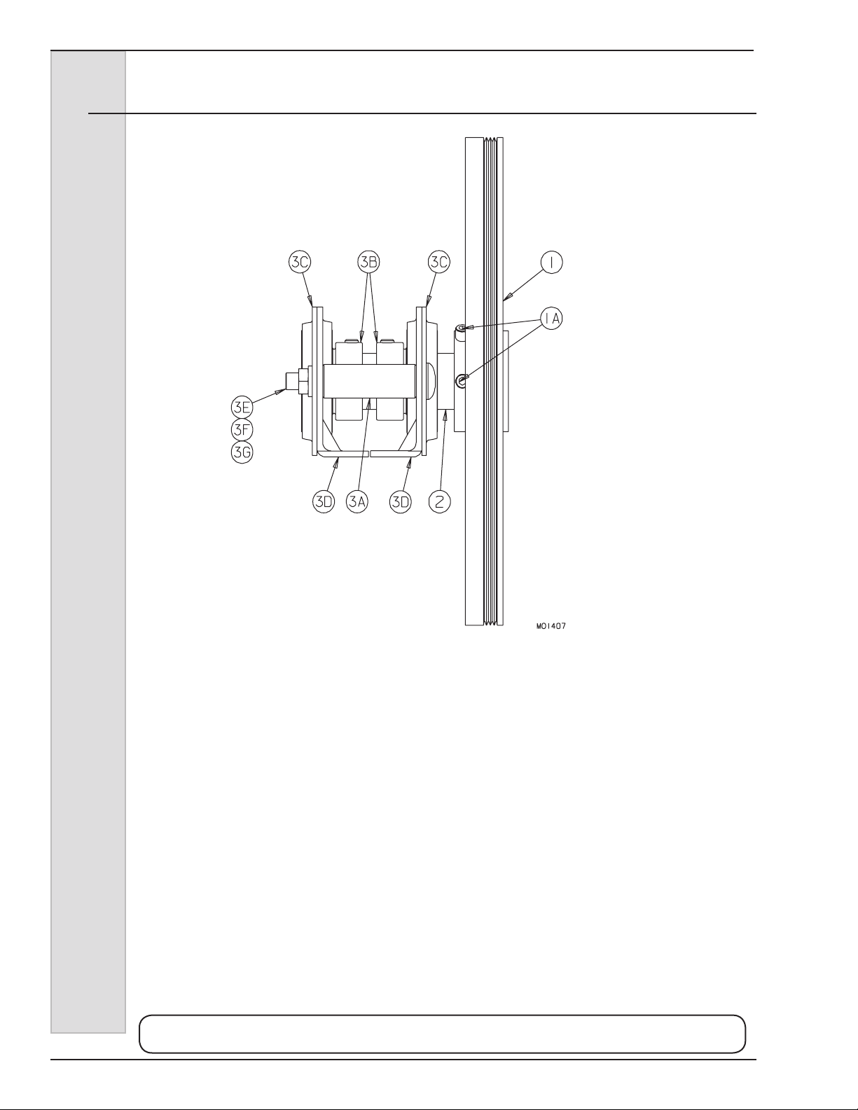
ELECTRO FREEZE
Models 876, 876B, 876C, 876RH, 876BRH, 876CRH
Figure 11 Drive Shaft and Bearing Assembly
Item Part No. Description
HC112843 ......... Bearing - Assy. Complete Rear (includes HC112844 & HC112862)
HC112844 ......... Sheave - Assy. Driven & Quill (includes 1, 1A, 2)
1 ............HC153615 ......... Sheave - Driven
1A ..........HC160033 ......... Screw - SK Set 5/16-18 x 3/8 BKOX
2 ............HC112842 .........Quill - Assy. Drive w/ Key
3 ............HC112862 .........Bearing - Assy. Rear includes
3A ..........HC130189 ......... Spacer - Rear Bearing
3B ..........HC153013 ......... Bearing - Drive Quill (w/Lock ring)
3C ..........HC153127 ......... Plate - Retainer, Bearing
3D ..........HC153128 ......... Stamping - Bearing Base
3E ..........HC160143 ......... Washer - Lock 3/8 ZN
3F ..........HC160407 ......... Bolt - Carriage 3/8-16 x 3-1/4 ZN
3G ..........HC160453 ......... Nut - Hex 3/8-16 ZN
Not Shown:
HC115681 ......... Bar - Alignment (Loaner) (used to align bearings to cylinder)
HC115681-01 .... Bar - Alignment (Purchase)
Use only original or authorized replacement parts with this freezer.
Use of unapproved parts will void warranty.
Parts19 184297
Page 67

ELECTRO FREEZE
Models 876, 876B, 876C, 876RH, 876BRH, 876CRH
Figure 12 Consistency Control
Item Part No. Description
1 ............HC117492 .........Switch - Assy. Torque includes
HC150457 ...Switch - Torque Control
HC135003 ...Cover - Switch Top
HC135004 ...Cover - Switch Bottom
2 ............HC159999 ......... Screw - RDHM #8-32 (Stop)
3 ............HC162118 .........Bumper - Button (Rubber)
............HC116414 .........Arm - Assy.Torque
4
5 ............HC160102 ......... Nut - HEX #8-32 (Stop)
6 ............HC139544 ......... Stud - Adjusting
6A ..........HC160138 ......... Washer - Flat #10 (Adjusting Stud)
7 ............HC160092 ......... Nut - Cap #10-32 Nylon
8 ............HC160344 ......... Nut - Hex #10-32 ZN
9 ............HC162346 ......... Spring - Adjusting Screw
10 ..........HC134632 ......... Bracket - Switch Mtg.
11 ...........HC136959 ......... Cover - Adjustment Hole
12 ..........HC162338 ......... Spring - Extension Torque-Slush (Silver)
13 ..........HC160076 ......... Screw - TRPM #10-24 x 1/2 SST (Cover-Adjustment Hole)
14 ..........HC162338 ......... Spring - Extension Torque-Slush (Silver)
15 ..........HC134661 ......... Bracket - Spring Torque Control
Use only original or authorized replacement parts with this freezer.
Use of unapproved parts will void warranty.
184297 Parts20
Page 68
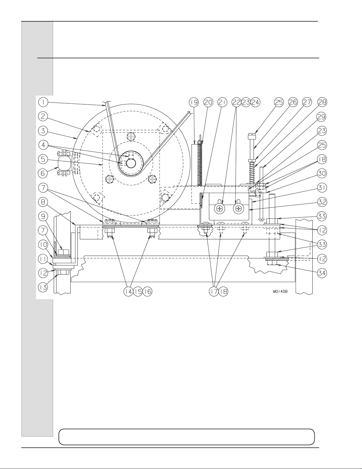
ELECTRO FREEZE
Models 876, 876B, 876C, 876RH, 876BRH, 876CRH
Figure 13 Motor and Bearing Assembly
(Page 1 of 2)
Use only original or authorized replacement parts with this freezer.
Use of unapproved parts will void warranty.
21 184297
Page 69

ELECTRO FREEZE
Models 876, 876B, 876C, 876RH, 876BRH, 876CRH
Figure 13 Motor and Bearing Assembly
(Page 2 of 2)
Item Part No. Description
1 ............HC153139 ......... Belt - Poly V (Counter)
HC153125 ......... Belt - Poly V (Floor)
2 ............HC116585* ........Kit - FE Slush Motor Replacement (Counter)
or ...........HC116584* ........Kit - FE Slush Motor Replacement (Floor)
3 ............HC153610 ......... Flywheel - Driver Sheave
4 ............HC160495 ......... Screw - SK Set
5 ............HC115790 .........Bearing - Assy. Retainer (Front) includes
HC153027 .........Bearing - Motor Mount
HC134659 .........Bracket - Motor Mount
5A ..........HC115791 .........Bearing - Assy. Retainer (Rear) includes
HC153027 ...Bearing - Motor Mount
HC134904 ...Bracket - Motor Mount
6 ............HC150705 ......... Connector - 3/8 x 90°
6A ..........HC150665 ......... Conduit - 1/2 Thinwall Extraex
7 ............HC160130 ......... Washer - Flat 1/4 ZN
8 ............HC138717 ......... Plate - Motor
9 ............HC159220 ......... Nut - Lock 5/16-18 ZN
10 ..........HC199012 ......... Washer - Rubber
11 ...........HC162562 ......... Spacer - Rubber
12 ..........HC160131 ......... Washer - Flat 5/16 ZN
13 ..........HC160009 ......... Screw - HXHC 5/16-18 x 1 ZN
14 ..........HC160021 ......... Screw - HXHC 1/4–20 x 3/4 ZN
15 ..........HC160104 ......... Nut - Hex 1/4–20 ZN
16 ..........HC160141 ......... Washer - Lock 1/4 ZN
17 ..........HC160049 ......... Screw - TRPM #8-32 x 1/ SST
18 ..........HC160102 ......... Nut - HEX #8-32 ZN
19 ..........HC134661 ......... Bracket - Spring Torque
20 ..........HC162338 ......... Spring - Extension Torque
21 ..........HC162341 ......... Spring - Extension Hi Torque
22 ..........HC160156 ......... Screw - TRHM #6-32 x 1-1/4 SST
23 ..........HC160138 ......... Washer - Flat #10 ZN
24 ..........HC160309 ......... Nut - Hex #6-32 ZN
25 ..........HC160092 ......... Nut - Cap #10-32 Nylon
26 ..........HC139544 ......... Stud - Adjusting
27 ..........HC160344 ......... Nut - Hex #10-32 ZN
28 ..........HC162346 ......... Spring - Adjusting Screw
29 ..........HC159999 ......... Screw - RDHM #8-32 x 3/4 ZN
30 ..........HC116414 .........Arm - Assy. Torque
31 ..........HC134632 ......... Bracket - Switch Mounting
32 ..........HC117492 .........Switch - Assy Torque includes
HC135004 .........Cover - Switch Bottom
HC135003 .........Cover - Switch Top
HC150457 .........Switch - Torque Control
33 ..........HC160105 ......... Nut - Motor Assembly 5/16-18 ZN
34 ..........HC160036 ......... Screw - HXHC 5/16-18 x 3-1/2
* Includes Motor & Bearing Assembly, Circuit Breaker, and Reset Button Seal.
Use only original or authorized replacement parts with this freezer.
Use of unapproved parts will void warranty.
184297 22
Page 70

ELECTRO FREEZE
Accessories
Part No. Description
HC199504 .........Bottles - Flavor Plastic
HC169122 .........Cap - Slush Bottle
HC162134 .........Caster - Low Prole w/o Brake (Floor Models)
HC162133 .........Caster - Low Prole w/Brake (Floor Models
HC113073 ..........Container - Assy. Mix 15 Gallon (w/lid and spigot)
HC163300 .........Container - Assy. Mix.15 Gallon PVC w/Lid
HC150604 .........Cord - Molded Plug (Power)
HC196121 .........Cover - Hopper
HC118691 ..........Cover - Assy. Hopper Insulate
HC165241 .........Decal - Six Flavor Slush
HC169212 .........Dispenser - Cup (EL20 6-12 oz.)
HC169213 .........Dispenser - Cup (EL30 16-24 oz.)
HC155634 .........Fitting - Tank 3/4 (Fitting & Gaskets-3/4” 15 Gallon Container)
HC138174 .........Insert - Drip Pan (876C - 4 Jars)
HC136064 .........Insert - Drip Pan (876, 876RH - 5 Jars)
HC135803 .........Insert - Drip Pan (876B, 876C, 876BRH, 876CRH - 6 Jars)
HC116110 .......... Kit - Slush Poster
HC162114 ..........Leg - Four Inch Adjustable (Counter Models)
HC112978 ..........Leg - Assy. Six Inch (Floor Models)
HC158054A .......Lubricant - Lubri Film 4 oz. Tube
HC158000A .......Lubricant - Petrol Gel 4 oz. Tube
HC162130 .........Pad - Foot Anti Slip (Counter model legs)
HC136065 .........Pan - Drip (876, 876RH)
HC169124 .........Pump - Slush Flavor Plastic
HC169302 .........Pump (only) - Submersible
HC115006 ..........Rack - Assy. Five Jars Complete (Floor Models)
HC115007 ..........Rack - Assy. Six Jars Complete (Counter Models)
HC115008 ..........Rack (only) - Assy. Five Jars (Floor Models)
HC115009 ..........Rack (only) - Assy. Six Jars (Counter Models)
HC113851 ..........Rack (only) - Five Flavor Jars (Wire)
HC158043 .........Rod - Stir (Stainless)
HC158013 .........Sanitizer - Stera Sheen Sample
HC158014 .........Sanitizer - Stera Sheen Case/4
HC150014A .......Sanitizer - Stera Sheen 4 lb. Jar
HC184858 .........Sheet - Clean & Sanitize 876 (English)
HC184858-15 ....Sheet - Clean & Sanitize 876 (Spanish)
HC113324 ..........Spigot - Assy. w/Fitting & Gasket (15 Gallon Container)
HC162703 .........Spigot (only) - 3/4 Plastic Drum (15 Gallon Container)
HC116088 ..........Tray - Assy. Drip & Flavor (for 4 Bottle style of Models 876RH w/night switch
and 876C, w/Tray & Self Serve Decals, and w/o Bottles & Insert)
HC117529 ..........Tray(only) - Assy. Drip & Flavor (for 4 Bottle style of Models 876RH w/night
switch and 876C, includesTray w/o Decals, Bottles and Inserts)
HC118128 ..........Tray - Assy Drip & Bottles Complete (for 4 Bottle Style for Models 876RH
w/night switch and 876C includes Tray, Bottles, Pumps and Drip Pan Insert,
w/o decals)
HC196058 .........Tubing 1/2” I.D. x 5/8 O.D. pvc
Models 876, 876B, 876C, 876RH, 876BRH, 876CRH
Use only original or authorized replacement parts with this freezer.
Use of unapproved parts will void warranty.
23 184297
Page 71
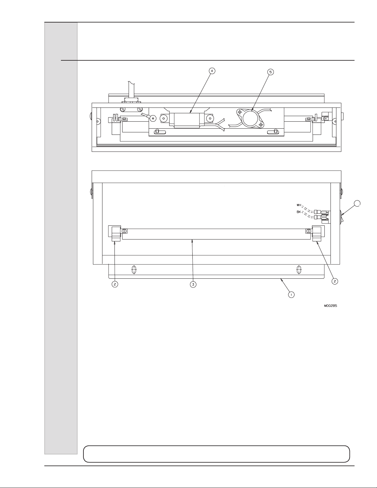
ELECTRO FREEZE
Models 876, 876B, 876C, 876RH, 876BRH, 876CRH
Figure 14 Accessory - Merchandiser
(Optional - Floor Models Only)
Item Part No. Description
1 ............HC117677 .........Sign - Assy. Illuminated 876 (Complete w/o insert)
2 ............HC150574 ......... Socket - Bulb
3 ............HC150578 ......... Bulb - Fluorescent
4 ............HC150577 ......... Ballast - Fluorescent
5 ............HC150576 ......... Starter - Fluorescent
6 ............HC150485 ......... Switch - Rocker SPST
6
Not Shown:
HC165053 ......... Sign - Illuminated Cocktail 876 (Insert)
HC165054 ......... Sign - Illuminated Smoothie 876 (Insert)
HC165055 ......... Sign - Illuminated Lemonade 876 (Insert)
HC165056 ......... Sign - Illuminated Slush 876 (Insert)
HC165025 ......... Decal - Beater Warning
Use only original or authorized replacement parts with this freezer.
Use of unapproved parts will void warranty.
184297 24
Page 72

Keep your freezer in excellent
condition — always contact
your Electro Freeze Distributor
QUALITY PARTS
PROTECT
YOUR
for replacement parts and
maintenance scheduling.
NOTE: Contact your authorized Electro Freeze Distributor for instructions prior to warranty
compressor replacement.
INVESTMENT
 Loading...