

Page 1
Super Cub 25e ARF
Assembly Manual
Page 2

Notice
All instructions, warranties and other collateral
documents are subject to change at the sole
discretion of Horizon Hobby, Inc. For up-to-date
product literature, visit http://www.horizonhobby.
com and click on the support tab for this product.
Meaning of Special Language
The following terms are used throughout the product
literature to indicate various levels of potential harm
when operating this product:
This is a sophisticated hobby product and NOT a
toy. It must be operated with caution and common
sense and requires some basic mechanical
ability. Failure to operate this Product in a safe
and responsible manner could result in injury or
damage to the product or other property. This
product is not intended for use by children without
direct adult supervision. Do not attempt disassembly,
use with incompatible components or augment
product in any way without the approval of Horizon
Hobby, Inc. This manual contains instructions for
safety, operation and maintenance. It is essential to
read and follow all the instructions and warnings
in the manual, prior to assembly, setup or use, in
order to operate correctly and avoid damage or
serious injury.
PROPELLER
Keep loose items that can get entangled in the
propeller away from the prop, including loose clothing
or other objects such as pencils and screwdrivers.
Especially keep your hands away from the propeller as
injury can occur.
BATTERIES
Notes on Lithium Polymer Batteries
When misused, lithium polymer batteries are
significantly more volatile than alkaline or Ni-Cd/
Ni-MH batteries used in RC applications. Always
follow the manufacturer’s instructions when using and
disposing of any batteries. Mishandling of Li-Po batteries
can result in fire causing serious injury and damage.
NOTICE: Procedures, which if not properly followed,
create a possibility of physical property damage
AND a little or no possibility of injury.
CAUTION: Procedures, which if not properly followed,
create the probability of physical property damage
AND a possibility of serious injury.
WARNING: Procedures, which if not properly followed,
create the probability of property damage, collateral
damage, and serious injury OR create a high
probability of superficial injury.
WARNING: Read the ENTIRE instruction
manual to become familiar with the features of the
product before operating. Failure to operate the
product correctly can result in damage to the
product, personal property and cause serious injury.
Warnings
Read and follow all instructions and safety precautions
before use. Improper use can result in fire, serious
injury and damage to property.
Age Recommendation: Not for children under
14 years. This is not a toy.
COMPONENTS
Use only with compatible components. Should any
compatibility questions exist, please refer to the
product instructions, the component instructions or
contact Horizon Hobby, Inc.
FLIGHT
Fly only in open areas to ensure safety. It is
recommended flying be done at AMA (Academy of
Model Aeronautics) approved flying sites. Consult local
laws and ordinances before choosing a location to fly
your aircraft.
SMALL PARTS
This kit includes small parts and should not be left
unattended near children as choking and serious injury
could result.
SAFETY PRECAUTIONS
• Checkallcontrolsurfacespriortoeachtakeoff.
• Donotflyyourmodelnearspectators,parkingareas
or any other area that could result in injury to people
or damage of property.
• Donotflyduringadverseweatherconditions.
Poor visibility and/or strong winds can cause
disorientation and loss of control of your aircraft.
• Donottakechances.Ifatanytimeduringflightyou
observe any erratic or abnormal operation, land
immediately and do not resume flight until the cause
of the problem has been ascertained and corrected.
Safety can never be taken lightly.
• Donotflynearpowerlines.
2 E-flite Super Cub 25e ARF Assembly Manual
Page 3

Table of Contents
Introduction .............................................................. 3
Important Information Regarding
Warranty Information ....................................... 3
Specifications ...........................................................3
Using the Manual .....................................................3
Contents of Kit/Parts Layout ......................................4
Covering Colors ........................................................ 4
Hardware/Accessory Sizes .......................................4
Recommended Radio Equipment ................................ 4
Power 25 Motor Setup ..............................................4
Power 32 Motor Setup ..............................................4
Optional Accessories ................................................4
Required Tools and Adhesives ...................................5
Before Starting Assembly ..........................................5
Hinging the Ailerons and Flaps ................................. 5
Aileron and Flap Servo Installation ............................ 8
Motor and Speed Control Installation .......................13
Cowling, Propeller and Flight Battery Installation ......14
Landing Gear Installation ........................................15
Stabilizer and Tail Bracing Installation ...................... 18
Elevator Installation .................................................20
Rudder Installation ..................................................22
Tail Wheel Installation ............................................. 26
Rudder and Elevator Servo and Linkage Installation . . 27
Receiver Installation without Cockpit Kit .................... 30
Receiver Installation with Cockpit Kit ........................30
Servo Hatch Cover Installation .................................31
Window and Seat Installation .................................. 31
Cockpit Kit Installation (Optional) .............................33
Wing and Wing Strut Installation............................. 34
Lighting Kit Installation (Optional) ............................ 36
Accessory Installation .............................................. 38
Center of Gravity .................................................... 39
Control Throws .......................................................40
Preflight ..................................................................40
Range Test Your Radio ............................................. 41
Flying Your Model ...................................................41
Daily Flight Checks ................................................. 42
Limited Warranty .................................................... 42
Warranty Services ..................................................43
Compliance Information for the European Union ...... 44
Academy of Model Aeronautics
National Model Aircraft Safety Code ..............44
Introduction
For more than half a century, Piper’s Super Cub has
been a favorite of general aviation pilots who spend
most of their time off the beaten path. Its respectable
power, excellent short field performance and rugged
design have made it perfect for back country
transportation, towing gliders or simply getting away
from it all.
The Super Cub 25e ARF expertly captures the look
and feel of this aviation classic with an accurate scale
outline and features unlike anything ever seen in
its power class. This Platinum Series airplane offers
numerous scale details such as a traditional Super
Cub scheme, molded corrugation on the ailerons
and functional flaps, painted aluminum wing struts,
functional shock-absorbing landing gear with scale
Cub wheels and tires, functional split cockpit door, and
more.
But, even with all these scale features, E-flite didn’t
overlook ease of assembly. The two-piece wing and
magnetically secured, factory painted fiberglass
cowling are just a couple of the convenient design
features that make the Super Cub 25e a breeze to
assemble. Even if you add the optional cockpit and
light kits, you can have your airplane ready to fly in a
few evenings. And it will be virtually indistinguishable
from its full scale counterpart and sure to be the envy
of everyone at your flying field!
Important Information
Regarding Warranty Information
Please read our Warranty and Liability Limitations
section before building this product. If you as the
Purchaser or user are not prepared to accept the
liability associated with the use of this Product, you are
advised to return this Product immediately in new and
unused condition to the place of purchase.
Specifications
Wingspan: 68.0 in (1730mm)
Length: 45.5 in (1160mm)
Wing Area: 670 sq in (43.3 sq dm)
Weight with battery: 5.85–6.40 lb
(2.65–2.9 kg)
Weight w/o battery: 5.00–5.60 lb
(2.30–2.55 kg)
Using the Manual
This manual is divided into sections to help make
assembly easier to understand, and to provide breaks
between each major section. In addition, check boxes
have been placed next to each step to keep track
of its completion. Steps with a single circle () are
performed once, while steps with two or more circles
() indicate the step will require repeating, such as
for a right or left wing panel, two servos, etc.
Remember to take your time and follow the directions.
3E-flite Super Cub 25e ARF Assembly Manual
Page 4
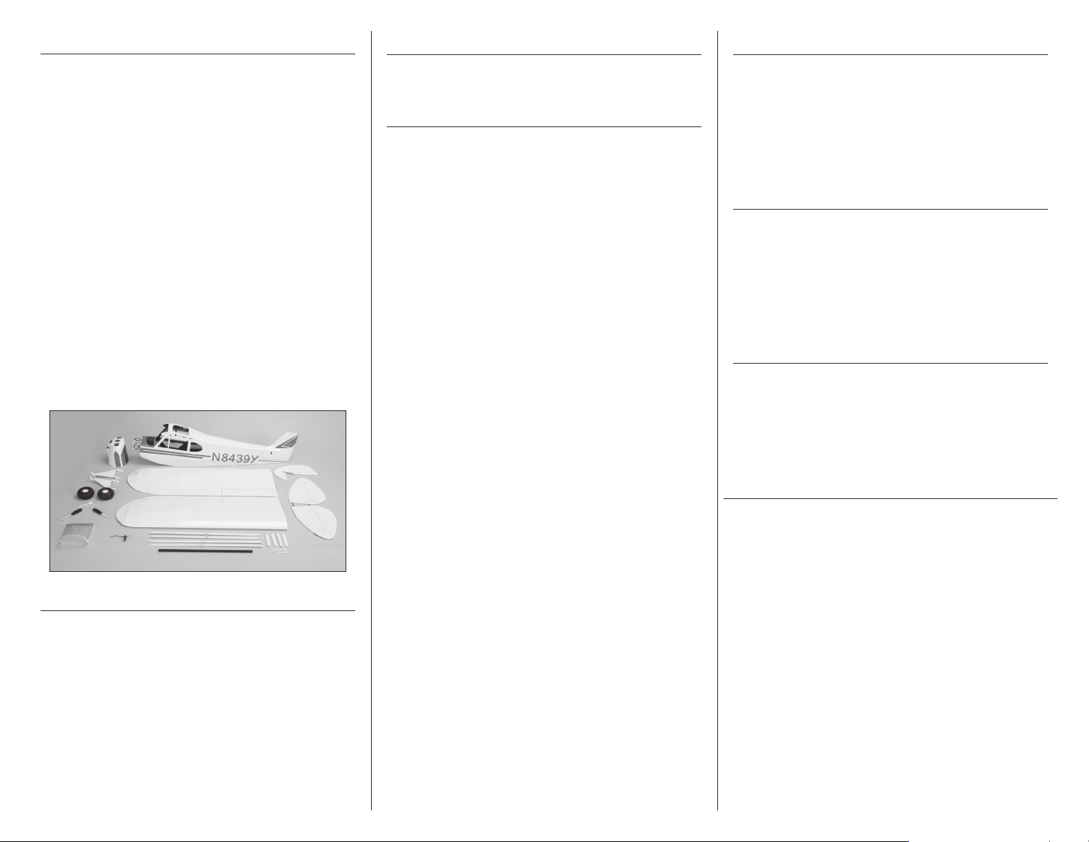
Contents of Kit/Parts Layout
Hardware/Accessory Sizes
Power 25 Motor Setup
Replacement Parts
EFL460001 Wing Set
EFL460002 Fuselage
EFL460003 Tail Set
EFL460004 Rudder
EFL460005 Cowling
EFL460006 Windshield
EFL460007 Top Window
EFL460008 Window Set
EFL460009 Wing Tube
EFL460010 Wheel Set
EFL460011 Tail Wheel
EFL460012 Pushrod Set
EFL460013 Seat Set
EFL460014 Strut Set
EFL460015 Accessory Set
EFL460016 Landing Gear
EFL460017 Hardware Set
EFL460019 Fuselage Hatch
EFL460020 Servo Hatch
Covering Colors
White HANU870
True Red HANU866
Wheel diameter 3.35-inch (85mm)
Wing bolts 1/4-20 x 5/8-inch
Recommended Radio Equipment
You will need a minimum 5-channel transmitter,
receiver and six servos. You can choose to purchase
a complete radio system, or if you are using an
existing transmitter, purchase the other required
equipment separately. We recommend the crystal-free,
interference-free Spektrum™ DX8 2.4GHz DSM2™/
DSMX™ 8-channel system.
If you own the Spektrum DX8 radio or are using a
different DSM2
7-channel DSMX receiver and six Spektrum A5030
mini digital servos.
Complete Radio System
SPM8800 DX8 DSMX 8CH system
Or Purchase Separately
SPMAR7010 AR7010 7CH DSMX™ Receiver
SPMSA5030 A5030 Mini Digital Aircraft
SPMA3051 6-inch (152mm)
SPMA3052 9-inch (229mm)
SPMA3053 12-inch (305mm)
SPMA3050 3-inch (152mm) Servo
SPMA3058 Standard Y-Harness
™
/DSMX™ radio, just add the AR7010
Servo (6)
Servo Extension (2)
(Aileron wing extensions)
Servo Extension
(ESC extension)
Servo Extension (2)
(Aileron to fuse extensions)
Extension
(Bind plug extension)
(Receiver to flap fuselage
extension)
EFLM4025A Power 25 BL Outrunner
Motor, 870Kv
EFLA1060L 60-Amp Pro Switch-Mode
BEC Brushless ESC
EFLB32004S30 3200mAh 4S 14.8V 30C Li-Po,
12AWG EC3
APC13065E 13 x 6.5E Electric Propeller
Power 32 Motor Setup
EFLM4032A Power 32 Brushless Outrunner
Motor, 770Kv
EFLA1060 60-Amp Pro Switch-Mode BEC
Brushless ESC
EFLB32004S30 3200mAh 4S 14.8V 30C Li-Po,
12AWG EC3
APC13065E 13 x 6.5E Electric Propeller
Optional Accessories
EFLA110 Power Meter
EFLC3020 Celectra™ 200W DC Multi-
Chemistry Battery Charger
EFLSP200 2-inch Aluminum Spinner with
4mm and 5mm Collets
EFL460018 Cockpit Kit
LIGHTING KIT
EFLA600 Universal Light Kit Controller
EFLA602 Clear LED Solid (2ea) (2)
EFLA604 Green LED Solid (2ea)
EFLA601 Red LED Solid (2ea)
EFLA620 Extension 36-inch (2ea)
EFLA619 Extension 24-inch (2ea)
EFLA618 Extension 18-inch (2ea) (2)
EFLA617 Y-Harness Heavy Duty 6-inch
DUB435 DuBro 1/16-inch Shrinkwrap
4 E-flite Super Cub 25e ARF Assembly Manual
Page 5

Before Starting Assembly
Hinging the Ailerons and Flaps
We recommend installing the lighting kit and
interior in the sequence of steps shown in the
manual. Adding these items after the model is built
may not be possible without causing damage to
your airframe. Please decide prior to beginning
construction whether or not you would like to
incorporate these items in your airplane.
Required Tools and Adhesives
Tools & Equipment
Box wrench: 10mm Felt-tipped pen
Low-tack tape Flat blade screwdriver
Isopropyl alcohol Hobby knife with #11 blade
Paper towel Nut driver: 1/4-inch
Petroleum jelly Phillips screwdriver: #1, #2
Pin vise Pliers
Ruler Scissors
Side cutters Square
Toothpick T-pins
Mixing sticks Mixing cups
Dental floss Sandpaper
Drill bit: 1/16-inch (1.5mm), 5/64-inch (2mm),
7/64-inch (3mm)
Hex wrench: 1.5mm, 2mm, 3/32-inch, 5/64-inch,
1/8-inch
Optional Tools & Equipment
Balancing stand (optional)
Adhesives
30-minute epoxy PAAPT39
Medium CA PAAPT02
Thin CA PAAPT08
Threadlock PAAPT42
Formula 560 Canopy Glue PAAPT56
Before beginning the assembly of your model, remove
each part from its bag for inspection. Closely inspect
the fuselage, wing panels, rudder and stabilizer for
damage. If you find any damaged or missing parts,
contact the place of purchase.
If you find any wrinkles in the covering, use a heat gun
(HAN100) and covering glove (HAN150) or covering
iron (HAN101) with a sealing iron sock (HAN141) to
remove them. Use caution while working around seams
or areas where the colors overlap to prevent pulling
the seams.
During the course of building your model, we
suggest you use a soft base for the building surface.
Such things as a foam stand, large piece of
bedding foam or a thick bath towel will work well
and help protect the model from damage during
assembly. This is not shown in the instructions
to provide the greatest detail in the photos.
When referencing directions (up, down, left,
right, top and bottom), take note that these are
in relationship to the pilot sitting in the cockpit
of the aircraft unless noted otherwise.
Required Parts
Wing panel (right and left)
Aileron (right and left)
Flap (right and left) Flap hinge (6)
CA hinge (8)
Required Tools and Adhesives
Side cutters Petroleum jelly
T-pins Toothpicks
Thin CA Low-tack tape
Pin vise Drill bit: 1/16-inch (1.5mm)
30-minute epoxy Isopropyl alcohol
Mixing sticks Epoxy cups
Paper towel
1. Locate the wing panel. Separate the aileron and
flap from the wing panel by removing the tape
holding them to the wing panel.
5E-flite Super Cub 25e ARF Assembly Manual
Page 6

2. Locate three hinges for the flaps. Use side cutters
to trim one end of each hinge to 11/16-inch
(17mm). The trimmed end will be placed in the flap.
3. Insert the trimmed end of the hinges into the flap.
Check that the hinge moves perpendicular to the
hinge line. Also check to ensure that the hinge is not
protruding through the top of the flap skin. If you
see a bump, trim a little more off of the hinge.
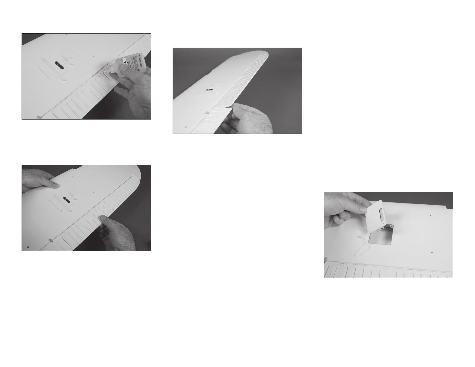
4. Fit the hinge and flap to the wing. Position the
flap so it aligns with the wing and that the hinge
line is equal along the entire length of the flap.
6. Remove each hinge and apply a small amount
of petroleum jelly to the hinge point in order to help
prevent the glue from penetrating the hinge which
could prevent it from operating correctly.
Dipping the hinge knuckles in heated petroleum
jelly (in a liquid state) is easier than trying to
apply it with a toothpick in the gel state.
7. Remove the flap and hinges. Mix a small amount
of 30-minute epoxy. Use a toothpick to apply the
epoxy inside the holes in the wing and flap, then
install the hinges. Check to make sure the flap is
positioned as described in steps 4 and 5.
5. Check that the flap can move freely through its
range of motion. This will ensure that the hinges are
installed correctly.
6 E-flite Super Cub 25e ARF Assembly Manual
Page 7

8. Use a small amount of low-tack tape to hold the
flap in position until the epoxy fully cures. Use a
paper towel and isopropyl alcohol to remove any
excess epoxy before it cures.
9. Repeat steps 1 through 8 to install the
remaining flap.
10. Use a pin vise and 1/16-inch (1.5mm) drill
bit to drill a hole in the center of each hinge slot in
the aileron and wing to create a tunnel for the CA
to wick into. This will allow the CA to penetrate the
hinge, creating a better bond between the hinge and
surrounding wood.
11. Place a T-pin in the center of each of the four
hinges. This will center the hinges equally in the
aileron and wing when they are installed.
12. Insert the hinges in the ailerons. The T-pin will rest
on the edge of the aileron bevel.
13. Slide the aileron into position, guiding the
hinges into the hinge slots in the wing.
14. Remove the T-pins from the hinges. Position the
aileron so the hinge gap is as small as possible.
Also check that the aileron is centered between the
flap and wing tip.
7E-flite Super Cub 25e ARF Assembly Manual
Page 8
15. Saturate each hinge with thin CA. Apply CA to
both the top and bottom of the hinge.
16. Once the CA has cured, gently pull on the
control surface and wing to make sure the hinges are
glued securely. If not, apply CA to those hinges that
are not glued and recheck.
17. Move the control surface through its range of
motion several times to break in the hinges. This
will reduce the initial load on the servo during
your first flights.
18. Repeat steps 10 through 17 to install the
remaining aileron. Once the glue has fully cured on
the flaps, remove the tape placed in step 8.
Aileron and Flap Servo Installation
Required Parts
Wing panel (right and left)
Transmitter Receiver
Nylon clevis (4) Nylon control horn (4)
Receiver battery Silicone tubing (4)
Servo with hardware (4)
2mm x 8mm washer head self-tapping screw (16)
2mm x 8mm self-tapping screw (8)
Aileron pushrod, 2
Flap pushrod, 25/16-inch (59mm) (2)
Servo extension, 6-inch (152mm) (2)
Required Tools and Adhesives
Thin CA Phillips screwdriver: #1
Pin vise Drill bit: 5/64-inch (2mm)
Dental floss Hobby knife with #11 blade
Canopy glue Low-tack tape
1. Remove the aileron servo cover from the wing.
You may need to use a covering iron to reseal the
covering to the wing if the tape lifts the covering.
9
/16-inch (65mm) (2)
8 E-flite Super Cub 25e ARF Assembly Manual
Page 9

2. Prepare the servo by installing the servo
grommets and brass eyelets.
3. Use a #1 Phillips screwdriver to thread a
servo mounting screw into each of the holes to cut
threads in the surrounding wood. Remove the screw
before moving to the next step.
4. Apply 2–3 drops of thin CA in each of the
holes to harden the surrounding wood. This will
harden the threads so the screws do not easily strip
the surrounding wood.
5. Secure the aileron servo to the servo mount
using the hardware included with the servo. Use a
#1 Phillips screwdriver to tighten the screws. Note
that the output for the servo is centered in the slot
where the servo arm will protrude through the cover.
6. Use a pin vise and 5/64-inch (2mm) drill
bit to enlarge the hole in the servo horn. Enlarge
the hole that is 5/8-inch (16mm) from the center of
the horn for the ailerons (1/2-inch (13mm) for the
flaps). Use side cutters to remove any unused arms
so they don’t interfere with the operation of the
servo.
7. Use the radio system to center the aileron
servo. Use the screw from the servo to install the
servo horn on the servo as shown. Use a #1 Phillips
screwdriver to tighten the screw that secures the
servo horn to the servo output.
8. Repeat steps 2 through 7 for the flap servo.
9E-flite Super Cub 25e ARF Assembly Manual
Page 10
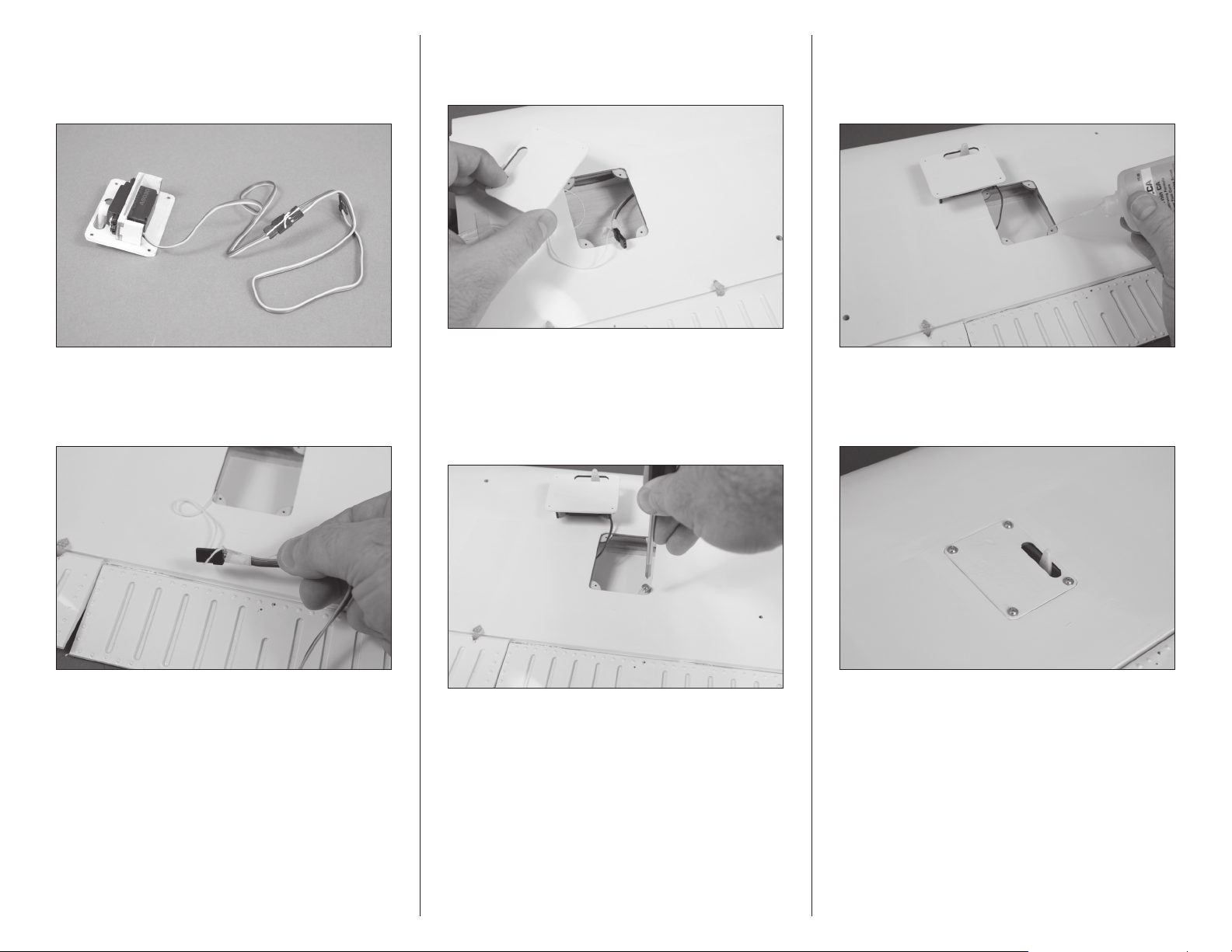
9. Connect a 6-inch (152mm) servo extension to
the servo lead. Use a string or piece of dental floss
to secure the leads so they do not accidentally
disconnect inside the wing.
10. A string is located in the wing to pull the servo
lead through the wing. Tie the string to the end of
the servo lead as shown.
11. Remove the flap servo cover and use the string
to pull the aileron extension through the area of the
hatch for the flap servo.
12. Use a #1 Phillips screwdriver to thread
a 2mm x 8mm washer-head self-tapping screw
into each of the holes to cut threads in the
surrounding wood. Remove the screw before
moving to the next step.
13. Apply 2–3 drops of thin CA in each of
the holes to harden the surrounding wood. This will
harden the threads so the screws do not easily strip
the surrounding wood.
14. Install the servo cover using four 2mm x
8mm washer-head, self-tapping screws and a #1
Phillips screwdriver.
10 E-flite Super Cub 25e ARF Assembly Manual
Page 11

15. Use a #1 Phillips screwdriver to thread a
2mm x 8mm self-tapping screw into each of the pre-
drilled holes to cut threads in the surrounding wood.
Remove the screw before moving to the next step.
17. Remove the control horn backplate from
the control horn using a hobby knife and #11
blade. The backplate can be discarded as it is not
used in the assembly of your model.
19. Slide the small piece of silicone tubing
in a nylon clevis. Thread the clevis 12-turns on a
threaded pushrod wire. This will provide enough
threads in the clevis to be secure and allow for
adjustment of the linkage.
16. Apply 2–3 drops of thin CA in each of
the holes to harden the surrounding wood. This will
harden the threads so the screws do not easily strip
the surrounding wood.
18. Install the servo horn using two 2mm
x 8mm self-tapping screws and a #1 Phillips
screwdriver.
The aileron pushrod measures 29/16-inches
(65mm), while the flap pushrod measures
25/16-inches (59mm). Make sure to use the
correct linkage in the correct location.
20. Repeat steps 9 through 19 for the flap servo.
21. Attach the pushrod wire to the servo horn
using the bend in the wire. With the servo
centered, connect the clevis to the outer hole on
the control horn. Make sure the aileron is centered
when the clevis is connected. Adjust the clevis
as needed to center the aileron. Slide the tubing
over the forks of the clevis to keep it from opening
accidentally in flight.
11E-flite Super Cub 25e ARF Assembly Manual
Page 12
Drawing not to scale
Aileron and Flap
Attach clevis
to the
outer hole
22. Repeat steps 1 through 19 to install the
remaining aileron servo.
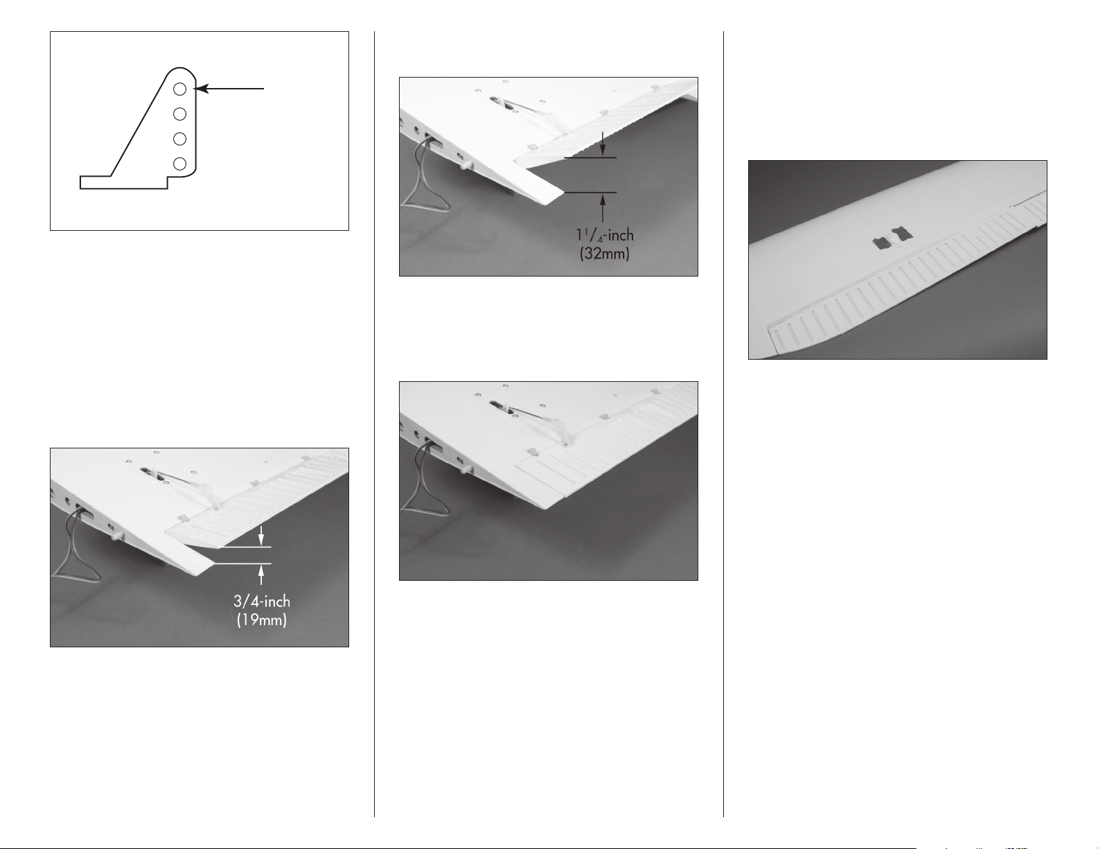
24. Next, set the full-flap position Use the travel
adjustment to set the down flap position as shown.
27. Use canopy glue to attach the scale aileron
linkage cover to the top of the wing. Position
the cover so it is centered along the width of the
aileron. The cover will rest 3/4-inch (19mm)
forward of the hinge line as shown. Use low-tack
tape to hold the cover in position until the glue
fully cures. Install both covers at this time.
If you are using a 2-position flap switch, still set
the center position as a starting point for the
flap linkage installation.
23. Connect the flap linkage to the servo and the
flap control horn. With the flap servo centered,
adjust the linkage to achieve the mid-flap position
as shown.
25. Set the flap switch to the up flap position. Use
the travel adjustment to move the servo so the
trailing edge of the flap is aligned with the trailing
edge of the wing.
26. Repeat steps 23 through 25 for the flap servo.
12 E-flite Super Cub 25e ARF Assembly Manual
Page 13

Motor and Speed Control Installation
Required Parts
Fuselage Motor with hardware
4-40 x 3/4-inch socket head cap screw (4)
Aluminum spacer, 3/8-inch (9.5mm) (4)
Speed control
Servo extension, 9-inch (228mm)
Required Tools and Adhesives
Threadlock Phillips screwdriver: #1
Dental floss Hex wrench: 3/32-inch
Always use threadlock on metal-to-metal fasteners
to prevent them from vibrating loose.
3. Remove the battery hatch by lifting it at the rear.
The rear is held in position with magnets, while the
front is held in position with dowels.
Always use threadlock on metal-to-metal fasteners
to prevent them from vibrating loose.
2. (Power 25) Secure the motor to the firewall using
the four 4-40 x 3/4-inch socket head cap screws.
Use a 3/32-inch hex wrench to tighten the screws.
Make sure to use threadlock on these screws to
prevent them from vibrating loose.
1. Attach the X-mount to the motor using the
hardware included with the motor and a #1
Phillips screwdriver.
2. (Power 32) Secure the motor to the firewall
using the four 3/8-inch (9.5mm) aluminum motor
standoffs and four 4-40 x 3/4-inch socket head cap
screws. Use a 3/32-inch hex wrench to tighten the
screws. Make sure to use threadlock on these screws
to prevent them from vibrating loose.
Matching the colors between the ESC and motor
when they are connected results in the correct
motor direction if using all E-flite components.
4. Connect the leads from the motor to the speed
control. Once connected, position the leads in the
fuselage to prevent them from interfering with the
operation of the motor or battery installation.
13E-flite Super Cub 25e ARF Assembly Manual
Page 14

5. Place the speed control in the fuselage. Use two-
sided tape to secure the speed control in the fuselage
so it rests against the landing gear mount.
6. Connect a 9-inch (228mm) servo extension to the
speed control lead. Use a string or piece of dental
floss to secure the lead so it does not accidentally
disconnect inside the fuselage.
7. Mount the switch in the fuselage using the
hardware provided with the speed control.
8. Guide the extension along the bottom inside the
fuselage. Run the extension back as far as it will
go. Use low-tack tape to prevent the extension from
falling forward in the fuselage until it is plugged
into the mounted receiver.
Cowling, Propeller and
Flight Battery Installation
Required Parts
Fuselage assembly Cowl
Propeller Spinner assembly (not included)
Motor battery Hook and loop strap
Hook and loop tape
Required Tools and Adhesives
Box wrench: 10mm
Hex wrench: 3/32-inch
1. Slide the cowling on the fuselage. The dowels in
the fuselage will position the cowl and the magnets
will hold the cowl to the fuselage.
14 E-flite Super Cub 25e ARF Assembly Manual
Page 15
Landing Gear Installation
Always balance your propeller. An unbalanced
propeller can cause vibrations to be transmitted
into the airframe, which could damage the
airframe or other components as well as
produce unwanted flight characteristics.
We recommend using the optional spinner
to enhance the looks of your model.
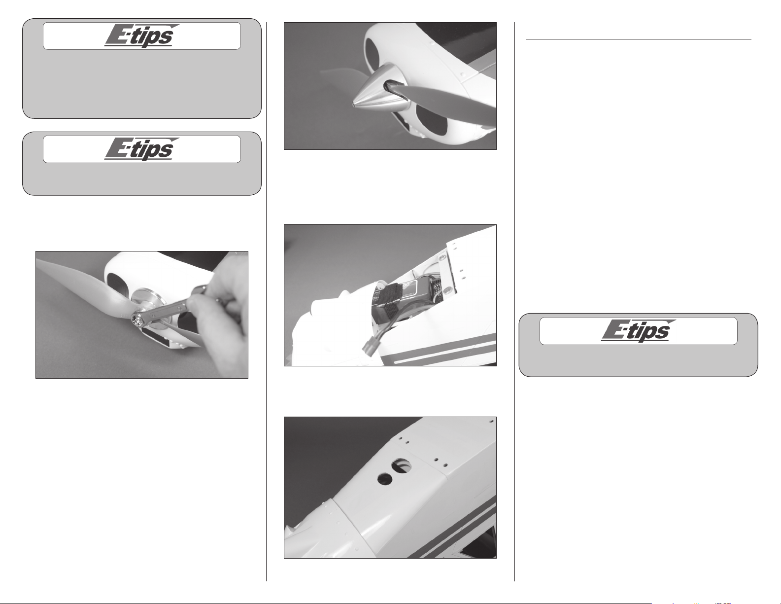
2. Slide the propeller/spinner on the motor shaft. Use
a 10mm box wrench to tighten the nut securing the
assembly to the motor shaft.
4. Secure the motor battery in the fuselage using a
hook and loop strap. We recommend using hook and
loop tape between the battery and battery tray to
keep the battery from sliding on the tray during flight.
Required Parts
Fuselage assembly Landing gear mount (4)
Wing strut tab (2) Landing gear leg (right and left)
4-40 lock nut (10) Axle (2)
Silicone tubing (4) Landing gear shock (2)
6-32-inch setscrew (2)
Main wheel, 3.35-inch (85mm) with hub (2)
2mm x 15mm self-tapping screw (8)
5/32-inch wheel collar with setscrew (2)
4-40 x 5/8-inch socket head cap screws (8)
4-40 x 1/2-inch socket head cap screw (2)
6-32 x 1/2-inch socket head cap screw (8)
Landing gear spreader
Required Tools and Adhesives
Hex wrench: 1.5mm, 3/32-inch, 5/64-inch,
1/8-inch
Flat blade screwdriver
Nut driver: 1/4-inch
Phillips screwdriver: #1
Threadlock
3. Place the spinner cone on the propeller. Use the
screw included with the spinner assembly and a
3/32-inch hex wrench to secure the cone in position.
Make sure the propeller is centered in the openings
so the spinner does not rub against the prop blades,
which could potentially cause them to fail.
Always use threadlock on metal-to-metal fasteners
to prevent them from vibrating loose.
5. Place the battery hatch back into position
on the fuselage.
15E-flite Super Cub 25e ARF Assembly Manual
Page 16

1. Place the wing strut tabs between the rear
landing gear mounts and fuselage. Make sure
the angle on the tab faces toward the top of the
fuselage. Secure the four landing gear mounts and
the two wing strut tabs to the fuselage using eight
6-32 x 1/2-inch socket head cap screws and a
1/8-inch hex wrench. Leave the screws loose so
the mounts can be positioned when installing the
landing gear legs.
3. Attach the landing gear shocks to the landing
gear spreader using two 4-40 x 1/2-inch socket
head cap screws and two 4-40 lock nuts. Tighten
the hardware using a 3/32-inch hex wrench and
a 1/4-inch nut driver. Do not over-tighten the
hardware, preventing the shocks from moving freely
where they are attached to the spreader.
5. Attach the ends of the spreader to the landing gear
using two 4-40 x 5/8-inch socket head cap screws
and two 4-40 lock nuts. Tighten the hardware using a
3/32-inch hex wrench and a 1/4-inch nut driver. Do
not over-tighten the hardware, as it could prevent the
spreader from moving freely where it is attached to
the landing gear.
2. Attach the landing gear legs to the landing gear
mounts using four 4-40 x 5/8-inch socket head cap
screws and four 4-40 lock nuts. Use a 3/32-inch
hex wrench and 1/4-inch nut driver to tighten the
hardware. Do not over-tighten the hardware and
prevent the landing gear from moving. Once the
gear is in position, use a 1/8-inch hex wrench to
fully tighten the hardware securing the landing gear
mounts to the fuselage.
4. Attach the ends of the shocks to the front landing
gear mount using two 4-40 x 5/8-inch socket head
cap screws and two 4-40 lock nuts. Make sure to
place a piece of silicone tubing on either side of
the landing gear spreader to prevent the spreader
from rubbing on the mounts. Tighten the hardware
using a 3/32-inch hex wrench and a 1/4-inch nut
driver. Do not over-tighten the hardware, as it could
prevent the shocks from moving freely where they
are attached to the landing gear mounts.
6. Remove the hub cap from the wheel using a flat
blade screwdriver. Use care not to damage the hub
cap or hub. Remove the outer hub from the wheel at
this time as well.
16 E-flite Super Cub 25e ARF Assembly Manual
Page 17

Always use threadlock on metal-to-metal fasteners
to prevent them from vibrating loose.
7. Use a 1.5mm hex wrench to tighten the setscrew
securing the 5/32-inch wheel collar to the flat on
one end of the axle.
8. Slide the axle through the inner hub in the wheel.
9. Press the outer hub into the tire, aligning the
holes in the outer hub with those in the inner hub.
Use a #1 Phillips screwdriver to install the four 2mm
x 15mm self-tapping screws that secure the hubs
together. Use care in positioning the hubs so the
screws are threaded into the holes in the inner hub.
10. Slide the axle into the landing gear. Use a
5/64-inch hex wrench to tighten a 6/32-inch
setscrew onto the flat on the axle. Make sure the
wheel can rotate freely on the axle.
11. Snap the hub cap on the wheel as shown.
Use a permanent marker to carefully
color the embossed Cub text on the
hub cap for further scale effect.
12. Repeat steps 6 through 11 to install the
remaining axle and wheel.
The inner hub is the one without the holes for
the screws to pass through.
17E-flite Super Cub 25e ARF Assembly Manual
Page 18

Stabilizer and Tail Bracing Installation
Required Parts
Fuselage assembly Stabilizer (right and left)
2-56 x 61/2-inch threaded rod (2)
2-56 x 63/4-inch threaded rod (2)
4-40 x 5/8-inch socket head cap screw (3)
4-40 x 1/4-inch socket head cap screw (2)
4-40 lock nut (3) Nylon brace end (8)
Carbon rod, 5
Carbon rod, 39/16-inch (90mm)
Required Tools and Adhesives
Pin vise Drill bit: 7/64-inch (3mm)
Threadlock Hex wrench: 3/32-inch
Toothpick Nut driver: 1/4-inch
30-minute epoxy Paper towel
Isopropyl alcohol Square
Sandpaper
1
/8-inch (130mm)
2. Slide the stabilizer into position, guiding the
carbon rods through the holes in the fuselage. Slide
the stabilizer so it is tight against the fuselage.
3. Test the fit of the remaining stabilizer on the
stabilizer rods. Both stabilizers must fit snug against
the fuselage as shown. If not, determine the problem
and correct it before proceeding. Do not assume
that the rods are too long and shorten them. The
stabilizer relies on these for structural integrity.
1. Slide the carbon fiber rods into the sockets in the
horizontal stabilizer. The longer 51/8-inch (130mm)
rod is placed toward the front, while the shorter 39/16inch (90mm) rod is positioned toward the trailing
edge. There are caps in the ends of the sockets for the
carbon rod spars. Do not force them in any farther
than they will easily slide.
4. Once the fit has been checked, remove the
stabilizers and carbon rods. Use sandpaper to
lightly sand each of the carbon rods. Mix a small
amount of 30-minute epoxy. Use a toothpick to
apply the epoxy in the holes for the carbon rods in
both stabilizer halves and the fuselage. Place the
stabilizers and carbon rods back into position and
allow the epoxy to fully cure before attaching the
bracing. Remove any excess epoxy before it cures
using a paper towel and isopropyl alcohol.
18 E-flite Super Cub 25e ARF Assembly Manual
Page 19

5. Use a pin vise and 7/64-inch (3mm) drill bit to
enlarge the hole in the eight nylon brace ends.
6. Thread the nylon ends on the two 2-56 x 61/2-
inch threaded rods and the two 2-56 x 63/4-inch
threaded rod.
7. Attach the nylon ends to the stabilizer using
two 4-40 x 5/8-inch socket head cap screws and
two 4-40 lock nuts. Use a 3/32-inch hex wrench
and 1/4-inch nut driver to tighten the hardware.
Leave the hardware slightly loose so the rods can
be positioned.
When installing the rods, make sure they are in
tension with one another slightly. This is what gives
the tail bracing its strength. Nothing should be
warped, and the anchor points are the two attach
points in the bottom of the fuselage. The fin should
not bend to one side and the stab should remain
flat. This may take some adjustment to get right.
8. Adjust the position of the nylon ends so the holes
align with the holes in the fuselage. Use a square
to make sure the stabilizer isn’t being overly-forced
into position. Use a 4-40 x 1/4-inch socket head
screw and a 3/32-inch hex wrench to install the
screws, securing the ends to the fuselage.
Important: The shorter 2-56 x 61/2-inch threaded
rods are located on the bottom of the stabilizer,
and the shorter 2-56 x 63/4-inch threaded rods
are located on the top of the stabilizer.
Always use threadlock on metal-to-metal fasteners
to prevent them from vibrating loose.
19E-flite Super Cub 25e ARF Assembly Manual
Page 20

9. The upper rods are attached to the fin using
a 4-40 x 5/8-inch socket head cap screw and
4-40 locknut. Thread the nylon ends in or out as
necessary to set the length of the rods. Use a square
to check that the stabilizer remains square to the fin
on both the top and bottom of the fuselage.
Elevator Installation
Required Parts
Fuselage assembly CA hinge (6)
Elevator (2) Control horn (2)
2mm x 8mm self-tapping screw (4)
Required Tools and Adhesives
Thin CA Phillips screwdriver: #1
Pin vise Drill bit: 1/16-inch (1.5mm)
T-pins
1. Use a pin vise and 1/16-inch (1.5mm) drill bit
to drill a hole in the center of each hinge slot in the
elevator and stabilizer to create a tunnel for the CA
to wick into. This will allow the CA to penetrate the
hinge, creating a better bond between the hinge and
surrounding wood.
2. Remove the control horn backplate from the
control horn using a hobby knife and #11 blade.
The backplate can be discarded as it is not used in
the assembly of your model.
3. Use a #1 Phillips screwdriver to thread a 2mm x
8mm self-tapping screw into each of the pre-drilled
holes to cut threads in the surrounding wood. Remove
the screw before moving to the next step.
20 E-flite Super Cub 25e ARF Assembly Manual
Page 21

4. Apply 2–3 drops of thin CA in each of the holes
to harden the surrounding wood. This will harden
the threads so the screws do not easily strip the
surrounding wood.
6. Place a T-pin in the center of each of the three
hinges. This will center the hinges equally in the
elevator and stabilizer when they are installed.
8. Slide the elevator into position, guiding the hinges
into the slots in the stabilizer. Make sure the elevator
is installed so the control horn is facing down.
5. Install the control horn using two 2mm x 8mm
self-tapping screws and a #1 Phillips screwdriver.
7. Insert the hinges in the elevator. The T-pin will rest
on the edge of the elevator bevel.
9. Remove the t-pins from the hinges and slide the
elevator tightly against the stabilizer. Check that the
elevator can move without rubbing the stabilizer at
the counter balance.
21E-flite Super Cub 25e ARF Assembly Manual
Page 22

10. Saturate each hinge with thin CA. Apply CA to
both the top and bottom of the hinge.
11. Once the CA has cured, gently pull on the
control surface and stabilizer to make sure the hinges
are glued securely. If not, apply CA to those hinges
that are not glued and recheck.
12. Move the control surface through its range of
motion several times to break in the hinges. This
will reduce the initial load on the servo during your
first flights.
13. Repeat steps 1 through 12 to install the other
elevator half.
Rudder Installation
Required Parts
Fuselage assembly CA hinge (3)
Control horn Rudder tiller arm (2)
2mm nut 2mm x 12mm machine screw
2mm x 8mm self-tapping screw (2)
Required Tools and Adhesives
Thin CA Phillips screwdriver: #1
Pin vise Drill bit: 1/16-inch (1.5mm)
T-pins Hobby knife with #11 blade
Optional Lighting Items
Clear LED light Soldering iron
Heat shrink 36-inch lighting extension
The steps in the grey boxes are steps specific to the
lighting kit. If you will not be installing the lighting
kit you can skip the steps in the grey boxes.
1. Use a pin vise and 1/16-inch (1.5mm) drill bit
to drill a hole in the center of each hinge slot in the
rudder and fin to create a tunnel for the CA to wick
into. This will allow the CA to penetrate the hinge,
creating a better bond between the hinge and
surrounding wood.
22 E-flite Super Cub 25e ARF Assembly Manual
Page 23

A. If you are installing the lighting kit, make sure
to remove the covering from the tube in the rudder
using a hobby knife and #11 blade.
2. Use a #1 Phillips screwdriver to thread a 2mm x
8mm self-tapping screw into each of the pre-drilled
holes to cut threads in the surrounding wood. Remove
the screw before moving to the next step.
4. Remove the control horn backplate from the
control horn using a hobby knife and #11 blade.
The backplate can be discarded as it is not used in
the assembly of your model.
3. Apply 2–3 drops of thin CA in each of the holes
to harden the surrounding wood. This will harden
the threads so the screws do not easily strip the
surrounding wood.
5. Install the control horn using two 2mm x 8mm
self-tapping screws and a #1 Phillips screwdriver.
Always use threadlock on metal-to-metal fasteners
to prevent them from vibrating loose.
23E-flite Super Cub 25e ARF Assembly Manual
Page 24

6. Attach the rudder tiller arms using a 2mm x 12mm
machine screw and 2mm nut. Position the tiller arms
so they face toward the bottom of the rudder and
forward towards the hinge line as shown.
8. Insert the hinges in the rudder. The T-pin will rest
on the edge of the rudder bevel.
B. Use side cutters to remove the plug from the
clear light. Check the fit of the light in the tube in
the rudder. It may be necessary to use a hobby
knife and #11 blade to remove some material
from the rudder to make the light fit flush to the
trailing edge of the rudder. Remove the light once
the fit has been made.
C. Remove the end of the 36-inch (915mm)
lighting extension. Make sure the end that remains
is the end that plugs into the lighting controller.
Slide the extension through the tube in the fuselage
and out at the rudder hinge line.
7. Place a T-pin in the center of each of the three
hinges. This will center the hinges equally in the
aileron and wing when they are installed.
24 E-flite Super Cub 25e ARF Assembly Manual
Page 25

D. The wire can now be passed through the tube
in the rudder. Proceed with hinging the rudder.
10. Saturate each hinge with thin CA. Apply CA to
both the sides of the hinge.
12. Move the control surface through its range of
motion several times to break in the hinges. This
will reduce the initial load on the servo during your
first flights.
9. Slide the rudder into position, guiding the hinges
in the slots in the fin. Remove the T-pins from the
hinges and slide the rudder tightly against the fin.
Check that the rudder can move without rubbing the
fin at the counter balance.
11. Once the CA has cured, gently pull on the
control surface and fin to make sure the hinges are
glued securely. If not, apply CA to those hinges that
are not glued and recheck.
25E-flite Super Cub 25e ARF Assembly Manual
Page 26

E. Carefully solder the extension to the light.
Use care not to melt the wiring by leaving the
soldering iron in position too long. Make sure to
stagger the solder joint so the wires will fit into
the tube in the rudder. Use heat shrink tubing to
protect the connections.
F. Press the light into position in the rudder. It
may be necessary to use a very small amount of
silicone adhesive to keep the light in position.
Tail Wheel Installation
Required Parts
Fuselage assembly Tail wheel bracket
Tail wheel spring (2)
2mm x 10mm washer head self-tapping screw (2)
Required Tools and Adhesives
Thin CA Phillips screwdriver: #1
Pliers Ruler
Side cutters
1. Use a #1 Phillips screwdriver to thread a 2mm
x 10mm washer-head self-tapping screw into each
of the holes to cut threads in the surrounding wood.
Remove the screw before moving to the next step.
2. Apply 2–3 drops of thin CA in each of the holes
to harden the surrounding wood. This will harden
the threads so the screws do not easily strip the
surrounding wood.
3. Install the tail wheel bracket using two 2mm x
10mm washer-head self-tapping screws and a #1
Phillips screwdriver.
26 E-flite Super Cub 25e ARF Assembly Manual
Page 27

4. Use side cutters to remove the flat portion of the
springs. Use pliers to bend the outermost coil at
each end 90 degrees outward to form a hook.
5. Install the spring between the ruder tiller arm and
the steering tiller arm, attaching it to the center hole
in the steering arm.
Rudder and Elevator
Servo and Linkage Installation
Required Parts
Fuselage assembly Servo with hardware (2)
Rudder pushrod Elevator pushrod
Nylon clevis (3) Safety tubing (3)
Transmitter Receiver
Receiver battery
Required Tools and Adhesives
Thin CA Phillips screwdriver: #1
Pin vise Drill bit: 5/64-inch (2mm)
Ruler
1. Remove the tape holding the servo hatch cover
on the fuselage. Set the cover aside. You may need
to use a covering iron to reseal the covering to the
fuselage if the tape lifts the covering.
2. Use a #1 Phillips screwdriver to thread a servo
mounting screw into each of the holes to cut threads
in the surrounding wood. Remove the screw before
moving to the next step. Use care not to press too
hard and damage the servo plate.
3. Apply 2–3 drops of thin CA in each of the holes
to harden the surrounding wood. This will harden
the threads so the screws do not easily strip the
surrounding wood.
6. Repeat steps 4 and 5 to install the remaining tail
wheel spring.
27E-flite Super Cub 25e ARF Assembly Manual
Page 28

4. Prepare the rudder and elevator servo by
Drawing not to scale
Rudder
Attach clevis
to the
outer hole
installing the servo grommets and brass eyelets.
5. Install the rudder and elevator servos using eight
servo mounting screws and a #1 Phillips screwdriver.
6. Insert the rudder pushrod into the tube in the
fuselage. It is easiest to start from outside the
fuselage when inserting the pushrod.
7. Slide the small piece of tubing in a nylon clevis.
Thread the clevis 12-turns on the rudder pushrod
wire. This will provide enough thread in the clevis to
be secure and allow for adjustment of the linkage.
Connect the clevis to the hole shown in the drawing.
28 E-flite Super Cub 25e ARF Assembly Manual
Page 29

8. Use a pin vise and 5/64-inch (2mm) drill bit to
Drawing not to scale
Elevator
Attach clevis
to the
outer hole
enlarge the hole in the servo horn. Enlarge the hole
that is 1/2-inch (13mm) from the center of the horn
as shown. Use side cutters to remove any unused
arms so they don’t interfere with the operation of
the servo.
9. Pass the Z-bend in the pushrod through the
hole enlarged in the previous step. With the
servo centered, attach the servo horn to the servo
using the screw provided with the servo and a #1
Phillips screwdriver.
10. Repeat steps 6 through 9 to install the elevator
pushrod. Make sure to install a clevis for both
elevator control horns
11. With the radio system on and the rudder and
elevator servos centered, check that the control
surfaces are aligned with the fixed surfaces. Use a
ruler between the two surfaces. Adjust the clevis as
necessary to align the surfaces. Once aligned, slide
the silicone tubing over the forks of the clevis to
prevent them from opening accidentally. Check both
elevator and the rudder at this time.
29E-flite Super Cub 25e ARF Assembly Manual
Page 30

Receiver Installation without Cockpit Kit
Required Parts
Fuselage assembly Receiver
Y-harness Hook and loop tape
12-inch (305mm) servo extension (2)
3-inch (76mm) servo extension
Required Tools and Adhesives
Scissors
1. Use scissors to cut two small pieces of hook
and loop tape the size of the receiver and remote
receiver. Plug the rudder and elevator servos
into the correct ports. Plug the 12-inch (305mm)
extensions into the aileron and Aux 1 ports
(this is used for differential aileron throw). Plug
the Y-harness into the flap port. Plug the 3-inch
extension (76mm) into the bind port. Secure the
main and remote receivers in the fuselage using
hook and loop tape.
Receiver Installation with Cockpit Kit
Required Parts
Fuselage assembly Hook and loop tape
12-inch (305mm) servo extension (2)
3-inch (76mm) servo extension
Y-harness
Receiver mount plate (from cockpit kit)
Required Tools and Adhesives
Scissors Medium CA
1. Locate the receiver mount plate in the cockpit kit.
Use medium CA to glue the mount in the fuselage at
the front of the servo mounting tray as shown.
2. 1. Use scissors to cut two small pieces of hook
and loop tape the size of the receiver and remote
receiver. Plug the rudder and elevator servos
into the correct ports. Plug the 12-inch (305mm)
extensions into the aileron and Aux 1 ports
(this is used for differential aileron throw). Plug
the Y-harness into the flap port. Plug the 3-inch
extension (76mm) into the bind port. Secure the
main and remote receivers in the fuselage using
hook and loop tape.
3. Cut a piece of hook and loop tape to attach the
remote receiver to the fuselage side.
30 E-flite Super Cub 25e ARF Assembly Manual
Page 31

Servo Hatch Cover Installation
Required Parts
Fuselage assembly Servo hatch cover
2.5mm x 8mm washer-head self-tapping screw (4)
Required Tools and Adhesives
Thin CA Phillips screwdriver: #1
1. Route the servo leads for the ailerons and
flaps outside the fuselage as shown.
3. Apply 2–3 drops of thin CA in each of the holes
to harden the surrounding wood. This will harden
the threads so the screws do not easily strip the
surrounding wood.
Window and Seat Installation
Required Parts
Fuselage assembly Instrument panel decal
Windscreen Upper window
Seat base (2) Seat (2)
2mm x 8mm self-tapping screw (4)
Side window, front (right and left)
Side window, center (right and left)
Side window, rear (right and left)
Hardwood windscreen support (2)
Required Tools and Adhesives
Thin CA Phillips screwdriver: #1
Medium CA Canopy glue
Scissors
2. Use a #1 Phillips screwdriver to thread a 2.5mm x
8mm washer-head self-tapping screw into each of the
holes to cut threads in the surrounding wood. Remove
the screw before moving to the next step.
4. Install the servo cover using four 2.5mm x
8mm washer-head self-tapping screws and a
#1 Phillips screwdriver.
1. Use scissors to cut the instrument panel from the
decal sheet. Apply the decal in the fuselage.
If you are installing the optional cockpit kit
(EFL460018), you can skip step 1.
31E-flite Super Cub 25e ARF Assembly Manual
Page 32

2. Test fit the hardwood windscreen supports into
position. The supports fit tightly at the top corners
of the windscreen frame and meet at the bottom
as shown. Use medium CA to glue the supports
in position.
3. Test fit the windows and windscreen into position
in the fuselage. The side windows install from
the inside of the fuselage. Apply a thin bead of
canopy glue around the perimeter of the windows
and windscreen. Use low-tack tape to hold them in
position on the fuselage. Make sure the positioning
of the windscreen does not interfere with the
operation of the cockpit door.
6. Apply 2–3 drops of thin CA in each of the holes
to harden the surrounding wood. This will harden
the threads so the screws do not easily strip the
surrounding wood.
4. Use medium CA to glue the door handle
in position.
7. Install the upper window using four 2mm x 8mm
self-tapping screws and a #1 Phillips screwdriver.
5. Use a #1 Phillips screwdriver to thread a 2mm x
8mm self-tapping screw into each of the holes to cut
threads into the surrounding wood. Remove the screw
before moving to the next step.
Important: If installing the optional scale
cockpit, skip the installation of the upper
window until the cockpit kit has been isntalled.
32 E-flite Super Cub 25e ARF Assembly Manual
Page 33

8. Use medium CA to glue the seat supports in
the fuselage. Make sure the CA has fully cured
before proceeding.
Cockpit Kit Installation (Optional)
Required Parts
Fuselage assembly Cockpit kit (optional)
Required Tools and Adhesives
Medium CA Two-sided tape
You can use two-sided tape to secure the floor so it can
be removed in the future, should a component need to
be replaced or a repair to the airframe is necessary.
1. Test fit the pieces of the cockpit kit into the
fuselage. Start by installing the thin plastic floor,
then the thin painted side pieces. The covered
wood side rails are then installed. Once these items
have been fit, you can use medium CA to glue
them in position in the fuselage. Finally, install the
control stick, control pedals and instrument panel in
the fuselage.
9. The seats are held in position with magnets so
they can be removed when installing the wing
bolts. Install the seats as shown. Please note that the
prototype seats are shown; the production seats are
darker in color.
33E-flite Super Cub 25e ARF Assembly Manual
Page 34

2. When installing the upper rear pieces, note that
the piece that fits in the center will slide into the
groove on the side pieces. Make sure the position of
the side pieces is such that the center piece can be
installed.
Wing and Wing Strut Installation
Required Parts
Wing panel (right and left)
Fuselage assembly
Nylon wing bolt (2) Wing strut, front (right and left)
Jury strut fitting (4) Wing strut, rear (right and left)
Jury strut, front (2) Jury strut, rear (2)
Jury strut brace (2) Aluminum wing tube
4-40 lock nut (12) #4 washer (16)
4-40 x 1/2-inch socket head cap screw (4)
4-40 x 3/8-inch socket head cap screw (12)
Required Tools and Adhesives
Hex wrench: 3/32-inch Nut driver: 1/4-inch
1. Slide the aluminum wing tube into the socket in
the wing panel. The tube socket has a cap on it,
so do not force the tube in any farther than it will
easily slide.
34 E-flite Super Cub 25e ARF Assembly Manual
Page 35

2. Install the threaded jury strut fitting in the wing
so the threads are flush with the wing surface.
Important: When threading the jury strut
fittings in the wing, make sure not to thread
them in too far as they can protrude through
the top of the wing.
Important: The jury strut fittings are threaded
so they can be adjusted once the jury struts
and wing struts are installed. The correct height
of the fittings will allow the wing struts to be
straight between the wing and fuselage. This
alignment is described in step 7.
3. Slide the aluminum wing tube into the fuselage.
Guide the flap and aileron extensions into the
fuselage. The wing panel will fit tight against the
fuselage as shown.
5. Temporarily attach the front and rear wing struts
to the wing and wing strut tab. The airfoil of the
struts will match the airfoil of the wing and the
fitting on the wing strut will face toward the wing
as shown in step 7. The longer strut is placed closer
to the trailing edge and the shorter strut toward the
leading edge. Use 4-40 x 3/8-inch socket head cap
screws and #4 washers to attach the strut. Two 4-40
lock nuts will need to be used at the strut fitting. Use
a 3/32-inch hex wrench and 1/4-inch nut driver to
tighten the hardware. Leave the hardware slightly
loose so the strut position can be adjusted when
installing the jury struts.
4. Secure the wing to the fuselage using a nylon
wing bolt.
35E-flite Super Cub 25e ARF Assembly Manual
Page 36

6. Use two 4-40 x 1/2-inch socket head screws,
two 4-40 lock nuts and two #4 washers to attach
the jury struts to the strut fittings on the wing. The
longer jury strut is closer to the flap while the
shorter jury strut is toward the leading edge of
the wing. Leave the hardware slightly loose so the
position of the jury struts can be adjusted.
7. Check to make sure the hole in the jury strut
aligns with the hole in the fitting on the wing
strut. Thread the jury strut fitting in or out as
necessary so the hole aligns with the hole in the
fitting on the wing strut. Check both the front and
rear jury strut fittings.
8. The jury struts will attach to the fittings on the
wing strut closest to the fuselage. Place a #4 washer
on a 4-40 x 3/8-inch socket head cap screw, then
slide the screw through the jury strut and the jury
strut fitting. The jury strut brace is placed on the side
of the fitting closest to the wing tip. A 4-40 lock nut
is then threaded onto the screw.
9. Use a 3/32-inch hex wrench and 1/4-inch nut
driver to tighten all the hardware to secure the wing
struts to the wing and fuselage.
Lighting Kit Installation (Optional)
Required Parts
Wing panel (right and left)
Landing light cover Navigation light cover (2)
Optional Parts
36-inch lighting extension (3)
Lighting Y-harness Clear LED light (2)
Red LED light (L) Green LED light (R)
Required Tools and Adhesives
Soldering iron Heat shrink
Canopy glue
If you are not installing the optional lighting kit, skip
this section of the manual.
1. Check the fit of the light in the tube in the
wing for the landing light. Remove the light once the
fit has been checked.
When removing the wing, only remove the
hardware attaching the wing struts to the wing
strut tab at the fuselage.
10. Repeat steps 2 and 9 to install the remaining
wing strut and jury strut assemblies.
36 E-flite Super Cub 25e ARF Assembly Manual
Page 37

2. Use side cutters to remove the plug from the
clear light. Remove the end of the 36-inch (915mm)
lighting extension. Cut the length of the lead so
when the light is installed, the lead protrudes
approximately 11/2-inches (38mm) from the wing
root. Make sure the end that remains is the end that
plugs into the lighting controller. Slide the extension
through the tube into the wing root and out at the
leading edge.
3. Carefully solder the extension to the light.
Use care not to melt the wiring by leaving the
soldering iron in position too long. Make sure to
stagger the solder joints so the wires will fit into the
tube in the wing. Use heat shrink to cover the solder
joints to prevent shorting the wires.
4. Repeat steps 1 through 3 to prepare the second
landing light. Press the lights into position in the wing.
It may be necessary to use a very small amount of
silicone adhesive to keep the lights in position.
5. Use canopy glue to glue the landing light cover
to the wing. Use low-tack tape to hold the cover in
position until the glue fully cures.
6. Connect the Y-harness for the landing lights
outside the wing as shown.
37E-flite Super Cub 25e ARF Assembly Manual
Page 38

7. Repeat steps 1 through 3 to prepare and install
the navigation light. When installing the navigation
lights, the red will be on the left, and the green will
be on the right. Leave the light extended out so it is
visible in the navigation light cover when the cover
is installed.
8. Install the navigation light cover using canopy
glue. The fit should be tight, so tape will not be
needed to hold the cover in position.
9. Use the template on page 45 to make the cover
for the navigation light lens using adhesive-backed
Ultracote trim sheet.
Accessory Installation
Required Parts
Wing panel (right and left)
Landing light cover Navigation light cover (2)
Required Tools and Adhesives
Canopy glue
1. Use canopy glue to glue the landing light cover
to the wing. Use low-tack tape to hold the cover in
position until the glue fully cures.
2. Install the navigation light cover using canopy
glue. The fit should be tight, so tape will not be
needed to hold the cover in position.
10. Repeat steps 1 through 3, and 7 through 9 to
install the remaining navigation light.
38 E-flite Super Cub 25e ARF Assembly Manual
Page 39

3. Use the template on page 45 to make the cover
Balancing Stand
for the navigation light lens using adhesive backed
Ultracote trim sheet.
Center of Gravity
Required Parts
Assembled airframe
Required Tools and Adhesives
Felt-tipped pen Ruler
Phillips screwdriver: #2
Balancing stand (optional)
An important part of preparing the aircraft for flight is
properly balancing the model.
CAUTION: Do not inadvertently skip this step or
property damage and injury could occur.
3. When balancing your model, support the plane
upright at the marks made on the bottom of the
wing with your fingers or a commercially available
balancing stand. This is the correct balance point
for your model. Make sure your model is assembled
and ready for flight before balancing.
4. Repeat steps 2 and 3 to install the remaining
navigation light.
1. Assemble your model in preparation for flight,
making sure the wing is on securely and the motor
battery is installed as instructed in this manual.
2. The recommended Center of Gravity (CG)
location for your model is 2.75 to 3.00 inches
(70.0 to 76.0mm) back from the leading edge of
the wing as shown with the battery pack installed.
Mark the location of the CG on the top of the wing
with a felt-tipped pen.
Adjust the motor battery as necessary so the model is
level or slightly nose down. This is the correct balance
point for your model. You should find the CG to be
very close with the battery installed as shown in this
manual. Mark the location of the battery on the battery
tray using a felt-tipped pen so it can be returned to this
position if it is removed from your model.
After the first flights, the CG position can be adjusted
for your personal preference.
39E-flite Super Cub 25e ARF Assembly Manual
Page 40

Control Throws
1. Turn on the transmitter and receiver of your
model. Check the movement of the rudder using
the transmitter. When the stick is moved right, the
rudder should also move right. Reverse the direction
of the servo at the transmitter if necessary.
2. Check the movement of the elevator with the
radio system. Moving the elevator stick toward the
bottom of the transmitter should make the airplane
elevator move up.
3. Check the movement of the ailerons with the
radio system. Moving the aileron stick right should
make the right aileron move up and the left
aileron move down.
4. Use a ruler to adjust the throw of the elevator,
ailerons and rudder. Adjust the position of
the pushrod at the control horn to achieve the
following measurements when moving the sticks to
their endpoints.
Elevator
High Rate
Up: 11/8-inch 28mm 15% Expo
Down: 11/8-inch 28mm 15% Expo
Low Rate
Up: 3/4-inch 19mm
Down: 3/4-inch 19mm
Rudder
High Rate
Right: 11/2-inch 38mm
Left: 11/2-inch 38mm
Low Rate
Right: 1-inch 25mm
Left: 1-inch 25mm
Flap
Mid 3/4-inch 19mm
Full 1
Elevator-to-Flap mixing
Mid flap: 5/32-inch (4mm) down elevator
Full flap: 9/32-inch (7mm) down elevator
1
/4-inch 32mm
Preflight
Check Your Radio
Before going to the field, be sure your batteries are
fully charged per the instructions included with your
radio. Charge the transmitter and motor battery
for your airplane. Use the recommended charger
supplied with your particular radio system, following
the instructions provided with the radio. In most
cases, the radio should be charged the night before
going out flying.
Before each flying session, be sure to range check your
radio. See your radio manual for the recommended
range and instructions for your radio system. Each
radio manufacturer specifies different procedures for
their radio systems. Next, run the motor. With the
model securely anchored, check the range again.
The range test should not be significantly affected. If
it is, don’t attempt to fly! Have your radio equipment
checked out by the manufacturer.
Double-check that all controls (aileron, elevator, rudder
and throttle) move in the correct direction.
Measurements are taken at the inner or
widest point on the control surface.
The Super Cub benefits greatly from having aileron
differential. The suggested DX8 transmitter has a
provision for this that will allow you to set this up
without adjusting your ailerons travel volumes. The
differential on the DX8 should be set at 80%. This
setting should allow the travel measurements to match
these below. If not using a DX8, you can also set the
travel adjustment to match the suggested throws.
Aileron
High Rate
Up: 1-inch 25mm
Down: 1/4-inch 6mm
Low Rate
Up: 11/16-inch 18mm
Down: 5/32-inch 4mm
40 E-flite Super Cub 25e ARF Assembly Manual
These are general guidelines measured from our own
flight tests. You can experiment with higher rates to
match your preferred style of flying.
Travel Adjust and Sub-Trims are not listed
and should be adjusted according to each
individual model and preference.
We highly recommend re-binding the radio
system once all the control throws are set. This will
keep the servos from moving to their endpoints
until the transmitter and receiver connect.
Check the radio installation and make sure all the
control surfaces are moving correctly (i.e., the correct
direction and with the recommended throws).
Check all the control horns, servo horns, and clevises
to make sure they are secure and in good condition.
Page 41

Range Test Your Radio
Before each flying session, and especially with a new
model, it is important to perform a range check. It
is helpful to have another person available to assist
during the range check. If you are using a Spektrum
transmitter, please refer to your transmitter’s manual for
detailed instructions on the range check process.
1. With the model resting on the ground, stand 30
paces (approximately 90 feet) away from the model.
2. Face the model with the transmitter in your
normal flying position. Be sure the throttle is in the
full down position and plug the flight battery into
the speed control.
3. As you move the controls, watch to be sure the
airplane’s motor and controls operate smoothly.
You should have total control of the model at 30
paces (90 feet).
Flying Your Model
Okay, it’s time for the moment of truth. Now that you
have your Super Cub at the field and put together, take
the opportunity to check over everything one more time
to ensure that all is in order. Verify control direction,
battery level, CG and range check your model. After
everything checks out, the only thing left to do is
violate some air molecules.
Set your throttle trim to a low idle; this will be your
flight idle. Taxi out to the runway and line up with the
centerline. Smoothly advance the throttle and maintain
directional control with the rudder. The Super Cub is
a very light airplane and has a very large wing, so it
doesn’t take much airspeed to get airborne. If you hold
a little up elevator, the airplane will be off in about 15
feet. If you apply a little down pressure to raise the
tail, you’ll have a longer takeoff run. Once you are
airborne, establish a gentle climb angle and make a
climbing turn to parallel yourself with the runway.
Set up on a downwind leg and reduce power. When
you are abeam your touchdown point, add the first
notch of flaps. Continue your descent into your base
leg and onto final. Gauge your decent rate and let that
be your judge whether or not to fully extend your flaps.
When you are over the threshold, begin to reduce
power to idle. When you get close to the ground,
round out your descent and flare. You should touch
down gently. Once back on the ground, maintain
directional control with the rudder.
That’s it! You’ve just flown your Platinum Series Super
Cub from E-flite. We wish you many more successful
and enjoyable flights with it in the future!
4. If control issues exist, call the appropriate
Horizon Product Support office (see addresses listed
in the Warranty Services section of this manual) or
go to horizonhobby.com to find a local Spektrum
distributor in your country for service if using a
Spektrum radio system.
Once at altitude, you’ll find yourself cruising around
at half throttle. Trim the airplane out and get the feel
for how it flies. Cubs are inherently very gentle, so
you’ll have no issues with maintaining control or
getting behind the airplane. After you have the feel
for it, try your hand at a few basic maneuvers—loops,
rolls, wingovers, spins, etc. The airplane will perform
these with great ease. Many full scale Cubs fly these
barnstorming-type maneuvers, so coupled with the
detail of this Platinum Series design, you’ll have a hard
time distinguishing your airplane from the real one!
Unfortunately, all good things must come to an end
and your flight battery is the malevolent dictator of this
directive. Before you try and set up for a landing, pull
the power back and try some slow flight. Extend the
flaps and get used to how the airplane handles with
flaps extended. They have quite a bit of area, so they
will induce a lot of drag when you have them fully
extended. It’s best in a landing configuration to not try
and drag the airplane in with flaps; you need to aim it
at the ground and fly it in.
41E-flite Super Cub 25e ARF Assembly Manual
Page 42

Daily Flight Checks
Limited Warranty
LIMITATION OF LIABILITY
1. Check the battery voltage of the transmitter
battery. Do not fly below the manufacturer’s
recommended voltage. To do so may cause your
aircraft to crash.
When you check these batteries, ensure you have the
polarities correct on your expanded scale voltmeter.
2. Check all hardware (linkages, screws, nuts, and
bolts) prior to each day’s flight. Be sure that binding
does not occur and that all parts are properly
secured.
3. Ensure all surfaces are moving in the
proper manner.
4. Perform a ground range check before each day’s
flying session.
5. Prior to starting your aircraft, turn off your
transmitter, then turn it back on. Do this each time
you start your aircraft. If any critical switches are on
without your knowledge, the transmitter alarm will
sound a warning.
6. Check that all trim levers are in the
proper location.
WHAT THIS WARRANTY COVERS
Horizon Hobby, Inc. (“Horizon”) warrants to the
original purchaser that the product purchased (the
“Product”) will be free from defects in materials and
workmanship at the date of purchase.
WHAT IS NOT COVERED
This warranty is not transferable and does not cover
(i) cosmetic damage, (ii) damage due to acts of God,
accident, misuse, abuse, negligence, commercial use,
or due to improper use, installation, operation or
maintenance, (iii) modification of or to any part of the
Product, (iv) attempted service by anyone other than
a Horizon Hobby authorized service center, or (v)
Products not purchased from an authorized Horizon
dealer.
OTHER THAN THE EXPRESS WARRANTY ABOVE,
HORIZON MAKES NO OTHER WARRANTY OR
REPRESENTATION, AND HEREBY DISCLAIMS ANY
AND ALL IMPLIED WARRANTIES, INCLUDING,
WITHOUT LIMITATION, THE IMPLIED WARRANTIES
OF NON-INFRINGEMENT, MERCHANTABILITY
AND FITNESS FOR A PARTICULAR PURPOSE.
THE PURCHASER ACKNOWLEDGES THAT THEY
ALONE HAVE DETERMINED THAT THE PRODUCT
WILL SUITABLY MEET THE REQUIREMENTS OF THE
PURCHASER’S INTENDED USE.
PURCHASER’S REMEDY
HORIZON SHALL NOT BE LIABLE FOR SPECIAL,
INDIRECT, INCIDENTAL OR CONSEQUENTIAL
DAMAGES, LOSS OF PROFITS OR PRODUCTION OR
COMMERCIAL LOSS IN ANY WAY, REGARDLESS OF
WHETHER SUCH CLAIM IS BASED IN CONTRACT,
WARRANTY, TORT, NEGLIGENCE, STRICT LIABILITY
OR ANY OTHER THEORY OF LIABILITY, EVEN IF
HORIZON HAS BEEN ADVISED OF THE POSSIBILITY
OF SUCH DAMAGES. Further, in no event shall the
liability of Horizon exceed the individual price of the
Product on which liability is asserted. As Horizon
has no control over use, setup, final assembly,
modification or misuse, no liability shall be assumed
nor accepted for any resulting damage or injury. By
the act of use, setup or assembly, the user accepts all
resulting liability. If you as the purchaser or user are
not prepared to accept the liability associated with the
use of the Product, purchaser is advised to return the
Product immediately in new and unused condition to
the place of purchase.
LAW
These terms are governed by Illinois law (without
regard to conflict of law principals). This warranty
gives you specific legal rights, and you may also have
other rights which vary from state to state. Horizon
reserves the right to change or modify this warranty at
any time without notice.
7. All servo pigtails and switch harness plugs should
be secured in the receiver. Make sure the switch
harness moves freely in both directions.
42 E-flite Super Cub 25e ARF Assembly Manual
Horizon’s sole obligation and purchaser’s sole and
exclusive remedy shall be that Horizon will, at its
option, either (i) service, or (ii) replace, any Product
determined by Horizon to be defective. Horizon
reserves the right to inspect any and all Product(s)
involved in a warranty claim. Service or replacement
decisions are at the sole discretion of Horizon. Proof
of purchase is required for all warranty claims.
SERVICE OR REPLACEMENT AS PROVIDED UNDER
THIS WARRANTY IS THE PURCHASER’S SOLE AND
EXCLUSIVE REMEDY.
Page 43

Warranty Services
QUESTIONS, ASSISTANCE, AND SERVICES
Your local hobby store and/or place of purchase
cannot provide warranty support or service. Once
assembly, setup or use of the Product has been started,
you must contact Horizon directly. This will enable
Horizon to better answer your questions and service
you in the event that you may need any assistance.
For questions or assistance, please direct your
email to productsupport@horizonhobby.com, or call
877.504.0233 toll free to speak to a Product Support
representative. You may also find information on our
website at www.horizonhobby.com.
INSPECTION OR SERVICES
If this Product needs to be inspected or serviced, please
use the Horizon Online Service Request submission
process found on our website or call Horizon to obtain
a Return Merchandise Authorization (RMA) number.
Pack the Product securely using a shipping carton.
Please note that original boxes may be included, but
are not designed to withstand the rigors of shipping
without additional protection. Ship via a carrier that
provides tracking and insurance for lost or damaged
parcels, as Horizon is not responsible for merchandise
until it arrives and is accepted at our facility. An
Online Service Request is available at http://www.
horizonhobby.com under the Support tab. If you
do not have internet access, please contact Horizon
Product Support to obtain a RMA number along with
instructions for submitting your product for service.
When calling Horizon, you will be asked to provide
your complete name, street address, email address
and phone number where you can be reached during
business hours. When sending product into Horizon,
please include your RMA number, a list of the included
items, and a brief summary of the problem. A copy
of your original sales receipt must be included for
warranty consideration. Be sure your name, address,
and RMA number are clearly written on the outside of
the shipping carton.
Notice: Do not ship LiPo batteries to Horizon. If you
have any issue with a LiPo battery, please contact
the appropriate Horizon Product Support office.
WARRANTY REQUIREMENTS
For Warranty consideration, you must include your
original sales receipt verifying the proof-of-purchase
date. Provided warranty conditions have been met,
your Product will be serviced or replaced free of
charge. Service or replacement decisions are at the
sole discretion of Horizon.
NON-WARRANTY SERVICE
Should your service not be covered by warranty
service will be completed and payment will be
required without notification or estimate of the
expense unless the expense exceeds 50% of the
retail purchase cost. By submitting the item for service
you are agreeing to payment of the service without
notification. Service estimates are available upon
request. You must include this request with your item
submitted for service. Non-warranty service estimates
will be billed a minimum of ½ hour of labor. In
addition you will be billed for return freight. Horizon
accepts money orders and cashiers checks, as well as
Visa, MasterCard, American Express, and Discover
cards. By submitting any item to Horizon for service,
you are agreeing to Horizon’s Terms and Conditions
found on our website http://www.horizonhobby.com/
Service/Request/.
UNITED STATES
(Electronics and engines)
Horizon Service Center
4105 Fieldstone Rd
Champaign, Illinois
61822 USA
productsupport@horizonhobby.com
877-504-0233
Online Repair Request visit:
www.horizonhobby.com/repairs
(All other products)
Horizon Product Support
4105 Fieldstone Rd
Champaign, Illinois
61822 USA
productsupport@horizonhobby.com
877-504-0233
UNITED KINGDOM
Horizon Hobby Limited
Units 1-4 Ployters Rd
Staple Tye
Harlow, Essex
CM18 7NS
United Kingdom
sales@horizonhobby.co.uk
+44 (0) 1279 641 097
GERMANY
Horizon Technischer Service
Hamburger Str. 10
25335 Elmshorn
Germany
service@horizonhobby.de
+49 4121 46199 66
FRANCE
Horizon Hobby SAS
14 Rue Gustave Eiffel
Zone d’Activité du Réveil Matin
91230 Montgeron
+33 (0) 1 60 47 44 70
43E-flite Super Cub 25e ARF Assembly Manual
Page 44

Compliance Information for the
European Union
InstructIons for DIsposal of WEEE by
usErs In thE EuropEan unIon
This product must not be disposed of with other waste.
Instead, it is the user’s responsibility to dispose of their
waste equipment by handing it over to a designated
collection point for the recycling of waste electrical
and electronic equipment. The separate collection
and recycling of your waste equipment at the time
of disposal will help to conserve natural resources
and ensure that it is recycled in a manner that
protects human health and the environment. For more
information about where you can drop off your waste
equipment for recycling, please contact your local city
office, your household waste disposal service or where
you purchased the product.
Academy of Model Aeronautics
National Model Aircraft Safety Code
Effective January 1, 2011
A. GENERAL
A model aircraft is a non-human-carrying aircraft
capable of sustained flight in the atmosphere. It may
not exceed limitations of this code and is intended
exclusively for sport, recreation and/or competition.
All model flights must be conducted in accordance with
this safety code and any additional rules specific to the
flying site.
1. Model aircraft will not be flown:
(a) In a careless or reckless manner.
(b) At a location where model aircraft activities are
prohibited.
2. Model aircraft pilots will:
(a) Yield the right of way to all man carrying aircraft.
b) See and avoid all aircraft and a spotter must be
used when appropriate. (AMA Document #540-D-See
and Avoid Guidance.)
(c) Not fly higher than approximately 400 feet above
ground level within three (3) miles of an airport,
without notifying the airport operator.
(d) Not interfere with operations and traffic patterns at
any airport, heliport or seaplane base except where
there is a mixed use agreement.
(e) Not exceed a takeoff weight, including fuel, of
55 pounds unless in compliance with the AMA Large
Model Aircraft program. (AMA Document 520-A)
(f) Ensure the aircraft is identified with the name and
address or AMA number of the owner on the inside or
affixed to the outside of the model aircraft. (This does
not apply to model aircraft flown indoors).
(g) Not operate aircraft with metal-blade propellers or
with gaseous boosts except for helicopters operated
under the provisions of AMA Document #555.
(h) Not operate model aircraft while under the
influence of alcohol or while using any drug which
could adversely affect the pilot’s ability to safely
control the model.
(i) Not operate model aircraft carrying pyrotechnic
devices which explode or burn, or any device which
propels a projectile or drops any object that creates a
hazard to persons or property.
Exceptions:
•FreeFlightfusesordevicesthatburnproducingsmoke
and are securely attached to the model aircraft during
flight.
•Rocketmotors(usingsolidpropellant)uptoaG-series
size may be used provided they remain attached to
the model during flight. Model rockets may be flown in
accordance with the National Model Rocketry Safety
Code but may not be launched from model aircraft.
•OfficiallydesignatedAMAAirShowTeams(AST)are
authorized to use devices and practices as defined
within the Team AMA Program Document (AMA
Document #718).
(j) Not operate a turbine-powered aircraft, unless in
compliance with the AMA turbine regulations. (AMA
Document #510-A).
3. Model aircraft will not be flown in AMA sanctioned
events, air shows or model demonstrations unless:
(a) The aircraft, control system and pilot skills have
successfully demonstrated all maneuvers intended or
anticipated prior to the specific event.
(b) An inexperienced pilot is assisted by an
experienced pilot.
4. When and where required by rule, helmets must be
properly worn and fastened. They must be OSHA,
DOT, ANSI, SNELL or NOCSAE approved or comply
with comparable standards.
B. RADIO CONTROL (RC)
1. All pilots shall avoid flying directly over unprotected
people, vessels, vehicles or structures and shall avoid
endangerment of life and property of others.
2. A successful radio equipment ground-range check
in accordance with manufacturer’s recommendations
will be completed before the first flight of a new or
repaired model aircraft.
44 E-flite Super Cub 25e ARF Assembly Manual
Page 45

3. At all flying sites a safety line(s) must be established in
front of which all flying takes place (AMA Document
#706-Recommended Field Layout):
(a) Only personnel associated with flying the model
aircraft are allowed at or in front of the safety line.
(b) At air shows or demonstrations, a straight safety
line must be established.
(c) An area away from the safety line must be
maintained for spectators.
(d) Intentional flying behind the safety line is
prohibited.
4. RC model aircraft must use the radio-control
frequencies currently allowed by the Federal
Communications Commission (FCC). Only individuals
properly licensed by the FCC are authorized to
operate equipment on Amateur Band frequencies.
5. RC model aircraft will not operate within three
(3) miles of any pre-existing flying site without a
frequency-management agreement (AMA Documents
#922- Testing for RF Interference; #923- Frequency
Management Agreement)
6. With the exception of events flown under official
AMA Competition Regulations, excluding takeoff and
landing, no powered model may be flown outdoors
closer than 25 feet to any individual, except for the
pilot and the pilot’s helper(s) located at the flight line.
7. Under no circumstances may a pilot or other person
touch a model aircraft in flight while it is still under
power, except to divert it from striking an individual.
This does not apply to model aircraft flown indoors.
8. RC night flying requires a lighting system providing
the pilot with a clear view of the model’s attitude and
orientation at all times.
9. The pilot of a RC model aircraft shall:
(a) Maintain control during the entire flight,
maintaining visual contact without enhancement other
than by corrective lenses prescribed for the pilot.
(b) Fly using the assistance of a camera or First-Person
View (FPV) only in accordance with the procedures
outlined in AMA Document #550.
C. FREE FLIGHT
1. Must be at least 100 feet downwind of spectators
and automobile parking when the model aircraft is
launched.
2. Launch area must be clear of all individuals except
mechanics, officials, and other fliers.
3. An effective device will be used to extinguish any fuse
on the model aircraft after the fuse has completed its
function.
D. CONTROL LINE
1. The complete control system (including the safety
thong where applicable) must have an inspection and
pull test prior to flying.
2. The pull test will be in accordance with the current
Competition Regulations for the applicable model
aircraft category.
3. Model aircraft not fitting a specific category shall use
those pull-test requirements as indicated for Control
Line Precision Aerobatics.
4. The flying area must be clear of all utility wires or
poles and a model aircraft will not be flown closer
than 50 feet to any above-ground electric utility lines.
5. The flying area must be clear of all nonessential
participants and spectators before the engine is
started.
NAVIGATION LIGHT TRIM TEMPLATE
45E-flite Super Cub 25e ARF Assembly Manual
Page 46

Building and Flying Notes
46 E-flite Super Cub 25e ARF Assembly Manual
Page 47

Building and Flying Notes
47E-flite Super Cub 25e ARF Assembly Manual
Page 48

TM
© 2011 Horizon Hobby, Inc.
horizonhobby.com
www.e-fliterc.com
The Spektrum trademark is used with permission of Bachmann Industries, Inc.
E-flite, DSM, DSM2, DSMX, Celectra and the Horizon Hobby logo are
All other trademarks, ser vice marks and logos are the property of their respective owners.
18077 Created 04/2011
trademarks or registered trademarks of Horizon Hobby, Inc.
 Loading...