

Page 1
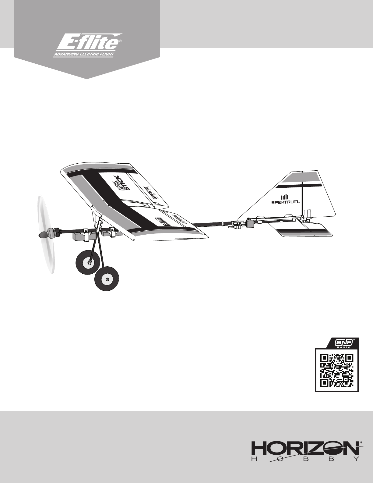
Slow Ultra Stick 1.2m
Instruction Manual
Bedienungsanleitung
Manuel d’utilisation
Manuale di Istruzioni
267459.1 Created 01/23
Scan the QR code and select the Manuals and Support quick links from the
product page for the most up-to-date manual information.
Scannen Sie den QR-Code und wählen Sie auf der Produktseite die Quicklinks
Handbücher und Unterstützung, um die aktuellsten Informationen zu Handbücher.
Scannez le code QR et sélectionnez les liens rapides Manuals and Support sur la
page du produit pour obtenir les informations les plus récentes sur le manuel.
Scannerizzare il codice QR e selezionare i Link veloci Manuali e Supporto dalla
pagina del prodotto per le informazioni manuali più aggiornate.
EFL0350
Page 2

EN
NOTICE
All instructions, warranties and other collateral documents are subject to change at the sole discretion of Horizon Hobby, LLC. For up-to-date product literature, visit
horizonhobby.com or towerhobbies.com and click on the support or resources tab for this product.
MEANING OF SPECIAL LANGUAGE
The following terms are used throughout the product literature to indicate various levels of potential harm when operating this product:
WARNING: Procedures, which if not properly followed, create the probability of property damage, collateral damage, and serious injury OR create a high probability of
supercial injury.
CAUTION: Procedures, which if not properly followed, create the probability of physical property damage AND a possibility of serious injury.
NOTICE: Procedures, which if not properly followed, create a possibility of physical property damage AND little or no possibility of injury.
WARNING: Read the ENTIRE instruction manual to become familiar with the features of the product before operating. Failure to operate the product correctly can
result in damage to the product, personal property and cause serious injury.
This is a sophisticated hobby product. It must be operated with caution and common sense and requires some basic mechanical ability. Failure to operate this Product
in a safe and responsible manner could result in injury or damage to the product or other property. This product is not intended for use by children without direct adult
supervision. Do not use with incompatible components or alter this product in any way outside of the instructions provided by Horizon Hobby, LLC. This manual contains
instructions for safety, operation and maintenance. It is essential to read and follow all the instructions and warnings in the manual, prior to assembly, setup or use, in
order to operate correctly and avoid damage or serious injury.
AGE RECOMMENDATION: Not for children under 14 years. This is not a toy.
Safety Precautions and Warnings
As the user of this product, you are solely responsible for operating in a manner that does not endanger yourself and others or result in damage to the product or the
property of others.
• Always keep a safe distance in all directions around your model to avoid
collisions or injury. This model is controlled by a radio signal subject to
interference from many sources outside your control. Interference can cause
momentary loss of control.
• Always operate your model in open spaces away from full-size vehicles, trafc
and people.
• Always carefully follow the directions and warnings for this and any optional
support equipment (chargers, rechargeable battery packs, etc.).
• Always keep all chemicals, small parts and anything electrical out of the reach
of children.
• Always avoid water exposure to all equipment not specically designed and
protected for this purpose. Moisture causes damage to electronics.
• Never place any portion of the model in your mouth as it could cause serious
injury or even death.
• Never operate your model with low transmitter batteries.
• Always keep aircraft in sight and under control.
• Always use fully charged batteries.
• Always keep transmitter powered on while aircraft is powered.
• Always remove batteries before disassembly.
• Always keep moving parts clean.
• Always keep parts dry.
• Always let parts cool after use before touching.
• Always remove batteries after use.
• Always ensure failsafe is properly set before ying.
• Never operate aircraft with damaged wiring.
• Never touch moving parts.
WARNING AGAINST COUNTERFEIT PRODUCTS: If you ever need to replace your Spektrum receiver found in a Horizon Hobby product, always purchase from
Horizon Hobby, LLC or a Horizon Hobby authorized dealer to ensure authentic high-quality Spektrum product. Horizon Hobby, LLC disclaims all support and warranty
with regards, but not limited to, compatibility and performance of counterfeit products or products claiming compatibility with DSM or Spektrum technology.
2
Slow Ultra Stick 1.2m
Page 3

EN
Included / Recommended Equipment
MOTOR:
ESC:
Servos: A345SL 9g Sub-Micro Digital Servo: 60mm Lead
(SPMSA345SL)
Aileron: (1)
Rudder: (1)
Elevator: (1)
Receiver: AR630 DSMX 6-Channel AS3X & SAFE Receiver (SPMAR630) Installed
Recommended Battery*: 3S 1300mAh 30C Li-Po (SPMX133S30) Required
Recommended Battery Charger: S155 3-cell Li-Po battery charger
(SPMCXC2050)
Recommended Transmitter: Full range 4+ channel 2.4GHz with
Spektrum DSMX®/DSM2 technology with adjustable Dual Rates.
*battery range: 2S-3S 1300-2200mAh LiPo battery
If you own this product, you may be required to register with the FAA. For up-to-date information on how to register with the FAA, please visit https://faadronezone-access.faa.
gov/#/. For additional assistance on regulations and guidance on UAS usage, visit knowbeforeyoufly.org/.
3513-1100Kv Outrunner Motor, 14 pole (SPMXAM2800)
Avian 30-Amp Brushless Smart Lite ESC; 3S-4S, IC3 (SPMXAE30D)
Included
Installed
Installed
Required
Required
Specications
41.in. (1041 mm)
46.7 in. (1188 mm)
Without battery: 28.2oz (801g)
With 3S 1300mAh battery:
32.4 oz (918g)
Table of Contents
Specications .................................................................................... 3
Model Assembly ................................................................................4
Transmitter Setup ..............................................................................9
Battery Installation and ESC Arming ................................................. 10
Binding ............................................................................................ 11
SAFE® Select Switch Designation .....................................................12
Integrated ESC Telemetry ................................................................ 12
Control Direction Test .......................................................................13
AS3X Response Test ........................................................................14
Control Surface Centering and Adjusting a Clevis .............................15
Control Horn and Servo Arm Factory Settings ...................................15
Dual Rates and Control Throws ........................................................15
Center of Gravity (CG) ......................................................................16
SAFE Select Flying Tips ....................................................................16
In-Flight Trimming............................................................................16
Optional Two-Servo Aileron Setup ....................................................17
Post Flight .......................................................................................18
Motor Service .................................................................................. 18
Servo Service ..................................................................................18
Troubleshooting Guide AS3X ............................................................ 18
Troubleshooting Guide .....................................................................19
Replacement Parts ...........................................................................20
Recommended Items ....................................................................... 20
Important Federal Aviation Administration (FAA) Information .............20
Optional Parts ..................................................................................20
Hardware ......................................................................................... 20
AMA National Model Aircraft Safety Code .........................................21
Limited Warranty .............................................................................21
Contact Information .........................................................................22
FCC Information ............................................................................... 22
IC Information .................................................................................. 22
Compliance Information for the European Union ............................... 22
3
Page 4

EN
Model Assembly
Rear Fuselage Section Installation
1. Slide the two fuselage sections together until they click, connecting the front
and rear fuselage sections.
2. Secure the sections together with the two included M2 x 14mm button head
screws. (Use a #1 Phillips screwdriver)
3. The elevator servo plugs have a silver identifying mark. Align these marks and
connect the elevator servo plug to the extension from the receiver. The wire
colors will also align, ensuring correct polarity.
4. Connect the rudder servo plug to the extension from the receiver. These plugs
have no silver mark, use the wire color to align them correctly.
5. Stack the connected plugs and insert them into the retainer.
Disassemble in reverse order.
A
Main Gear Installation
1. Slide one main gear strut (A) into the slot until it engages the retaining latch.
Firm pressure is required to engage the retention latch.
2. Slide the remaining main gear strut (B) into the opposite slot until it latchs.
Disassemble in reverse order, using a tool such as a at screwdriver to release the
retention latch.
B
M2 x 14mm
Button-Head
Machine Screw
A
4
Slow Ultra Stick 1.2m
Page 5

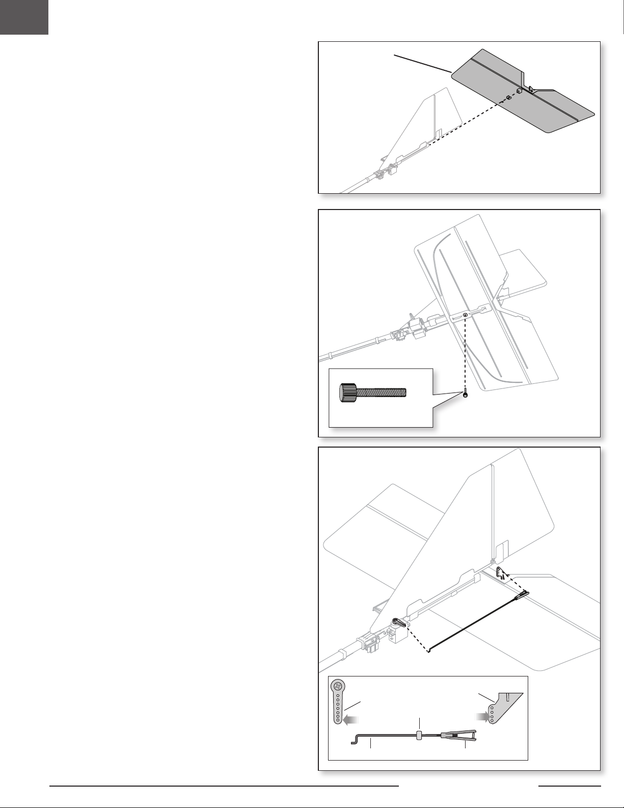
Vertical Stabilizer Installation
1. Slide the vertical stabilizer (A) on the rear fuselage tube until the holes align.
2. There are two pushrods in the parts bag for the rudder and elevator. Choose
longer one and use it for the rudder.
3. Connect the 193mm rudder pushrod z-bend to the outermost hole in the servo
arm.
4. Attach the clevis to the third outermost hole of the rudder control horn (see
instructions for clevis connection).
EN
B
A
Rudder Control Horn
Retaining Tube
PushrodClevis
Rudder Servo Arm
5
Page 6
EN
Horizontal Stabilizer Installation
1. Ensure the control horn is facing up, then slide the horizontal stabilizer (A) on
the rear fuselage tube until the bottom screw holes align.
2. Secure the vertical and horizontal stabilizers using the included
M3 x 22mm thumb screw (B).
3. Connect the 180mm elevator pushrod z-bend to the outermost hole in the
servo arm.
4. Attach the clevis to the third outermost hole of the elevator control horn (see
instructions for clevis connection).
Disassemble in reverse order.
A
B
M3 x 22mm
Thumb Screw
Elevator Servo Arm
Retaining Tube
Pushrod Clevis
6
Elevator Control Horn
Slow Ultra Stick 1.2m
Page 7

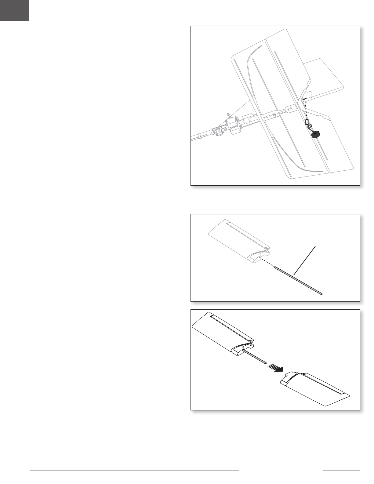
Tail Wheel Installation
1. Align the tail wheel wire with the recess in the bottom of the rudder.
2. Press the tail wheel wire into the recess until the wire clicks into place.
Disassemble in reverse order.
EN
Wing Installation
1. Slide the wing tube (A) into the wing.
2. Slide the two wing halves together.
A
7
Page 8

EN
Wing Installation
1. Align and place the wing retainer (B) on top of the wing.
2. Align the wing with the three pins on the front wing mount, then slide the wing
forward into place.
3. Secure the wing to mounts with two included M3 x 22mm thumb screws (C)
4. Connect the aileron servo connector to the servo extension from the receiver.
5. Connect the aileron pushrods to the control horns in the indicated locations
Disassemble in reverse order.
B
(2) M3 x 22mm
Thumb Screw
Aileron Servo Arm
Aileron Control Horn
C
Retaining Tube
Pushrod Clevis
8
Slow Ultra Stick 1.2m
Page 9

Transmitter Setup
EN
WARNING: Enable the throttle cut feature. Always engage throttle cut
before approaching the aircraft.
WARNING: Never assign Aux 2 to SAFE Select during transmitter setup
with any model transmitter. If SAFE Select is assigned to Aux 2, the
throttle channel/motor will reverse in ight once SAFE is enabled. Motor
reversing is assigned to Aux 2/channel 7 by default in the Smart ESC.
IMPORTANT: After you set up your model, always rebind the transmitter and
receiver to set the desired failsafe positions.
IMPORTANT: The included receiver has been programmed specically for
operation in this aircraft.
†
Some of the terminology and function locations used in the iX12, iX14 and
iX20 programming may be slightly different than other Spektrum AirWare™
radios. The names given in parentheses correspond to the iX12, iX14 and
iX20 programming terminology. Consult your transmitter manual for specic
information about programming your transmitter.
Pre-Programmed Transmitter Setup Files
To save time when setting up your transmitter for this model, visit
www.SpektrumRC.com to download the latest pre-programmed transmitter setup
les. Locate the le for this model using the item number. Download the correct
model le and install it in your transmitter using an SD card.
1. Go to SpektrumRC.com
2. Hover over Support and click on Support Hub from the menu that appears.
3. Scroll and select your transmitter from the list.
4. Scroll to Quick Links and click on Manuals & Support.
5. Click on the Transmitter Preset Download link.
6. Follow preset model les import instruction for the preset model les.
Computerized Transmitter Setup
Start all transmitter programming with a blank ACRO model (perform a model
reset), then name the model.
2 Position switch 3 Position switch
Set Dual Rates to
Set Servo Travel to 100%
Set Throttle Cut to -100%
‡
DX6e
DX6 ‡ (Gen2)
DX7‡ (Gen2)
‡
NX6
DX8e
DX8 (Gen2)
DX9
DX10t
DX18
DX20
†
iX12
†
iX20
NX6
NX8
NX10
1. Go to the SYSTEM SETUP (Model Utilities)†
2. Set MODEL TYPE: AIRPLANE
3. Set AIRCRAFT TYPE: (Model Setup, Aircraft Type)†:
WING: Normal
HIGH 100%
LOW 70% LOW 50%
HIGH 100%
MID 70%
Exponential
After rst ights, you may adjust exponential in your transmitter.
Dual Rates
Low rate is recommended for the initial ights.
NOTICE: To ensure AS3X® technology functions properly, do not lower rate
values below 50%. If lower rates are desired, manually adjust the position of the
pushrods on the servo arm.
NOTICE: If oscillation occurs at high speed, refer to the Troubleshooting Guide
for more information.
Transmitter Telemetry Setup
If the transmitter that you intend to use with this aircraft is not displaying
telemetry data, visit www.SpektrumRC.com and update your rmware. With the
latest rmware installed on your transmitter the telemetry option should now be
functional on your transmitter.
9
Page 10

EN
Battery Installation and ESC Arming
Battery Selection
We recommend the 3S 1300mAh 30C Smart Li-Po Battery. Refer to the Optional
Parts List for other recommended batteries. If using a battery other than those
listed, the battery should be within the range of capacity, dimensions and weight of
the Spektrum Li-Po battery packs to t in the fuselage.
1. Lower the throttle and throttle trim to the lowest settings. Power on the
transmitter, then wait 5 seconds.
2. Install a fully charged battery (A) in the battery tray as shown and secure it
using the hook and loop straps (B).
3. Connect the battery to the ESC.
4. Keep the aircraft immobile and away from wind or the system will
not initialize.
• The ESC will sound a series of tones (refer to step 6 of the binding
instructions for more information).
• An LED will light on the receiver.
CAUTION: Always keep hands away from the propeller. When armed,
the motor will turn the propeller in response to any throttle movement.
A
B
10
Slow Ultra Stick 1.2m
Page 11

EN
Binding
General Binding Tips and Failsafe
• The included receiver has been specically programmed
for operation of this aircraft. Refer to the receiver manual
for correct setup if the receiver is replaced.
• Keep away from large metal objects while binding.
• Do not point the transmitter’s antenna directly at the receiver while binding.
• The orange LED on the receiver will ash rapidly
when the receiver enters bind mode.
Transmitter and Receiver Binding / Enabling SAFE Select
The BNF Basic version of this airplane includes SAFE Select technology, enabling you to choose the level of ight protection. SAFE mode includes angle limits and
automatic self leveling. AS3X mode provides the pilot with a direct response to the control sticks. SAFE Select is enabled or disabled during the bind process.
With SAFE Select disabled the aircraft is always in AS3X mode. With SAFE Select enabled the aircraft will be in SAFE Select mode all the time, or you can assign a switch
to toggle between SAFE Select and AS3X modes.
IMPORTANT: Before binding, read the transmitter setup section in this manual and complete the transmitter setup table to ensure your transmitter is properly
programmed for this aircraft.
IMPORTANT: Move the transmitter ight controls (rudder, elevators, and ailerons) and the throttle trims to neutral. Move the throttle to low before and
during binding.
You can use either the bind button on the receiver or the conventional bind plug to complete the binding process.
A bind plug extension has been provided in BNF Basic version models. It will be labeled and located in the battery or radio compartment for easy access.
• Once bound, the receiver will retain its bind settings
for that transmitter until you re-bind.
• If the receiver loses transmitter communication, the failsafe will activate.
Failsafe moves the throttle channel to low throttle. Pitch and roll
channels move to actively stabilize the aircraft in a descending turn.
• If problems occur, refer to the troubleshooting guide or if needed,
contact the appropriate Horizon Product Support ofce.
Using Bind Button Using Bind Plug
SAFE Select Enabled
Connect PowerLower Throttle
SAFE Select Enabled: The control surfaces cycle back and forth twice with
a slight pause at neutral position every time the receiver is powered on.
SAFE Select Disabled
Press and hold Bind
Button
Release Bind ButtonOrange Flashing LED Bind TX to RX
Press Bind ButtonLower Throttle Connect Power
SAFE Select Enabled
BIND
Install Bind Plug
SAFE Select Enabled:
slight pause at neutral position every time the receiver is powered on.
Lower Throttle Connect Power
BIND
Remove Bind Plug
The control surfaces cycle back and forth twice with a
Bind TX to RXOrange Flashing LED
SAFE Select Disabled
BIND
Install Bind Plug Connect PowerLower Throttle
Orange Flashing LED
SAFE Select Disabled: The control surfaces cycle back and forth once
every time the receiver is powered on.
SAFE Select can also be activated via Forward Programming in compatible transmitters.
Bind TX to RXRelease Bind Button
BIND
Bind TX to RXOrange Flashing LED
SAFE Select Disabled: The control surfaces cycle back and forth once
every time the receiver is powered on.
Remove Bind Plug
11
Page 12

EN
SAFE® Select Switch Designation
Stick Inputs
Once SAFE Select is enabled, you can choose to y in SAFE mode full-time, or
assign a switch. Any switch on any channel between 5 and 9 can be used on your
transmitter.
If the aircraft is bound with SAFE Select disabled, the aircraft will be in AS3X mode
exclusively.
CAUTION: Keep all body parts well clear of the propeller and keep the
aircraft securely restrained in case of accidental throttle activation.
IMPORTANT: To be able to assign a switch, rst verify:
• The aircraft was bound with SAFE Select enabled.
• Your choice for the SAFE Select switch is assigned to a channel between
5 and 9 (Gear, Aux1-4), and travel is set at 100% in each direction.
• The aileron, elevator, rudder and throttle direction are set to normal,
not reverse.
• The aileron, elevator, rudder and throttle are set to 100% travel. If dual
rates are in use, the switches need to be in the 100% position.
See your transmitter manual for more information about assigning a switch to a channel.
Assigning a Switch
1. Power on the transmitter.
2. Power on the aircraft.
3. Hold both transmitter sticks to the inside bottom corners, and toggle the
desired switch 5 times quickly (1 toggle = full up and down).
4. The control surfaces of the aircraft will move, indicating the switch has been
selected.
Repeat the process to assign a different switch or to deactivate the current switch.
SAFE Select Switch Assignment Stick Positions
Mode 1 and 2 transmitters
Assigned Switch
100%
X 5
100%
TIP: Use the channel monitor to verify channel movement.
This example of the channel
monitor shows the stick
positions for assigning a
switch, the switch selection
on Aux2, and +/- 100%
travel on the switch.
-100
100
-100
Monitor
-100
-100
-100
+/-100
-100
-100
Forward Programming
Assign the SAFE Select channel through forward programming on your compatible
Spektrum transmitter.
For more information about setting SAFE Select and using
Forward Programming, please refer to the following link for a
detailed video:
https://www.youtube.com/watch?v=o-46P066cik
Integrated ESC Telemetry
This aircraft includes telemetry between the ESC and receiver, which can provide
information including RPM, voltage, motor current, throttle setting (%), and FET
(speed controller) temperature.
For more information about compatible transmitters, firmware updates, and how
to use the telemetry technology on your transmitter, visit www.SpektrumRC.com.
DX series,
NX series,
iX series
DX series,
NX series,
iX series
THR
AIL
ELE
RUD
GER
AX1
AX2
AX3
AX4
Forward Programming SAFE Select Setup
1. Begin with the transmitter bound to the receiver.
2. Power ON the transmitter.
3. Assign a switch for SAFE Select that is not already in
use for another function. Use any open channel between
5 and 9 (Gear, Aux1-4).
4. Set switch H (throttle cut) to prevent accidental motor operation.
5. Power ON the aircraft. A signal bar appears on your transmitter’s
main screen when the telemetry information is being received.
6. Go to the FUNCTION LIST (Model Setup)
7. Select Forward Programming; Select Gyro Settings,
Choose SAFE Select to enter the menu.
8. Set SAFE Select Ch: To the channel you have chosen for SAFE
Select.
9. Set AS3X and SAFE On or Off as desired for each switch position.
Telemetry Setup
1. Begin with the transmitter bound to the receiver.
2. Power ON the transmitter.
3. Set switch H (throttle cut) to prevent accidental motor operation.
4. Power ON the aircraft. A signal bar appears on your transmitter’s
main screen when the telemetry information is being received.
5. Go to the FUNCTION LIST (Model Setup)
6. Select TELEMETRY; Smart ESC
7. Set Total Cells: 3
8. Set LVC Alarm: 3.4V Set Alarm; Voice/Vibe
9. Set pole count; 14 pole
12
Slow Ultra Stick 1.2m
Page 13

Control Direction Test
Switch on the transmitter and connect the battery. Use the transmitter to operate
the aileron, elevator and rudder controls. View the aircraft from the rear when
checking the control directions.
This model has a built in aileron to rudder mix, when the ailerons are deected the
rudder will move.
EN
Transmitter Command Control SurfaceResponse
Elevator
1. Pull the elevator stick back. The elevators should move up, which will cause
the aircraft to pitch up.
2. Push the elevator stick forward. The elevators should move down, which will
cause the aircraft to pitch down.
Ailerons
1. Move the aileron stick to the right. The right aileron should move up and the
left aileron down, which will cause the aircraft to bank right.
2. Move the aileron stick to the left. The left aileron should move up and the right
aileron down, which will cause the aircraft to bank left.
Rudder
1. Move the rudder stick to the right. The rudder should move to the right, which
will cause the aircraft to yaw right.
2. Move the rudder stick to the left. The rudder should move to the left, which will
cause the aircraft to yaw left.
ElevatorAileronRudder
13
Page 14

EN
AS3X Response Test
This test ensures that the AS3X® control system is functioning properly. Assemble
the aircraft and bind your transmitter to the receiver before performing this test.
1. Raise the throttle just above 25%, then lower the throttle to activate AS3X.
CAUTION: Keep all body parts, hair and loose clothing away from a
moving propeller, as these items could become entangled.
2. Move the entire aircraft as shown and ensure the control surfaces move in
the direction indicated in the graphic. If the control surfaces do not respond
as shown, do not y the aircraft. Refer to the receiver manual for more
information.
Once the AS3X system is active, control surfaces may move rapidly. This is normal.
AS3X remains active until the battery is disconnected.
Due to different effects of torque, lift, and drag some aircraft require trim changes
with different speeds and throttle settings. Mixes are preloaded into the receiver to
compensate for these changes. The mixes become active the rst time the throttle
is raised above 25%. The control surfaces may be offset slightly at different throttle
settings after the rst time throttle is raised. Trimming the plane in ight should be
done at 80-100% throttle for best results.
Aircraft movement AS3X Reaction
ElevatorAileronRudder
14
Slow Ultra Stick 1.2m
Page 15

Control Surface Centering and Adjusting a Clevis
IMPORTANT: Perform the Control Direction Test before performing control surface
centering.
While SAFE is inactive, mechanically center the control surfaces.
IMPORTANT: Correct operation of the SAFE system requires sub-trim and trim at 0.
After binding a transmitter to the receiver, set the trims and sub-trims to 0, ensure
the servo arms are in the correct positions, then adjust the linkages to center the
control surfaces.
Remove the clevis
1. Slide the retaining tube off the clevis.
2. Carefully spread the clevis and remove the clevis pin from the control horn.
Adjust the clevis
3. Turn the clevis to adjust the length of the pushrod.
Re-install the clevis
4. Carefully spread the clevis, then insert the clevis pin into the specied hole in
the control horn.
5. Move the retaining tube to secure the clevis on the control horn.
EN
1.
2.
3.
4.
5.
6.
Control Horn and Servo Arm Factory Settings
The table to the right shows the factory settings for the control horns and servo
arms. Fly the aircraft at factory settings before making changes.
More control throw Less control throw
Dual Rates and Control Throws
Program your transmitter to set the rates and control throws to the values given.
These values have been tested and are a good starting point to achieve successful
ight.
Elevator
Rudder
Ailerons
Aileron
Elevator
Rudder
Control Horns Servo Arms
High Rate Low Rate
p = 12mm
q = 12mm
p = 15mm
q = 15mm
= 25mm
= 25mm
p = 8mm
q = 8mm
p = 11mm
q = 11mm
= 15mm
= 15mm
15
Page 16

EN
Center of Gravity (CG)
The CG location is measured from the leading edge of the wing. This CG location
has been determined with the recommended 3S 1300mAh Li-Po battery
(SPMX133S30) installed to the front edge of the battery tray. Adjust the battery
forward or aft as needed to achieve the proper CG location.
CAUTION: Install the battery but do not arm the ESC while checking the CG.
Personal injury may result.
SAFE Select Flying Tips
When flying in SAFE Select mode the aircraft will return to level flight any time the
aileron and elevator controls are at neutral. Applying aileron or elevator control
will cause the airplane to bank, climb or dive. The amount the stick is moved will
determine the attitude the airplane flies. Holding full control will push the aircraft
to the pre-determined bank and roll limits, but it will not go past those angles.
When flying with SAFE Select, it is normal to hold the control stick deflected with
moderate aileron input when flying through a turn. To fly smoothly with SAFE Select,
avoid making frequent control changes and don’t attempt to correct for minor deviations. Holding deliberate control inputs will command the aircraft to fly at a specific
angle, and the model will make all corrections to maintain that flight attitude.
When flying with SAFE Select, throttle will make the aircraft climb or descend. Full
throttle will cause the aircraft to pitch up and climb slightly. Mid throttle will keep the
airplane flying level. Low throttle will cause the airplane to descend slightly nose-down.
Return the elevator and aileron controls to neutral before switching from SAFE
Select mode to AS3X mode. If you do not neutralize controls when switching into
AS3X mode, the control inputs used for SAFE Select mode will be excessive for
AS3X mode and the aircraft will react immediately.
115mm +/-5
behind the leading
edge.
Differences between SAFE Select and AS3X modes
This section is generally accurate but does not take into account flight speed,
battery charge status, and other limiting factors.
SAFE Select AS3X
Control stick
is neutralized
Holding a
small amount
of control
Holding full
control
Control Input
Throttle
Aircraft will self level
Aircraft will bank or pitch to a
moderate angle and maintain
the attitude
Aircraft will bank or pitch to the
predetermined angle limits and
maintain the attitude
Full throttle: Climb
Neutral: Level flight
Low throttle: Descend
Aircraft will continue to
fly at its present attitude
Aircraft will continue to
pitch or roll slowly
Aircraft will continue to
roll or pitch rapidly
Throttle will not affect
flight response.
In-Flight Trimming
During your rst ight, trim the aircraft for level ight at 80-100% throttle. Make
small trim adjustments with your transmitter’s trim switches to achieve straight
and level ight.
After adjusting trim do not touch the control sticks for 3 seconds. This allows the
receiver to learn the correct settings to optimize AS3X performance.
Failure to do so could affect ight performance.
16
3 Seconds
Slow Ultra Stick 1.2m
Page 17

Optional Two-Servo Aileron Setup
1. Remove the wing from the aircraft.
2. Remove the servo arm screw and the installed servo arm.
3. Removed the servo arm from the z-bend of each pushrod.
4. Remove the 2 screws securing the servo to the wing.
5. Reposition the servo to the left of the servo pocket, aligning it with the left
position screw holes.
6. Route the servo wire and connector out of the servo pocket and secure the
servo with the 2 screws.
7. Install a second aileron servo (SPMSA345SL, not included) in the right servo
position in the servo pocket.
8. Route the servo plug and connector in the right channel exiting the servo
pocket and align the screws with screw holes and secure in place.
9. Connect the right servo into channel 2 and the left servo into channel 6 of the
receiver.
10. In your transmitter System Setup change Aircraft Type to Dual Aileron.
11. Connect a battery to the aircraft and power ON the aircraft to center the servos.
12. Connect the z-bend of the control linkages to the outermost hole of the new
servo horn (EFL0370, required and not included). Repeat for the other servo
horn.
13. Install the servo horn on the servo as close to 90 degrees as possible and
secure with screw.
14. Install the clevis end of the new linkage to outermost hole of the aileron control
horn.
15. Ensure the aileron control surfaces are centered, if necessary adjust the
pushrod mechanically to center the aileron.
16. Install the wing on the fuselage.
EN
Aileron Servo Arm
Aileron Control Horn
Retaining Tube
Pushrod Clevis
Computerized Transmitter Setup
Start all transmitter programming with a blank ACRO model (perform a model
reset), then name the model.
2 Position switch 3 Position switch
Set Dual Rates to
HIGH 100%
LOW 70% LOW 50%
Set Servo Travel to 100%
Set Throttle Cut to -100%
‡
DX6e
DX6 ‡ (Gen2)
DX7‡ (Gen2)
‡
NX6
1. Go to the SYSTEM SETUP (Model Utilities)†
2. Set MODEL TYPE: AIRPLANE
DX8e
DX8 (Gen2)
DX9
DX10t
DX18
DX20
iX12
iX20
†
†
3. Set AIRCRAFT TYPE: (Model Setup, Aircraft Type)†:
WING: Dual Aileron
NX6
NX8
NX10
HIGH 100%
MID 70%
17
Page 18

EN
Post Flight
1. Disconnect the ight battery from the ESC (required for safety and
battery life).
2. Power OFF the transmitter.
3. Remove the ight battery from the aircraft.
4. Repair or replace all damaged parts.
Motor Service
CAUTION: Always disconnect the ight battery before performing motor service.
Disassembly
1. Remove the spinner (A), screw (B), spinner retainer (C), propeller nut (D) and
propeller (E).
2. Remove the 4 screws (F) from the propeller shaft (G).
3. Remove the propeller shaft from the prop adapter.
4. Remove the 2 screws (H) from the motor mount (I) and the fuselage.
5. Disconnect the motor wires from the ESC wires.
Assembly
Assemble in reverse order.
• Correctly align and connect the motor wire colors with the ESC wires.
• Install the propeller with the size numbers (11 x 5.5) facing forward.
• Tighten the propeller nut using a 10mm wrench.
• Push the rubber spinner back on to the plastic spinner retainer.
5. Store the ight battery apart from the aircraft and monitor the
battery charge.
6. Make note of the ight conditions and ight results, planning for future ights.
E
H
I
D
B
G
F
C
Wiring not shown
A
Servo Service
Control Surface Replacement Servo Description
Aileron (1)
SPMSA345SL A345SL 9g Sub-Micro Digital ServoElevator (1)
Rudder (1)
Troubleshooting Guide AS3X
Problem Possible Cause Solution
Damaged propeller or spinner Replace propeller or spinner
Imbalanced propeller Balance the propeller.
Motor vibration Replace parts or correctly align all parts and tighten fasteners as needed
Oscillation
Inconsistent ight
performance
Incorrect response to the
AS3X Control Direction Test
Aircraft will not respond
to throttle but responds to
other controls
Loose receiver Align and secure receiver in fuselage
Loose aircraft controls Tighten or otherwise secure parts (servo, arm, clevis, horn and control surface)
Worn parts Replace worn parts (especially propeller, spinner or servo)
Irregular servo movement Replace servo
Trim is not at neutral If you adjust trim more than 8 clicks, adjust the clevis to remove trim
Sub-Trim is not at neutral No Sub-Trim is allowed. Adjust the servo linkage
Aircraft was not kept immobile for
5 seconds after battery connection
Incorrect direction settings in the
receiver, which can cause a crash
Throttle not at idle and/or throttle
trim too high
Throttle servo travel is lower than
100%
Throttle channel is reversed Reverse throttle channel on transmitter
Motor disconnected from ESC Make sure motor is connected to the ESC
With the throttle stick in lowest position. Disconnect battery, then reconnect battery and keep the
aircraft still for 5 seconds
DO NOT y. Contact Product Support for a solution.
Reset controls with throttle stick and throttle trim at lowest setting
Make sure throttle servo travel is 100% or greater
18
Slow Ultra Stick 1.2m
Page 19

Troubleshooting Guide
Problem Possible Cause Solution
Extra propeller noise or
extra vibration
Reduced ight time or
aircraft underpowered
Aircraft will not Bind (during
binding) to transmitter
Aircraft will not connect
(after binding) to transmitter
Control surface does not
move
Controls reversed Transmitter settings are reversed Perform the Control Direction Test and adjust the controls on transmitter appropriately
Motor pulses then motor
loses power
Damaged propeller and spinner, prob adapter or motor Replace damaged parts
Propeller is out of balance Balance or replace propeller
Prop nut is too loose Tighten the prop nut
Flight battery charge is low Completely recharge ight battery
Propeller installed backwards Install propeller with numbers facing forward
Flight battery damaged Replace ight battery and follow ight battery instructions
Flight conditions may be too cold Make sure battery is warm before use
Battery capacity too low for flight conditions Replace battery or use a larger capacity battery
Transmitter too near aircraft during binding process
Aircraft or transmitter is too close to large metal
object, wireless source or another transmitter
The bind plug is not installed correctly in the bind port Install bind plug in bind port and bind the aircraft to the transmitter
Flight battery/transmitter battery charge is too low Replace/recharge batteries
Bind switch or button not held long enough during bind
process
Transmitter too near aircraft during connecting
process
Aircraft or transmitter is too close to large metal
object, wireless source or another transmitter
Bind plug left installed in bind port Rebind transmitter to the aircraft and remove the bind plug before cycling power
Aircraft bound to different model memory
(ModelMatchTM radios only)
Flight battery/Transmitter battery charge is too low Replace/recharge batteries
Transmitter may have been bound to a different aircraft
using different DSM protocol
Control surface, control horn, linkage or servo
damage
Wire damaged or connections loose Do a check of wires and connections, connect or replace as needed
Transmitter is not bound correctly or the incorrect
airplanes was selected
Flight battery charge is low Fully recharge ight battery
BEC (Battery Elimination Circuit) of the ESC is damaged Replace ESC
ESC uses default soft Low Voltage Cutoff (LVC) Recharge ight battery or replace battery that is no longer performing
Weather conditions might be too cold Postpone flight until weather is warmer
Battery is old, worn out, or damaged Replace battery
Battery C rating might be too low Use recommended battery
Move powered transmitter a few feet from aircraft, disconnect and reconnect
ight battery to aircraft
Move aircraft and transmitter to another location and attempt binding again
Power off transmitter and repeat bind process. Hold transmitter bind button or
switch until receiver is bound
Move powered transmitter a few feet from aircraft, disconnect and reconnect
ight battery to aircraft
Move aircraft and transmitter to another location and attempt connecting again
Select correct model memory on transmitter
Bind aircraft to transmitter
Replace or repair damaged parts and adjust controls
Re-bind or select correct airplanes in transmitter
EN
19
Page 20

EN
Replacement Parts Optional Parts
Part # Description
EFL0351 Right Wing: Slow Ultra Stick
EFL0352 Left Wing: Slow Ultra Stick
EFL0353 Wing Joiner: Slow Ultra Stick
EFL0354 Wing Tube: Slow Ultra Stick
EFL0355 Thumb Screw Set: Slow Ultra Stick
EFL0356 Front Wing Support: Slow Ultra Stick
EFL0357 Rear Wing Support: Slow Ultra Stick
EFL0358 Mounting Tray: Slow Ultra Stick
EFL0359 Motor Mount: Slow Ultra Stick
EFL0360 Rubber Spinner: Slow Ultra Stick
EFL0361 Propeller Adapter: Slow Ultra Stick
EFL0362 Landing Gear Set: Slow Ultra Stick
EFL0363 Control Horn Set: Slow Ultra Stick
EFL0364 Control Link Set: Slow Ultra Stick
EFL0365 Wire Retainer Set:: Slow Ultra Stick
EFL0366 Fuselage: Slow Ultra Stick
EFL0367 Fuselage Joiner: Slow Ultra Stick
EFL0368 Vertical Stabilizer: Slow Ultra Stick
EFL0369 Horizontal Stabilizer: Slow Ultra Stick
EFL0370 Servo Arm Set: Slow Ultra Stick
EFL0371 Decal Sheet: Slow Ultra Stick
EFL0372 Hardware Set: Slow Ultra Stick
EFLP1155 Propeller: 11 X 5.5
SPMSA345SL A345SL 9g Sub-Micro Servo; 60mm L
SPMXAE30D Avian 30A Brushless Smart Lite ESC
SPMXAM2800 Brushless Motor: 3513-1100Kv, 14-Pole
SPMAR630 AR630 DSMX 6-Channel AS3X & SAFE Receiver
Recommended Items
Part # Description
SPMR6655 DX6e 6 Ch Transmitter Only
SPMX133S30 1300mAh 3S 11.1V Smart G2 30C;
SPMXC2050 Smart S155 G2 AC 1x55W Charger
Part # Description
SPMR8105 DX8e 8 Ch Transmitter Only
SPMR6775 NX6 6 Ch Transmitter Only
SPMR8200 NX8 8 Ch Transmitter Only
SPMXC2080 Smart S1100 G2 AC Charger, 1x100W
SPMX22003S30 2200mAh 3S 11.1V Smart 30C; IC3
SPMX223S30 2200mAh 3S 11.1V Smart G2 30C;
APC11055E Electric Propeller, 11 x 5.5E
SPMSA345SL A345 9g Sub-Micro Digital Servo; 60mm Lead
EFL0370 Servo Arm Set: Slow Ultra Stick
Hardware
Quantity Item Use
4 M3 x 6mm machine screw
1 M2 x 6mm machine screw
1 M3 x 22mm thumb screw
3 2.3 x 4.5mm self-tapping screw To secure servo arm to servo
4 2 x 8mm self-tapping screw
M3 x 22mm machine thumb
2
screw
1 M3 x 6mm machine screw To secure spinner retaining washer
1 M6 propeller screw nut
4 M2 x 7mm machine screw
1 M2 x 14mm machine screw
1 M2 x 14mm machine screw
1 M2 x 14mm machine screw
1 M2 x 14mm machine screw
1 M2 x 6mm machine screw
6 2 x 8mm self-tapping screw
4 M2 x 14mm machine screw
1 12.8mm x 500mm Wing tube
Diameter 85mm, Width 17mm,
2
Axle 3mm
Diameter 21mm, Width 7mm,
1
Axle 1.3mm
To secure the motor to the motor
mount
To secure the ESC mount to the
fuselage
To secure the horizontal stablizer
to the fuselage
To secure control horn to control
surface
To secure wing to fuselage
To secure the propeller to propeller
shaft
To secure the propeller adapter to
the motor
To secure the motor mount to the
fuselage
To secure the battery mount to the
fuselage
To secure the wing front mount to
the fuselage
To secure the wing rear mount to
the fuselage
To secure the receiver mount to
the fuselage
To secure the servos to the
fuselage
To secure the two halves of the
fuselage together
Main wheel
Tail wheel
Important Federal Aviation Administration (FAA) Information
Use the QR code below to learn more about the Recreational UAS Safety Test
(TRUST), as was introduced by the 2018 FAA Reauthorization Bill. This free test is
required by the FAA for all recreational yers in the United States. The completed
certicate must be presented upon request by any FAA or law enforcement ofcial.
20
If your model aircraft weighs more than .55lbs or 250 grams, you are required by
the FAA to register as a recreational yer and apply your registration number to the
outside of your aircraft. To learn more about registering with the FAA, use the QR
code below.
Slow Ultra Stick 1.2m
Page 21

AMA National Model Aircraft Safety Code
Academy of Model Aeronautics
National Model Aircraft Safety Code
Effective January 1, 2018
A model aircraft is a non-human-carrying device capable of sustained ight within visual line of sight of the pilot or spotter(s). It may not exceed limitations of this code
and is intended exclusively for sport, recreation, education and/or competition. All model ights must be conducted in accordance with this safety code and related AMA
guidelines, any additional rules specic to the ying site, as well as all applicable laws and regulations.
As an AMA member I agree:
• I will not y a model aircraft in a careless or reckless manner.
• I will not interfere with and will yield the right of way to all human-carrying
aircraftusing AMA’s See and Avoid Guidance and a spotter when appropriate.
• I will not operate any model aircraft while I am under the inuence of alcohol or
any drug that could adversely affect my ability to safely control the model.
• I will avoid ying directly over unprotected people, moving vehicles, and
occupied structures.
• I will y Free Flight (FF) and Control Line (CL) models in compliance with AMA’s
safety programming.
• I will maintain visual contact of an RC model aircraft without enhancement other
than corrective lenses prescribed to me. When using an advanced ight system,
such as an autopilot, or ying First-Person View (FPV), I will comply with AMA’s
Advanced Flight System programming.
• I will only y models weighing more than 55 pounds, including fuel, if certied
through AMA’s Large Model Airplane Program.
• I will only y a turbine-powered model aircraft in compliance with AMA’s Gas
Turbine Program.
• I will not y a powered model outdoors closer than 25 feet to any individual,
except for myself or my helper(s) located at the ightline, unless I am taking off
and landing, or as otherwise provided in AMA’s Competition Regulation.
• I will use an established safety line to separate all model aircraft operations
from spectators and bystanders.
Limited Warranty
What this Warranty Covers
Horizon Hobby, LLC, (Horizon) warrants to the original purchaser that the product
purchased (the “Product”) will be free from defects in materials and workmanship at
the date of purchase.
What is Not Covered
This warranty is not transferable and does not cover (i) cosmetic damage, (ii) damage
due to acts of God, accident, misuse, abuse, negligence, commercial use, or due to
improper use, installation, operation or maintenance, (iii) modification of or to any part
of the Product, (iv) attempted service by anyone other than a Horizon Hobby authorized
service center, (v) Product not purchased from an authorized Horizon dealer, (vi)
Product not compliant with applicable technical regulations, or (vii) use that violates
any applicable laws, rules, or regulations.
OTHER THAN THE EXPRESS WARRANTY ABOVE, HORIZON MAKES NO OTHER WARRANTY
OR REPRESENTATION, AND HEREBY DISCLAIMS ANY AND ALL IMPLIED WARRANTIES,
INCLUDING, WITHOUT LIMITATION, THE IMPLIED WARRANTIES OF NON-INFRINGEMENT,
MERCHANTABILITY AND FITNESS FOR A PARTICULAR PURPOSE. THE PURCHASER
ACKNOWLEDGES THAT THEY ALONE HAVE DETERMINED THAT THE PRODUCT WILL
SUITABLY MEET THE REQUIREMENTS OF THE PURCHASER’S INTENDED USE.
Purchaser’s Remedy
Horizon’s sole obligation and purchaser’s sole and exclusive remedy shall be that
Horizon will, at its option, either (i) service, or (ii) replace, any Product determined by
Horizon to be defective. Horizon reserves the right to inspect any and all Product(s)
involved in a warranty claim. Service or replacement decisions are at the sole
discretion of Horizon. Proof of purchase is required for all warranty claims. SERVICE
OR REPLACEMENT AS PROVIDED UNDER THIS WARRANTY IS THE PURCHASER’S
SOLE AND EXCLUSIVE REMEDY.
Limitation of Liability
HORIZON SHALL NOT BE LIABLE FOR SPECIAL, INDIRECT, INCIDENTAL OR
CONSEQUENTIAL DAMAGES, LOSS OF PROFITS OR PRODUCTION OR COMMERCIAL
LOSS IN ANY WAY, REGARDLESS OF WHETHER SUCH CLAIM IS BASED IN CONTRACT,
WARRANTY, TORT, NEGLIGENCE, STRICT LIABILITY OR ANY OTHER THEORY OF
LIABILITY, EVEN IF HORIZON HAS BEEN ADVISED OF THE POSSIBILITY OF SUCH
DAMAGES. Further, in no event shall the liability of Horizon exceed the individual price
of the Product on which liability is asserted. As Horizon has no control over use, setup,
final assembly, modification or misuse, no liability shall be assumed nor accepted for
any resulting damage or injury. By the act of use, setup or assembly, the user accepts
all resulting liability. If you as the purchaser or user are not prepared to accept the
liability associated with the use of the Product, purchaser is advised to return the
Product immediately in new and unused condition to the place of purchase.
Law
These terms are governed by Illinois law (without regard to conflict of law principals).
This warranty gives you specific legal rights, and you may also have other rights which
vary from state to state. Horizon reserves the right to change or modify this warranty
at any time without notice.
WARRANTY SERVICES
Questions, Assistance, and Services
Your local hobby store and/or place of purchase cannot provide warranty support or
service. Once assembly, setup or use of the Product has been started, you must contact
your local distributor or Horizon directly. This will enable Horizon to better answer your
questions and service you in the event that you may need any assistance. For questions
or assistance, please visit our website at www.horizonhobby.com, submit a Product
Support Inquiry, or call the toll free telephone number referenced in the Warranty and
Service Contact Information section to speak with a Product Support representative.
Inspection or Services
If this Product needs to be inspected or serviced and is compliant in the country you
live and use the Product in, please use the Horizon Online Service Request submission
process found on our website or call Horizon to obtain a Return Merchandise
Authorization (RMA) number. Pack the Product securely using a shipping carton.
Please note that original boxes may be included, but are not designed to withstand
the rigors of shipping without additional protection. Ship via a carrier that provides
tracking and insurance for lost or damaged parcels, as Horizon is not responsible for
merchandise until it arrives and is accepted at our facility. An Online Service Request
is available at http://www.horizonhobby.com/content/service-center_render-servicecenter. If you do not have internet access, please contact Horizon Product Support to
obtain a RMA number along with instructions for submitting your product for service.
When calling Horizon, you will be asked to provide your complete name, street
address, email address and phone number where you can be reached during business
hours. When sending product into Horizon, please include your RMA number, a list of
the included items, and a brief summary of the problem. A copy of your original sales
receipt must be included for warranty consideration. Be sure your name, address, and
RMA number are clearly written on the outside of the shipping carton.
NOTICE: Do not ship LiPo batteries to Horizon. If you have any issue with a
LiPo battery, please contact the appropriate Horizon Product Support ofce.
Warranty Requirements
For Warranty consideration, you must include your original sales receipt verifying the
proof-of-purchase date. Provided warranty conditions have been met, your Product will
be serviced or replaced free of charge. Service or replacement decisions are at the
sole discretion of Horizon.
Non-Warranty Service
Should your service not be covered by warranty, service will be completed and payment
will be required without notification or estimate of the expense unless the expense
exceeds 50% of the retail purchase cost. By submitting the item for service you are
agreeing to payment of the service without notification. Service estimates are available
upon request. You must include this request with your item submitted for service. Nonwarranty service estimates will be billed a minimum of ½ hour of labor. In addition you
will be billed for return freight. Horizon accepts money orders and cashier’s checks, as
well as Visa, MasterCard, American Express, and Discover cards. By submitting any item
to Horizon for service, you are agreeing to Horizon’s Terms and Conditions found on our
website http://www.horizonhobby.com/content/service-center_render-service-center.
ATTENTION: Horizon service is limited to Product compliant in the country of
use and ownership. If received, a non-compliant Product will not be serviced.
Further, the sender will be responsible for arranging return shipment of the
un-serviced Product, through a carrier of the sender’s choice and at the
sender’s expense. Horizon will hold non-compliant Product for a period of
60days from notication, after which it will be discarded.
10/15
EN
21
Page 22

EN
Contact Information
Country of Purchase Horizon Hobby Contact Information Address
Horizon Service Center (Repairs and Repair Requests) servicecenter.horizonhobby.com/RequestForm/
United States
of America
European Union
Horizon Product Support (Product Technical Assistance)
Sales
Horizon Technischer Service service@horizonhobby.de
Sales: Horizon Hobby GmbH +49 (0) 4121 2655 100
productsupport@horizonhobby.com
877-504-0233
websales@horizonhobby.com
800-338-4639
2904 Research Rd
Champaign, Illinois, 61822 USA
Hanskampring 9
D 22885 Barsbüttel, Germany
FCC Information
FCC ID: BRWSPMAR630
Supplier’s Declaration of Conformity
EFL Slow Ultra Stick Manual 1.2M BNF Basic(EFL0350)
This device complies with part 15 of the FCC Rules. Operation is subject to
the following two conditions: (1) This device may not cause harmful
interference, and (2) this device must accept any interference received,
including interference that may cause undesired operation.
CAUTION: Changes or modications not expressly approved by the party
responsible for compliance could void the user’s authority to operate the
equipment.
NOTE: This equipment has been tested and found to comply with the limits for
a Class B digital device, pursuant to part 15 of the FCC Rules. These limits are
designed to provide reasonable protection against harmful interference in a
residential installation. This equipment generates, uses and can radiate radio
frequency energy and, if not installed and used in accordance with the instructions,
may cause harmful interference to radio communications. However, there is
no guarantee that interference will not occur in a particular installation. If this
equipment does cause harmful interference to radio or television reception, which
can be determined by turning the equipment off and on, the user is encouraged to
try to correct the interference by one or more of the following measures:
• Reorient or relocate the receiving antenna.
• Increase the separation between the equipment and receiver.
• Connect the equipment into an outlet on a circuit different from that to which
the receiver is connected.
• Consult the dealer or an experienced radio/TV technician for help.
Horizon Hobby, LLC
2904 Research Rd.,
Champaign, IL 61822
Email: compliance@horizonhobby.com
Web: HorizonHobby.com
IC Information
IC: 6157A-SPMAR630
CAN ICES-3 (B)/NMB-3(B)
This device contains license-exempt transmitter(s)/receivers(s) that comply with
Innovation, Science, and Economic Development Canada’s license-exempt RSS(s).
Operation is subject to the following 2 conditions:
1. This device may not cause interference.
2. This device must accept any interference, including interference that may
cause undesired operation of the device.
Compliance Information for the European Union
EU Compliance Statement:
EFL Slow Ultra Stick Manual 1.2M BNF Basic (EFL0350); Hereby,
Horizon Hobby, LLC declares that the device is in compliance with the
following: EU Radio Equipment Directive 2014/53/EU, RoHS 2 Directive
2011/65/EU, RoHS 3 Directive - Amending 2011/65/EU Annex II 2015/863
The full text of the EU declaration of conformity is available at the following internet
address: https://www.horizonhobby.com/content/support-render-compliance.
Wireless Frequency Range and Wireless Output Power:
2402-2478MHz
4.65dBm
WEEE NOTICE:
This appliance is labeled in accordance with European Directive
2012/19/EU concerning waste of electrical and electronic equipment
(WEEE). This label indicates that this product should not be disposed of
with household waste. It should be deposited at an appropriate facility
to enable recovery and recycling.
EU Manufacturer of Record:
Horizon Hobby, LLC
2904 Research Road
Champaign, IL 61822 USA
EU Importer of Record:
Horizon Hobby, GmbH
Hanskampring 9
22885 Barsbüttel Germany
Australia/New Zealand:
22
Slow Ultra Stick 1.2m
Page 23

HINWIES
Allen Anweisungen, Garantien und anderen zugehörigen Dokumenten sind Änderungen nach Ermessen von Horizon Hobby, LLC vorbehalten. Aktuelle Produktliteratur
nden Sie unter horizonhobby.com oder towerhobbies.com im Support-Abschnitt für das Produkt.
ERKLÄRUNG DER BEGRIFFE
Die folgenden Begriffe werden in der gesamten Produktliteratur verwendet, um auf unterschiedlich hohe Gefahrenrisiken beim Betrieb dieses Produkts hinzuweisen:
WARNUNG: Wenn diese Verfahren nicht korrekt befolgt werden, ergeben sich wahrscheinlich Sachschäden, Kollateralschäden und schwere Verletzungen ODER mit
hoher Wahrscheinlichkeit ober ächliche Verletzungen.
ACHTUNG: Wenn diese Verfahren nicht korrekt befolgt werden, ergeben sich wahrscheinlich Sachschäden UND die Gefahr von schweren Verletzungen.
HINWEIS: Wenn diese Verfahren nicht korrekt befolgt werden, können sich möglicherweise Sachschäden UND geringe oder keine Gefahr von Verletzungen ergeben.
WARNUNG: Lesen Sie die GESAMTE Bedienungsanleitung, um sich vor dem Betrieb mit den Produktfunktionen vertraut zu machen. Wird das Produkt nicht
korrekt betrieben, kann dies zu Schäden am Produkt oder persönlichem Eigentum führen oder schwere Verletzungen verursachen.
Dies ist ein hochentwickeltes Hobby-Produkt. Es muss mit Vorsicht und gesundem Menschenverstand betrieben werden und benötigt gewisse mechanische
Grundfähigkeiten. Wird dieses Produkt nicht auf eine sichere und verantwortungsvolle Weise betrieben, kann dies zu Verletzungen oder Schäden am Produkt oder
anderen Sachwerten führen. Versuchen Sie nicht ohne Genehmigung durch Horizon Hobby, LLC, das Produkt zu zerlegen, es mit inkompatiblen Komponenten zu
verwenden oder auf jegliche Weise zu erweitern. Diese Bedienungsanleitung enthält Anweisungen für Sicherheit, Betrieb und Wartung. Es ist unbedingt notwendig, vor
Zusammenbau, Einrichtung oder Verwendung alle Anweisungen und Warnhinweise im Handbuch zu lesen und zu befolgen, damit es bestimmungsgemäß betrieben
werden kann und Schäden oder schwere Verletzungen vermieden werden.
Nicht geeignet für Kinder unter 14 Jahren. Dies ist kein Spielzeug.
Sicherheitshinweise Und Warnungen
Als Nutzer dieses Produktes, sind Sie allein verantwortlich, es in einer Art und Weise zu benutzen, die eine eigene Gefährdung und die anderer oder Beschädigung an
anderem Eigentum ausschließt. Das Modell ist ferngesteuert und anfällig für bestimmte äußere Ein üsse. Diese Ein üsse können zum vorübergehenden Verlust der
Steuerfähigkeit führen, so dass es immer sinnvoll ist genügend Sicherheitsabstand in alle Richtungen um das Modell zu haben.
• Fahren Sie das Modell nie mit fast leeren oder schwachen Senderbatterien.
• Betreiben Sie Ihr Modell stets auf offenen Geländen, weit ab von Automobilen,
Verkehr und Menschen.
• Fahren Sie Ihr Modell nicht auf der Straße oder belebten Plätzen.
• Beachten Sie vorsichtig alle Hinweise und Warnungen für das Modell und allen
dazu gehörigen Equipment.
• Halten Sie alle Chemikalien, Kleinteile und elektrische Bauteile aus der
Reichweite von Kindern.
• Lecken Sie niemals an Teilen von Ihrem Modell oder nehmen diese in den Mund,
da diese Sie ernsthaft verletzten oder töten können.
• Seien Sie immer aufmerksam wenn Sie Werkzeug oder scharfe Instrumente
verwenden.
• Seien Sie bei dem Bau vorsichtig, da einige Teile scharfe Kanten haben könnten.
• Fassen Sie bitte unmittelbar nach dem Betrieb nicht den Motor, Regler oder
Akku an, da diese Teile sich sehr erwärmen können und Sie sich bei dem
berühren ernsthaft verbrennen können.
• Fassen Sie nicht in drehende oder sich bewegende Teile, da sich sich ernsthaft
dabei verletzen können.
• Schalten Sie immer zuerst den Sender ein, bevor Sie den Empfänger im
Fahrzeug einschalten.
• Stellen Sie das Fahrzeug mit den Rädern nicht auf den Boden, wenn Sie die
Funktionen überprüfen.
DE
WARNUNG VOR GEFÄLSCHTEN PRODUKTEN: Sollten Sie jemals eine Spektrum Komponente ersetzen wollen, kaufen Sie die benötigten Ersatzteile immer bei
Horizon Hobby oder einem von Horizon Hobby autorisierten Händler, um sicherzugehen, dass Sie beste Spektrum Qualität erhalten. Horizon Hobby, LLC lehnt jedwede
Haftung, Garantie und Serviceleistung in Bezug auf, aber nicht ausschließlich für, Kompatibilitäts- und Leistungsansprüche von gefälschten Produkten oder Produkten,
die angeben mit DSM oder Spektrum kompatibel zu sein, ab.
23
Page 24

DE
Enthaltene/Empfohlene Ausrüstung
MOTOR:
Geschwindigkeitsregler:
Geschwindigkeitsregler; 3S-4S, IC3 (SPMXAE30D)
Servos: A345SL 9g Sub-Micro Digital Servo: 60mm Leitung
(SPMSA345SL)
Querruder: (1)
Seitenruder: (1)
Höhenruder: (1)
Empfänger: AR630 AS3X/SAFE Telemetrieempfänger mit 6 Kanälen
(SPMAR630)
Empfohlener Akku*: 3S 1300mAh 30C Li-Po (SPMX133S30)
Empfohlenes Ladegerät: S155 3-Zellen-Li-Po-Akku-Ladegerät
(SPMCXC2050)
Empfohlener Sender: Vollbereich 4-Kanal 2,4GHz mit
Spektrum DSMX®DSM2-Technologie mit einstellbaren dualen
Geschwindigkeiten.
*Akku-Bereich: 2S-3S 1300-2200mAh LiPo-Akku
3513-1100Kv Außenläufermotor, 14-polig (SPMXAM2800)
Avian 30-Amp Smart Lite Bürstenloser
Inhaltsverzeichnis
Im
Liefer-
umfang
enthalten
Montiert
Montiert
Montiert
Erforder-
lich
Erforder-
lich
Erforder-
lich
Spezikationen
1041 mm
1188 mm
Ohne Akku: 801g (28,2oz)
Mit 3S 1300mAh Akku:
918g (32,4oz)
Spezikationen ................................................................................ 23
Zusammenbau des Modells .............................................................24
Senderkonguration ........................................................................29
Montage des Akkus und Aktivierung des Geschwindigkeitsreglers ...30
Binden ............................................................................................. 31
Schalterbelegung von SAFE® Select ................................................. 32
Integrierte Geschwindigkeitsregler-Telemetrie..................................33
Steuerrichtungstests ........................................................................ 33
AS3X-Kontrolle Lenktest .................................................................34
Zentrieren der Steuerächen und Anpassen eines Gabelkopfs ..........35
Horn- und Servoarm-Einstellungen .................................................. 35
Duale Geschwindigkeit ....................................................................35
Der Schwerpunkt (CG) .....................................................................36
Tipps für das Fliegen mit Safe Select ...............................................36
Trimmung während des Fluges ........................................................ 36
Wahlweise Zwei-Servo-Querrudereinstellung ................................... 37
Nach dem Flug ................................................................................38
Motorwartung .................................................................................. 38
Warten des Servos ........................................................................... 38
AS3X Fehlerbehebung ......................................................................38
Fehlerbehebung ...............................................................................39
Ersatzteile ........................................................................................40
Empfohlene Artikel ........................................................................... 40
Optionale Teile ................................................................................. 40
Hardware ......................................................................................... 40
Haftungsbeschränkung ................................................................... 41
Garantie und Service Kontaktinformationen .....................................42
Konformitätshinweise für die Europäische Union .............................. 42
24
Slow Ultra Stick 1.2m
Page 25

Zusammenbau des Modells
Montage des hinteren Rumpfbereichs
1. Die beiden Rumpfteile zusammenschieben, bis sie einrasten und das vordere
und hintere Rumpfteil verbinden.
2. Die Teile mit den beiden beiliegenden M2 x 14mm Kopfschrauben befestigen.
(Einen #1 Phillips-Schraubenzieher verwenden)
3. Die Stecker des Nivellierservo sind mit einer silbernen Kennzeichnung
versehen. Diese Markierungen ausrichten und den Stecker des Nivellierservo
mit der Verlängerung des Empfängers verbinden. Die Farben der Kabel
stimmen ebenfalls überein, so dass die richtige Polung gewährleistet ist.
4. Verbinden Sie den Stecker des Ruderservos mit der Erweiterung des
Empfängers. Diese Stecker haben keine silberne Markierung, verwenden Sie
die Kabelfarbe, um sie richtig zu verbinden.
5. Stapeln Sie die angeschlossenen Stecker und stecken Sie diese in die
Halterung.
Das Zerlegen erfolgt in der umgekehrten Reihenfolge.
DE
A
Montage des Hauptfahrwerks
1. Schieben Sie eine Hauptgetriebestrebe (A) in den Steckplatz, bis sie in die
Halterung einrastet. Zum Einrasten der Verriegelung muss ein fester Druck
ausgeübt werden.
2. Schieben Sie die verbleibende Hauptgetriebestrebe (B) in den
gegenüberliegenden Steckplatz, bis sie einrastet.
In umgekehrter Reihenfolge auseinanderbauen und dabei ein Werkzeug wie z.B.
einen achen Schraubenzieher verwenden, um die Halteklinke zu lösen.
B
M2 x 14mm
Rundkopf-
Maschinenschraube
A
25
Page 26

DE
Montage des Seitenleitwerks
1. Schieben Sie das vertikale Leitwerk (A) auf das hintere Rumpfrohr, bis die
Löcher übereinander liegen.
2. In der mitgelieferten Tasche benden sich zwei Schubstangen für das Seitenund Höhenruder. Wählen Sie ein längeres und nehmen es für das Seitenruder.
3. Verbinden Sie den 193mm Ruderschubstangen-Z-Bogen mit dem äußersten
Loch im Servoarm.
4. Den Gabelkopf am dritten äußeren Loch des Ruderhorns (siehe Anleitung für
den Gabelkopfanschluss) befestigen.
B
A
26
Seitenruder-Steuerhorn
Seitenruderarm
Retaining Tube
GestängeGabelkopf
Slow Ultra Stick 1.2m
Page 27

DE
Montage des Höhenleitwerks
1. Darauf achten, dass das Steuerhorn nach oben zeigt, und dann das
Höhenleitwerk (A) auf das hintere Rumpfrohr schieben, bis die unteren
Schraubenlöcher übereinstimmen.
2. Die beiden horizontalen Stabilisatorteile mit der mitgelieferten M3 x 22 mm
Daumenschraube (B) befestigen.
3. Den Z-Krümmer der Höhenrudersteuerstange mit dem äußersten Loch im
Servoarm verbinden.
4. Den Gabelkopf am drittäußersten Loch des Steuerhorns des Höhenruders
anbringen (siehe Anleitung für die Gabelkopfverbindung).
Das Zerlegen erfolgt in der umgekehrten Reihenfolge.
A
B
M3 x 22mm
Maschinenschraube
Höhenruder-Servoarm
Höhenruder-Steuerhorn
Halterungsrohr
Gestänge Gabelkopf
27
Page 28
DE
Montage des Spornrads
1. Richten Sie den Heckraddraht auf die Aussparung an der Unterseite des
Seitenruders aus.
2. Drücken Sie den Heckraddraht in die Aussparung, bis der Draht einrastet.
Das Zerlegen erfolgt in der umgekehrten Reihenfolge.
Montage der Tragäche
1. Das Steckungsrohr (A) in die Tragäche schieben.
2. Die beiden Tragächenhälften zusammenschieben.
A
28
Slow Ultra Stick 1.2m
Page 29

Montage der Tragäche
1. Die Tragächenhalterung (B) an der Oberseite der Tragäche ausrichten und
platzieren.
2. Die Tragächen mit den drei Stiften an der vorderen Flügelhalterung
ausrichten und dann nach vorne schieben.
3. Die Tragäche mit den zwei mitgelieferten M3 x 22 mm Flügelschraube (C)
am Rumpf befestigen.
4. Den Anschluss des Querruder-Servos mit der Servo-Erweiterung des
Empfängers verbinden.
5. Verbinden Sie die Schubstangen der Querruder mit den Steuerhörnern an den
angegebenen Stellen
Das Zerlegen erfolgt in der umgekehrten Reihenfolge.
DE
B
(2) M3 x 22mm
Flügelschraube
Querruder-Servoarm
Querruder-Steuerhorn
C
Gestänge Gabelkopf
29
Page 30

DE
Senderkonguration
WARNUNG: Die Gasabschaltungsfunktion aktivieren. Immer die
Gasabschaltung aktivieren, bevor Sie sich dem Flugzeug nähern.
WARNUNG: Niemals Aux 2 SAFE Select während Senderkonguration mit
beliebigem Modellsender zuweisen. Wird SAFE Aux 2 zugewiesen, wird
der Gaskanal/Motor in den Flug umkehren, sobald SAFE aktiviert wird.
Motorumsteuerung ist im Smart Geschwindigkeitsregler standardmäßig Aux2/
Kanal 7 zugewiesen.
WICHTIG: Nach dem Einrichten des Modells immer den Sender und Empfänger
erneut binden, um die gewünschten Failsafe-Positionen einzurichten.
WICHTIG: Der mitgelieferte Sender wurde speziell für den Betrieb in diesem
Fluggerät programmiert.
†
Einige der in der iX12-, iX14- und iX20-Programmierung verwendeten
Begriffe und Funktionspositionen können sich leicht von anderen Spektrum
AirWare™ Funksystemen unterscheiden. Die in Klammern angegebenen
Namen entsprechen der iX12-, iX14- und iX20-Programmierungsterminologie.
Für spezische Informationen zur Programmierung Ihres Senders Ihre SenderBetriebsanleitung konsultieren.
Vorprogrammierte Senderkongurationsdateien
Um bei der Konguration Ihres Senders für dieses Modell Zeit zu sparen,
können Sie unter www.SpektrumRC.com die neuesten vorprogrammierten
Senderkongurationsdateien herunterladen. Laden Sie die richtige Modelldatei
herunter und installieren Sie sie über eine SD-Karte auf Ihrem Sender.
1. Gehen Sie auf www.spektrumRC.com
2. Bewegen Sie den Mauszeiger über Hilfe und klicken Sie im angezeigten Menü
auf Hub Hilfe.
3. Blättern Sie und wählen Sie Ihren Sender aus der Liste aus.
4. Blättern Sie zu Quick Links und klicken Sie auf Bedienungsanleitungen & Hilfe.
5. Klicken Sie auf den Link Sendervoreinstellung herunterladen.
6. Befolgen Sie die Anweisungen zum Importieren der voreingestellten
Modelldateien.
Duale Geschwindigkeiten
Für die ersten Flüge wird eine niedrige Rate empfohlen.
Computergestützte Senderkonguration
Die gesamte Senderprogrammierung mit einem leeren ACRO-Modell (eine
Zurücksetzung des Modells durchführen) beginnen, dann das Modell benennen.
2-Positionen-Schalter 3-Positionen-Schalter
Duale Geschwindigkeit
einstellen auf
Servoverfahrweg
einstellen auf
Gasabschaltung auf -100%
‡
DX6e
DX6 ‡ (Gen2)
DX7‡ (Gen2)
‡
NX6
DX8e
DX8 (Gen2)
DX9
DX10t
DX18
DX20
†
iX12
†
iX20
NX6
NX8
NX10
1. Auf SYSTEM SETUP [Systemkonguration] gehen (Model
Utilities) [Modell-Dienstprogramme]†
2. MODEL TYPE [Modelltyp] einstellen: AIRPLANE [Flugzeug]
3. AIRCRAFT TYPE [Flugzeugtyp] einstellen: Model Setup
(Modellkonguration), Aircraft Type (Fluggerättyp)†:
TRAGFLÄCHE: Normal
HOCH 100 %
NIEDRIG 70% NIEDRIG 50%
100%
HOCH 100 %
MITTIG 70%
Telemetriekonguration des Senders
Zeigt der Sender, den Sie für dieses Fluggerät einsetzen möchten, keine
Telemetriedaten an, so gehen Sie zu www.SpektrumRC.com und aktualisieren
Ihre Firmware. Mit der neuesten auf Ihrem Sender installierten Firmware sollte die
Telemetrieoption auf Ihrem Sender funktionsfähig sein.
HINWEIS: Um sicherzustellen, dass die AS3X®-Technologie einwandfrei
funktioniert, sollten die Werte nicht unter 50% gesenkt werden. Werden
geringere Geschwindigkeiten gewünscht, die Position des Gestänges am
Servoarm manuell anpassen.
HINWEIS: Tritt Oszillation bei hoher Geschwindigkeit auf, die Anleitung zur
Fehlerbehebung für weitere Informationen lesen.
Exponentiell
Im Anschluss an die ersten Flüge kann der Expo-Wert in Ihrem Sender angepasst
werden.
30
Slow Ultra Stick 1.2m
Page 31

Montage des Akkus und Aktivierung des Geschwindigkeitsreglers
Wahl des Akkus
Wir empfehlen den 3S 1300mAh 30C Smart Li-Po-Akku. Siehe Optionale Teileliste
zu weiteren empfohlenen Akkus. Wird ein anderer als die aufgeführten Akkus
verwendet, dann sollte der Akku in Leistung, Abmessungen und Gewicht dem
Spektrum Li-Po-Akkupack entsprechen, damit er in den Rumpf passt.
1. Gas und Gastrimmung auf die niedrigste Einstellung senken. Den Sender
einschalten und 5Sekunden warten.
2. Einen vollständig geladenen Akku (A) wie abgebildet in das Akkufach
einsetzen und mit den Klettbändern (B) sichern.
3. Den Akku an den Geschwindigkeitsregler anschließen.
4. Das Flugzeug still und nicht in den Wind halten, da sich das System ansonsten
nicht initialisiert.
• Der Geschwindigkeitsregler gibt eine Reihe von Tönen aus (siehe Schritt 6 der
Bindungsanleitung zu weiteren Informationen).
• Eine LED leuchtet auf dem Empfänger auf.
ACHTUNG: Halten Sie die H nde stets in gebührendem Abstand vom
Propeller. Im scharfgeschalteten Zustand dreht der Motor den
Propeller bei jeder Bewegung des Gasknüppels.
DE
A
B
31
Page 32
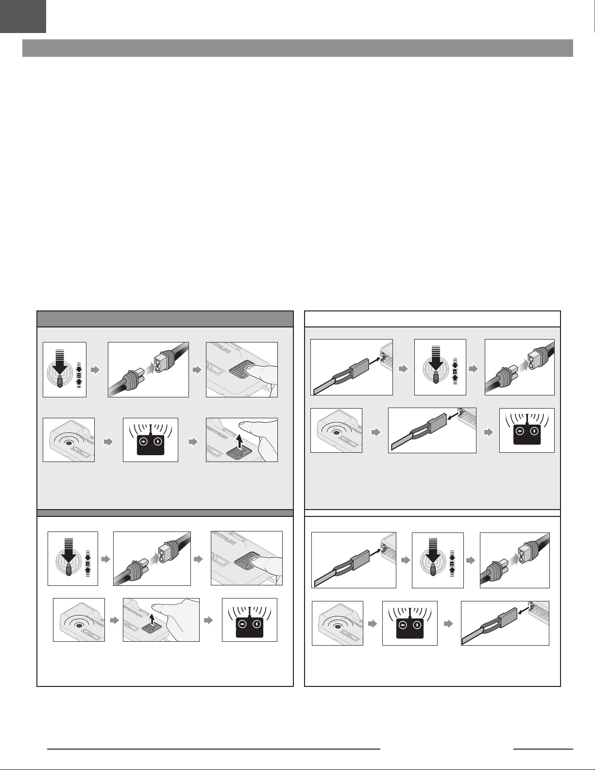
DE
Binden
Allgemeine Tipps zur Bindung
• Der mitgelieferte Empfänger wurde speziell für den Betrieb dieses Fluggeräts
programmiert. Nach dem Austausch des Empfängers sind die Anweisungen
zur ordnungsgemäßen Einrichtung dem Empfängerhandbuch zu entnehmen.
• Während des Bindens von großen Metallobjekten fern halten.
• Die Senderantenne während des Bindens nicht
direkt auf den Empfänger richten.
• Die orangefarbene LED auf dem Empfänger beginnt, schnell zu
blinken, wenn der Empfänger in den Bindungsmodus wechselt.
Binden Von Sender und Empfänger/SAFE Select ein-und auschalten
Die BNF Basic-Version dieses Flugzeugs ist mit der SAFE Select-Technologie ausgestattet, die es ermöglicht, den Grad des Flugschutzes auszuwählen. Der SAFE-Modus
beinhaltet eine Begrenzung der Schräglage und eine automatische Selbstausrichtung. Der AS3X-Modus ermöglicht dem Piloten eine direkte Reaktion auf die Steuerhebel.
SAFE Select wird während des Bindungsvorgangs aktiviert oder deaktiviert.
Ist SAFE Select deaktiviert, bendet sich das Flugzeug stets im AS3X-Modus. Ist SAFE Select aktiviert, bendet sich das Flugzeug stets im SAFE Select-Modus. Alternativ
ist es möglich, einen Schalter für den Wechsel zwischen den Modi SAFE Select und AS3X zuzuweisen.
Dank der SAFE Select-Technologie lässt sich dieses Flugzeug für Vollzeit-SAFE-Modus oder Vollzeit-AS3X-Modus kongurieren. Auch die Modusauswahl kann einem
Schalter zugewiesen werden.
WICHTIG: Vor dem Binden den Abschnitt zur Sendereinrichtung in dieser Anleitung lesen und die Sendereinrichtung abschließen, um sicherzustellen, dass der Sender für
dieses Flugzeug korrekt programmiert wurde.
WICHTIG: Die Flugsteuerungen des Senders (Höhen-, Quer- und Seitenruder) und Gastrimmung auf neutral stellen. Das Gas vor und während dem Binden auf geringe
Gaszufuhr stellen. Dieser Vorgang deniert die Failsafe-Einstellungen.
Um das Binden und den SAFE Select-Vorgang abzuschließen, lässt sich entweder der Bindungsschalter auf dem Empfängergehäuse oder der konventionelle
Bindungsstecker verwenden.
• Nach erfolgter Bindung behält der Empfänger seine Bindungseinstellungen
für den Empfänger bei, bis eine neue Bindung erfolgt.
• Wird die Kommunikation zwischen Empfänger und Sender unterbrochen,
so wird Failsafe aktiviert. Durch Failsafe wird der Gaskanal in die Position
„wenig Gas“ gebracht. Höhenruder- und Querruderkanäle bewegen sich,
um das Absacken des Flugzeug in einer Kurve aktiv zu stabilisieren.
• Treten Probleme auf, ist die Anleitung zur Fehlerbehebung zu konsultieren,
bei Bedarf hilft die Produktsupport-Abteilung von Horizon weiter.
Verwendung des Bindungsschalters Verwendung des Bindungssteckers
SAFE Select aktiviert
Mit Strom versorgenGas senken
TX an RX binden
LED
SAFE Select aktiviert: Jedes Mal, wenn der Empfänger eingeschaltet wird,
schalten die Steuerächen zweimal hin und her, mit einer kurzen Pause auf
der Neutralposition.
SAFE Select deaktiviert
Bindungsschalter betätigen und
gedrückt halten
Bindungsschalter loslassenOrangefarben blinkende
Bindungsschalter betätigenGas senken Mit Strom versorgen
SAFE Select aktiviert
BIND
Bindungsstecker installieren
LED
SAFE Select aktiviert:
schalten die Steuerächen zweimal hin und her, mit einer kurzen Pause auf
der Neutralposition.
Jedes Mal, wenn der Empfänger eingeschaltet wird,
Gas senken Mit Strom versorgen
BIND
Bindungsstecker trennen
TX an RX bindenOrangefarben blinkende
SAFE Select deaktiviert
BIND
Bindungsstecker installieren Mit Strom versorgenGas senken
Orangefarben
blinkende LED
SAFE Select deaktiviert: Jedes Mal, wenn der Empfänger eingeschaltet
wird, schalten die Steuerächen einmal hin und her.
SAFE Select lässt sich auch über die Vorwärtsprogrammierung mit kompatiblen Sendern aktivieren.
TX an RX bindenBindungsschalter loslassen
blinkende LED
SAFE Select deaktiviert: Jedes Mal, wenn der Empfänger eingeschaltet
wird, schalten die Steuerächen einmal hin und her.
32
BIND
TX an RX bindenOrangefarben
Bindungsstecker trennen
Slow Ultra Stick 1.2m
Page 33

Schalterbelegung von SAFE® Select
Stick Inputs [Hebeleingaben]
Sobald SAFE Select aktiviert ist, können Sie sich dafür entscheiden, Vollzeit im
SAFE-Modus zu iegen, oder einen Schalter zuweisen. Jeder Schalter auf jedem
Kanal zwischen 5 und 9 lässt sich auf Ihrem Sender verwenden.
Wurde das Fluggerät mit deaktiviertem SAFE Select gebunden, so verbleibt es
exklusiv im AS3X-Modus.
ACHTUNG: Alle Körperteile von Propeller fernhalten und das Fluggerät bei
versehentlicher Gasbetätigung sicher festhalten.
IMPORTANT: To be able to assign a switch, rst verify:
• Das Fluggerät wurde bei aktiviertem SAFE Select gebunden.
• Der SAFE Select-Schalter wurde einem Kanal zwischen 5
und 9 zugewiesen (Getriebe, Aux1-4) und der Verfahrweg
ist in beiden Richtungen auf 100 % eingestellt.
• Die Richtungen für Quer-, Höhen- und Seitenruder sowie
Gas sind auf normal eingestellt, nicht auf Umkehr.
• Quer-, Höhen- und Seitenruder sowie Gas sind auf 100 %
Verfahrweg eingestellt. Werden duale Raten verwendet, müssen
sich die Schalter in der Position 100 % benden.
Siehe Handbuch des Senders zu weiteren Informationen zum Zuweisen eines Schalters an
einen Kanal.
TIPP: Wird bei Verwendung eines 6-Kanal-Senders ein SAFE SAFE Select- Schalter
für das 6-Funktions-Fluggerät gewünscht, muss der SAFE Select- Schalterkanal
entweder mit Kanal 5 oder Kanal 6 des Senders geteilt werden.
Vorwärtsprogrammierung
Den SAFE Select-Kanal über die Vorwärtsprogrammierung auf Ihrem kompatiblen
Spektrum-Sender zuweisen.
Weitere Informationen zum Einstellen von SAFE Select
und Benutzen der Vorwärtsprogrammierung nden Sie ein
detailliertes Video unter folgendem Link:
https://www.youtube.com/watch?v=o-46P066cik
Zuweisen eines Schalters
1. Schalten Sie den Sender ein.
2. Schalten Sie das Fluggerät ein.
3. Beide Hebel des Senders in die unteren inneren Ecken halten und den
gewünschten Schalter 5-mal (1 Umschalten = vollständig von oben nach
unten) schnell hin- und herschalten.
4. Die Steueroberächen des Flugzeugs werden sich bewegen und so anzeigen,
dass der Schalter ausgewählt wurde.
Den Vorgang wiederholen, um einen anderen Schalter zuzuweisen oder den
aktuellen Schalter zu deaktivieren
Hebelpositionen für SAFE Select-Schalterbelegungen
Mode 1 and 2 transmitters
Assigned Switch
100%
X 5
100%
TIPP: Den Kanalmonitor zur Überprüfung der Kanalbewegung verwenden.
Dieses Beispiel eines
Kanalmonitors zeigt die
Hebelpositionen für das
Zuweisen eines Schalters,
wobei für den Schalter
Aux2 ausgewählt und ein
Verfahrweg von +/- 100
% am Schalter eingestellt
wurde .
Vorwärtsprogrammierung SAFE Select-Setup
1. Beginnen Sie mit dem an den Empfänger gebundenen Sender.
2. Schalten Sie den Sender ein.
3. Weisen Sie SAFE Select einen Schalter zu, der noch nicht durch eine
andere Funktion belegt ist. Verwenden Sie einen beliebigen offenen
Kanal zwischen 5 und 9 (Getriebe, Aux1-4).
4. Schalter H (Gasabschaltung) einstellen, um unbeabsichtigten
Motorbetrieb zu verhindern.
DX-Serie,
NX Serie,
iX Serie
5. Schalten Sie das Fluggerät ein. Auf dem Hauptbildschirm Ihres
Senders erscheint eine Signalleiste, wenn Telemetrieinformationen
eingehen.
6. Auf FUNCTION LIST [Funktionsliste] (Model Setup) [Modell-Setup]
gehen
7. Wählen Sie Vorwärtsprogrammierung; Wählen Sie Kreiseleinstellungen,
Wählen Sie SAFE Select um das Menü aufzurufen.
8. SAFE Select Kanal einstellen; Auf den Kanal, den Sie für SAFE Select
gewählt haben.
9. Wählen Sie AS3X und SAFE On oder Off wie für jede Schaltposition
gewünscht.
-100
THR
100
AIL
-100
ELE
Monitor
-100
-100
RUD
GER
-100
AX1
+/-100
AX2
-100
AX3
-100
AX4
DE
33
Page 34

DE
Integrierte Geschwindigkeitsregler-Telemetrie
Dieses Flugzeug ist im Geschwindigkeitsregler und Empfänger mit TelemetrieTechnologie ausgestattet, die Informationen wie Motordrehzahl, Spannung,
Motorstrom, Gaseinstellung (%) und FET-Temperatur (Geschwindigkeitsregler)
liefern kann.
Weitere Informationen zu kompatiblen Sendern, Firmware-Aktualisierungen und
zur Telemetrie-Technologie auf Ihrem Sender finden Sie unter www.SpektrumRC.
com.
Steuerrichtungstests
Den Sender einschalten und den Akku anschließen. Den Sender zum Steuern der
Querruder-, Höhenruder- und Seitenrudersteuerungen verwenden. Beim Prüfen der
Steuerungsrichtungen das Fluggerät von hinten ansehen.
Dieses Modell hat eine eingebaute Querruder-Seitenruder-Mischung, bei
Auslenkung der Querruder wird das Seitenruder bewegt.
DX-Serie,
NX Serie,
iX Serie
Telemetrie-Konguration
1. Beginnen Sie mit dem an den Empfänger gebundenen Sender.
2. Schalten Sie den Sender ein.
3. Schalter H (Gasabschaltung) einstellen, um unbeabsichtigten
Motorbetrieb zu verhindern.
4. Schalten Sie das Fluggerät ein. Auf dem Hauptbildschirm Ihres
Senders erscheint eine Signalleiste, wenn Telemetrieinformationen
eingehen.
5. Auf FUNCTION LIST [Funktionsliste] (Model Setup) [Modell-Setup]
gehen
6. TELEMETRY [Telemetrie]; Smart ESC [Smart-
Geschwindigkeitsregler] auswählen
7. Total Cells [Gesamtzahl Zellen] einstellen: 3
8. LVC Alarm einstellen: 3,4V Alarm einstellen; Voice/Vibe [Voice/
Vibration]
9. Pole count [Polzahl] einstellen; 14 Pole
Sendersteuerung Reaktion der Steueroberächen
Höhenruder
1. Den Höhenruder-Hebel zurückziehen. Die Höhenruder sollten sich nach oben
bewegen, sodass das Fluggerät steigt.
2. Den Höhenruder-Hebel nach vorne drücken. Die Höhenruder sollte sich nach
unten bewegen, sodass das Fluggerät sinkt.
Querruder
1. Den Querruder-Hebel nach rechts bewegen. Das rechte Querruder sollte sich
nach oben und das linke Querruder nach unten bewegen, sodass sich das
Fluggerät nach rechts neigt.
2. Den Querruder-Hebel nach links bewegen. Das linke Querruder sollte sich
nach oben und das rechte Querruder nach unten bewegen, sodass sich das
Fluggerät nach links neigt.
Seitenruder
1. Den Seitenruder-Hebel nach rechts bewegen. Das Seitenruder sollte sich nach
rechts bewegen, sodass das Fluggerät nach rechts giert.
2. Den Seitenruder-Hebel nach links bewegen. Das Seitenruder sollte sich nach
links bewegen, sodass das Flugzeug nach links giert.
HöhenruderQuerruderSeitenruder
34
Slow Ultra Stick 1.2m
Page 35
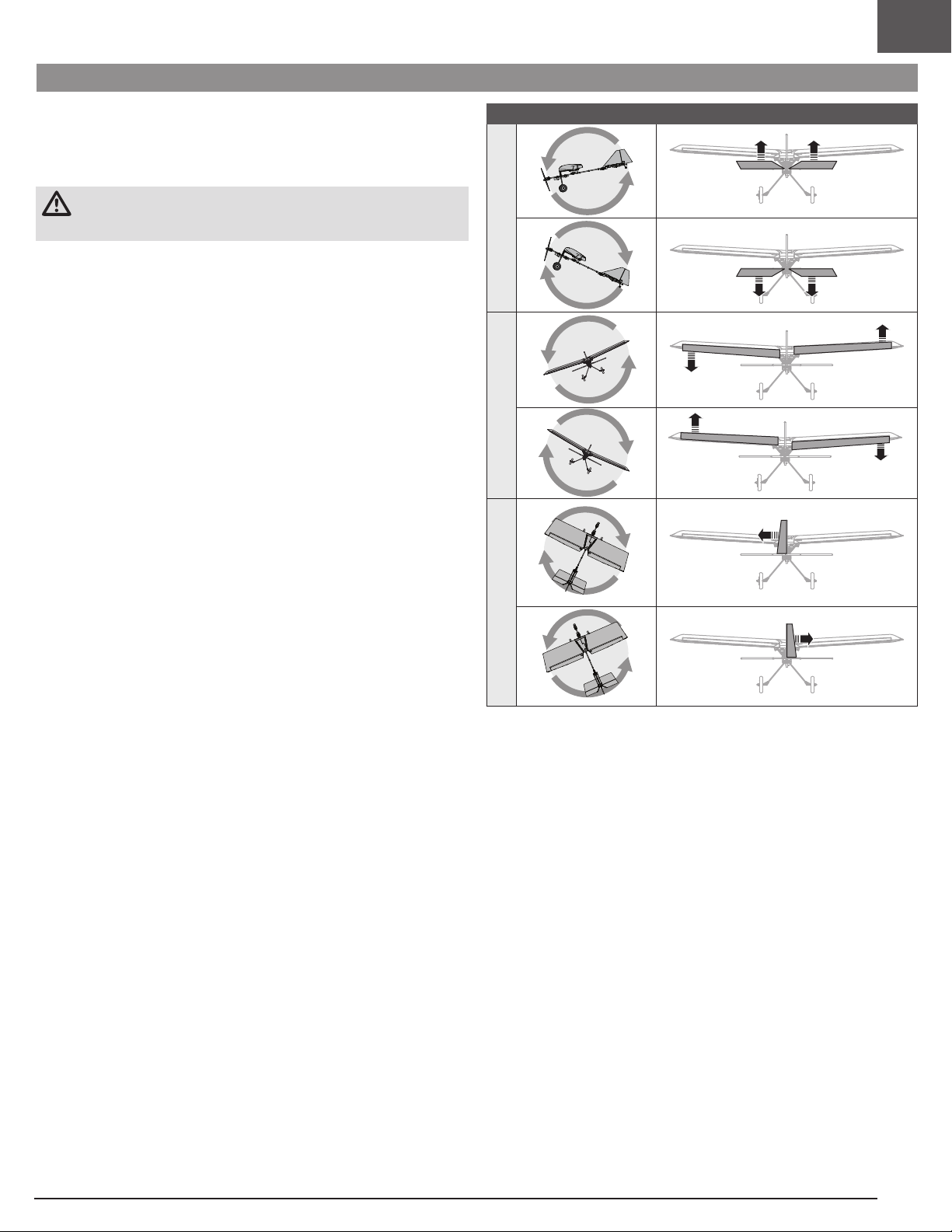
AS3X-Kontrolle Lenktest
DE
Dieser Test stellt sicher, dass das AS3X®-Steuersystem ordnungsgemäß
funktioniert. Das Flugzeug zusammenbauen und Sender am Empfänger binden, ehe
dieser Test durchgeführt wird.
1. Gashebel bis kurz über 25% heben, dann Gashebel senken, um die AS3XTechnologie zu aktivieren.
ACHTUNG: Alle Körperteile, Haare und locker getragene Kleidung von dem
sich drehenden Propeller fernhalten, da sich diese im Propeller verfangen
können.
2. Das gesamte Flugzeug wie abgebildet bewegen und sicherstellen, dass sich
die Steueroberächen in die laut der Grak ausgewiesenen Richtung bewegen.
Reagieren die Steueroberächen nicht wie abgebildet, das Flugzeug nicht
iegen. Siehe Handbuch des Empfängers zu weiteren Informationen.
Die Steueroberächen können sich schnell bewegen, sobald das AS3X-System
aktiv ist. Das ist normal. AS3X bleibt bis zur Trennung des Akkus aktiv.
Aufgrund unterschiedlicher Auswirkungen von Drehmoment, Auftrieb und
Luftwiderstand erfordern einige Flugzeuge Trimmänderungen mit unterschiedlichen
Geschwindigkeiten und Gaseinstellungen. Mischungen werden vorab in den
Empfänger geladen, um diese Änderungen zu kompensieren. Die Mischungen
werden aktiv, wenn das Gas zum ersten Mal über 25 % angehoben wird. Die Ruder
können bei unterschiedlichen Gaseinstellungen nach dem ersten Anheben des
Gases leicht versetzt sein. Das Trimmen des Flugzeugs im Flug sollte mit 80-100%
Gas erfolgen, um beste Ergebnisse zu erzielen.
Flugzeug bewegung AS3X Reaktion
Höhenruder
QuerruderSeitenruder
35
Page 36
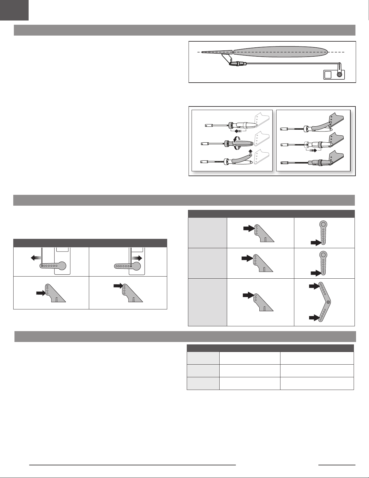
DE
Zentrieren der Steuerächen und Anpassen eines Gabelkopfs
IMPORTANT: Perform the Control Direction Test before performing control surface
centering.
While SAFE is inactive, mechanically center the control surfaces.
IMPORTANT: Correct operation of the SAFE system requires sub-trim and trim at 0.
After binding a transmitter to the receiver, set the trims and sub-trims to 0, ensure
the servo arms are in the correct positions, then adjust the linkages to center the
control surfaces.
Gabelkopf entfernen
1. Das Halterungsrohr vom Gabelkopf schieben.
2. Den Gabelkopf vorsichtig spreizen und den Gabelkopfbolzen aus dem
Steuerhorn entfernen.
Den Gabelkopf anpassen
3. Den Gabelkopf drehen, um die Länge des Gestänges anzupassen.
Den Gabelkopf wieder anbringen
4. Den Gabelkopf vorsichtig spreizen und den Gabelkopfbolzen in die spezielle
Bohrung im Steuerhorn einführen.
5. Das Halterungsrohr bewegen, um den Gabelkopf am Steuerhorn zu sichern.
1.
2.
3.
4.
5.
6.
Horn- und Servoarm-Einstellungen
Die Tabelle rechts zeigt die werkseitigen Einstellungen der Steuerhörner und
Servoarme. Das Fluggerät mit den Werkseinstellungen iegen, ehe Änderungen
vorgenommen werden.
Größerer Ruderausschlag Geringerer Ruderausschlag
Duale Geschwindigkeit
Den Sender programmieren, um die Geschwindigkeiten und Ruderausschläge auf
die angegebenen Werte einzurichten. Diese Werte wurden getestet und sind ein
guter Ausgangspunkt, um erfolgreiche Flüge zu erreichen.
Höhenruder
Seitenruder
Querruder
Querruder
Höhenruder
Seitenruder
Steuerhörner Servoarme
Hohe Geschwindigkeit Niedrige Geschwindigkeit
p = 12mm
q = 12mm
p = 15mm
q = 15mm
= 25mm
= 25mm
p = 8mm
q = 8mm
p = 11mm
q = 11mm
= 15mm
= 15mm
36
Slow Ultra Stick 1.2m
Page 37

Der Schwerpunkt (CG)
Die CG-Position wird von der Vorderkante des Flügels gemessen. Die Position
des Schwerpunkts wurde mit dem empfohlenen 3S 1300mAh Li-Po-Akku
(SPMX133S30) bestimmt, der an der Vorderkante der Akkuhalterung montiert
wurde. Den Akku bei Bedarf nach vorn oder hinten ausrichten, um den korrekten
Schwerpunkt zu erreichen.
ACHTUNG: Akkus einsetzen, aber den Geschwindigkeitsregler während der
Prüfung des CGs nicht aktivieren. Dies kann Verletzungen verursachen.
DE
115mm +/-5
hinter der Vorderkante.
Tipps für das Fliegen mit Safe Select
Wenn das Flugzeug im SAFE Select-Modus iegt, kehrt es in den Horizontalug
zurück, wenn sich die Querruder- und Höhenrudersteuerung auf Neutral benden.
Mit der Querruder- oder Höhenrudersteuerung kann bewirkt werden, dass das
Flugzeug sich neigt, steigt oder in einen Sturzug übergeht. Zudem bestimmt die
Intensität mit der Steuerhebel bewegt wird die Fluglage des Flugzeugs. Die volle
Kontrolle zu behalten, fordert die voreingestellten Neigungs- und Rollgrenzen des
Flugzeugs heraus, führt aber nicht zu einem Überschreiten dieser Winkel.
Beim Fliegen mit SAFE Select wird der Steuerhebel normalerweise in ausgelenkter
Position gehalten, bei moderater Eingabe beim Querruder in Kurven. Um mit
SAFE Select reibungslos zu iegen, häuge Steuerungsänderungen vermeiden
und das Korrigieren kleinerer Abweichungen möglichst vermeiden. Durchdachte
Steuereingaben geben dem Flugzug den Befehl, in einem bestimmten Winkel zu
iegen und das Modell nimmt alle Anpassungen vor, um die Fluglage zu halten.
Beim Fliegen mit SAFE Select, sorgt das Gas dafür, dass das Flugzeug steigt oder
sinkt. Vollgas führt dazu, dass das Flugzeug leicht die Nase anhebt und steigt.
Mittleres Gas hält das Flugzeug in der jeweiligen Flughöhe. Geringes Gas führt
dazu, dass das Flugzeug mit der Nase nach unten langsam sinkt.
Die Höhen- und Querrudersteuerung auf Neutral stellen, und dann vom SAFE
Select-Modus in den AS3X-Modus wechseln. Wird beim Umschalten in den AS3XModus die Steuerung nicht neutralisiert, sind die für den SAFE Select-Modus
verwendeten Steuereingänge für den AS3X-Modus zu groß und das Flugzeug
reagiert sofort.
Trimmung während des Fluges
Das Fluggerät beim ersten Flug für Horizontalug mit Gashebel auf 80-100%,
mit eingefahrenen Klappen und eingefahrenem Fahrwerk trimmen (DIES WIRD
ENTFERNT). Zum Erreichen des geraden Horizontalugs des Fluggeräts kleine
Trimmkorrekturen mit den Trimmschaltern des Senders vornehmen..
Unterschiede zwischen den Modi SAFE Select und AS3X
Dieser Abschnitt ist grundsätzlich präzise, berücksichtigt aber nicht die
Fluggeschwindigkeit, den Ladezustand der Batterie und andere einschränkende
Faktoren.
SAFE Select AS3X
Steuerhebel wird
in Neutralposition
gebracht
Geringfügige
Steuereingaben
Volle Steuerung
Steuereingabe
Gas
3 Sekunden
Flugzeug richtet sich selbst aus
Flugzeug wird in eine moderate
Schräglage bzw. Neigung
bewegt, wo es verbleibt.
Flugzeug wird bis zu den
vorgegebenen Grenzen in
Schräglage bzw. Neigung
bewegt, wo es verbleibt.
Vollgas: Ansteigen
Neutral: Horizontalug
Geringes Gas: Sinken mit der
Nase nach unten
Flugzeug behält
aktuelle Position bei
Weiterhin langsames
Neigen und Rollen
des Flugzeugs
Weiterhin schnelles
Neigen und Rollen
des Flugzeugs
Gas beeinträchtigt die
Flugreaktion nicht.
Nach erfolgter Einstellung der Trimmung berühren Sie die Steuerknüppel 3
Sekunden lang nicht. Dadurch erhält der Empfänger die Informationen über die zur
Optimierung der AS3X-Leistung geeigneten Einstellungen.
Wenn Sie dies nicht tun, kann die Flugleistung beeinträchtigt werden.
37
Page 38

DE
Wahlweise Zwei-Servo-Querrudereinstellung
1. Die Tragäche vom Fluggerät entfernen.
2. Die Schraube des Servoarms und den eingebauten Servoarm entfernen.
3. Der Servoarm wurde vom Z-Bogen der beiden Schubstangen entfernt.
4. Entfernen Sie die 2 Schrauben, mit denen das Servo an der Tragäche befestigt
ist.
5. Bringen Sie das Servo wieder links von der Servotasche an und richten Sie es
an den linken Positionsschraubenlöchern aus.
6. Führen Sie das Servokabel und den Stecker aus der Servotasche und sichern
Sie das Servo mit den 2 Schrauben.
7. Montieren Sie ein zweites Querruderservo (SPMSA345SL, nicht im
Lieferumfang enthalten) in der rechten Servoposition in der Servotasche.
8. Führen Sie den Servostecker und den Steckverbinder in den rechten Kanal
ein, der aus der Servotasche austritt, und richten Sie die Schrauben mit den
Schraubenlöchern aus und befestigen Sie diese.
9. Schließen Sie das rechte Servo an Kanal 2 und das linke Servo an Kanal 6 des
Empfängers an.
10. Ändern Sie in den Systemeinstellungen Ihres Senders den Flugzeugtyp auf
Dual Aileron.
11. Schließen Sie einen Akku an das Flugzeug an und schalten Sie das Flugzeug
ein, um die Servos auszurichten.
12. Verbinden Sie den Z-Bogen des Steuergestänges mit dem äußersten Loch des
neuen Servohorns (EFL0370, erforderlich und nicht im Lieferumfang enthalten).
Wiederholen Sie den Vorgang für das andere Servohorn.
13. Montieren Sie das Servohorn so nah wie möglich am 90-Grad-Winkel auf das
Servo und sichern Sie es mit einer Schraube.
14. Setzen Sie das Gabelkopfende des neuen Gestänges in das äußerste Loch des
Querrudersteuerhorns ein.
15. Vergewissern Sie sich, dass die Querrudersteuerächen mittig ausgerichtet
sind; stellen Sie gegebenenfalls die Schubstange mechanisch ein, um das
Querruder zu zentrieren.
16. Montieren Sie die Tragäche am Rumpf.
Querruder-Servoarm
Querruder-Steuerhorn
Halterungsrohr
Gestänge Gabelkopf
Computergestützte Senderkonguration
Die gesamte Senderprogrammierung mit einem leeren ACRO-Modell (eine
Zurücksetzung des Modells durchführen) beginnen, dann das Modell benennen.
2-Positionen-Schalter 3-Positionen-Schalter
Duale Geschwindigkeit
einstellen auf
Servoverfahrweg
einstellen auf
Gasabschaltung auf -100%
‡
DX6e
DX6 ‡ (Gen2)
DX7‡ (Gen2)
‡
NX6
DX8e
DX8 (Gen2)
DX9
DX10t
DX18
DX20
†
iX12
†
iX20
NX6
NX8
NX10
1. Auf SYSTEM SETUP [Systemkonguration] gehen (Model
Utilities) [Modell-Dienstprogramme]†
2. MODEL TYPE [Modelltyp] einstellen: AIRPLANE [Flugzeug]
3. AIRCRAFT TYPE [Flugzeugtyp] einstellen: Model Setup
(Modellkonguration), Aircraft Type (Fluggerättyp)†:
TRAGFLÄCHE: Doppeltes Querruder
HOCH 100 %
NIEDRIG 70% NIEDRIG 50%
100%
HOCH 100 %
MITTIG 70%
38
Slow Ultra Stick 1.2m
Page 39

Nach dem Flug
DE
1. Den Flug-Akku vom Geschwindigkeitsregler trennen (für die Sicherheit und
die Lebensdauer des Akkus erforderlich).
2. Sender ausschalten.
3. Den Flug-Akku vom Flugzeug entfernen.
4. Alle beschädigten Teile reparieren oder ersetzen.
Motorwartung
ACHTUNG: Vor der Motorwartung immer den Flugakku trennen.
Zerlegen
1. Den Spinner (A), die Schraube (B), die Unterlegscheibe (C), die
Propellermutter (D) und den Propeller (E) entfernen.
2. Die 4 Schrauben (F) von der Propellerwelle (G) entfernen.
3. Die Propellerwelle von der Motorwelle entfernen.
4. Die 2 Schrauben (H) von der Motorhalterung (I) und dem Rumpf entfernen.
5. Die Motordrähte von den Drähten des Geschwindigkeitsreglers trennen.
Zusammenbau
Alles in umgekehrter Reihenfolge wieder zusammenbauen.
• Die Aderfarben der Motordrähte korrekt mit den Drähten des
Geschwindigkeitsreglers verbinden.
• Den Propeller montieren, dabei müssen die eingeprägten Größennummern
(11 x 5,5) nach vorn zeigen.
• Die Propellermutter mit einem 10mm Schraubenschlüssel festziehen.
• Schieben Sie den Gummispinner wieder auf die Kunststoffhalterung des
Spinners.
5. Den Flug-Akku getrennt vom Flugzeug lagern und den Akku-Ladezustand
überwachen.
6. Mit Blick auf die Planung zukünftiger Flüge, die Flugbedingungen und
Flugergebnisse notieren.
E
H
I
D
B
G
F
C
Verdrahtung nicht
A
abgebildet
Warten des Servos
Steueräche Ersatzservo Beschreibung
Querruder
SPMSA345SL A345SL 9g Sub-Micro-ServoHöhenruder
Seitenruder
AS3X Fehlerbehebung
Problem Mögliche Ursache Lösung
Beschädigter Propeller oder Spinner Propeller oder Spinner ersetzen
Propeller ausbalancieren. Zu weiteren Informationen das Video von John Redman zum
Ausbalancieren des Propellers unter www.horizonhobby.com ansehen
Wird die Trimmung um mehr als 8 Klicks angepasst, die Schraube im Gestängeanker am Servo
lösen und das Gestänge verschieben, dann die Schraube wieder anziehen.
Gashebel in niedrigster Position. Akku trennen, dann Akku wieder anschließen und Flugzeug für
5Sekunden still halten
NICHT iegen. Product Support kontaktieren, um eine Lösung zu nden.
Oszillation
Ungleichmäßige
Flugleistung
Falsche Reaktion auf den
AS3X-Steuerrichtungstest
Propeller im Ungleichgewicht
Motorvibrationen Bauteile ersetzen oder alle Bauteile korrekt ausrichten und Befestiger festziehen, je nach Bedarf
Loser Empfänger Empfänger im Rumpf ausrichten und sichern
Lose Flugzeugsteuerungen Bauteile (Servo, Arm, Gestänge, Horn und Steueroberäche) festziehen oder anderweitig sichern
Verschlissene Bauteile Verschlissene Bauteile (insbesondere Propeller, Spinner oder Servo) ersetzen
Ungleichmäßige Servobewegungen Servo ersetzen
Trimmung ist nicht auf Neutral
Ersatztrimmung ist nicht auf Neutral Keine Ersatztrimmung zugelassen. Servogestänge anpassen
Flugzeug wurde dem Verbinden des Akkus
nicht für 5Sekunden still gehalten
Falsche Richtungseinstellungen im
Empfänger, was zu Abstürzen führen kann
39
Page 40

DE
Fehlerbehebung
Problem Mögliche Ursache Lösung
Die Steuerungen mit Gashebel und Gastrimmung auf niedrigster Einstellung
zurücksetzen
Beschädigte Bauteile ersetzen
Eingeschalteten Sender vom Flugzeug wegbewegen, Flug-Akku vom Flugzeug
trennen und wieder anschließen
Flugzeug und Sender an eine andere Stelle bringen und das Binden erneut versuchen
Bindungsstecker im Bindungsanschluss montieren und Flugzeug am Sender binden
Sender ausschalten und den Bindungsvorgang wiederholen. Bindungsschalter oder
-taster des Senders halten, bis der Empfänger gebunden ist
Eingeschalteten Sender vom Flugzeug wegbewegen, Flug-Akku vom Flugzeug
trennen und wieder anschließen
Flugzeug und Sender an eine andere Stelle bringen und das Binden erneut versuchen
Den Sender am Flugzeug binden und den Bindungsstecker entfernen, ehe die
Stromzufuhr ein- und ausgeschaltet wird
Korrekten Modellspeicher auf dem Sender wählen
Flugzeug an den Sender binden
Flugzeug reagiert nicht
auf Gas, aber auf alle
anderen Steuerungen
Zusätzliche Geräusche
am Propeller oder
zusätzliche Vibrationen
Flugzeit reduziert
oder Flugzeug
untermotorisiert
Flugzeug bindet
(während des Bindens)
nicht am Sender
Flugzeug verbindet
sich (während des
Bindens) nicht mit dem
Sender
Gas nicht im Leerlauf und/oder Gastrimmung zu hoch
Verfahrweg des Gasservo liegt unter 100% Sicherstellen, dass Verfahrweg des Gasservos 100% oder höher ist
Gaskanal ist umgekehrt Gaskanal auf dem Sender umkehren
Motor vom Geschwindigkeitsregler getrennt Sicherstellen, dass der Motor mit dem Geschwindigkeitsregler verbunden ist
Beschädigter Propeller und Spinner, Klemmbuchse oder
Motor
Propeller ist nicht in Balance Propeller ausbalancieren oder ersetzen
Propellermutter zu locker Propellermutter festziehen
Ladezustand des Akkus ist niedrig Flug-Akku komplett auaden
Propeller verkehrt herum montiert Propeller mit Zahlen nach vorne weisend montieren
Flug-Akku beschädigt Flug-Akku ersetzen und Anweisungen zum Flug-Akku befolgen
Flugbedingungen können zu kalt sein Sicherstellen, dass der Akku vor der Verwendung warm ist
Akku-Kapazität für die Flugbedingungen zu gering Akku ersetzen oder einen Akku mit höherer Kapazität verwenden
Sender während des Bindungsvorgangs zu nah am
Flugzeug
Flugzeug oder Sender zu nah an einem großen
Metallobjekt, einer drahtlosen Quelle oder einem anderen
Sender
Der Bindungsstecker ist nicht richtig im
Bindungsanschluss montiert
Ladezustand des Flug-Akkus/Sender-Akkus zu niedrig Akkus ersetzen/auaden
Bindungsschalter oder -taster während des
Bindungsvorgangs nicht lange genug gehalten
Sender während des Verbindungsvorgangs zu nah am
Flugzeug
Flugzeug oder Sender zu nah an einem großen
Metallobjekt, einer drahtlosen Quelle oder einem anderen
Sender
Bindungsstecker verbleibt im Bindungsanschluss montiert
Flugzeug an einem anderen Modellspeicher gebunden
(nur ModelMatchTM-Funkgeräte)
Ladezustand des Flug-Akkus/Sender-Akkus zu niedrig Akkus ersetzen/auaden
Der Sender kann an ein anderes Flugzeug mit einem
anderen DSM-Protokoll gebunden sein
40
Slow Ultra Stick 1.2m
Page 41

Ersatzteile Optionale Teile
DE
Teile-Nr. Beschreibung
EFL0351 Rechter Flügel: Slow Ultra Stick
EFL0352 Linker Flügel: Slow Ultra Stick
EFL0353 Flügelverbindung: Slow Ultra Stick
EFL0354 Steckungsrohr: Slow Ultra Stick
EFL0355 Daumenschraubensatz: Slow Ultra Stick
EFL0356 Vordere Flügelstütze: Slow Ultra Stick
EFL0357 Hintere Flügelstütze: Slow Ultra Stick
EFL0358 Halterung: Slow Ultra Stick
EFL0359 Motorhalterung: Slow Ultra Stick
EFL0360 Gummispinner: Slow Ultra Stick
EFL0361 Propelleradapter: Slow Ultra Stick
EFL0362 Fahrwerksatz: Slow Ultra Stick
EFL0363 Steuerhornsatz: Slow Ultra Stick
EFL0364 Steuerkettensatz: Slow Ultra Stick
EFL0365 Kabelhalterungsset: Slow Ultra Stick
EFL0366 Rumpf: Slow Ultra Stick
EFL0367 Rumpfbefestiger: Slow Ultra Stick
EFL0368 Seitenleitwerk: Slow Ultra Stick
EFL0369 Höhenleitwerk: Slow Ultra Stick
EFL0370 Servoarm-Satz: Slow Ultra Stick
EFL0371 Decalsatz: Slow Ultra Stick
EFL0372 Hardwaresatz: Slow Ultra Stick
EFLP1155 Propeller: 11 x 5,5
SPMSA345SL A345SL 9g Sub-Micro-Servo; 60mm L
SPMXAE30D Avian 30A Bürstenloser Smart-Geschwindigkeitsregler
SPMXAM2800 Bürstenloser Motor: 3513-1100Kv
SPMAR630 AR630 DSMX 6-Kanal AS3X & SAFE Empfänger
Empfohlene Artikel
Teile-Nr. Beschreibung
SPMR6655 Nur DX6e-Sender mit 6 Kanälen
SPMX133S30 1300mAh 3S 11,1V Smart G2 30C;
SPMXC2050 Smart S155 G2 1x55W Wechselstrom-Ladegerät
Teile-Nr. Beschreibung
SPMR8105 Nur NX8e-Sender mit 8 Kanälen
SPMR6775 Nur NX66-Kanal-Sender
SPMR8200 Nur NX8-Sender mit 8 Kanälen
SPMXC2080 Smart S1100 G2 Wechselstrom-Ladegerät, 1x100W
SPMX22003S30 2200mAh 3S 11,1V Smart 30C; IC3
SPMX223S30 2200mAh 3S 11,1V Smart G2 30C;
APC11055E Elektrischer Propeller, 11 x 5,5E
SPMSA345SL A345 9g Sub-Micro Digital Servo; 60mm Leitung
EFL0370 Servoarm-Satz: Slow Ultra Stick
Hardware
Menge Standort Beschreibung
4 M3 x 6mm Maschinenschraube
1 M2x6mm Maschinenschraube
1 M3 x 22mm Daumenschrauben
3 2,3x4,5mm Blechschraube
4 2x8mm Blechschraube
M3 x 22mm Maschinendaumen-
2
schraube
1 M3 x 6mm Maschinenschraube
1 M6 Propellerschraubenmutter
4 M2x7mm Maschinenschraube
M2x14mm
1
Maschinenschraube
M2x14mm
1
Maschinenschraube
M2x14mm
1
Maschinenschraube
M2x14mm
1
Maschinenschraube
1 M2x6mm Maschinenschraube
6 2x8mm Blechschraube
M2x14mm
4
Maschinenschraube
1 12.8mm x 500mm Steckungsrohr
Durchmesser 85mm, Breite
2
17mm, Achse 3mm
Durchmesser 21mm, Breite
1
7mm, Achse 1,3mm
Zur Sicherung des Motors an der
Motorhalterung
Zur Sicherung der Geschwindigkeitsreglerhalterung am Rumpf
Zur Sicherung des horizontalen
Stabilisators am Rumpf
Zur Sicherung des Servoarms am
Servo
Zur Sicherung des Steuerhorns an
der Steueräche
Zur Sicherung der Tragäche am
Rumpf
Zur Sicherung der Spinner-Haltescheibe
Zur Sicherung des Propellers an
der Propellerwelle
Zur Sicherung des Propelleradapters am Motor
Zur Sicherung der Motorhalterung
am Rumpf
Zur Sicherung der Akkuhalterung
am Rumpf
Zur Sicherung der
Tragächenhalterung am Rumpf
Zur Sicherung der hinteren
Tragächenhalterung am Rumpf
Zur Sicherung der
Empfängerhalterung am Rumpf.
Zur Sicherung der Servos am
Rumpf
Zur Sicherung der beiden
Rumpfhälften miteinander
Hauptrad
Spornrad
41
Page 42

DE
Haftungsbeschränkung
Warnung
Ein ferngesteuertes Modell ist kein Spielzeug. Es kann, wenn es falsch eingesetzt
wird, zu erheblichen Verletzungen bei Lebewesen und Beschädigungen an Sachgütern
führen. Betreiben Sie Ihr RC-Modell nur auf freien Plätzen und beachten Sie alle
Hinweise der Bedienungsanleitung des Modells wie auch der Fernsteuerung.
Garantiezeitraum
Exklusive Garantie Horizon Hobby LLC (Horizon) garantiert, dass dasgekaufte Produkt
frei von Material- und Montagefehlern ist. Der Garantiezeitraum entspricht den
gesetzlichen Bestimmung des Landes, in dem das Produkt erworben wurde. In
Deutschland beträgt der Garantiezeitraum 6 Monate und der Gewährleistungszeitraum
18 Monate nach dem Garantiezeitraum.
Einschränkungen der Garantie
(a) Die Garantie wird nur dem Erstkäufer (Käufer) gewährt und kann nicht übertragen
werden. Der Anspruch des Käufers besteht in der Reparatur oder dem Tausch im
Rahmen dieser Garantie. Die Garantie erstreckt sich ausschließlich auf Produkte,
die bei einem autorisierten Horizon Händler erworben wurden. Verkäufe an
dritte werden von dieser Garantie nicht gedeckt. Garantieansprüche werden nur
angenommen, wenn ein gültiger Kaufnachweis erbracht wird. Horizon behält sich
das Recht vor, diese Garantiebestimmungen ohne Ankündigung zu ändern oder
modifizieren und widerruft dann bestehende Garantiebestimmungen.
(b) Horizon übernimmt keine Garantie für die Verkaufbarkeit des Produktes, die
Fähigkeiten und die Fitness des Verbrauchers für einen bestimmten Einsatzzweck
des Produktes. Der Käufer allein ist dafür verantwortlich, zu prüfen, ob das Produkt
seinen Fähigkeiten und dem vorgesehenen Einsatzzweck entspricht.
(c) Ansprüche des Käufers ¬ Es liegt ausschließlich im Ermessen von Horizon, ob das
Produkt, bei dem ein Garantiefall festgestellt wurde, repariert oder ausgetauscht
wird. Dies sind die exklusiven Ansprüche des Käufers, wenn ein Defekt festgestellt
wird.
Horizon behält sich vor, alle eingesetzten Komponenten zu prüfen, die in den
Garantiefall einbezogen werden können. Die Entscheidung zur Reparatur oder zum
Austausch liegt nur bei Horizon. Die Garantie schließt kosmetische Defekte oder
Defekte, hervorgerufen durch höhere Gewalt, falsche Behandlung des Produktes,
falscher Einsatz des Produktes, kommerziellen Einsatz oder Modifikationen
irgendwelcher Art aus.
Die Garantie schließt Schäden, die durch falschen Einbau, falsche Handhabung,
Unfälle, Betrieb, Service oder Reparaturversuche, die nicht von Horizon ausgeführt
wurden aus.
Ausgeschlossen sind auch Fälle die bedingt durch (vii) eine Nutzung sind, die
gegen geltendes Recht, Gesetze oder Regularien verstoßen haben. Rücksendungen
durch den Käufer direkt an Horizon oder eine seiner Landesvertretung bedürfen der
Schriftform.
Schadensbeschränkung
Horizon ist nicht für direkte oder indirekte Folgeschäden, Einkommensausfälle oder
kommerzielle Verluste, die in irgendeinem Zusammenhang mit dem Produkt stehen
verantwortlich, unabhängig ab ein Anspruch im Zusammenhang mit einem Vertrag, der
Garantie oder der Gewährleistung erhoben werden. Horizon wird darüber hinaus keine
Ansprüche aus einem Garantiefall akzeptieren, die über den individuellen Wert des
Produktes hinaus gehen. Horizon hat keinen Einfluss auf den Einbau, die Verwendung
oder die Wartung des Produktes oder etwaiger Produktkombinationen, die vom
Käufer gewählt werden. Horizon übernimmt keine Garantie und akzeptiert keine
Ansprüche für in der folge auftretende Verletzungen oder Beschädigungen. Mit der
Verwendung und dem Einbau des Produktes akzeptiert der Käufer alle aufgeführten
Garantiebestimmungen ohne Einschränkungen und Vorbehalte.
Wenn Sie als Käufer nicht bereit sind, diese Bestimmungen im Zusammenhang mit
der Benutzung des Produktes zu akzeptieren, werden Sie gebeten, dass Produkt
in unbenutztem Zustand in der Originalverpackung vollständig bei dem Verkäufer
zurückzugeben.
Sicherheitshinweise
Dieses ist ein hochwertiges Hobby Produkt und kein Spielzeug. Es muss mit Vorsicht
und Umsicht eingesetzt werden und erfordert einige mechanische wie auch mentale
Fähigkeiten. Ein Versagen, das Produkt sicher und umsichtig zu betreiben kann zu
Verletzungen von Lebewesen und Sachbeschädigungen erheblichen Ausmaßes
führen. Dieses Produkt ist nicht für den Gebrauch durch Kinder ohne die Aufsicht
eines Erziehungsberechtigten vorgesehen. Die Anleitung enthält Sicherheitshinweise
und Vorschriften sowie Hinweise für die Wartung und den Betrieb des Produktes.
Es ist unabdingbar, diese Hinweise vor der ersten Inbetriebnahme zu lesen und zu
verstehen. Nur so kann der falsche Umgang verhindert und Unfälle mit Verletzungen
und Beschädigungen vermieden werden.
Fragen, Hilfe und Reparaturen
Ihr lokaler Fachhändler und die Verkaufstelle können eine Garantiebeurteilung ohne
Rücksprache mit Horizon nicht durchführen. Dies gilt auch für Garantiereparaturen.
Deshalb kontaktieren Sie in einem solchen Fall den Händler, der sich mit Horizon kurz
schließen wird, um eine sachgerechte Entscheidung zu fällen, die Ihnen schnellst
möglich hilft.
Wartung und Reparatur
Muss Ihr Produkt gewartet oder repariert werden, wenden Sie sich entweder an Ihren
Fachhändler oder direkt an Horizon.
Rücksendungen / Reparaturen werden nur mit einer von Horizon vergebenen
RMA Nummer bearbeitet. Diese Nummer erhalten Sie oder ihr Fachhändler vom
technischen Service. Mehr Informationen dazu erhalten Sie im Serviceportal unter
www. Horizonhobby.de oder telefonisch bei dem technischen Service von Horizon.
Packen Sie das Produkt sorgfältig ein. Beachten Sie, dass der Originalkarton in der
Regel nicht ausreicht, um beim Versand nicht beschädigt zu werden. Verwenden
Sie einen Paketdienstleister mit einer Tracking Funktion und Versicherung, da
Horizon bis zur Annahme keine Verantwortung für den Versand des Produktes
übernimmt. Bitte legen Sie dem Produkt einen Kaufbeleg bei, sowie eine ausführliche
Fehlerbeschreibung und eine Liste aller eingesendeten Einzelkomponenten. Weiterhin
benötigen wir die vollständige Adresse, eine Telefonnummer für Rückfragen, sowie
eine Email Adresse.
Garantie und Reparaturen
Garantieanfragen werden nur bearbeitet, wenn ein Originalkaufbeleg von einem
autorisierten Fachhändler beiliegt, aus dem der Käufer und das Kaufdatum hervorgeht.
Sollte sich ein Garantiefall bestätigen wird das Produkt repariert oder ersetzt. Diese
Entscheidung obliegt einzig Horizon Hobby.
Kostenpichtige Reparaturen
Liegt eine kostenpflichtige Reparatur vor, erstellen wir einen Kostenvoranschlag, den
wir Ihrem Händler übermitteln. Die Reparatur wird erst vorgenommen, wenn wir die
Freigabe des Händlers erhalten. Der Preis für die Reparatur ist bei Ihrem Händler
zu entrichten. Bei kostenpflichtigen Reparaturen werden mindestens 30 Minuten
Werkstattzeit und die Rückversandkosten in Rechnung gestellt. Sollten wir nach 90
Tagen keine Einverständniserklärung zur Reparatur vorliegen haben, behalten wir uns
vor, das Produkt zu vernichten oder anderweitig zu verwerten.
ACHTUNG: Kostenpflichtige Reparaturen nehmen wir nur für Elektronik und Motoren
vor. Mechanische Reparaturen, besonders bei Hubschraubern und RC-Cars sind
extrem aufwendig und müssen deshalb vom Käufer selbst vorgenommen werden.
10/15
42
Slow Ultra Stick 1.2m
Page 43

Garantie und Service Kontaktinformationen
Land des Kauf Horizon Hobby Telefon/E-mail Adresse Adresse
Europäische Union
Horizon Technischer Service service@horizonhobby.de
Sales: Horizon Hobby GmbH +49 (0) 4121 2655 100
Hanskampring 9
D 22885 Barsbüttel, Germany
Konformitätshinweise für die Europäische Union
DE
EU-Konformitätserklärung:
EFL Slow Ultra Stick Manual 1.2M BNF Basic (EFL0350); ; Hiermit
erklärt Horizon Hobby, LLC, dass das Gerät den folgenden Richtlinien
entspricht: EU-Richtlinie über elektromagnetische Verträglichkeit 2014/30/EU,
RoHS 2-Richtlinie 2011/65 / EU, RoHS 3-Richtlinie - Änderung 2011/65 / EUAnhang II 2015/863
Der vollständige Text der EU-Konformitätserklärung ist unter folgender
Internetadresse abrufbar: https://www.horizonhobby.com/content/supportrendercompliance.
Wireless-Frequenzbereich und Wireless-Ausgangsleistung:
2402-2478MHz
4.65dBm
WEEE-HINWEIS:
Dieses Gerät ist gemäß der Europäischen Richtlinie 2012/19/EU über
Elektro- und Elektronik-Altgeräte (WEEE) gekennzeichnet. Dieses
Symbol weist darauf hin, dass dieses Produkt kein normaler
Haushaltsabfall ist, sondern in einer entsprechenden Sammelstelle für
Elektro- und Elektronik-Altgeräte entsorgt werden muss.
Eingetragener EU-Hersteller:
Horizon Hobby, LLC
2904 Research Road
Champaign, IL 61822 USA
Eingetragener EU-Importeur:
Horizon Hobby, GmbH
Hanskampring 9
22885 Barsbüttel Germany
Australia/New Zealand:
43
Page 44

FR
NOTICE
All instructions, warranties and other collateral documents are subject to change at the sole discretion of Horizon Hobby, LLC. For up-to-date product literature, visit
horizonhobby.com or towerhobbies.com and click on the support or resources tab for this product.
MEANING OF SPECIAL LANGUAGE
The following terms are used throughout the product literature to indicate various levels of potential harm when operating this product:
WARNING: Procedures, which if not properly followed, create the probability of property damage, collateral damage, and serious injury OR create a high probability of
supercial injury.
CAUTION: Procedures, which if not properly followed, create the probability of physical property damage AND a possibility of serious injury.
NOTICE: Procedures, which if not properly followed, create a possibility of physical property damage AND little or no possibility of injury.
WARNING: Read the ENTIRE instruction manual to become familiar with the features of the product before operating. Failure to operate the product correctly can
result in damage to the product, personal property and cause serious injury.
This is a sophisticated hobby product. It must be operated with caution and common sense and requires some basic mechanical ability. Failure to operate this Product
in a safe and responsible manner could result in injury or damage to the product or other property. This product is not intended for use by children without direct adult
supervision. Do not use with incompatible components or alter this product in any way outside of the instructions provided by Horizon Hobby, LLC. This manual contains
instructions for safety, operation and maintenance. It is essential to read and follow all the instructions and warnings in the manual, prior to assembly, setup or use, in
order to operate correctly and avoid damage or serious injury.
AGE RECOMMENDATION: Not for children under 14 years. This is not a toy.
Safety Precautions and Warnings
As the user of this product, you are solely responsible for operating in a manner that does not endanger yourself and others or result in damage to the product or the
property of others.
• Always keep a safe distance in all directions around your model to avoid
collisions or injury. This model is controlled by a radio signal subject to
interference from many sources outside your control. Interference can cause
momentary loss of control.
• Always operate your model in open spaces away from full-size vehicles, trafc
and people.
• Always carefully follow the directions and warnings for this and any optional
support equipment (chargers, rechargeable battery packs, etc.).
• Always keep all chemicals, small parts and anything electrical out of the reach
of children.
• Always avoid water exposure to all equipment not specically designed and
protected for this purpose. Moisture causes damage to electronics.
• Never place any portion of the model in your mouth as it could cause serious
injury or even death.
• Never operate your model with low transmitter batteries.
• Always keep aircraft in sight and under control.
• Always use fully charged batteries.
• Always keep transmitter powered on while aircraft is powered.
• Always remove batteries before disassembly.
• Always keep moving parts clean.
• Always keep parts dry.
• Always let parts cool after use before touching.
• Always remove batteries after use.
• Always ensure failsafe is properly set before ying.
• Never operate aircraft with damaged wiring.
• Never touch moving parts.
WARNING AGAINST COUNTERFEIT PRODUCTS: If you ever need to replace your Spektrum receiver found in a Horizon Hobby product, always purchase from
Horizon Hobby, LLC or a Horizon Hobby authorized dealer to ensure authentic high-quality Spektrum product. Horizon Hobby, LLC disclaims all support and warranty
with regards, but not limited to, compatibility and performance of counterfeit products or products claiming compatibility with DSM or Spektrum technology.
44
Slow Ultra Stick 1.2m
Page 45

FR
Équipement inclus/recommandé
MOTEUR:
(SPMXAM2800)
VariateurESC:
(SPMXAE30D)
Servos: Servo 9g Sub-Micro Digital A345SL: Câble de 60mm
(SPMSA345SL)Aileron: (1)
Gouverne de direction: (1)
Gouverne de profondeur: (1)
Récepteur: récepteur de télémétrie AS3X/SAFE 6canaux AR630
(SPMAR630)
Batterie recommandée*: Batterie Li-Po 3S 1300mAh 30C
(SPMX133S30)
Chargeur de batterie recommandé: Chargeur de batterie Li-Po 3
cellules S155 (SPMCXC2050)
Émetteur recommandé: 4+canaux, pleine portée, 2,4GHz avec
technologie DSMX®/DSM2 Spektrum, avec doubles débattements
ajustables.
*gamme de batterie: Batterie Li-Po 2S-3S 1300-2200mAh
Moteur à cage tournante, 3513-1100kV, 14pôles
ESC Avian sans balais 30A Smart Lite; 3S-4S, IC3
Inclus
Installé
Installé
Installé
Requis
Requis
Requis
Table des Matières
Caractéristiques ............................................................................... 45
Assemblage du modèle ....................................................................46
Paramétrage de l’émetteur ..............................................................51
Installation de la batterie et armement du variateur ESC .................. 52
Affectation (Binding) ........................................................................53
Désignation du commutateur SAFE® Select......................................54
Télémétrie ESC intégrée ................................................................... 54
Test de contrôle de la direction ........................................................55
Essai de la réponse de l’AS3X® ....................................................... 56
Control Surface Centering and Adjusting a Clevis .............................57
Réglages aux guignols et aux palonniers de servos ..........................57
Doubles débattements ..................................................................... 57
(CG) Centre de Gravité .....................................................................58
Conseils de vol en mode SAFE Select ............................................... 58
Réglage des trims en vol ..................................................................58
Conguration de l’aileron à deux servos en option ...........................59
Maintenance après vol ..................................................................... 60
Caractéristiques
1188 mm
1041 mm
Opéperation de maintenance sur le moteur ...................................... 60
Entretien des servos ........................................................................60
Guide de dépannage AS3X ...............................................................60
Guide de dépannage ........................................................................ 61
Pièces de rechange .........................................................................62
Éléments recommandés ..................................................................62
Pièces facultatives ........................................................................... 62
Matériel ........................................................................................... 62
Garantie et réparations ....................................................................63
Informations de contact pour garantie et réparation ......................... 64
Informations IC ................................................................................64
Informations de conformité pour l’Union européenne .......................64
Sans batterie: 801g
(28,2onces)
Sans la batterie3S 1300mAh:
918g (32,4onces)
45
Page 46

FR
Assemblage du modèle
Installation de la section arrière du fuselage
1. Faites glisser les deux sections du fuselage ensemble jusqu’à ce qu’elles
s’enclenchent, reliant ainsi les sections avant et arrière du fuselage.
2. Fixez les sections ensemble avec les deux vis à tête bombée M2x14mm
incluses. (Utilisez un tournevis cruciforme nº1)
3. Les ches de servo de gouverne de profondeur ont une marque d’identication
argentée. Alignez ces marques et connectez la che de servo de gouverne
de profondeur à la rallonge du récepteur. Les couleurs des ls s’aligneront
également, an d’assurer la bonne polarité.
4. Raccordez le connecteur de servo de gouverne de direction à la rallonge du
récepteur. Ces ches n’ont pas de marque argentée, aidez-vous de la couleur
des ls pour les aligner correctement.
5. Empilez les ches connectées et insérez-les dans la bague.
Démontez dans l’ordre inverse.
A
Installation du train d’atterrissage principal
1. Faites glisser une jambe du train d’atterrissage principal (A) dans la fente
jusqu’à ce qu’elle s’enclenche dans le loquet de retenue. Il faut exercer une
pression ferme pour enclencher le loquet de retenue.
2. Faites glisser la jambe du train d’atterrissage restante (B) dans la fente
opposée jusqu’à ce qu’elle s’enclenche.
Démontez dans l’ordre inverse, en utilisant un outil comme un tournevis plat pour
libérer le loquet de retenue.
B
Vis mécanique à
tête bombée
M2x14mm
A
46
Slow Ultra Stick 1.2m
Page 47

Installation du stabilisateur vertical
1. Faites glisser le stabilisateur vertical (A) sur le tube arrière du fuselage jusqu’à
ce que les orices s’alignent.
2. Il y a deux barres de liaison dans le sachet des pièces pour la gouverne de
direction et la gouverne de profondeur. Choisissez la plus longue et utilisez-la
pour la gouverne de direction.
3. Connectez le coude en Z de la barre de liaison de la gouverne de direction de
193mm au trou le plus à l’extérieur du bras de servo.
4. Fixez la manille au troisième trou le plus éloigné du guignol de commande
de la gouverne de direction (voir les instructions pour le raccordement de la
manille).
FR
B
A
Guignol de commande de la gouverne de direction
Bras de servo de la gouverne de direction
Tube de retenue
Barre de liaisonManille
47
Page 48

FR
Installation du stabilisateur horizontal
1. Assurez-vous que le guignol de commande est orienté vers le haut, puis faites
glisser le stabilisateur horizontal (A) sur le tube arrière du fuselage jusqu’à ce
que les trous des vis inférieurs soient alignés.
2. Fixez les stabilisateurs vertical et horizontal en position à l’aide des vis à
oreilles M3x22mm (B) incluses.
3. Connectez le coude en Z de la barre de liaison de la gouverne de profondeur
de 180mm au trou le plus à l’extérieur du bras de servo.
4. Fixez la manille au troisième trou le plus éloigné du guignol de commande de
la gouverne de profondeur (voir les instructions pour le raccordement de la
manille).
Démontez dans l’ordre inverse.
A
B
Vis à oreilles
M3x22mm
48
Guignol de commande de la gouverne de profondeur
Bras du servo de la gouverne de
profondeur
Tube de retenue
Barre de liaison
Manille
Slow Ultra Stick 1.2m
Page 49

Installation de la roulette de queue
1. Alignez le l de la roue de queue avec la cavité au bas de la gouverne de
direction.
2. Enfoncez le l de la roue de queue dans la cavité jusqu’à ce que le l
s’enclenche.
Démontez dans l’ordre inverse.
FR
Installation de l’aile
1. Faites glisser le tube d’aile (A) dans l’aile.
2. Attachez les deux demi-ailes en les faisant glisser.
A
49
Page 50

FR
Installation de l’aile
1. Alignez l’aile avec les trois broches sur le support d’aile avant, puis faites
glisser l’aile vers l’avant pour la mettre en position.
2. Alignez et placez la bague (B) jusqu’au sommet de l’aile.
3. Fixez l’aile au fuselage avec les deux vis à oreilles M3x22mm incluses (C)
4. Raccordez le connecteur de servo d’aileron à la rallonge de servo du
récepteur.
5. Connectez les barres de liaison de l’aileron aux guignols de commande aux
emplacements indiqués
Démontez dans l’ordre inverse.
B
C
(2) Vis mécaniques
M3x22mm
Bras du servo de l’aileron
Guignol de commande de l’aileron
50
Tube de retenue
Barre de liaison Manille
Slow Ultra Stick 1.2m
Page 51

Paramétrage de l’émetteur
FR
AVERTISSEMENT: Activez la fonction Throttle Cut (Arrêt du moteur).
Activez toujours la coupure des gaz avant d’approcher l’appareil.
AVERTISSEMENT: N’affectez jamais Aux 2 à SAFESelect lors de la
conguration de l’émetteur avec n’importe quel émetteur de modèle. Si
SAFE Select est affecté à Aux 2, le canal des gaz/moteur s’inversera en vol une
fois que SAFE est activé. L’inversion du moteur est affectée à Aux 2/canal7 par
défaut dans le variateur ESC Smart.
IMPORTANT: après avoir conguré votre modèle, réaffectez toujours l’émetteur et
le récepteur pour régler les positions de sécurité intégrée souhaitées.
IMPORTANT: Le récepteur inclus a été spéciquement programmé pour être
utilisé dans cet appareil.
†
Certaines des terminologies et des localisations des fonctions utilisées dans la
programmation iX12, iX14 et iX20 peuvent être légèrement différentes de celles
des autres radios AirWare™ Spektrum. Les noms donnés entre parenthèses
correspondent à la terminologie de programmation iX12, iX14 et iX20. Consultez
le manuel de votre émetteur pour obtenir des informations spéciques sur la
programmation de votre émetteur.
Fichiers de conguration de l’émetteur pré-programmé
Pour gagner du temps lors de la conguration de votre émetteur pour ce modèle,
rendez-vous sur www.SpektrumRC.com pour télécharger les derniers chiers de
conguration de l’émetteur pré-programmé. Téléchargez le bon chier de modèle
et installez-le dans votre émetteur à l’aide d’une carte SD.
1. Accédez à SpektrumRC.com
2. Mettez le curseur sur Support (Assistance) et cliquez sur Support Hub (Centre
d’assistance) dans le menu qui s’afche.
3. Faites déler la liste et sélectionnez votre émetteur.
4. Faites déler jusqu’à Quick Links (Liens rapides) et cliquez sur Manuals &
Support (Manuels et assistance).
5. Cliquez sur le lien Transmitter Preset Download (Téléchargement de modèles
d’émetteurs précongurés).
6. Suivez les instructions relatives à l’importation de chiers de modèles
précongurés pour les chiers de modèles précongurés.
Double débattement
Un faible débattement est recommandé pour les vols initiaux.
REMARQUE: pour vous assurer que la technologie AS3X® fonctionne
correctement, ne diminuez pas les valeurs de débattement en dessous de 50%.
Si vous recherchez des débattements plus faibles, ajustez manuellement la
position des barres de liaison sur le bras de servo.
Conguration informatisée de l’émetteur
Démarrez toutes les programmations de l’émetteur avec un modèle vierge ACRO
(effectuez une réinitialisation du modèle), puis nommez le modèle.
Congurez les Dual Rates
(doubles débattements)
sur
Congurez la Servo
Travel (course de servo)
sur
Congurez le Throttle Cut
(arrêt du moteur) sur
‡
DX6e
DX6 ‡ (Gén. 2)
DX7‡ (Gén. 2)
‡
NX6
DX8e
DX8 (Gén. 2)
DX9
DX10t
DX18
DX20
†
iX12
†
iX20
NX6
NX8
NX10
1. Accédez à SYSTEM SETUP (CONFIGURATION DU SYSTÈME)
(Model Utilities (équipements du modèle))†
2. Congurez le MODEL TYPE (TYPE DE MODÈLE): AIRPLANE
(AVION)
3. Configurez l’AIRCRAFT TYPE (TYPE D’APPAREIL): Model
Setup (configuration du modèle), Aircraft Type (type
d’appareil)†:
WING (AILE): Normal
Commutateur à
2positions
HIGH (ÉLEVÉ) 100%
LOW (FAIBLE) 70% LOW (FAIBLE) 50%
100%
-100%
Commutateur à
3positions
HIGH (ÉLEVÉ) 100%
MID (MOYEN) 70%
Exponentiel
Après les premiers vols, vous pouvez ajuster l’exponentiel sur votre émetteur.
Conguration de la télémétrie de l’émetteur
Si l’émetteur que vous souhaitez utiliser avec cet appareil n’afche pas les
données télémétriques, rendez-vous sur www.SpektrumRC.com et procédez à
la mise à jour du micrologiciel. Une fois la dernière version installée sur votre
émetteur, l’option de télémétrie devrait être fonctionnelle.
REMARQUE: si vous constatez une oscillation à grande vitesse, consultez le
guide de dépannage pour obtenir de plus amples informations.
51
Page 52

FR
Installation de la batterie et armement du variateur ESC
Choix de la batterie
Nous recommandons la batterie Li-Po Smart 3S 1300mAh 30C. Consultez
la liste des pièces disponibles en option pour connaître les autres batteries
recommandées. Si vous utilisez une autre batterie que celles indiquées, elle doit
être dans la même gamme de capacité, de dimensions et de poids que les packs
de batteries Spektrum Li-Po pour s’insérer dans le fuselage.
1. Baissez les gaz et le compensateur des gaz aux niveaux les plus bas. Allumez
l’émetteur, puis attendez 5secondes.
2. Installer une batterie complètement chargée (A) dans le support de batterie
comme illustré et xez-la à l’aide des sangles auto-agrippantes (B).
3. Raccordez la batterie au variateur ESC.
4. Maintenez l’appareil immobile et à l’abri du vent, ou le système ne démarrera
pas.
• Le variateur émettra une série de sons (consultez l’étape6 des instructions de
couplage pour plus d’informations).
• Une DEL s’allume sur le récepteur.
ATTENTION: n’approchez jamais les mains de l’hélice. Lorsqu’il est
armé, le moteur fait tourner les hélices en réponse à tout mouvement
des gaz.
A
B
52
Slow Ultra Stick 1.2m
Page 53

Affectation (Binding)
Conseils généraux pour l’affectation
• Le récepteur inclus a été spéciquement programmé pour être utilisé
avec cet appareil. Reportez-vous au manuel du récepteur pour la
conguration appropriée en cas de remplacement de celui-ci.
• Éloignez-vous des larges objets métalliques lors de l’affectation.
• Ne pointez pas l’antenne de l’émetteur directement en
direction du récepteur lors de l’affectation.
• Le témoin orange sur le récepteur clignote rapidement
lorsque le récepteur passe en mode d’affectation.
Affectation (Binding) de l’émetteur au récepteur / Activation et Désactivation SAFE Select
La version BNF Basic de cet appareil comporte la technologie SAFE Select, qui vous permet de choisir le niveau de protection en vol. Le mode SAFE comprend des
limiteurs d’angles et une stabilisation automatique. Le mode AS3X donne au pilote une réponse directe aux manches de commande. SAFESelect est activé ou désactivé
lors du processus d’affectation.
Avec SAFE Select désactivé, l’appareil est toujours en mode AS3X. Avec SAFESelect activé, l’appareil est constamment en mode SAFE Select, ou un commutateur peut
être attribué pour basculer entre le mode SAFESelect et le mode AS3X.
Grâce à la technologie SAFE Select, cet appareil peut être conguré pour être constamment en mode SAFE, constamment en mode AS3X, ou le choix du mode peut être
attribué à un commutateur.
IMPORTANT: Avant de procéder à l’affectation, lisez attentivement la section Conguration de l’émetteur de ce manuel et complétez le tableau de conguration de
l’émetteur an de programmer correctement l’émetteur pour cet appareil.
IMPORTANT: Placez les commandes de vol de l’émetteur (gouverne de direction, gouvernes de profondeur, et ailerons) et le trim des gaz en position neutre. Mettez les
gaz sur faible ouverture avant et pendant l’affectation. Ce processus dénit les réglages de sécurité intégrée.
Vous pouvez utiliser le bouton d’affectation sur le boîtier du récepteur ou la prise d’affectation classique pour terminer l’affectation et la conguration de SAFE Select.
• Une fois affecté, le récepteur conservera ses réglages d’affectation pour
cet émetteur jusqu’à ce que vous effectuiez une nouvelle affectation.
• En cas de perte de communication entre le récepteur et l’émetteur, le mode
sécurité intégrée est activé. La sécurité intégrée fait passer le canal des gaz à la
position de faible ouverture des gaz. Les voies de tangage et de roulis travaillent
en déplacement pour stabiliser activement l’avion dans un virage descendant.
• En cas de problème, consultez le guide de dépannage ou, si
besoin, contactez le service après-vente d’Horizon adéquat.
FR
Avec le bouton d’affectation Avec la prise d’affectation
SAFE Select activé
manette des gaz
Branchez l’alimentationBaissez la
Témoin orange clignotant Affectez l’émetteur
au récepteur
SAFE Select activé: Les surfaces de commande effectuent deux cycles
d’avant en arrière avec une légère pause en position neutre chaque fois que
le récepteur est allumé.
SAFE Select désactivé
Baissez la manette des gaz Branchez l’alimentation
Maintenez appuyé le
bouton d’affectation
Relâchez le bouton
d’affectation
Appuyez sur le bouton
d’affectation
SAFE Select activé
BIND
Installez la prise d’affectation
Témoin orange
clignotant
SAFE Select activé:
d’avant en arrière avec une légère pause en position neutre chaque fois que le
récepteur est allumé.
Les surfaces de commande effectuent deux cycles
Baissez la manette
des gaz
BIND
Débranchez la prise
d’affectation
Branchez l’alimentation
Affectez l’émetteur
au récepteur
SAFE Select désactivé
BIND
Installez la prise d’affectation Branchez l’alimentationBaissez la manette
des gaz
Témoin orange
clignotant
SAFE Select désactivé: Les surfaces de commande effectuent un cycle
d’avant en arrière chaque fois que le récepteur est allumé.
La technologie SAFESelect peut également être activée via la Programmation en aval dans les émetteurs compatibles.
Relâchez le bouton
d’affectation
Affectez l’émetteur
au récepteur
Témoin orange
clignotant
SAFE Select désactivé: Les surfaces de commande effectuent un cycle
d’avant en arrière chaque fois que le récepteur est allumé.
Affectez l’émetteur
au récepteur
BIND
Débranchez la prise
d’affectation
53
Page 54
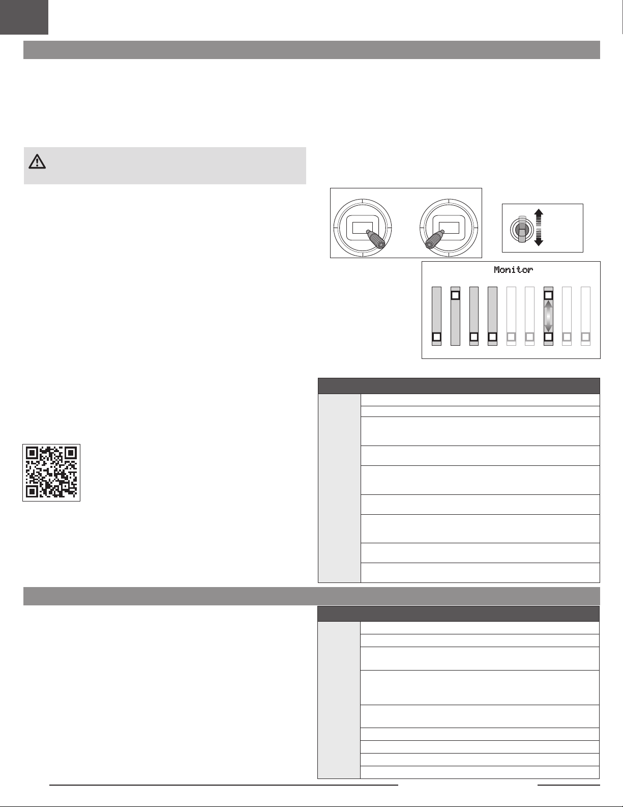
FR
Désignation du commutateur SAFE® Select
Entrées manches
Une fois SAFE Select activé, vous pouvez choisir de voler continuellement en mode
SAFE ou d’attribuer la fonction à un commutateur. N’importe quel commutateur sur
n’importe quel canal entre 5 et 9 peut être utilisé sur votre émetteur.
Si l’appareil est affecté avec le mode SAFESelect désactivé, l’appareil est
uniquement en mode AS3X.
ATTENTION: maintenez toutes les parties du corps loin de l’hélice et
gardez l’appareil solidement immobilisé en cas d’activation accidentelle
des gaz.
IMPORTANT: pour pouvoir attribuer la fonction à un commutateur, il est d’abord
nécessaire de vérier:
• L’appareil a été affecté avec le mode SAFE Select activé.
• Votre choix du commutateur SAFE Select est attribué à un canal entre 5 et 9
(Train, Aux. 1-4), et la course est paramétrée sur 100% dans chaque direction.
• L’aileron, la gouverne de profondeur, la gouverne de direction et la direction des
gaz sont paramétrés sur normal,
pas inversion.
• L’aileron, la gouverne de profondeur, la gouverne de direction et les gaz
sont paramétrés sur une course à 100%. Si des doubles débattements
sont utilisés, les commutateurs doivent être en position 100%.
Consultez le manuel de votre émetteur pour obtenir plus d’informations sur
l’attribution d’un commutateur à un canal.
CONSEIL: si vous souhaitez un commutateur SAFE Select pour votre appareil à
6fonctions, et si vous utilisez un émetteur à 6canaux, le canal du commutateur
SAFE Select devra être partagé avec soit le canal 5 soit le canal 6 de l’émetteur.
Attribution d’un commutateur
1. Mettez l’émetteur en marche.
2. Mettez l’avion en marche.
3. Maintenez les deux manches de l’émetteur vers les coins inférieurs à l’intérieur
et faites basculer rapidement 5fois le commutateur souhaité (1 basculement
= entièrement vers le haut et vers le bas).
4. Les gouvernes de l’appareil se déplaceront, indiquant que le commutateur a
été sélectionné.
Répétez l’opération pour attribuer un commutateur différent ou pour désactiver le
commutateur actuel.
SAFE Select Switch Assignment Stick Positions
Émetteurs de mode1 et 2
Attribution d’un commutateur
100%
X 5
100%
CONSEIL: utilisez le
moniteur de canal pour
vérier le mouvement de
canal.
Cet exemple de moniteur
de canal montre les
positions des manches
pour l’attribution d’un
commutateur, la sélection
du commutateur sur Aux2 et
une course +/- 100% sur le
commutateur.
-100
THR
100
AIL
-100
ELE
Monitor
-100
-100
RUD
GER
-100
AX1
+/-100
AX2
-100
AX3
-100
AX4
Programmation en aval
Affectez le canal SAFE Select par le biais de la programmation en aval sur votre
émetteur Spektrum compatible.
Pour plus d’informations sur la conguration de SAFE Select
et l’utilisation de la programmation en aval, cliquez sur le lien
suivant pour obtenir une vidéo détaillée:
https://www.youtube.com/watch?v=o-46P066cik
Télémétrie ESC intégrée
BNF: cet avion est doté de la télémétrie entre le variateur ESC et le récepteur, qui
permet de fournir des informations, notamment: régime, tension, courant moteur,
paramètres de gaz (%) et température du FET (régulateur de vitesse).
PNP: le variateur ESC de cet avion est capable de fournir des informations via la
télémétrie par le biais de la connexion des gaz quand il est associé à un récepteur
avec télémétrie Spektrum compatible Smart. Il fonctionne avec un signal de servo
PWM normal pour les systèmes de commande radio courants.
Pour plus d’informations sur les émetteurs compatibles, les mises à jour du micrologiciel et l’utilisation de la technologie télémétrique sur votre émetteur, consultez
www.SpektrumRC.com.
54
Programmation en aval - Conguration de SAFE Select
1. Commencez avec l’émetteur affecté au récepteur.
2. Allumez l’émetteur.
3. Affectez un commutateur pour SAFE Select qui n’est pas encore
utilisé pour une autre fonction. Utilisez n’importe quel canal ouvert
entre 5 et 9 (Train, Aux. 1-4).
4. Congurez le commutateur H (coupure des gaz) an de prévenir le
Série DX,
série NX,
série iX
fonctionnement accidentel du moteur.
5. Mettez l’avion en marche. Une barre de signal s’afche sur l’écran
principal de votre émetteur lorsque les informations de télémétrie
sont reçues.
6. Accédez à la FUNCTION LIST (LISTE DES FONCTIONS)
(conguration du modèle)
7. Sélectionnez Forward Programming (Programmation en aval);
Sélectionnez Gyro Settings (Réglages des gyroscopes),
Sélectionnez SAFE Select pour entrer dans le menu.
8. Congurez SAFE Select Ch (Canal SAFESelect): Sur le canal que
vous avez choisi pour SAFE Select.
9. Congurez AS3X et SAFESelect sur On (allumé) ou Off (éteint)
comme bon vous semble pour chaque position de commutateur.
Conguration de la télémétrie
1. Commencez avec l’émetteur affecté au récepteur.
2. Allumez l’émetteur.
3. Congurez le commutateur H (Arrêt du moteur) an de prévenir le
fonctionnement accidentel du moteur.
4. Mettez l’avion en marche. Une barre de signal s’afche sur l’écran
Série DX,
série NX,
série iX
principal de votre émetteur lorsque les informations de télémétrie
sont reçues.
5. Accédez à la FUNCTION LIST (LISTE DES FONCTIONS)
(conguration du modèle)
6. Sélectionnez TÉLÉMÉTRIE; Variateur ESC Smart
7. Dénissez le nombre total de cellules: 3
8. Dénissez l’alarme LVC: 3,4V Dénissez l’alarme; Voix/Vibration
9. Dénissez le nombre de pôles; 14pôles
Slow Ultra Stick 1.2m
Page 55

Test de contrôle de la direction
Allumez l’émetteur et raccordez la batterie. Utilisez l’émetteur pour commander
l’aileron, la gouverne de profondeur et la gouverne de direction. Regardez
l’appareil de l’arrière pour vérier les directions de commande.
Ce modèle possède un mixage aileron/gouvernail intégré, lorsque les ailerons sont
en position de débattement, le gouvernail se déplace.
Gouverne de profondeur
1. Tirez la manette de gouverne de profondeur en arrière. Les gouvernes de
profondeur s’élèvent, ce qui fait cabrer l’appareil.
2. Poussez la manette de gouverne de profondeur vers l’avant. Les gouvernes de
profondeur s’abaissent, ce qui fait descendre l’appareil.
Ailerons
1. Déplacez la manette d’aileron vers la droite. L’aileron droit s’élève et l’aileron
gauche s’abaisse, ce qui fera se pencher l’appareil vers la droite.
2. Déplacez la manette d’aileron vers la gauche. L’aileron gauche s’élève et
l’aileron droit s’abaisse, ce qui fera se pencher l’appareil vers la gauche.
Gouverne de direction
1. Déplacez le manche de la gouverne de direction vers la droite. La gouverne se
déplace vers la droite, ce qui fera effectuer à l’appareil un lacet vers la droite.
2. Déplacez le manche de la gouverne de direction vers la gauche. La gouverne
se déplace vers la gauche, ce qui fera effectuer à l’appareil un lacet vers la
gauche.
FR
Cammande de l’émetteur Résponse des gouvernes
Profondeur
AileronDérive
55
Page 56

FR
Essai de la réponse de l’AS3X®
Ce test permet de s’assurer du bon fonctionnement du système AS3X. Assemblez
le modèle et affectez votre émetteur au récepteur avant d’effectuer ce test.
1. Pour activer l’AS3X, placez le manche des gaz juste au dessus des 25% de sa
course, puis replacez-le en position basse.
ATTENTION: Tenez vos cheveux, vos vêtements amples, vos mains et
autres parties du corps à l’écart de l’hélice, elle pourrait les attraper.
2. Déplacez l’avion comme sur les illustrations et contrôlez que les gouvernes
se déplacent dans la direction indiquée sur l’illustration. Si les gouvernes
ne répondent pas comme sur les illustrations, ne faites pas voler le
modèle. Référez-vous au manuel du récepteur pour des informations
complémentaires.
Une fois le système AS3X activé, les gouvernes peuvent s’agiter rapidement. Il s’agit
d’une réaction normale. L’AS3X restera actif jusqu’à la déconnexion de la batterie.
En raison des différents effets de couple, de portance et de traînée, certains avions
nécessitent des modications de trim (compensateur) avec différents vitesses et
réglages de gaz. Des mixages sont préchargés dans le récepteur pour compenser
ces changements. Les mixages s’activent la première fois que les gaz dépassent
les 25%. Les gouvernes peuvent être légèrement décalées avec différents
réglages de gaz après la première augmentation des gaz. La compensation de
l’avion en vol doit s’effectuer avec des gaz à 80-100% pour obtenir des résultats
optimaux.
Mouvement de l’avion Réaction de l’AS3X
Profondeur
AileronDérive
56
Slow Ultra Stick 1.2m
Page 57

Control Surface Centering and Adjusting a Clevis
IMPORTANT: Perform the Control Direction Test before performing control surface
centering.
While SAFE is inactive, mechanically center the control surfaces.
IMPORTANT: Correct operation of the SAFE system requires sub-trim and trim at 0.
After binding a transmitter to the receiver, set the trims and sub-trims to 0, ensure
the servo arms are in the correct positions, then adjust the linkages to center the
control surfaces.
Retirez la manille
1. Faites glisser le tube de retenue hors de la manille.
2. Écartez la manille avec précaution et retirez la broche de la manille du guignol
de commande.
Ajuster la manille
3. Tournez la manille pour ajuster la longueur de la barre de liaison.
Réinstaller la manille
4. Écartez la manille avec précaution, puis insérez la broche de la manille dans le
trou spécié sur le guignol de commande.
5. Déplacez le tube de retenue pour xer la manille sur le guignol de commande.
FR
1.
2.
3.
4.
5.
6.
Réglages aux guignols et aux palonniers de servos
Le tableau de droite indique les réglages d’usine des guignols de commande et
des bras de servo. Pilotez votre appareil avec les réglages d’usine avant d’apporter
toute modication.
Augmentation du coude de
commande
Réduction du coude de
commande
Doubles débattements
Programmez votre émetteur pour congurer les débattements et les coudes de
commande aux valeurs indiquées. Ces valeurs ont été testées et sont un bon point
de départ pour réussir à voler.
Gouverne de
profondeur
Gouverne de
direction
Ailerons
Ailerons
Gouverne de
profondeur
Gouverne de
direction
Guignols de commande Bras de servo
Grand débattement Petit débattement
p = 12mm
q = 12mm
p = 15mm
q = 15mm
= 25mm
= 25mm
p = 8mm
q = 8mm
p = 11mm
q = 11mm
= 15mm
= 15mm
57
Page 58

FR
(CG) Centre de Gravité
L’emplacement du CG est mesuré à partir du bord d’attaque de l’aile.
L’emplacement du CG a été déterminé avec la batterie Li-Po 3S 1300mAh
recommandée (SPMX133S30) installée sur le bord avant du support de batterie.
Ajustez la batterie vers l’avant ou l’arrière si nécessaire pour atteindre le bon
emplacement du CG.
ATTENTION: Installez la batterie, mais n’armez pas le variateur ESC en vériant
le CG. Vous risqueriez de vous blesser.
Conseils de vol en mode SAFE Select
115mm +/-5
en arrière du bord
d’attaque.
Lors d’un vol au mode SAFE Select, l’appareil retournera en vol à niveau à
tout moment lorsque les commandes d’aileron et de gouverne de profondeur
sont en position neutre. L’utilisation des commandes d’aileron ou de gouverne
de profondeur fera s’incliner, grimper ou plonger l’appareil. La quantité de
déplacement du manche déterminera l’attitude de vol de l’appareil. En maintenant
le contrôle complet, l’appareil sera poussé vers les limites prédéterminées
d’inclinaison et de roulis, mais ne dépassera pas ces angles.
Lors d’un vol au mode SAFE Select, il est normal de maintenir le manche de
commande en déviation avec une saisie modérée d’aileron en volant à travers
un virage. Pour voler correctement avec SAFE Select, évitez d’effectuer des
changements de contrôles fréquents et n’essayez pas de corriger les déviations
mineures. Le maintien de saisies de commande délibérées commandera à
l’appareil de voler à un angle spécique et le modèle effectuera toutes les
corrections pour maintenir cette attitude de vol.
Lorsque vous volez avez SAFE Select, les gaz entraînent la montée ou la descente
de l’appareil. La position plein régime fera cabrer et monter légèrement l’appareil.
La position médiane des gaz maintiendra l’appareil en palier. La position faible
ouverture des gaz entraînera une légère descente en piqué de l’appareil.
Remettez les commandes de gouverne de profondeur et d’aileron en position
neutre avant de basculer du mode SAFE Select au mode AS3X. Si vous ne
Réglage des trims en vol
Lors de votre premier vol, procédez aux réglages de compensation de l’appareil
pour le faire voler en palier avec les gaz aux 80-100%. Effectuez de légers
réglages de trim (compensation) à l’aide des interrupteurs de compensation de
votre émetteur an d’obtenir un vol droit et à niveau.
neutralisez pas les commandes en basculant au mode AS3X, les saisies de
commandes utilisées pour le mode SAFE Select seront excessives pour le mode
AS3X et l’appareil réagira immédiatement.
Différences entre les modes SAFE Select et AS3X
Cette section est généralement précise mais ne tient pas compte de la vitesse de
vol, de l’état du chargeur de batterie et d’autres facteurs limitatifs.
SAFE Sélectionner AS3X
Le manche de
commande est
neutralisé
Avoir une petite
quantité de
contrôle
Garder le contrôle total
Entrée de contrôle
Manette de Gaz
3 Seconds
L’avion s’auto-nivellera
L’avion s’inclinera ou
tanguera à un angle modéré
et maintiendra l’assiette
L’avion s’inclinera ou
tanguera jusqu’aux
limites prédéterminées et
maintiendra l’assiette
Plein gaz : montée
Neutre : Vol en palier
Gaz bas : Descendre
L’avion continuera à
voler à son assiette
actuelle
L’avion continuera à
tanguer ou à rouler
lentement
L’avion continuera à
rouler ou à tanguer
rapidement
L’accélérateur
n’affectera pas la
réponse en vol.
Une fois les réglages de compensation effectués, ne touchez pas les manches de
commande pendant trois secondes. Cela permet au récepteur AS3X de mémoriser
les bons réglages et d’optimiser ainsi ses performances.
Le non-respect de cette recommandation pourrait nuire à la performance en vol.
58
Slow Ultra Stick 1.2m
Page 59

Conguration de l’aileron à deux servos en option
1. Retirez l’aile de l’appareil.
2. Retirez la vis du bras de servo et le bras du servo installé.
3. Retirez le bras de servo du coude en Z de chaque barre de liaison.
4. Retirez les 2vis qui xent le servo à l’aile.
5. Repositionnez le servo à gauche de l’encoche du servo, en l’alignant avec les
trous de vis de gauche.
6. Acheminez le l et le connecteur du servo à travers l’encoche du servo et xez
le servo avec les 2vis.
7. Installez un second servo d’aileron (SPMSA345SL, non inclus) à droite dans
l’encoche du servo.
8. Acheminez la che et le connecteur de servo dans le canal de droite partant de
l’encoche du servo et alignez les vis avec les trous de vis et xez en place.
9. Connectez le servo de droite au canal 2 et le servo de gauche au canal 6 du
récepteur.
10. À l’écran System Setup (Conguration système) de votre émetteur, mettez le
Aircraft Type (Type d’appareil) sur Dual Aileron (Aileron double).
11. Connectez une batterie à l’appareil et allumez l’appareil pour centrer les
servos.
12. Connectez le coude en Z des tringleries de commande à l’orice le plus à
l’extérieur du nouveau guignol de servo (EFL0370, requis et non inclus).
Répétez l’opération pour l’autre guignol de servo.
13. Installez le guignol de servo sur le servo aussi près que possible des 90degrés
et xez avec une vis.
14. Installez l’extrémité à manille de la nouvelle tringlerie sur l’orice le plus à
l’extérieur du guignol de commande de l’aileron.
15. Assurez-vous que les surfaces de commande de l’aileron sont centrées,
ajustez mécaniquement la barre de liaison si nécessaire pour centrer l’aileron.
16. Installez l’aile sur le fuselage.
FR
Bras du servo de l’aileron
Guignol de commande de l’aileron
Tube de retenue
Barre de liaison Manille
Conguration informatisée de l’émetteur
Démarrez toutes les programmations de l’émetteur avec un modèle vierge ACRO
(effectuez une réinitialisation du modèle), puis nommez le modèle.
Congurez les Dual Rates
(doubles débattements)
sur
Congurez la Servo
Travel (course de servo)
sur
Congurez le Throttle Cut
(arrêt du moteur) sur
‡
DX6e
DX6 ‡ (Gén. 2)
DX7‡ (Gén. 2)
‡
NX6
1. Accédez à SYSTEM SETUP (CONFIGURATION DU SYSTÈME)
(Model Utilities (équipements du modèle))†
2. Congurez le MODEL TYPE (TYPE DE MODÈLE): AIRPLANE
(AVION)
DX8e
DX8 (Gén. 2)
DX9
DX10t
DX18
DX20
iX12
iX20
†
†
3. Configurez l’AIRCRAFT TYPE (TYPE D’APPAREIL): Model
Setup (configuration du modèle), Aircraft Type (type
d’appareil)†:
WING: Dual Aileron
NX6
NX8
NX10
Commutateur à
2positions
HIGH (ÉLEVÉ) 100%
LOW (FAIBLE) 70% LOW (FAIBLE) 50%
100%
-100%
Commutateur à
3positions
HIGH (ÉLEVÉ) 100%
MID (MOYEN) 70%
59
Page 60

FR
Maintenance après vol
1. Débranchez la batterie de vol du variateur ESC (nécessaire par mesure de
sécurité et pour préserver la durée de vie de la batterie).
2. Éteignez l’émetteur.
3. Retirez la batterie de vol de l’appareil.
4. Réparez ou remplacez toutes les pièces endommagées.
Opéperation de maintenance sur le moteur
ATTENTION: déconnectez toujours la batterie de vol avant d’effectuer une
opération de maintenance sur le moteur.
Démontage
1. Retirez le cône (A), la vis (B), la rondelle de retenue du cône (C), l’écrou de
l’hélice (D) et l’hélice (E).
2. Retirez les 4vis (F) de l’arbre de l’hélice (G).
3. Retirez l’arbre de l’hélice de l’arbre du moteur.
4. Retirez les 2vis (H) du support moteur (I) et du fuselage.
5. Débranchez les câbles du moteur des câbles du variateur ESC.
Assemblage
Montez dans l’ordre inverse.
• Alignez et connectez les ls du moteur aux ls du variateur ESC en respectant
les couleurs.
• Installez l’hélice avec les numéros de taille (11x5,5) orientés vers l’avant.
• Serrez l’écrou de l’hélice à l’aide d’une clé de 10mm.
• Poussez le cône en caoutchouc sur la rondelle de retenue du cône en plastique.
5. Stockez la batterie de vol en dehors de l’appareil et surveillez la charge de la
batterie.
6. Notez les conditions de vol et les résultats de vol pour prévoir les futurs vols.
E
H
I
D
B
G
F
C
Le câblage n’est pas
A
représenté
Entretien des servos
Gouverne Servo de rechange Description
Aileron
Gouverne de profon-
deur
Gouverne de direction
SPMSA345SL Servo 9g Sub-Micro A345SL
Guide de dépannage AS3X
Problème Cause Possible Solution
Hélice ou cône endommagé Remplacez l’hélice ou le cône
Équilibrez l’hélice. Pour plus d'informations, regardez la vidéo de John Redman sur
l’équilibrage des hélices sur www.horizonhobby.com
Avec le manche des gaz à sa position la plus basse, déconnectez la batterie, puis reconnectezla et maintenez le modèle immobile 5 secondes
NE PAS faire voler l’aéronef. Contacter le service après-vente pour obtenir une solution.
Oscillations
Performances de vol aléatoires
Mauvaise réponse de l’appareil
aux essais de commande du
système AS3X
Hélice déséquilibrée
Vibration du moteur Remplacez les pièces endommagées et contrôlez le serrage et l'alignement des pièces
Récepteur mal xé Réalignez et rexez le récepteur
Commandes desserrées Resserrez et vériez l'état des pièces (servos, palonniers, tringleries, guignols et gouvernes)
Pièces usées Remplacez les pièces usées (hélice, cône ou servo)
Fonctionnement erratique du servo Remplacez le servo
Le trim n’est pas au neutre Si vous ajustez les trims plus de 8 clics, ajustez la chape pour annuler le trim
Le sub-trim n’est pas au neutre L’utilisation des sub-trims n’est pas permise. Réglez directement les tringleries
L’avion n’est pas resté immobile
durant 5 secondes
Paramétrage incorrect des directions
des commandes du récepteur,
pouvant causer un crash
60
Slow Ultra Stick 1.2m
Page 61

Guide de dépannage
Problème Cause Possible Solution
Le modèle ne répond
pas aux gaz mais bien
aux autres commandes
L’hélice fait trop de
bruit ou vibre trop
Durée de vol réduite ou
manque de puissance
du modèle
Le modèle n’accepte
pas l’affectation (au
cours de la procédure)
à l’émetteur
Le modèle ne veut pas
établir la liaison avec
l’émetteur
(après affectation)
Les gouvernes ne
bougent pas
Le manche des gaz n’est pas au ralenti (idle) et/ou le trim
des gaz est réglé à une valeur trop élevée
La course du servo des gaz est inférieure à 100% Assurez-vous que la course du servo des gaz est de 100%
La voie des gaz est inversée Inversez la voie des gaz sur l’émetteur
Moteur déconnecté du contrôleur Assurez-vous que le moteur est bien connecté au contrôleur
Hélice, cône, adaptateur ou moteur endommagé Remplacez les pièces endommagées
Déséquilibre de l’hélice Équilibrez ou remplacez l’hélice
Écrou de l’hélice desserré Resserrez l’écrou
La charge de la batterie de vol est faible Rechargez la batterie de vol complètement
Hélice montée à l’envers Montez l’hélice correctement avec les chiffres orientés vers l'avant
Batterie de vol endommagée Remplacez la batterie de vol et suivez les instructions la concernant
Les conditions de vol sont peut-être trop froides Assurez-vous que la batterie est à température avant de l’utiliser
Capacité de la batterie trop faible pour les conditions de vol Remplacez la batterie ou utilisez une batterie à plus grande capacité
Émetteur trop près du modèle durant la procédure
d’affectation
Le modèle ou l’émetteur se trouve trop près d’un objet
métallique, d'un réseau sans l ou d'un autre émetteur
La prise affectation n’est pas bien installée dans le port
d’affectation
La charge de la batterie de vol/de l’émetteur est trop faible Remplacez/rechargez les batteries
Bouton ou interrupteur d’affectation n’a pas été pressé
assez longtemps pendant l’affectation
Émetteur trop près de l’aéronef lors du processus
d’établissement de liaison
Le modèle ou l’émetteur se trouve trop près d’un objet
métallique, d'un réseau sans l ou d'un autre émetteur
La prise affectation est restée dans le port affectation Ré-affectez l’émetteur au modèle et retirez la prise affectation avant de redémarrer
Modèle affecté à une mémoire de modèle différente
(émetteur ModelMatch uniquement)
La charge de la batterie de vol/de l’émetteur est trop faible Remplacez/rechargez les batteries
L’émetteur a peut-être été affecté en utilisant un protocole
DSM différent
Gouverne, guignol, tringlerie ou servo endommagé Remplacez ou réparez les pièces endommagées et réglez les commandes
Câblage endommagé ou connexions lâches Contrôlez les câbles et les connexions, connectez ou remplacez si besoin
L’émetteur n’est pas affecté correctement ou il y a eu
mauvaise sélection du modèle
La charge de la batterie de vol est faible Rechargez la batterie de vol complètement
Le circuit BEC (Battery Elimination Circuit) du contrôleur
est endommagé
Réinitialisez les commandes avec le manche des gaz et le trim des gaz sur la
position plus faible possible
Déplacez l’émetteur allumé à quelques pas du modèle, déconnectez la batterie de
vol du modèle et reconnectez-la
Placez le modèle et l'émetteur à un autre endroit et retentez l'affectation
Installez la prise affectation dans le port d’affectation et affectez le modèle à l’émetteur
Mettez l’émetteur hors tension et répétez la procédure d’affectation. Maintenez le
bouton ou l'interrupteur d’affectation jusqu’à ce que le récepteur soit affecté
Déplacez l’émetteur allumé à quelques pas du modèle, déconnectez la batterie de
vol du modèle et reconnectez-la
Déplacez le modèle ou l’émetteur à bonne distance et retentez la liaison
Sélectionnez la bonne mémoire de modèle sur l’émetteur
Affectez le modèle à l’émetteur
Effectuez une nouvelle affectation ou sélectionnez le bon modèle dans l’émetteur
Remplacez le contrôleur
FR
61
Page 62

FR
Pièces de rechange Pièces facultatives
Référence Description
EFL0351 Aile droite: Slow Ultra Stick
EFL0352 Aile gauche: Slow Ultra Stick
EFL0353 Tige d’aile: Slow Ultra Stick
EFL0354 Tube d’aile: Slow Ultra Stick
EFL0355 Ensemble de vis à oreilles: Slow Ultra Stick
EFL0356 Support d’aile avant: Slow Ultra Stick
EFL0357 Support d’aile arrière: Slow Ultra Stick
EFL0358 Support de montage: Slow Ultra Stick
EFL0359 Support du moteur: Slow Ultra Stick
EFL0360 Cône en caoutchouc: Slow Ultra Stick
EFL0361 Adaptateur d’hélice : Slow Ultra Stick
EFL0362 Ensemble train d’atterrissage: Slow Ultra Stick
EFL0363 Ensemble guignol de commande: Slow Ultra Stick
EFL0364 Ensemble de liaison de commande: Slow Ultra Stick
EFL0365 Ensemble de dispositif de retenue du l: Slow Ultra Stick
EFL0366 Fuselage: Slow Ultra Stick
EFL0367 Tige de fuselage: Slow Ultra Stick
EFL0368 Stabilisateur vertical: Slow Ultra Stick
EFL0369 Stabilisateur horizontal: Slow Ultra Stick
EFL0370 Ensemble de bras de servo: Slow Ultra Stick
EFL0371 Feuillet d’autocollants: Slow Ultra Stick
EFL0372 Ensemble d’éléments de xation: Slow Ultra Stick
EFLP1155 Hélice: 11X5,5
SPMSA345SL Servo Sub-Micro 9g A345SL; l de 60mm
SPMXAE30D Variateur ESC sans balais 30A Smart Avian
SPMXAM2800 Moteur sans balais: 3513-1100kV
SPMAR630 Récepteur AR630 DSMX 6 canaux AS3X et SAFE
Éléments recommandés
Référence Description
SPMR6655 Émetteur DX6e 6canaux uniquement
SPMX133S30 Batterie 1300mAh 3S 11,1V Smart G2 30C;
SPMXC2050 Chargeur Smart CA S155 G2 1x55W
Référence Description
SPMR8105 Émetteur uniquement 8canaux NX8e
SPMR6775 Émetteur uniquement 6canaux NX6
SPMR8200 Émetteur uniquement 8canaux NX8
SPMXC2080 Chargeur c.a. Smart S1100 G2, 1x100W
SPMX22003S30 2200mAh 3S 11,1V Smart 30C; IC3
SPMX223S30 Batterie 2200mAh 3S 11,1V Smart G2 30C;
APC11055E Hélice électrique, 11x5.5E
SPMSA345SL Servonumérique Sub-Micro 9g A345; l de 60mm
EFL0370 Ensemble de bras de servo: Slow Ultra Stick
Matériel
Quantité Emplacement Description
4 Vis mécanique M3x6mm
1 Vis mécanique M2x6mm
1 Vis à oreilles M3x22mm
Vis autotaraudeuse 2,3x
3
4,5mm
4 Vis autotaraudeuse 2x8mm
Vis mécanique à oreilles
2
M3x22mm
1 Vis mécanique M3x6mm
1 Écrou de vis d’hélice M6 Pour xer l’hélice à l’arbre d’hélice
4 Vis mécanique M2x7mm
1 Vis mécanique M2x14mm
1 Vis mécanique M2x14mm
1 Vis mécanique M2x14mm
1 Vis mécanique M2x14mm
1 Vis mécanique M2x6mm
6 Vis autotaraudeuse 2x8mm Pour xer les servos au fuselage
4 Vis mécanique M2x14mm
1 12.8mm x 500mm Tube d’aile
Diamètre 85mm, Largeur
2
17mm, Moyeu 3mm
Diamètre 21mm, Largeur 7mm,
1
Moyeu 1,3mm
Pour xer le moteur sur la xation
du moteur
Pour xer le support du variateur
ESC au fuselage
Pour xer le stabilisateur horizontal
au fuselage
Pour xer le bras de servo sur le
servo
Pour xer le guignol de commande
sur la gouverne
Pour xer l’aile au fuselage
Pour xer la rondelle de retenue
du cône
Pour xer l’adaptateur d’hélice au
moteur
Pour xer le support du moteur au
fuselage
Pour xer le support de batterie au
fuselage
Pour xer le support avant de l’aile
au fuselage
Pour xer le support arrière de
l’aile au fuselage
Pour xer le support du récepteur
au fuselage
Pour xer les deux moitiés du
fuselage ensemble
Roue principale
Roue de queue
62
Slow Ultra Stick 1.2m
Page 63

Garantie et réparations
Durée de la garantie
Garantie exclusive - Horizon Hobby, LLC (Horizon) garantit que le Produit acheté (le
« Produit ») sera exempt de défauts matériels et de fabrication à sa date d’achat
par l’Acheteur. La durée de garantie correspond aux dispositions légales du pays
dans lequel le produit aété acquis. La durée de garantie est de 6 mois et la durée
d’obligation de garantie de 18 mois à l’expiration de la période de garantie.
Limitations de la garantie
(a) La garantie est donnée à l’acheteur initial (« Acheteur ») et n’est pas transférable.
Le recours de l’acheteur consiste en la réparation ou en l’échange dans le cadre
de cette garantie. La garantie s’applique uniquement aux produits achetés chez
un revendeur Horizon agréé. Les ventes faites à des tiers ne sont pas couvertes
par cette garantie. Les revendications en garantie seront acceptées sur fourniture
d’une preuve d’achat valide uniquement. Horizon se réserve le droit de modifier
les dispositions de la présente garantie sans avis préalable et révoque alors les
dispositions de garantie existantes.
(b) Horizon n’endosse aucune garantie quant à la vendabilité du produit ou aux
capacités et à la forme physique de l’utilisateur pour une utilisation donnée du
produit. Il est de la seule responsabilité de l’acheteur de vérifier si le produit
correspond à ses capacités et à l’utilisation prévue.
(c) Recours de l’acheteur – Il est de la seule discrétion d’Horizon de déterminer si
un produit présentant un cas de garantie sera réparé ou échangé. Ce sont là les
recours exclusifs de l’acheteur lorsqu’un défaut est constaté.
Horizon se réserve la possibilité de vérifier tous les éléments utilisés et susceptibles
d’être intégrés dans le cas de garantie. La décision de réparer ou de remplacer le
produit est du seul ressort d’Horizon. La garantie exclut les défauts esthétiques ou
les défauts provoqués par des cas de force majeure, une manipulation incorrecte
du produit, une utilisation incorrecte ou commerciale de ce dernier ou encore des
modifications de quelque nature qu’elles soient.
La garantie ne couvre pas les dégâts résultant d’un montage ou d’une manipulation
erronés, d’accidents ou encore du fonctionnement ainsi que des tentatives d’entretien
ou de réparation non effectuées par Horizon. Les retours effectués par le fait de
l’acheteur directement à Horizon ou à l’une de ses représentations nationales
requièrent une confirmation écrite.
Limitation des dommages
Horizon ne saurait être tenu pour responsable de dommages conséquents directs ou
indirects, de pertes de revenus ou de pertes commerciales, liés de quelque manière
que ce soit au produit et ce, indépendamment du fait qu’un recours puisse être
formulé en relation avec un contrat, la garantie ou l’obligation de garantie. Par ailleurs,
Horizon n’acceptera pas de recours issus d’un cas de garantie lorsque ces recours
dépassent la valeur unitaire du produit. Horizon n’exerce aucune influence sur le
montage, l’utilisation ou la maintenance du produit ou sur d’éventuelles combinaisons
de produits choisies par l’acheteur. Horizon ne prend en compte aucune garantie et
n‘accepte aucun recours pour les blessures ou les dommages pouvant en résulter.
Horizon Hobby ne saurait être tenu responsable d’une utilisation ne respectant pas les
lois, les règles ou règlementations en vigueur.
En utilisant et en montant le produit, l’acheteur accepte sans restriction ni réserve toutes
les dispositions relatives à la garantie figurant dans le présent document. Si vous n’êtes
pas prêt, en tant qu’acheteur, à accepter ces dispositions en relation avec l’utilisation du
produit, nous vous demandons de restituer au vendeur le produit complet, non utilisé et
dans son emballage d’origine.
FR
Indications relatives à la sécurité
Ceci est un produit de loisirs perfectionné et non un jouet. Il doit être utilisé avec
précaution et bon sens et nécessite quelques aptitudes mécaniques ainsi que
mentales. L’incapacité à utiliser le produit de manière sure et raisonnable peut
provoquer des blessures et des dégâts matériels conséquents. Ce produit n’est pas
destiné à être utilisé par des enfants sans la surveillance par un tuteur. La notice
d’utilisation contient des indications relatives à la sécurité ainsi que des indications
concernant la maintenance et le fonctionnement du produit. Il est absolument
indispensable de lire et de comprendre ces indications avant la première mise en
service. C’est uniquement ainsi qu’il sera possible d’éviter une manipulation erronée
et des accidents entraînant des blessures et des dégâts. Horizon Hobby ne saurait
être tenu responsable d’une utilisation ne respectant pas les lois, les règles ou
règlementations en vigueur.
Questions, assistance et réparations
Votre revendeur spécialisé local et le point de vente ne peuvent effectuer une
estimation d’éligibilité à l’application de la garantie sans avoir consulté Horizon. Cela
vaut également pour les réparations sous garantie. Vous voudrez bien, dans un tel
cas, contacter le revendeur qui conviendra avec Horizon d’une décision appropriée,
destinée à vous aider le plus rapidement possible.
Maintenance et réparation
Si votre produit doit faire l’objet d’une maintenance ou d’une réparation, adressezvous soit à votre revendeur spécialisé, soit directement à Horizon. Emballez le produit
soigneusement. Veuillez noter que le carton d’emballage d’origine ne suffit pas,
en règle générale, à protéger le produit des dégâts pouvant survenir pendant le
transport. Faites appel à un service de messagerie proposant une fonction de suivi
et une assurance, puisque Horizon ne prend aucune responsabilité pour l’expédition
du produit jusqu’à sa réception acceptée. Veuillez joindre une preuve d’achat, une
description détaillée des défauts ainsi qu’une liste de tous les éléments distincts
envoyés. Nous avons de plus besoin d’une adresse complète, d’un numéro de
téléphone (pour demander des renseignements) et d’une adresse de courriel.
Garantie et réparations
Les demandes en garantie seront uniquement traitées en présence d’une preuve
d’achat originale émanant d’un revendeur spécialisé agréé, sur laquelle figurent le
nom de l’acheteur ainsi que la date d’achat. Si le cas de garantie est confirmé, le
produit sera réparé. Cette décision relève uniquement d’Horizon Hobby.
Réparations payantes
En cas de réparation payante, nous établissons un devis que nous transmettons à
votre revendeur. La réparation sera seulement effectuée après que nous ayons reçu la
confirmation du revendeur. Le prix de la réparation devra être acquitté au revendeur.
Pour les réparations payantes, nous facturons au minimum 30 minutes de travail en
atelier ainsi que les frais de réexpédition. En l’absence d’un accord pour la réparation
dans un délai de 90 jours, nous nous réservons la possibilité de détruire le produit ou
de l’utiliser autrement.
ATTENTION: Nous n’effectuons de réparations payantes que pour les composants
électroniques et les moteurs. Les réparations touchant à la mécanique, en particulier
celles des hélicoptères et des voitures radiocommandées, sont extrêmement
coûteuses et doivent par conséquent être effectuées par l’acheteur lui-même.
10/15
63
Page 64

FR
Informations de contact pour garantie et réparation
Pays d’achat Horizon Hobby Numéro de téléphone/E-mail Adresse
Union européenne
Horizon Technischer Service service@horizonhobby.eu
Sales: Horizon Hobby GmbH +49 (0) 4121 2655 100
Hanskampring 9
D 22885 Barsbüttel, Germany
Informations IC
IC: 6157A-SPMAR630
CAN ICES-3 (B)/NMB-3(B)
Ce dispositif contient un/des émetteur(s)/récepteur(s) non soumis à licence
conforme(s) aux CNR d’Innovation, Sciences et Développement économique
Canada. Son utilisation est soumise aux deux conditions suivantes:
1. Cet appareil ne doit pas causer d’interférences.
2. Cet appareil doit accepter toutes les interférences, y compris celles pouvant
entraîner un dysfonctionnement.
Informations de conformité pour l’Union européenne
Déclaration de conformité aux normes de l’UE
EFL Slow Ultra Stick Manual 1.2M BNF Basic (EFL0350); Par la
présente, Horizon Hobby, LLC déclare que cet appareil est conforme
aux directives suivantes : Directive CEM 2014/30/UE, Directive RoHS 2 2011/65/
UE, Directive RoHS 3 - Modiant 2011/65/UE Annexe II 2015/863..
Le texte complet de la déclaration de conformité aux normes de l’UE est disponible
à l’adresse Internet suivante : https://www.horizonhobby.com/ content/supportrender-compliance.
Plage de fréquences sans l et puissance de sortie sans l :
2402-2478MHz
4.65dBm
NOTE DEEE :
L’étiquette de cet appareil respecte la directive européenne 2012/19/UE
en matière de déchets des équipements électriques et électroniques
(DEEE). Cette étiquette indique que ce produit ne doit pas être jeté avec
les déchets ménagers, mais déposé dans une installation appropriée
an de permettre sa récupération et son recyclage.
Fabricant ofciel pour l’UE :
Horizon Hobby, LLC
2904 Research Road
Champaign, IL 61822 USA
Importateur ofciel pour l’UE :
Horizon Hobby, GmbH
Hanskampring 9
22885 Barsbüttel Germany
Australia/New Zealand:
64
Slow Ultra Stick 1.2m
Page 65

IT
AVVISO
Tutte le istruzioni, le garanzie e gli altri documenti pertinenti sono soggetti a cambiamenti a totale discrezione di Horizon Hobby, LLC. Per una documentazione
aggiornata sul prodotto, visitare il sito horizonhobby.com o towerhobbies.com e fare clic sulla sezione Support del prodotto.
CONVENZIONI TERMINOLOGICHE
Nella documentazione relativa al prodotto vengono utilizzati i seguenti termini per indicare i vari livelli di pericolo potenziale durante l’uso del prodotto:
AVVERTENZA: Indica procedure che, se non debitamente seguite, determinano il rischio di danni alle cose, danni collaterali e gravi lesioni alle persone O il rischio
elevato di lesioni super ciali alle persone.
ATTENZIONE: Indica procedure che, se non debitamente seguite, determinano il rischio di danni alle cose E di gravi lesioni alle persone.
AVVISO: Indica procedure che, se non debitamente seguite, possono determinare il rischio di danni alle cose E il rischio minimo o nullo di lesioni alle persone.
AVVERTENZA: leggere TUTTO il manuale di istruzioni e familiarizzare con le caratteristiche del prodotto prima di farlo funzionare. Un uso improprio del prodotto
può causare danni al prodotto stesso e alle altre cose e gravi lesioni alle persone.
Questo modello è un prodotto so sticato per appassionati di modellismo. Deve essere azionato in maniera attenta e responsabile e richiede alcune conoscenze basilari
di meccanica. L’uso improprio o irresponsabile di questo prodotto può causare lesioni alle persone e danni al prodotto stesso o alle altre cose. Questo prodotto non deve
essere utilizzato dai bambini senza la diretta supervisione di un adulto. Non tentare di smontare, utilizzare componenti incompatibili o modi care il prodotto in nessun
caso senza previa approvazione di horizon hobby, llc. Questo manuale contiene le istruzioni per la sicurezza, l’uso e la manutenzione del prodotto. È fondamentale
leggere e seguire tutte le istruzioni e le avvertenze del manuale prima di montare, impostare o utilizzare il prodotto, al ne di utilizzarlo correttamente e di evitare di
causare danni alle cose o gravi lesioni alle persone.
Limite minimo di età consigliato: Almeno 14 anni. Non è un giocattolo.
Precauzioni e Avvertenze Sulla Sicurezza
L’utente di questo prodotto è l’unico responsabile del corretto utilizzo del medesimo in modo tale da non risultare pericoloso per sé stesso e gli altri e da non danneggiare
il prodotto stesso o i beni altrui.
• Mantenere sempre la distanza di sicurezza in tutte le direzioni attorno al
modello per evitare collisioni o danni. Questo modello è controllato da un
segnale radio soggetto a interferenze provenienti da diverse sorgenti non
controllabili dall’utilizzatore. Tali interferenze possono provocare perdite
momentanee di controllo.
• Utilizzare sempre il modello in spazi liberi da veicoli, trafco e persone.
• Seguire sempre scrupolosamente le istruzioni e le avvertenze sia per il modello
che per tutti gli accessori (caricabatteria, pacchi batteria ricaricabili, ecc.).
• Tenere sempre le sostanze chimiche, le parti piccole e i componenti elettrici
fuori dalla portata dei bambini.
• Evitare sempre il contatto con l’acqua di tutte le apparecchiature che non sono
state appositamente progettate a tale scopo. L’umidità danneggia i componenti
elettronici.
• Non mettere in bocca le parti del modello. Potrebbe essere pericoloso e persino
mortale.
• Non utilizzare il modello se le batterie della trasmittente sono poco cariche.
• Tenere sempre il velivolo in vista e sotto controllo.
• Usare sempre batterie completamente cariche.
• Tenere sempre la trasmittente accesa quando il velivolo viene alimentato.
• Rimuovere sempre le batterie prima dello smontaggio.
• Tenere sempre pulite le parti mobili.
• Tenere sempre i componenti asciutti.
• Lasciare sempre che i componenti si raffreddino dopo l’uso prima di toccarli.
• Rimuovere sempre le batterie dopo l’uso.
• Accertarsi sempre che il failsafe sia impostato correttamente prima del volo.
• Non utilizzare mai velivoli con cablaggi danneggiati.
• Non toccare mai le parti in movimento.
ATTENZIONE AI PRODOTTI CONTRAFFATTI: se è necessario sostituire la ricevente Spektrum in dotazione con uno dei prodotti Horizon Hobby, si raccomanda di
acquistare sempre da Horizon Hobby, LLC o da un suo rivenditore autorizzato per essere certi dell’autenticità e della qualità del prodotto Spektrum. Horizon Hobby, LLC
nega ogni assistenza tecnica e garanzia a titolo esempli cativo, ma non esaustivo in merito alla compatibilità e alle prestazioni di prodotti contraffatti o dichiarati
compatibili con la tecnologia DSM o Spektrum.
65
Page 66

IT
Elementi inclusi / consigliati
MOTORE:
ESC:
Servo: A345SL servo sub-micro 9 g: cavo 60mm (SPMSA345SL)
Alettone: (1)
Timone: (1)
Equilibratore: (1)
Ricevitore: AR630 DSMX AS3X a 6 canali e ricevitore SAFE
(SPMAR630)
Batteria consigliata*: 3S 1300 mAh 30C Li-Po (SPMX133S30) Richiesto
Caricabatterie consigliato: S155 3-celle Li-Po (SPMCXC2050) Richiesto
Trasmittente consigliata: a piena portata, 4+canali, 2,4GHz con
tecnologia Spektrum DSMX®/DSM2 e Dual Rate programmabili.
*gamma batterie: 2S-3S 1300-2200 mAh LiPo
3513-1100 Kv Outrunner, 14 poli (SPMXAM2800)
Avian 30 A Smart Lite Brushless; 3S-4S, IC3 (SPMXAE30D)
Incluso
Installato
Installato
Installato
Richiesto
Indice
Speciche ........................................................................................66
Assemblaggio del modello ............................................................... 67
Impostazione della trasmittente .......................................................72
Installare la batteria e armare l’ESC ................................................. 73
Binding ............................................................................................ 74
Assegnazione interruttore SAFE® Select ........................................... 75
Telemetria ESC integrata ..................................................................76
Test di controllo della direzione ........................................................ 76
Vericare il verso dei controlli AS3x .................................................77
Centraggio della supercie di controllo e regolazione di una forcella 78
Impostazione delle squadrette e dei bracci dei servi.........................78
Doppia velocità e controllo lanci ....................................................... 78
Baricentro (CG) ................................................................................79
Suggerimenti per il volo con SAFE® Select ....................................... 79
Trimmaggio in volo ..........................................................................79
Congurazione opzionale alettoni a due servo .................................. 80
Dopo il volo ...................................................................................... 81
Speciche
1188 mm
1041 mm
Manutenzione del motore ................................................................81
Manutenzione dei servo ................................................................... 81
Guida alla risoluzione dei problemi con l’AS3X ................................. 81
Guida alla risoluzione dei problemi ................................................... 82
Parti di ricambio ..............................................................................83
Parti consigliate ............................................................................... 83
Parti opzionali ..................................................................................83
Bulloneria ........................................................................................83
Garanzia .......................................................................................... 84
Garanzia e Assistenza - Informazioni per i contatti ...........................85
Dichiarazione di conformità per l’Unione europea .............................85
Senza batteria: 801 g
Con batteria 3S 1300 mAh:
918 g
66
Slow Ultra Stick 1.2m
Page 67

Assemblaggio del modello
Montaggio della sezione posteriore della fusoliera
1. Far scorrere le due sezioni della fusoliera no a farle scattare, collegando le
sezioni anteriore e posteriore della fusoliera.
2. Fissare le sezioni con le due viti a testa tonda M2 x 14 mm in dotazione.
(Usare un cacciavite a stella #1)
3. Le spine dei servo dell’equilibratore hanno un segno di identicazione
argentato. Allineare questi segni e collegare la spina dei servo
dell’equilibratore alla prolunga del ricevitore. Anche i colori dei li si
allineeranno, a conferma che la polarità è corretta.
4. Collegare la spina del servo del timone alla prolunga del ricevitore. Queste
spine non hanno un contrassegno argentato; servirsi del colore del lo per
allinearle correttamente.
5. Impilare le spine collegate e inserirle nel fermo.
Smontare in ordine inverso.
IT
A
Montaggio del carrello principale
1. Far scorrere una gamba del carrello principale (A) nella fessura no a
innestare il fermo di arresto. È necessario esercitare una pressione decisa per
innestare il fermo.
2. Far scorrere l’altra gamba (B) nella fessura opposta no a bloccare il fermo.
Smontare in ordine inverso, utilizzando un attrezzo come un cacciavite piatto per
sbloccare l’arresto.
B
M2 x 14 mm
vite a testa
tonda
A
67
Page 68

IT
Montaggio dello stabilizzatore verticale
1. Far scorrere lo stabilizzatore verticale (A) sul tubo posteriore della fusoliera
no ad allineare il foro.
2. Nella busta dei componenti ci sono due aste di comando per il timone e
l’equilibratore. Prendere quella più lunga e usarla per il timone.
3. Collegare la curva a zeta dell’asta di comando del timone da 193 mm al foro
più esterno del braccio del servo.
4. Agganciare la forcella al terzo foro più esterno della squadretta del timone
(vedere la istruzioni del collegamento della forcella).
B
A
68
Squadretta timone
Braccio servo timone
Tubo di fermo
Asta di comandoForcella
Slow Ultra Stick 1.2m
Page 69

IT
Montaggio dello stabilizzatore orizzontale
1. Assicurarsi che la squadretta di comando sia rivolta verso l’alto, quindi far
scorrere lo stabilizzatore orizzontale (A) sul tubo posteriore della fusoliera no
ad allineare i fori delle viti inferiori.
2. Fissare gli stabilizzatori verticali e orizzontali con le viti zigrinate M3 x 22 mm
in dotazione (B).
3. Collegare la curva a zeta dell’asta di comando dell’equilibratore da 180 mm al
foro più esterno del braccio del servo.
4. Agganciare la forcella al terzo foro più esterno della squadretta
dell’equilibratore (vedere la istruzioni del collegamento della forcella).
Smontare in ordine inverso.
A
B
Vite zigrinata
M3 x 22 mm
Braccio servo equilibratore
Squadretta equilibratore
Tubo di fermo
Asta di comando Forcella
69
Page 70

IT
Montaggio del ruotino di coda
1. Allineare il cavo del ruotino di coda con l’incavo nella parte inferiore del timone.
2. Premere il cavo del ruotino di coda nell’incavo nché non scatta in posizione.
Smontare in ordine inverso.
Montaggio dell’ala
1. Inserire il tubo dell’ala (A) nell’ala.
2. Far scorrere e unire le due semiali.
A
70
Slow Ultra Stick 1.2m
Page 71

Montaggio dell’ala
1. Allineare e posizionare il fermo dell’ala (B) sulla parte superiore dell’ala.
2. Allineare l’ala con i tre perni sul supporto anteriore dell’ala, quindi far scorrere
l’ala in avanti in posizione.
3. Fissare l’ala ai supporti con le due viti zigrinate M3 x 22 mm in dotazione (C).
4. Collegare il connettore del servo dell’alettone alla prolunga del servo del
ricevitore.
5. Collegare le aste di comando degli alettoni alle squadrette nelle posizioni
indicate
Smontare in ordine inverso.
IT
B
Vite zigrinata
M3 x 22 mm (2)
Braccio servo alettone
Squadretta del timone
Tubo di fermo
C
Asta di comando Forcella
71
Page 72

IT
Impostazione della trasmittente
AVVERTENZA: attivare la funzione di taglio gas. Attivare sempre il taglio
gas prima di avvicinarsi all’aeromodello.
AVVERTENZA: non assegnare mai Aux 2 a SAFE Select durante la
congurazione della trasmittente, qualsiasi sia il modello della
trasmittente. Se Aux 2 è assegnato a SAFE Select, il canale del gas/motore si
inverte quando SAFE Select viene attivato durante il volo. L’inversione del motore
è assegnata di default ad Aux 2/canale 7 nello Smart ESC.
IMPORTANTE: dopo avere congurato il modello, ripetere sempre la procedura di
binding tra trasmittente e ricevitore per regolare le posizioni di failsafe desiderate.
IMPORTANTE: il ricevitore incluso è stato programmato specicamente per questo
aeromodello.
†
Le funzioni e la terminologia per la programmazione delle trasmittenti iX12,
ix14 e iX20 possono differire leggermente da quelle degli altri radiocomandi
Spektrum AirWare™. I nomi tra parentesi corrispondono alla terminologia di
programmazione delle trasmittenti iX12, ix14 e iX20. Consultare il manuale della
trasmittente per informazioni speciche sulla sua programmazione.
File di congurazione preimpostati per la trasmittente
Per congurare più rapidamente la trasmittente, visitare www.SpektrumRC.com
e scaricare i le di congurazione preimpostati più recenti per la trasmittente.
Scaricare il le del modello corretto e installarlo nella trasmittente usando una
scheda SD.
1. Andare su SpektrumRC.com
2. Passare il mouse su Support (Supporto) e fare clic su Support Hub (Hub
supporto) dal menu visualizzato.
3. Scorrere e selezionare la propria trasmittente dall’elenco.
4. Spostarsi su Quick Link (Collegamenti rapidi) e fare clic su Manuals & Support
(Manuali e supporto).
5. Fare clic sul link Transmitter Preset Download (Scarica preimpostazioni
trasmittente).
6. Seguire le istruzioni per importare i le per la congurazione preimpostata del
modello.
Dual Rate
Si consiglia una riduzione di corsa corta per i primi voli.
AVVISO: per garantire il corretto funzionamento della tecnologia AS3X®, non
ridurre l’escursione dei comandi sotto il 50%. Se si desidera usare corse più
corte, regolare manualmente la posizione delle aste di comando sulle squadrette
dei servo.
Impostazione di trasmittenti computerizzate
Iniziare la programmazione della trasmittente con un modello ACRO non
congurato (eseguire il reset del modello), quindi assegnare un nome al modello.
Int. a 2 posizioni Int. a 3 posizioni
Imp. i Dual Rate
Imp. corsa servo 100%
Imp. taglio gas -100%
‡
DX6e
DX6 ‡ (Gen2)
DX7‡ (Gen2)
‡
NX6
DX8e
DX8 (Gen2)
DX9
DX10t
DX18
DX20
†
iX12
†
iX20
NX6
NX8
NX10
AVVISO: consultare la guida alla risoluzione dei problemi per maggiori
informazioni se si vericano oscillazioni ad alta velocità.
1. Andare in SYSTEM SETUP (IMP. SISTEMA) (Model Utilities
2. Impostare MODEL TYPE (TIPO MODELLO): AIRPLANE
3. Impostare AIRCRAFT TYPE (TIPO AEROMODELLO): (Model
HIGH 100%
LOW 70% LOW 50%
(Gestione modelli))†
(AEROPLANO)
Setup, Aircraft Type (Imp. modello, Tipo aeromodello))†:
WING (ALA): Normale
HIGH 100%
MID 70%
Esponenziale
Dopo i primi voli, è possibile regolare l’esponenziale nella trasmittente.
Impostazione della telemetria sulla trasmittente
* Se la trasmittente che si intende utilizzare con questo aeromodello non visualizza
i dati telemetrici, visitare il sito www.SpektrumRC.com e aggiornarne il rmware.
Con il rmware più recente installato sulla trasmittente, l’opzione telemetria
dovrebbe risultare operativa.
72
Slow Ultra Stick 1.2m
Page 73

Installare la batteria e armare l’ESC
Scelta della batteria
Si consiglia una batteria 3S 1300 mAh 30C Smart LiPo. Consultare l’elenco delle
parti opzionali per le altre batterie consigliate. Se si usano batterie diverse da
quelle elencate, queste devono avere capacità, peso e dimensioni analoghe a
quelle della batteria Spektrum LiPo consigliata, per consentirne l’alloggiamento in
fusoliera.
1. Abbassare completamente trim e stick del gas. Accendere la trasmittente e
attendere 5 secondi.
2. Installare una batteria completamente carica (A) nel vassoio della batteria
come illustrato e ssarla con fascette a strappo (B).
3. Collegare la batteria all’ESC.
4. Tenere l’aeromodello immobile e al riparo dal vento, altrimenti il sistema non
si inizializzerà.
• L’ESC emetterà una serie di toni (vedere il passaggio 6 delle istruzioni per la
procedura di binding per maggiori informazioni).
• Un LED si accenderà sul ricevitore.
ATTENZIONE: tenere sempre le mani lontano dall’elica. Quando
armato, il motore fa girare le eliche a ogni minimo spostamento dello
stick del gas.
IT
A
B
73
Page 74

IT
Binding
Suggerimenti generali per il binding
• Il ricevitore incluso è stato programmato specicamente per questo
aeromodello. In caso di sostituzione del ricevitore, consultare
il manuale del ricevitore per impostarlo correttamente.
• Tenersi a distanza da grandi oggetti metallici durante la connessione.
• Non puntare l’antenna della trasmittente direttamente
al ricevitore durante la connessione.
• Il LED arancione sul ricevitore inizia a lampeggiare rapidamente
quando il ricevitore entra in modalità di binding.
Connessione fra trasmittente e ricevente / Commutare ON e OFF il SAFE Select
La versione BNF Basic di questo modello include la tecnologia SAFE Select, che consente di scegliere il livello di protezione dell’inviluppo di volo. La modalità SAFE
permette di impostare limiti di angolo e il ritorno automatico al volo livellato. La modalità AS3X fornisce al pilota una risposta diretta agli stick di comando. SAFE Select
viene abilitato o disattivato durante il processo di binding.
Con SAFE Select disabilitato l’aereo è sempre in modalità AS3X. Con SAFE Select abilitato l’aereo è sempre in modalità SAFE Select, oppure è possibile assegnare un
interruttore per passare tra le modalità SAFE Select e AS3X.
Grazie alla tecnologia SAFE Select, questo modello può dunque essere impostato in modalità SAFE non disinseribile, in modalità AS3X non disinseribile oppure è possibile
assegnare a un interruttore la commutazione tra una modalità e l’altra.
IMPORTANTE: prima del binding, leggere in questo manuale la sezione relativa alle impostazioni della trasmittente e seguire la relativa tabella per programmare la
trasmittente in modo corretto per questo modello.
IMPORTANTE: spostare i comandi di volo della trasmittente (timone, equilibratori e alettoni) e il trim del gas in posizione neutra. Spostare il gas in basso prima e durante il
binding. Questo serve a denire le impostazioni di failsafe.
Per completare la procedura di binding e SAFE Select, è possibile utilizzare il pulsante di binding sul ricevitore o il connettore di binding convenzionale.
• Una volta collegato, il ricevitore mantiene le impostazioni di binding per la trasmittente
a cui è stato associato no a quando non si esegue nuovamente il binding.
• Se il ricevitore perde la comunicazione con la trasmittente, il failsafe
si attiva. Il failsafe sposta il canale del gas in posizione di gas
basso. Le tracce di beccheggio e rollio funzionano in movimento per
stabilizzare attivamente l’aereo in una virata verso il basso.
• In caso di problemi, consultare la guida alla risoluzione dei problemi o,
se necessario, contattare il servizio di assistenza di Horizon Hobby.
Uso del pulsante di binding Rimuovere il connettore di binding
SAFE Select attivato
Collegare l’alimentazioneAbbassare il gas
Il LED arancione
lampeggia
SAFE Select attivato: le superci di controllo si muovono avanti e indietro
due volte con una leggera pausa in posizione neutra ogni volta che il
ricevitore viene acceso
Procedere con il
binding tra TX e RX
SAFE Select disattivato
Abbassare il gas Collegare l’alimentazione
Premere e tenere premuto
il pulsante di binding
Rilasciare il pulsante di
binding
Premere il pulsante di
binding
SAFE Select attivato
BIND
Installare il connettore di
binding
Il LED arancione
lampeggia
SAFE Select attivato:
due volte con una leggera pausa in posizione neutra ogni volta che il ricevitore
viene acceso.
Abbassare il gas Collegare
BIND
Rimuovere il connettore
di binding
le superci di controllo si muovono avanti e indietro
l’alimentazione
Procedere con il
binding tra TX e RX
SAFE Select disattivato
BIND
Installare il connettore di
binding
Abbassare il
gas
Collegare
l’alimentazione
Il LED arancione
lampeggia
SAFE Select disattivato: le superci di controllo si muovono avanti e
indietro una volta ogni volta che il ricevitore viene acceso.
Rilasciare il pulsante di
binding
Procedere con il
binding tra TX e RX
74
BIND
Il LED arancione
lampeggia
SAFE Select disattivato: le superci di controllo si muovono avanti e
indietro una volta ogni volta che il ricevitore viene acceso.
Procedere con il
binding tra TX e RX
Rimuovere il connettore di
binding
Slow Ultra Stick 1.2m
Page 75

Assegnazione interruttore SAFE® Select
Una volta abilitata la funzione SAFE Select, è possibile scegliere se volare in
modalità SAFE non disinseribile, oppure assegnarne l’attivazione a un interruttore.
È possibile assegnare la funzione a uno qualsiasi degli interruttori dei canali da 5
e 9.
Se la funzione SAFE Select non è abilitata al momento del binding del velivolo, il
modello volerà con la sola modalità AS3X.
ATTENZIONE: tenersi ben lontani dall’elica e assicurarsi che il velivolo sia
ben trattenuto in caso di attivazione accidentale del gas.
IMPORTANTE: prima di assegnare un interruttore è necessario vericare:
• Che la funzione SAFE Select sia stata abilitata al
momento del binding del velivolo.
• Che l’interruttore scelto per SAFE Select sia assegnato a un
canale compreso tra 5 e 9 (Carrello, Aux1-4) e che la sua
corsa sia impostata al 100% in entrambe le direzioni.
• Che la direzione di alettoni, equilibratore, timone e gas
sia impostata su normale, non su inverso.
• Che la corsa di alettoni, equilibratore, timone e gas sia impostata sul 100%.
Se si usano i dual rate, gli interruttori devono essere in posizione 100%.
Vedere il manuale della trasmittente per maggiori informazioni sull’assegnazione di
un interruttore a un canale.
CONSIGLIO: se l’interruttore SAFE Select è richiesto per un velivolo a 6 funzioni e
si utilizza una trasmittente a 6 canali, il canale dell’interruttore SAFE Select dovrà
essere condiviso con il canale 5 o 6 della trasmittente.
IT
Assegnazione di un interruttore
1. Accendere la trasmittente.
2. Accendere l’aeromodello.
3. Tenere entrambi gli stick della trasmittente rivolti verso il basso e verso
l’interno e commutare rapidamente l’interruttore scelto per 5 volte (1
commutazione = una corsa completa in su e giù).
4. Le superci di controllo del velivolo si muoveranno, indicando che l’interruttore
è stato assegnato.
Ripetere la procedura per assegnare un interruttore diverso o per deselezionare
l’interruttore corrente.
Posizioni degli stick per assegnare SAFE Select a uno switch
Mode 1 and 2 transmitters
Assigned Switch
100%
X 5
100%
CONSIGLIO: usare il monitor dei canali per vericare il movimento del canale.
L’esempio qui riportato
mostra le posizioni degli
stick per l’assegnazione
dell’interruttore, la selezione
dell’interruttore su Aux2
e il +/- 100% di corsa
sull’interruttore.
-100
100
-100
Monitor
-100
-100
-100
+/-100
-100
-100
Funzione Forward Programming
Assegnare il canale SAFE Select tramite la programmazione avanzata Forward
Programmino se si usa una trasmittente Spektrum compatibile.
Per maggiori informazioni sull’impostazione di SAFE Select e
l’utilizzo della programmazione Forward Programming, cliccare
sul link che segue per un video dettagliato:
https://www.youtube.com/watch?v=o-46P066cik
Serie DX,
Serie NX,
Serie iX
THR
AIL
ELE
RUD
GER
AX1
AX2
AX3
Impostazione Forward Programming per SAFE Select
1. La trasmittente deve già essere associata al ricevitore.
2. Accendere la trasmittente.
3. Assegnare a SAFE Select un interruttore che non sia già stato
assegnato ad altra funzione. Utilizzare uno qualunque dei canali
aperti tra 5 e 9 (Carrello, Aux1-4).
4. Impostare l’interruttore H (taglio manetta) per prevenire gli
azionamenti involontari del motore.
5. Accendere il modello. Una barra indicatrice appare nella schermata
principale della trasmittente a indicare che il segnale telemetrico è
stato acquisito.
6. Andare in FUNCTION LIST (Model Setup) [ELENCO FUNZIONI (Imp.
modello)]
7. Selezionare Forward Programming; Selezionare Gyro Settings (Imp.
giroscopi), Scegliere SAFE Select per entrare nel menu.
8. Impostare SAFE Select Ch: al canale che è stato scelto per SAFE
Select.
9. Impostare AS3X e SAFE On o Off come si desidera per ciascuna
delle posizioni dell’interruttore.
AX4
75
Page 76

IT
Telemetria ESC integrata
questa versione include funzioni telemetriche tra ESC e ricevitore, con invio di
dati come giri/motore, tensione, corrente del motore, impostazione manetta (%) e
temperatura FET (regolatore di velocità).
Per maggiori informazioni sulle trasmittenti compatibili, gli aggiornamenti firmware e l’utilizzo della tecnologia telemetrica della trasmittente, visitare www.
SpektrumRC.com.
Test di controllo della direzione
Accendere la trasmittente e collegare la batteria. Usare la trasmittente per azionare
i comandi di alettoni, equilibratore e timone. Controllare il movimento delle
superci di controllo guardando il velivolo dal retro.
Impostazione delle telemetria
1. La trasmittente deve già essere associata al ricevitore.
2. Accendere la trasmittente.
3. Impostare l’interruttore H (taglio manetta) per prevenire
l’azionamento accidentale del motore.
4. Accendere il modello. Una barra indicatrice appare nella schermata
Serie DX,
Serie NX,
Serie iX
principale della trasmittente a indicare che il segnale telemetrico è
stato acquisito.
5. Andare in FUNCTION LIST (Model Setup) [LISTA FUNZIONI (Imp.
modello)]
6. Selezionare TELEMETRY; Smart ESC (TELEMETRIA; Smart ESC)
7. Impostare il numero di celle: 3
8. Impostare l’allarme LVC: 3,4 V Impostare Alarm; Voice/Vibe
(Allarme; Voce/Vibrazione)
9. Impostare il conteggio dei poli; 14 poli
Comando trasmittente Tisposta aereo
Questo modello è congurato con un mix integrato alettone-timone; quando gli
alettoni vengono deessi, il timone si muove.
Equilibratore
1. Tirare lo stick a sé. Gli equilibratori devono muoversi verso l’alto, manovra che
induce beccheggio verso l’alto.
2. Spingere lo stick dell’equilibratore in avanti. Gli equilibratori devono muoversi
verso il basso, manovra che induce beccheggio verso il basso.
Alettoni
1. Muovere lo stick degli alettoni a destra. L’alettone destro deve muoversi
verso l’alto e quello di sinistra verso il basso, manovra che induce il velivolo a
inclinarsi a destra.
2. Muovere lo stick degli alettoni a sinistra. L’alettone di sinistra deve muoversi
verso l’alto e quello di destra verso il basso, manovra che induce il velivolo a
inclinarsi a sinistra.
Timone
1. Spostare lo stick del timone a destra. Il timone deve spostarsi a destra,
manovra che induce l’imbardata del velivolo a destra.
2. Muovere lo stick del timone a sinistra. Il timone deve spostarsi a sinistra,
manovra che induce l’imbardata del velivolo a sinistra.
Elevatore
AlettoneDirezionale
76
Slow Ultra Stick 1.2m
Page 77

Vericare il verso dei controlli AS3x
IT
Questa prova serve per assicurarsi che il sistema AS3X funzioni correttamente.
Prima di fare questa prova, montare l’aereo e connettere (bind) la trasmittente con
la ricevente.
1. Attivare il sistema AS3X alzando il comando motore oltre il 25% e poi
abbassandolo completamente.
ATTENZIONE: tenere parti del corpo, capelli e lembi di vestiario non
aderente lontani dall’elica, per evitare che possano impigliarsi.
2. Muovere l’aereo come indicato per accertarsi che le superci di controllo
si muovano come indicato nell’illustrazione. Se le superci di controllo non
dovessero rispondere nel modo indicato, non fare volare l’aereo. Per maggiori
informazioni si vedano le istruzioni della ricevente.
Quando il sistema AS3X è attivo, le superci di controllo dell’aereo si muovono
rapidamente. Questo è normale. L’AS3X resterà attivo nché non si scollega la
batteria.
A causa dei diversi effetti di coppia, portanza e resistenza aerodinamica, alcuni
modelli richiedono variazioni di trim in base alle variazioni impostazioni di velocità e
gas. I mix sono precaricati nel ricevitore per compensare questi cambiamenti. I mix
diventano attivi la prima volta che la manetta viene alzata oltre il 25%. Le superci
di controllo possono risultare leggermente sfalsate alle diverse impostazioni del
gas quando la manetta viene alzata per la prima volta. Il trimmaggio del modello in
volo andrebbe condotto all’80-100% del gas per ottenere i migliori risultati.
Aircraft movment AS3X Reaction
Elevatore
AlettoneDirezionale
77
Page 78

IT
Centraggio della supercie di controllo e regolazione di una forcella
IMPORTANTE: eseguire il test della direzione dei comandi prima di procedere con il
centraggio delle superci di controllo.
Con la modalità SAFE non attiva, centrare meccanicamente le superci di controllo.
IMPORTANTE: afnché il sistema SAFE funzioni correttamente è necessario che
sub-trim e trim siano a 0.
Dopo aver connesso trasmittente e ricevitore, impostare trim e sub-trim a 0,
assicurarsi che i bracci dei servo siano nelle posizioni corrette, quindi regolare le
forcelle per centrare le superci di controllo.
Rimuovere la forcella
1. Far scivolare via il tubo di fermo dalla forcella.
2. Allargare delicatamente la forcella e rimuovere il perno della forcella dalla
squadretta.
Regolare la forcella
3. Ruotare la forcella per regolare la lunghezza dell’asta di comando.
Reinstallare la forcella
4. Allargare delicatamente la forcella, quindi inserire il perno della forcella nel foro
specicato della squadretta.
5. Riportare il tubo di fermo per ssare la forcella alla squadretta.
1.
2.
3.
4.
5.
6.
Impostazione delle squadrette e dei bracci dei servi
La tabella a destra mostra le impostazioni di fabbrica per le squadrette di controllo
e i bracci dei servo. Portare in volo l’aeromodello alle impostazioni di fabbrica
prima di apportare cambiamenti.
Maggior escursione Minor escursione
Doppia velocità e controllo lanci
Programmare la trasmittente per impostare corse e limitazioni dei comandi ai valori
indicati. Tali valori sono stati vericati e sono un buon punto di partenza per volare
con successo.
Alettone
Equilibratore
Timone
Equilibratore
Timone
Alettoni
Squadrette di controllo Bracci dei servo
Corsa lunga Corsa corta
p = 12mm
q = 12mm
p = 15mm
q = 15mm
= 25mm
= 25mm
p = 8mm
q = 8mm
p = 11mm
q = 11mm
= 15mm
= 15mm
78
Slow Ultra Stick 1.2m
Page 79

Baricentro (CG)
La posizione del baricentro (CG) si misura dal bordo di entrata dell’ala. La posizione
del CG è stata determinata dopo aver installato la batteria 3S 1300 mAh LiPo
consigliata (SPMX22004S30) in posizione tutto avanti nel vano portabatteria.
Spostare la batteria in avanti o all’indietro quanto necessario per ottenere il corretto
posizionamento del CG.
ATTENZIONE: installare la batteria, ma non armare l’ESC durante la verica del
baricentro (CG). Si corre altrimenti il rischio di incorrere in lesioni personali.
Suggerimenti per il volo con SAFE® Select
In modalità SAFE Select, l’aereo riprende a volare in volo livellato ogni volta che i
comandi di equilibratore e alettoni sono in posizione neutra. L’azionamento di alettoni
o equilibratore porta il velivolo a inclinarsi, cabrare o picchiare. La corsa dello stick
determina l’assetto di volo assunto dal velivolo. Dando pieno comando, il velivolo viene
spinto ai limiti preimpostati di inclinazione e rollio, senza superare però tali angoli.
Quando si vola con SAFE Select è normale tenere lo stick di comando deesso
con applicazione moderata degli alettoni in virata. Per mantenere una risposta ai
comandi uida con SAFE Select, evitare cambi frequenti di controllo e non tentare
di correggere le deviazioni minori. Mantenere i comandi in assetto intenzionale
porta il modello a volare con un angolo specico e a eseguire tutte le correzioni
necessarie per mantenere tale assetto di volo.
Quando si vola con SAFE Select, il comando del gas fa salire o scendere l’aereo.
Con il gas al massimo, l’aereo alza il muso e cabra leggermente. Il gas a metà
mantiene il modello in volo livellato. Il gas basso porta l’aereo a scendere con muso
leggermente verso il basso.
Riportare i comandi di elevatore e alettoni in posizione neutra prima di passare dalla modalità
SAFE Select alla modalità AS3X. Poiché gli input di comando utilizzati per la modalità SAFE
Select sono eccessivi se usati per la modalità AS3X, il velivolo reagirà immediatamente se si
passa ad AS3X senza aver portato prima i comandi in posizione neutra.
IT
115mm +/-5
dal bordo di attacco.
Differenze tra le modalità SAFE Select e AS3X
Questa sezione è in linea di massima accurata, ma non tiene conto della velocità di
volo, dello stato di carica della batteria e di molti altri fattori limitanti.
Trimmaggio in volo
Durante il primo volo, trimmare l’aereo in modo che voli livellato con 3/4 di motore
e con aps e carrello retratti.
Dopo aver regolato i trim, non toccare gli stick di comando per almeno 3 secondi.
Questo permette alla ricevente di memorizzare le correzioni per ottimizzare le
prestazioni dell’AS3X.
Se non si fa questo, si potrebbe inuire sulle prestazioni in volo.
3 Secondi
79
Page 80

IT
Congurazione opzionale alettoni a due servo
1. Rimuovere l’ala dall’aereo.
2. Rimuovere la vite del braccio del servo e il braccio del servo installato.
3. Rimuovere il braccio del servo dalla curva a z di ciascuna asta.
4. Rimuovere le 2 viti che ssano il servo all’ala.
5. Riposizionare il servo a sinistra della tasca dei servo, allineandolo con i fori
delle viti della posizione sinistra.
6. Far uscire il lo del servo e il connettore dalla tasca del servo e ssare il servo
con le 2 viti.
7. Installare il secondo servo (SPMSA345SL, non incluso) nella posizione del servo
a destra nella tasca dei servo.
8. Inserire la spina e il connettore del servo nel canale destro uscendo dalla tasca
del servo, allineare le viti ai fori e ssarle in posizione.
9. Collegare il servo destro al canale 2 e il servo sinistro al canale 6 del ricevitore.
10. Nella congurazione di sistema della trasmittente, impostare il “tipo aereo” su
“alettoni doppi”.
11. Collegare una batteria all’aereo e accenderlo per centrare i servo.
12. Collegare la curva a zeta dei leveraggi di comando al foro più esterno della
nuova squadretta del servo (EFL0370, necessaria e non inclusa). Ripetere
l’operazione per l’altra squadretta.
13. Montare la squadretta del servo con un angolo quanto più vicino possibile ai
90° e ssarla con una vite.
14. Installare l’estremità della forcella del nuovo leveraggio al secondo foro più
esterno della squadretta di controllo dell’alettone.
15. Assicurarsi che le superci di controllo dell’alettone siano centrate; se
necessario, regolare meccanicamente l’asta di comando per centrare
l’alettone.
16. Montare l’ala sulla fusoliera.
Braccio servo alettone
Squadretta del timone
Tubo di fermo
Asta di comando Forcella
Impostazione di trasmittenti computerizzate
Iniziare la programmazione della trasmittente con un modello ACRO non
congurato (eseguire il reset del modello), quindi assegnare un nome al modello.
Int. a 2 posizioni Int. a 3 posizioni
Imp. i Dual Rate
Imp. corsa servo 100%
Imp. taglio gas -100%
‡
DX6e
DX6 ‡ (Gen2)
DX7‡ (Gen2)
‡
NX6
DX8e
DX8 (Gen2)
DX9
DX10t
DX18
DX20
†
iX12
†
iX20
NX6
NX8
NX10
1. Andare in SYSTEM SETUP (IMP. SISTEMA) (Model Utilities
2. Impostare MODEL TYPE (TIPO MODELLO): AIRPLANE
3. Impostare AIRCRAFT TYPE (TIPO AEROMODELLO): (Model
HIGH 100%
LOW 70% LOW 50%
(Gestione modelli))†
(AEROPLANO)
Setup, Aircraft Type (Imp. modello, Tipo aeromodello))†:
WING (ALA): Doppio alettone
HIGH 100%
MID 70%
80
Slow Ultra Stick 1.2m
Page 81

Dopo il volo
IT
1. Scollegare la batteria di bordo dall’ESC (precauzione di sicurezza e a tutela
della durata della batteria).
2. Spegnere la trasmittente.
3. Rimuovere la batteria di bordo dall’aeromodello.
4. Riparare o sostituire le parti eventualmente danneggiate.
Manutenzione del motore
ATTENZIONE: scollegare sempre la batteria di volo prima di procedere alla
manutenzione del motore.
Smontaggio
1. Rimuovere ogiva (A), vite (B), fermo dell’ogiva (C), dado dell’elica (D) ed
elica (E).
2. Rimuovere le 4 viti (F) dall’albero dell’elica (G).
3. Rimuovere l’albero dell’elica dall’albero motore.
4. Rimuovere le 2 viti (H) dal supporto motore (I) e dalla fusoliera.
5. Scollegare i li del motore dai li dell’ESC.
Montaggio
Montare in ordine inverso.
• Allineare e collegare i li del motore con i li dell’ESC rispettando la
corrispondenza dei colori.
• Installare l’elica con i numeri indicanti la misura (11 x 5,5) rivolti in avanti.
• Serrare il dado dell’elica con una chiave da 10 mm.
• Spingere l’ogiva di gomma sul fermo in plastica dell’ogiva.
5. Conservare la batteria di bordo separata dall’aeromodello e tenerne sotto
controllo la carica.
6. Prendere nota delle condizioni e dei risultati del volo, per pianicare i voli
futuri.
E
H
I
D
B
G
F
C
A
Fili non mostrati
Manutenzione dei servo
Supercie di controllo Servo di ricambio Descrizione
Alettone
SPMSA345SL A345SL servo sub-micro 9 gEquilibratore
Timone
Guida alla risoluzione dei problemi con l’AS3X
Problema Possibile causa Soluzione
Ogiva o elica danneggiate Sostituire l’ogiva o l’elica
Elica non bilanciata Bilanciare l’elica. Per maggiori informazioni si veda il video su www.horizonhobby.com
Sostituire le parti interessate o allineare tutte le parti stringendo gli elementi di ssaggio
secondo necessità.
Se si regola il trim di più di 8 scatti, regolare allentando la vite nel fermo dell’asta di comando
sul servo e spostare l’asta, poi serrare nuovamente la vite.
Portare lo stick motore completamente in basso. Scollegare la batteria, poi ricollegarla e
mantenere l’aereo fermo per 5 secondi
NON volare. Contattare il supporto prodotti per una soluzione.
Oscillazioni
Prestazioni di volo incostanti
Dalla verica della direzione
dei controlli dell’AS3X risulta
che sono sbagliati
Motore con vibrazioni
Ricevente allentata Allineare e ssare la ricevente alla fusoliera
Controlli dell’aereo allentati Stringere o ssare in altro modo le varie parti (servi, bracci, rinvii, squadrette e superci di comando)
Parti usurate Sostituire le parti usurate (specialmente elica, ogiva o servi)
Movimenti irregolari dei servi Sostituire i servi interessati
I trim non sono al centro
I sub-trim non sono centrati I sub-trim non sono ammessi. Bisogna regolare meccanicamente i rinvii
L’aereo non è rimasto immobile per 5
secondi dopo aver collegato la batteria
Impostazione della direzione sbagliata
sulla ricevente che potrebbe anche
causare un incidente
81
Page 82

IT
Guida alla risoluzione dei problemi
Problema Possibile caus Soluzione
L’aereo non risponde
al comando motore
mentre risponde agli
altri comandi
Eccessivo rumore
dell’elica o vibrazioni
Tempo di volo
ridotto o aereo
sottopotenziato
L’aereo non si
connette alla
trasmittente
(durante la
connessione)
L’aereo non si
connette alla
trasmittente
(dopo la connessione)
Problema Possibile caus Soluzione
Le superci di
controllo non si
muovono
Comandi invertiti Le impostazioni sulla trasmittente sono invertite
Il motore pulsa
perdendo potenza
Motore non al minimo e/o trim motore troppo alto Ripristinare i controlli con lo stick motore e il suo trim completamente in basso
La corsa del servo motore è inferiore al 100% Accertarsi che la corsa del servo motore sia almeno al 100% o maggiore
Il canale del motore è invertito Invertire il canale motore sulla trasmittente
Motore scollegato dall’ESC Vericare che il motore sia collegato all’ESC
Elica, ogiva, adattatore o motore danneggiati Sostituire le parti danneggiate
L’elica è sbilanciata Bilanciare o sostituire l’elica
Il dado dell’elica è allentato Stringere il dado dell’elica
La batteria di bordo è quasi scarica Ricaricare completamente la batteria di bordo
Elica installata al contrario Installare l’elica con i numeri rivolti in avanti
Batteria di bordo danneggiata Sostituire la batteria di bordo seguendo le istruzioni
La temperatura ambientale potrebbe essere troppo bassa Accertarsi che la batteria sia calda prima dell’uso
La capacità della batteria troppo bassa per le condizioni di volo Sostituire la batteria o usarne una con capacità maggiore
Trasmittente troppo vicina all’aereo durante la procedura di connessione Allontanare la trasmittente dall’aereo, scollegare e ricollegare la batteria all’aereo
Aereo o trasmittente troppo vicini a grossi oggetti metallici,
sorgenti wi o altre trasmittenti
Il Bind Plug non è collegato correttamente alla sua presa sulla ricevente Inserire il Bind Plug nella sua presa e connettere l’aereo alla trasmittente
La batteria di bordo e/o quella della trasmittente sono quasi scariche Sostituire/ricaricare le batterie
Il comando di Bind sulla trasmittente non mantenuto premuto
abbastanza a lungo durante la procedura di connessione
Trasmittente troppo vicina all’aereo durante la procedura di connessione Allontanare la trasmittente dall’aereo, scollegare e ricollegare la batteria all’aereo
Aereo o trasmittente troppo vicini a grossi oggetti metallici,
sorgenti wi o altre trasmittenti
Bind Plug rimasto inserito nella sua presa sulla ricevente
Aereo connesso con una differente memoria di modello
(solo con radio Modelmatch)
La batteria di bordo e/o quella della trasmittente sono quasi scariche Sostituire/ricaricare le batterie
La trasmittente potrebbe essere connessa ad un aereo diverso con
un protocollo DSM differente
Supercie di controllo, squadretta, rinvio o servo danneggiati Riparare o sostituire le parti danneggiate regolando i comandi
Fili danneggiati o collegamenti allentati Vericare i cablaggi e i collegamenti, collegare o sostituire secondo necessità
La trasmittente non è connessa correttamente o è stato scelto
l’aereo sbagliato
Batteria di bordo scarica Ricaricare la batteria interessata
BEC (circuito che alimenta l’impianto ricevente) dell’ESC danneggiato Sostituire l’ESC
Si è attivata la funzione LVC dell’ESC Ricaricare la batteria o sostituirla se non più performante
La temperatura ambientale potrebbe essere troppo bassa Rimandare il volo aspettando che la temperatura si alzi
La batteria è vecchia o danneggiata Sostituire la batteria
La batteria non è in grado di fornire la corrente necessaria Usare il tipo di batteria consigliato
Spostarsi in un’altra posizione e ritentare la connessione
Spegnere la trasmittente e ripetere la procedura di connessione
mantenendo premuto il comando di Bind nché la ricevente non è connessa
Spostarsi in un’altra posizione e ritentare la connessione
Rifare la connessione tra aereo e trasmittente togliendo il Bind Plug prima di
spegnere e riaccendere
Scegliere il modello corretto sulla trasmittente
Connettere l’aereo alla sua trasmittente
Rifare la connessione o scegliere l’aereo corretto sulla trasmittente
Eseguire una verica sulla direzione dei comandi e apportare le opportune
modiche
82
Slow Ultra Stick 1.2m
Page 83
IT
Parti di ricambio
Parte # Descrizione
EFL0351 Ala destra: Slow Ultra Stick
EFL0352 Ala sinistra: Slow Ultra Stick
EFL0353 Giunto ala: Slow Ultra Stick
EFL0354 Tubo ala: Slow Ultra Stick
EFL0355 Set viti zigrinate: Slow Ultra Stick
EFL0356 Supporto ala anteriore: Slow Ultra Stick
EFL0357 Supporto ala posteriore: Slow Ultra Stick
EFL0358 Vassoio di montaggio: Slow Ultra Stick
EFL0359 Supporto motore: Slow Ultra Stick
EFL0360 Ogiva in gomma: Slow Ultra Stick
EFL0361 Adattatore elica: Slow Ultra Stick
EFL0362 Set carrello atterraggio: Slow Ultra Stick
EFL0363 Set squadrette comando: Slow Ultra Stick
EFL0364 Set leveraggi comando: Slow Ultra Stick
EFL0365 Set tratt lo: Slow Ultra Stick
EFL0366 Fusoliera: Slow Ultra Stick
EFL0367 Giunzione fusoliera: Slow Ultra Stick
EFL0368 Stab verticale: Slow Ultra Stick
EFL0369 Stab orizzontale: Slow Ultra Stick
EFL0370 Set bracci servo: Slow Ultra Stick
EFL0371 Decalcomanie: Slow Ultra Stick
EFL0372 Kit bulloneria: Slow Ultra Stick
EFLP1155 Elica: 11 x 5,5
SPMSA345SL A345SL servo sub-micro 9 g, cavo 60 mm SX
SPMXAE30D Smart ESC Avian 30 A Brushless
SPMXAM2800 Motore Brushless: 3513-1100 Kv
SPMAR630 AR630 DSMX AS3X a 6 canali e ricevitore SAFE
Parti consigliate
Parte # Descrizione
SPMR6655 DX6e 6 canali solo trasmittente
SPMX133S30 1300 mAh 3S 11,1 V Smart G2 30C;
SPMXC2050 Caricabatterie Smart S155 G2 AC 1x55 W
Parti opzionali
Parte # Descrizione
SPMR8105 NX8e 8 canali solo trasmittente
SPMR6775 NX6 6 CH solo trasmittente
SPMR8200 NX8 8 CH solo trasmittente
SPMXC2080 Caricabatterie Smart S1100 G2 CA, 1x100W
SPMX22003S30 2200mAh 3S 11,1V Smart 30C; IC3
SPMX223S30 2200mAh 3S 11,1 V Smart G2 30C
APC11055E Elica elettrica, 11 x 5.5E
SPMSA345SL A345 servo digitale sub-micro 9 g, cavo 60 mm
EFL0370 Set bracci servo: Slow Ultra Stick
Bulloneria
Quantità Posizione Descrizione
4 Vite M3 x 6 mm
1 Vite M2 x 6 mm
1 Vite zigrinata M3 x 22 mm
3 Vite autolettante 2,3 x 4,5 mm Per ssare il braccio al servo
4 Vite autolettante 2 x 8 mm
2 Vite zigrinata M3 x 22 mm Per ssare l’ala alla fusoliera
1 Vite M3 x 6 mm
1 Dado vite elica M6 Per ssare l’elica all’albero
4 Vite M2 x 7 mm
1 Vite M2 x 14 mm
1 Vite M2 x 14 mm
1 Vite M2 x 14 mm
1 Vite M2 x 14 mm
1 Vite M2 x 6 mm
6 Vite autolettante 2 x 8 mm Per ssare i servo alla fusoliera
4 Vite M2 x 14 mm
1 12.8mm x 500mm Tubo ala
Diametro 85 mm, Larghezza 17
2
mm, Asse 3 mm
Diametro 21mm, Larghezza
1
7mm, Asse 1,3mm
Per ssare il motore al suo
supporto
Per ssare il supporto dell’ESC alla
fusoliera
Per ssare lo stabilizzatore orizzontale alla fusoliera
Per ssare la squadretta alla
supercie di controllo
Per ssare la rondella di ssaggio
dell’ogiva
Per ssare motore l’adattatore
dell’elica al motore
Per ssare il supporto motore alla
fusoliera
Per ssare il supporto batteria alla
fusoliera
Per ssare il supporto ala anteriore
alla fusoliera
Per ssare il supporto ala
posteriore alla fusoliera
Per ssare il supporto del ricevitore
alla fusoliera
Per ssare le due metà della
fusoliera insieme
Carrello principale
Ruotino di coda
83
Page 84

IT
Garanzia
Periodo di garanzia
Garanzia esclusiva - Horizon Hobby, LLC (Horizon) garantisce che il prodotto acquistato
(il “Prodotto”) sarà privo di difetti relativi ai materiali e di eventuali errori di montaggio
alla data di acquisto. Il periodo di garanzia è conforme alle disposizioni legali del
paese nel quale il prodotto è stato acquistato. Tale periodo di garanzia ammonta a 6
mesi e si estende ad altri 18 mesi dopo tale termine.
Limiti della garanzia
(a) La garanzia è limitata all’acquirente originale (Acquirente) e non è cedibile a terzi.
L’acquirente ha il diritto a far riparare o a far sostituire la merce durante il periodo di
questa garanzia. La garanzia copre solo quei prodotti acquistati presso un rivenditore
autorizzato Horizon. Altre transazioni di terze parti non sono coperte da questa
garanzia. La prova di acquisto è necessaria per far valere il diritto di garanzia. Inoltre,
Horizon si riserva il diritto di cambiare o modificare i termini di questa garanzia senza
alcun preavviso e di escludere tutte le altre garanzie già esistenti.
(b) Horizon non si assume alcuna garanzia per la disponibilità del prodotto, per l’adeguatezza o
l’idoneità del prodotto a particolari previsti dall’utente. È sola responsabilità dell’acquirente
il fatto di verificare se il prodotto è adatto agli scopi da lui previsti.
(c) Richiesta dell’acquirente – spetta soltanto a Horizon, a propria discrezione riparare o
sostituire qualsiasi prodotto considerato difettoso e che rientra nei termini di garanzia.
Queste sono le uniche rivalse a cui l’acquirente si può appellare, se un prodotto è difettoso.
Horizon si riserva il diritto di controllare qualsiasi componente utilizzato che viene
coinvolto nella rivalsa di garanzia. Le decisioni relative alla sostituzione o alla
riparazione sono a discrezione di Horizon. Questa garanzia non copre dei danni
superficiali o danni per cause di forza maggiore, uso errato del prodotto, un utilizzo
che viola qualsiasi legge, regolamentazione o disposizione applicabile, negligenza, uso
ai fini commerciali, o una qualsiasi modifica a qualsiasi parte del prodotto.
Questa garanzia non copre danni dovuti ad un’installazione errata, ad un
funzionamento errato, ad una manutenzione o un tentativo di riparazione non idonei a
cura di soggetti diversi da Horizon. La restituzione del prodotto a cura dell’acquirente,
o da un suo rappresentante, deve essere approvata per iscritto dalla Horizon.
Limiti di danno
Horizon non si riterrà responsabile per danni speciali, diretti, indiretti o consequenziali;
perdita di profitto o di produzione; perdita commerciale connessa al prodotto,
indipendentemente dal fatto che la richiesta si basa su un contratto o sulla garanzia.
Inoltre la responsabilità di Horizon non supera mai in nessun caso il prezzo di acquisto
del prodotto per il quale si chiede la responsabilità. Horizon non ha alcun controllo
sul montaggio, sull’utilizzo o sulla manutenzione del prodotto o di combinazioni
di vari prodotti. Quindi Horizon non accetta nessuna responsabilità per danni o
lesioni derivanti da tali circostanze. Con l’utilizzo e il montaggio del prodotto l’utente
acconsente a tutte le condizioni, limitazioni e riserve di garanzia citate in questa sede.
Qualora l’utente non fosse pronto ad assumersi tale responsabilità associata all’uso
del prodotto, si suggerisce di restituire il prodotto intatto, mai usato e immediatamente
presso il venditore.
Indicazioni di sicurezza
Questo è un prodotto sofisticato di hobbistica e non è un giocattolo. Esso deve essere
manipolato con cautela, con giudizio e richiede delle conoscenze basilari di meccanica
e delle facoltà mentali di base. Se il prodotto non verrà manipolato in maniera sicura e
responsabile potrebbero risultare delle lesioni, dei gravi danni a persone, al prodotto o
all’ambiente circostante. Questo prodotto non è concepito per essere usato dai bambini
senza una diretta supervisione di un adulto. Il manuale del prodotto contiene le istruzioni di
sicurezza, di funzionamento e di manutenzione del prodotto stesso. È fondamentale leggere
e seguire tutte le istruzioni e le avvertenze nel manuale prima di mettere in funzione il
prodotto. Solo così si eviterà un utilizzo errato e si preverranno incidenti, lesioni o danni.
Domande, assistenza e riparazioni
Il vostro negozio locale e/o luogo di acquisto non possono fornire garanzie di
assistenza o riparazione senza previo colloquio con Horizon. Questo vale anche per
le riparazioni in garanzia. Quindi in tale casi bisogna interpellare un rivenditore, che
si metterà in contatto subito con Horizon per prendere una decisione che vi possa
aiutare nel più breve tempo possibile.
Manutenzione e riparazione
Se il prodotto deve essere ispezionato o riparato, si prega di rivolgersi ad un
rivenditore specializzato o direttamente ad Horizon. Il prodotto deve essere imballato
con cura. Bisogna far notare che i box originali solitamente non sono adatti per
effettuare una spedizione senza subire alcun danno. Bisogna effettuare una spedizione
via corriere che fornisce una tracciabilità e un’assicurazione, in quanto Horizon non
si assume alcuna responsabilità in relazione alla spedizione del prodotto. Inserire il
prodotto in una busta assieme ad una descrizione dettagliata degli errori e ad una lista
di tutti i singoli componenti spediti. Inoltre abbiamo bisogno di un indirizzo completo, di
un numero di telefono per chiedere ulteriori domande e di un indirizzo e-mail.
Garanzia e riparazione
Le richieste in garanzia verranno elaborate solo se è presente una prova d’acquisto
in originale proveniente da un rivenditore specializzato autorizzato, nella quale è ben
visibile la data di acquisto. Se la garanzia viene confermata, allora il prodotto verrà
riparato o sostituito. Questa decisione spetta esclusivamente a Horizon Hobby.
Riparazioni a pagamento
Se bisogna effettuare una riparazione a pagamento, effettueremo un preventivo che verrà
inoltrato al vostro rivenditore. La riparazione verrà effettuata dopo l’autorizzazione da
parte del vostro rivenditore. La somma per la riparazione dovrà essere pagata al vostro
rivenditore. Le riparazioni a pagamento avranno un costo minimo di 30 minuti di lavoro
e in fattura includeranno le spese di restituzione. Qualsiasi riparazione non pagata e non
richiesta entro 90 giorni verrà considerata abbandonata e verrà gestita di conseguenza.
ATTENZIONE: Le riparazioni a pagamento sono disponibili solo sull’elettronica
e sui motori. Le riparazioni a livello meccanico, soprattutto per gli elicotteri e
le vetture RC, sono molto costose e devono essere effettuate autonomamente
dall’acquirente.
10/15
84
Slow Ultra Stick 1.2m
Page 85

Garanzia e Assistenza - Informazioni per i contatti
Stato di acquisto Horizon Hobby Telefono/Indirizzo e-mail Indirizzo
Unione Europea
Horizon Technischer Service service@horizonhobby.de
Sales: Horizon Hobby GmbH +49 (0) 4121 2655 100
Hanskampring 9
D 22885 Barsbüttel, Germany
Dichiarazione di conformità per l’Unione europea
Dichiarazione di conformità UE:
EFL Slow Ultra Stick Manual 1.2M BNF Basic (EFL0350) Con la
presente, Horizon Hobby, LLC dichiara che il dispositivo è conforme
a quanto segue: Direttiva europea sulla compatibilità elettromagnetica (EMC)
2014/30/UE, Direttiva RoHS 2 2011/65 / UE, Direttiva RoHS 3 -Modica 2011/65 /
UE allegato II 2015/863
Il testo completo della dichiarazione di conformità UE è disponibile al
seguente indirizzo internet: https://www.horizonhobby.com/content/support
rendercompliance.
Range di frequenze wireless e potenza di uscita wireless:
2402-2478MHz
4.65dBm
AVVISO RAEE:
Questo dispositivo è marcato ai sensi della Direttiva europea 2012/19/
UE riguardante i riuti di apparecchiature elettriche ed elettroniche
(RAEE). Il simbolo indica che il prodotto non va smaltito insieme ai riuti
domestici. Il prodotto deve essere consegnato agli appositi centri di
raccolta per consentirne il recupero e il riciclaggio..
Fabbricante registrato UE:
Horizon Hobby, LLC
2904 Research Road
Champaign, IL 61822 USA
Importatore registrato UE:
Horizon Hobby, GmbH
Hanskampring 9
22885 Barsbüttel Germany
Australia/New Zealand:
IT
85
Page 86

IT
86
Slow Ultra Stick 1.2m
Page 87

IT
87
Page 88

E-ite, Plug-N-Play, Bind-N-Fly, BNF, the BNF logo, DSM, DSM2, DSMX, Spektrum AirWare, EC3, IC3, AS3X, SAFE, the SAFE logo, ModelMatch, and the Horizon Hobby logo are trademarks or
The Spektrum trademark is used with permission of Bachmann Industries, Inc. All other trademarks, service marks and logos are property of their respective owners.
US 8,672,726 US 9,056,667 US 9,753,457. US 10,078,329. US 9,930,567. US 10,419,970. Other patents pending.
Created 01/23 EFL0350 267459.1
©2022 Horizon Hobby, LLC.
registered trademarks of Horizon Hobby, LLC.
http://www.horizonhobby.com/
 Loading...