

Page 1

RV-9 450
Assembly Manual
Specifications
Wingspan: 50 in (1270mm)
Length: 38 in (920mm)
Wing Area: 385 sq in (24.8 sq dm)
Weight w/o Battery: 31–34 oz (875–965 g)
Weight w/Battery: 36–40 oz (1020–1135 g)
Pilot figure sold separately (EFLA156)
RV-9 is a trademark of Van’s Aircraft and is used with permission.
Page 2
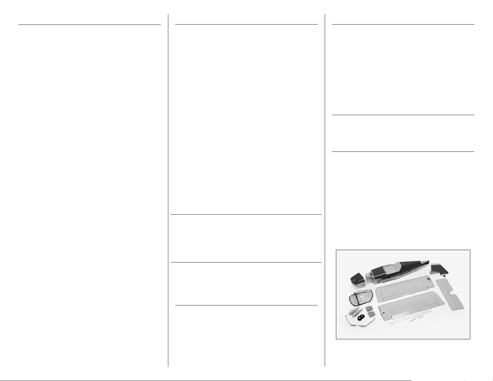
Table of Contents
Introduction
Using the Manual
Introduction ........................................................... 2
Important Warranty Information .............................. 2
Using the Manual ................................................... 2
Product Registration................................................ 2
Contents of Kit/Parts Layout .................................... 2
Recommended Radio Equipment ............................. 3
Recommended Standard Setup ................................ 3
Recommended High Power Setup ............................ 3
Optional Accessories .............................................. 3
Note on Lithium Polymer Batteries ........................... 3
Required Tools and Adhesives ................................. 3
Landing Gear Installation ........................................ 4
Tail Installation ....................................................... 4
Main Radio Installation ........................................... 7
Rudder and Elevator Linkage Installation .................. 9
Aileron Servo and Linkage Installation ................... 11
Joining the Wing Panels ....................................... 16
Fixed Flap Linkage Installation .............................. 18
Operational Flap Linkage Installation ..................... 20
Motor Installation ................................................. 23
Cowling Installation .............................................. 25
Wheel and Wheel Pant Installation ........................ 26
Canopy Detail Installation ..................................... 28
Wing Installation .................................................. 29
Control Throws..................................................... 30
Center of Gravity ................................................. 30
Preflight ............................................................... 31
Range Test Your Radio .......................................... 31
Flying Your RV-9 .................................................. 31
Safety Do’s and Don’ts for Pilots ............................ 32
Age Requirements ................................................ 32
Safety, Precautions and Warnings ......................... 32
Warranty Information ........................................... 32
Instructions for Disposal of WEEE by
Users in the European Union ............................ 34
2008 Official Academy of
Model Aeronautics Safety Code ....................... 34
Thank you for purchasing the E-flite® RV-9 450. The
sporty lines and spirited performance of the Van’s Aircraft
RV-9 has made it one of general aviation’s most popular
homebuilt aircraft. E-flite has perfectly captured the spirit
of this plane with this outstanding ARF that boasts true-toscale lines and, like its inspiration, is an absolute joy to
fly. To keep the scale lines unspoiled, E-flite has designed
the RV-9 with internal servo mounts that are concealed
from view. A classy red, yellow and blue UltraCote® trim
scheme, cockpit details and factory painted fiberlass cowl
further enhance the realism. You even have the option of
adding functioning flaps for exciting short field takeoffs
and landings.
In the air, the RV-9 450 offers a nice balance between
maneuverability and stability that will please both
intermediate and experienced pilots.
The RV-9 450 ARF is another addition to E-flite’s
outstanding line of electric RC aircraft and accessories.
E-flite uses top-quality engineering and materials in
everything they make, so you always get the maximum
level of value and fun. And E-flite backs all of its products
with the best customer service and support in the hobby so
your electric flight experience is always a positive one.
IMPRESSIVE SCALE DETAILS
Along with the true-to-scale outline of the wings and
fuselage, the RV-9 450 includes other scale touches such
as a detailed instrument panel, molded seatbacks and
room for two pilot figures (sold separately).
OPTIONAL FLAPS
For the ultimate in realism, you can add the optional flaps
and enjoy short field takeoff and landing performance.
They’re already cut and hinged for you. Just add the servo.
Important Warranty Information
This manual is divided into sections to help make
assembly easier to understand, and to provide breaks
between each major section. In addition, check boxes
have been placed next to each step to keep track
of its completion. Steps with a single circle () are
performed once, while steps with two circles ( )
indicate that the step will require repeating, such as for
a right or left wing panel, two servos, etc.
Remember to take your time and follow the directions.
Product Registration
Register your product online at:
www.e-fliterc.com/register/
Contents of Kit/Parts Layout
EFL2776 Fuselage
EFL2777 Hatch
EFL2778 Wing Set (Left and Right)
EFL2779 Tail Set
EFL2780 Cowl
EFL2781 Canopy
EFL2782 Spinner
EFL2783 Landing Gear (Left and Right)
EFL2784 Wheels and Axles
EFL2785 Wheel Pants (Left and Right)
EFL2786 Hardware Set
EFL2787 Pushrod Set
Please read our Warranty and Liability Limitations section
on Page 32 before building this product. If you as the
Purchaser or user are not prepared to accept the liability
associated with the use of this Product, you are advised
to return this Product immediately in new and unused
condition to the place of purchase.
2 E-flite RV-9 450 Assembly Manual
Page 3

Recommended Radio Equipment
Recommended Standard Setup
Required Tools and Adhesives
You will need a minimum 4-channel transmitter,
receiver, and four servos. You can also choose to
purchase a complete radio system. If you are using an
existing transmitter, just purchase the other required
equipment separately. We recommend the crystalfree, interference-free Spektrum™ DX6i 2.4GHz DSM®
6-channel system. If using your own transmitter, we
recommend the S75 Sub-Micro Servos from E-flite.
If you own the Spektrum DX6i radio, just add the
AR6200 DSM2
using flaps) E-flite S75 Sub-Micro Servos.
Transmitter and Receiver
SPM6600 DX6i 6-Channel DSM2 without
Or Purchase Separately
SPMAR6200 AR6200 AR6200
And
EFLRS75 S75 Sub Micro Servo
EFLREX12L 12-inch Lightweight Servo
EFLRYH3 3-inch Y-harness, Lightweight
EFLREX3L 3-inch Lightweight Servo
™
6-channel receiver and four (or five if
Servos, Mode 2
6-Channel Receiver Air
(4 required, 5 if using flaps)
Extension (2)
Extension (for optional flaps)
Motor Park 450 Brushless Outrunner
Motor, 890Kv (EFLM1400)
ESC 30-Amp Pro Switch-Mode BEC
Brushless ESC (EFLA1030)
Batteries 1800 3S 11.1V Li-Po battery
(EFLB18003S)
Propeller Electric Propeller, 10 x 7E
(APC10070E)
Recommended High Power Setup
Motor Park 480 Brushless Outrunner
Motor, 1020Kv (EFLM1505)
ESC 40-Amp Lite Pro Switch-Mode BEC
Brushless ESC (EFLA1040L)
Batteries 2100 3S 11.1V Li-Po battery
(EFLB21003S)
Prop Electric Propeller, 12 x 6E
(APC12060E)
Optional Accessories
EFLA110 Power Meter
EFLC3005 Celectra™ 1–3 Cell
Li-Po Charger
EFLC505 Intelligent 1- to 5-Cell
Balancing Charger
Note on Lithium Polymer Batteries
Tools & Equipment
Epoxy brush Felt-tipped pen
Low-tack tape Medium grit sandpaper
Mixing cup Mixing stick
Paper towel Pencil
Pin drill Pliers
Rubbing alcohol Ruler
Scissors Side cutters
Threadlock Waxed paper
Adjustable wrench
Phillips screwdriver: #00, #1
Drill bit: 1/16-inch (1.5mm)
Hobby knife with #11 blade
Nut driver or box wrench: 1/4-inch, 7mm
Hex wrench or ball driver: 1.5mm, 3/32-inch,
5/64-inch
String, dental floss or commercially available
servo connector (2)
Adhesives
30-minute Epoxy (HAN8002)
Canopy Glue (PAAPT56)
Medium CA (PAAPT02)
Thin CA (PAAPT08)
Threadlock
Thick CA
The Spektrum trademark is used with permission
of Bachmann Industries, Inc.
Lithium Polymer batteries are significantly
more volatile than alkaline or Ni-Cd/
Ni-MH batteries used in RC applications.
All manufacturer’s instructions and warnings
must be followed closely. Mishandling of
Li-Po batteries can result in fire. Always
follow the manufacturer’s instructions when
disposing of Lithium Polymer batteries.
During the course of building your model we suggest
that you use a soft base for the building surface.
Such things as a foam stand, large piece of bedding
foam or a thick bath towel will work well and help
protect the model from damage during assembly.
3E-flite RV-9 450 Assembly Manual
Page 4

Landing Gear Installation
Required Parts
Fuselage assembly Landing gear (left and right)
4-40 x 1/2-inch button head machine screw (4)
#4 washer (4)
Required Tools
Hex wrench or ball driver: 5/64-inch
Threadlock
1. Attach the main landing gear to the fuselage
using four 4-40 x 1/2-inch button head machine
screws and four #4 washers. Use a 5/64-inch hex
wrench or ball driver (not included) to tighten each
of the screws. Make sure to use threadlock on all
four screws so they do not vibrate loose.
Tail Installation
Required Parts
Fuselage assembly Vertical fin
Horizontal stabilizer 4-40 lock nut (2)
4-40 x 1/2-inch socket head bolt (2)
#4 washer (4) Control horn (2)
Control horn backplate (2)
Required Tools
Hex wrench or ball driver: 3/32-inch
Nut driver: 1/4-inch Threadlock
Thin CA Thick CA
Rubbing alcohol Paper towel
Felt-tipped pen
Hobby knife with #11 blade
Medium grit sandpaper
1. Locate the horizontal stabilizer. The top of the
stabilizer has the blind nut for attaching it to the
fuselage on the top side of the stabilizer.
2. Slide the stabilizer onto the threaded studs of the
vertical fin. Make sure the stabilizer is installed in
the correct direction by noting the position of the
blind nuts as described in the previous step. The
stabilizer should fit tightly against the vertical fin
when installed.
The main gear will angle back when
installed as shown in the photo.
4 E-flite RV-9 450 Assembly Manual
Page 5
3. Use two 4-40 lock nuts and two #4 washers to
secure the stabilizer to the vertical fin. Use a 1/4inch nut driver to tighten the nuts.
Make sure not to over-tighten the
nuts, damaging the stabilizer.
4. Fit the tail assembly to the fuselage. Make sure
to slide the tail post of the vertical fin into the slot at
the aft end of the fuselage. The assembly should fit
tightly in against the fuselage as shown.
5. Use two 4-40 x 1/2-inch socket head bolts and
two #4 washers to secure the tail assembly to the
fuselage. Make sure to use threadlock on both
screws before tightening them with a 3/32-inch
ball driver or hex wrench.
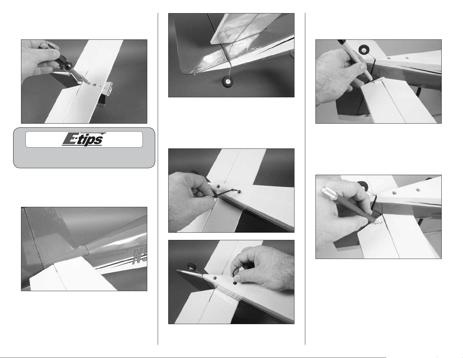
6. Insert the control horn into the pre-drilled holes in
the bottom of the elevator. Use a felt-tipped pen to
trace the outline of the control horn onto the elevator.
7. Remove the control horn. Use a hobby knife
with a new #11 blade to remove the covering from
inside the outline of the control horn drawn in the
previous step. Use care not to cut into the elevator
and damage the underlying wood.
5E-flite RV-9 450 Assembly Manual
Page 6
Use rubbing alcohol and a paper towel to remove
the line drawn on the bottom of the aileron
before installing the control horn permanently.
8. Use medium grit sandpaper to roughen the
surface of the control horn that will fit against the
elevator. Use rubbing alcohol and a paper towel
to remove any residue to provide the best possible
bond between the control horn and bare wood.
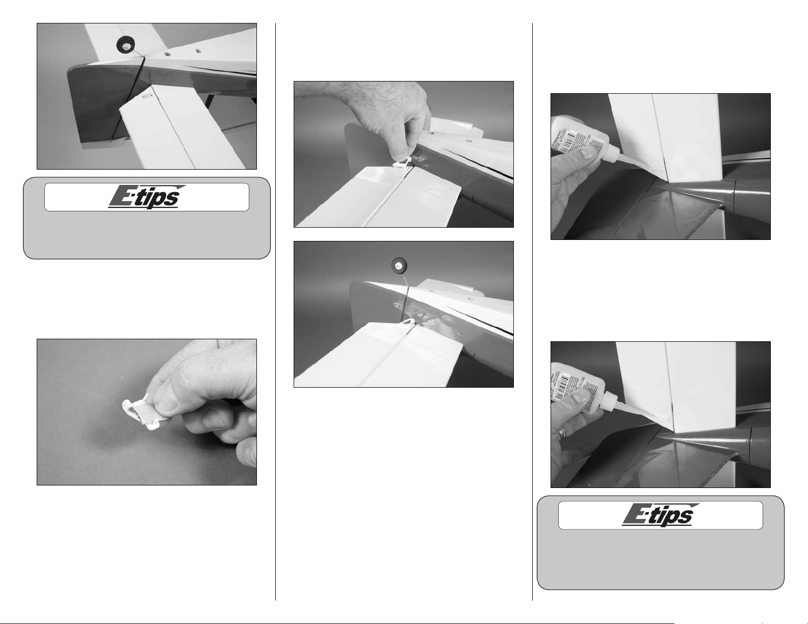
9. Apply a small amount of thick CA to the base
of the control horn. Insert the control horn in the
pre-drilled holes of the elevator as shown. Press the
control horn tight against the elevator.
10. Apply 2–3 drops of thin CA to each of the
control horn posts from the top of the control horn.
Make sure to apply the CA as close to the control
surface as possible while holding the control horn
tight against the elevator.
11. Before sliding the control horn backplate, make
sure the CA has fully cured or it may not slide tight
against the top of the stabilizer. After sliding the
backplate into position, apply 2–3 drops of thin CA
to each of the control horn posts as they protrude
through the backplate.
The control horn and backplate must be tight against
the control surface or there will be play between
the servo and surface. Use care when installing the
control horn to make sure it is done correctly.
6 E-flite RV-9 450 Assembly Manual
Page 7
12. Repeat Steps 6 through 11 to install the rudder
control horn. Note that the rudder control horn will
be on the opposite side, away from the elevator
control horn, when installed.
Main Radio Installation
Required Parts
Fuselage assembly Servo with hardware (2)
Receiver Hook and loop material
Required Tools
Pin drill Drill bit: 1/16-inch (1.5mm)
Pencil Phillips screwdriver: #1
Scissors Thin CA
1. Remove the canopy hatch from the fuselage by
lifting up at the rear of the fuselage. A magnet
holds the hatch to the fuselage at the rear. Slide
the hatch rearward to release the pin that holds the
hatch at the front. Set the canopy hatch aside.
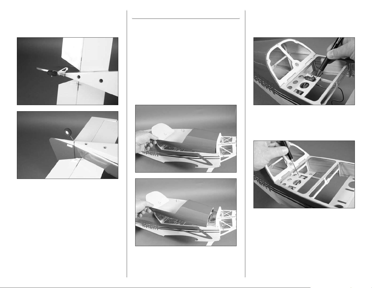
2. Position the elevator servo in the servo tray with
the output of the servo facing the front of aircraft.
Use a pencil to mark the location for the two servo
mounting screws on the servo tray.
3. Remove the servo from the servo tray. Use a
pin drill and 1/16-inch (1.5mm) drill bit to drill
two holes in the servo tray as marked in the
previous step.
7E-flite RV-9 450 Assembly Manual
Page 8
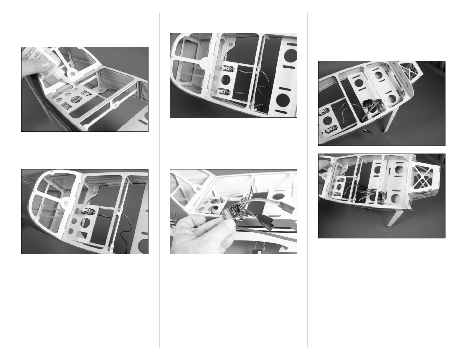
4. Apply 2-3 drops of thin CA in each hole to
harden the surrounding wood. This creates a harder
surface for the screws to bite into, making them
more secure when holding the servo in position.
5. Use the screws provided with the servo to secure
it in the servo tray. Tighten the screws using a #1
Phillips screwdriver.
6. Repeat Steps 2 through 5 to install the rudder
servo in the servo tray.
7. Plug the rudder and elevator servos into the
receiver. Plug a Y-harness into the aileron port of the
receiver. If you are installing the operational flaps,
you will also want to plug a 3-inch (76mm) servo
extension in the flap (or AUX) port of the receiver.
8. Use scissors to cut a small piece of hook and
loop material. Use the hook and loop to mount the
receiver on the battery tray as shown. Make sure
to position the receiver far enough forward that
the speed control can be plugged in during the
motor installation.
8 E-flite RV-9 450 Assembly Manual
Page 9

9. Use scissors to cut another small piece of hook
and loop material to mount the remote receiver in
the fuselage as shown.
Rudder and Elevator Linkage
Installation
Required Parts
Fuselage assembly Nylon pushrod connector (2)
Transmitter Flight Battery
Speed control or sperate Receiver battery
161/2-inch (420mm) elevator pushrod
173/4-inch (450mm) rudder pushrod
Pushrod connector backplate (2)
2mm x 5mm machine screw (2)
Required Tools
Pin drill Drill bit: 1/16-inch (1.5mm)
Ruler Phillips screwdriver: #00, #1
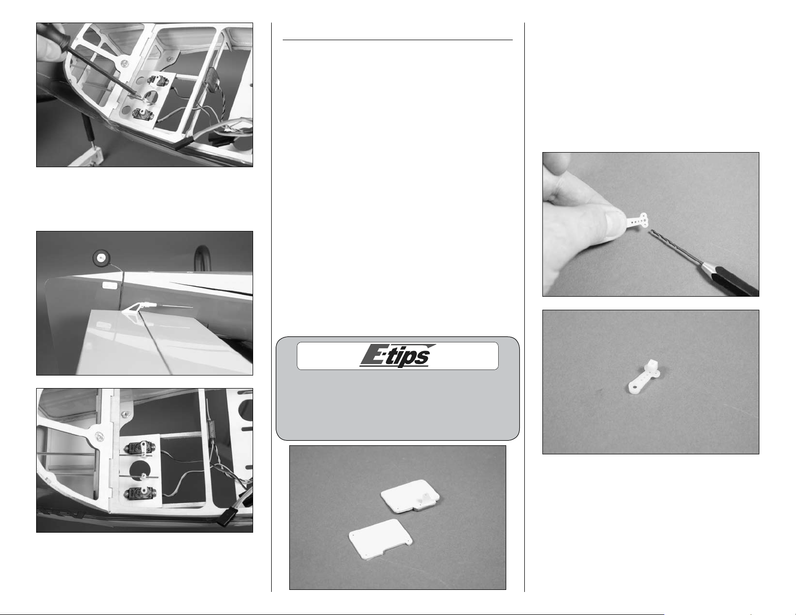
1. Use a #00 Phillips screwdriver to remove the
servo horns from the rudder and elevator servos.
2. Use a pin drill and 1/16-inch (1.5mm) drill bit to
enlarge the outer hole that is 1/2-inch (13mm) from
the center of the servo horn. Secure the pushrod
connector using a pushrod connector backplate.
3. Insert the nylon pushrod connector in the hole
enlarged in the last step. Use pliers to press the
backplate onto the connector.
4. Repeat Steps 2 and 3 to prepare a second
servo horn.
9E-flite RV-9 450 Assembly Manual
Page 10
5. Use the radio system to check the operation of
the rudder and elevator servos. It may be necessary
to bind the transmitter and receiver if you are using
a new receiver. Always select a blank model and
reset it to remove any programming or trim settings
when using a computer radio before starting the
linkage installation.
6. Use a #00 Phillips screwdriver to install the servo
horns to the servos. Make sure to position the horns
so they face each other as shown in the photo.
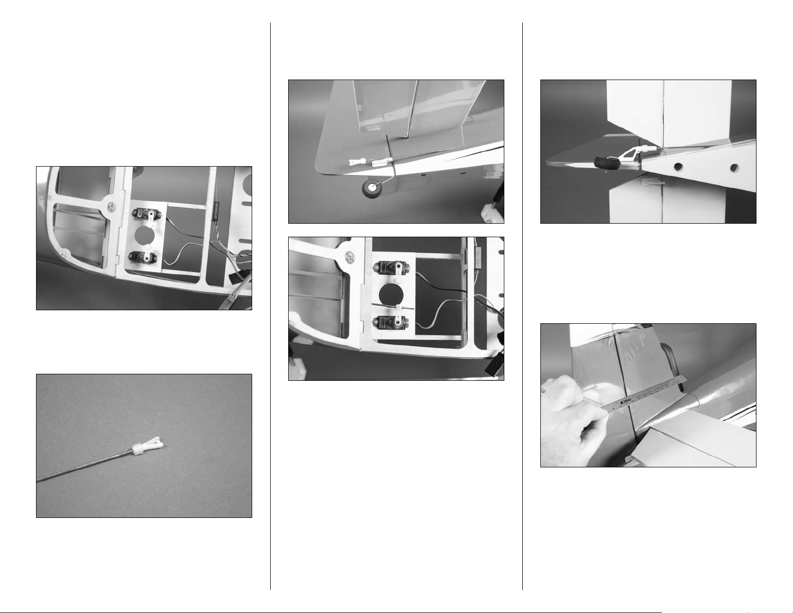
8. Slide the pushrod wire into the tube in the
fuselage that exits the same side as the rudder
control horn. Guide the wire through the pushrod
connector for the rudder servo inside the fuselage.
9. Connect the clevis to the outside hole of the
rudder control horn. Slide the clevis retainer over
the forks on the clevis to keep it from opening
accidentally.
10. Use a ruler to align the rudder with the fin.
With the radio system on and the rudder servo
centered, use a #1 Phillips screwdriver and a 2mm
x 5mm machine screw to secure the pushrod to the
pushrod connector. Use caution not to over-tighten
the screw and damage the pushrod connector.
7. Slide a clevis retainer onto a clevis. Thread the
clevis 16-turns onto the 173/4-inch (450mm) rudder
pushrod.
10 E-flite RV-9 450 Assembly Manual
Page 11
11. Use a 161/2-inch (406mm) elevator pushrod
wire and repeat Steps 7 through 10 for the
elevator linkage.
Aileron Servo and Linkage Installation
Required Parts
Wing panel (left and right)
Servo with hardware (2)
Nylon pushrod connector (2)
Pushrod connector backplate (2)
2mm x 5mm machine screw (2)
Aileron servo cover (right and left)
12-inch (305mm) servo extension (2)
2mm x 6mm sheet metal screw (8)
Speed control or separate receiver battery
Transmitter Flight battery
Control horn (2) Clevis (2)
Clevis retainer (2)
23/8-inch (60mm) aileron pushrod (2)
Required Tools
Pin drill Drill bit: 1/16-inch (1.5mm)
Pencil Phillips screwdriver: #00, #1
Medium CA Thin CA
Side cutters Hobby knife with #11 blade
Felt-tipped pen Rubbing alcohol
Paper towel Medium grit sandpaper
String, dental floss or commercially available servo
connector (2)
1. Use a #00 Phillips screwdriver to remove the
servo horns from the aileron servos. Use a pin
drill and 1/16-inch (1.5mm) drill bit to enlarge
the outer hole that is 1/2-inch (13mm) from the
center of the servo horn. Secure the pushrod
connector using a pushrod connector backplate.
Insert the nylon pushrod connector in the hole
enlarged in the last step. Use pliers to press the
backplate onto the connector. Prepare both aileron
servo horns at this time.
Before starting the aileron servo installation, make sure
to set aside the covers for the flap servo installation
(both operational and fixed) as shown in the photo
below. It is possible that you could accidentally prepare
two identical aileron servos using the flap servo cover.
11E-flite RV-9 450 Assembly Manual
Page 12

3. Place the servo on the aileron servo cover. Align
the servo horn with the edge of the cover as shown
in the first photo. The horn should also be centered
in the notch as shown in the second photo. Once
positioned, make sure the servo is not hanging
over the edge of the cover at the front or rear.
Use a pencil to mark the location of the two servo
mounting tabs on the servo cover.
4. Use medium grit sandpaper to scuff the two
servo mounting blocks as shown. This allows a
better bonding surface when gluing them to the
servo cover.
5. Use medium CA to glue the two blocks to the
servo cover as shown.
2. Plug the aileron servos into the Y-harness. Use
the radio system to center the servos. Use a #00
Phillips servo to install the servo horns back on
the aileron servos. Prepare a right and left aileron
servo at this time as shown.
12 E-flite RV-9 450 Assembly Manual
Page 13

6. Position the servo back between the blocks. Use
a pencil to mark the mounting locations for the
servo screws through the tabs on the servo and
onto the blocks.
8. Apply 2–3 drops of thin CA into each hole to
harden the surrounding wood. This provides a
harder surface, making the screws more secure
when installed.
10. Secure a 12-inch (305mm) servo extension
to the lead coming from the servo. Use string,
dental floss or a commercially available connector
to keep the extension and lead from unplugging
accidentally inside the wing.
7. Remove the servo and use a pin drill and 1/16-
inch (1.5mm) drill bit to drill the holes for the servo
mounting screws.
9. Use a #1 Phillips screwdriver and the screws
provided with the servo to secure it to the servo
mounting blocks.
11. Repeat Steps 3 through 10 to prepare the
second aileron servo.
13E-flite RV-9 450 Assembly Manual
Page 14

12. Check that you have a matching wing panel
and servo. The easiest way is one wing panel
has a “N” number, and the servo cover has the
matching text.
13. Tie the string that exits the wing at the servo
opening around the end of the servo extension.
Use the string to pull the extension through the
wing and through the hole at the center of the
wing as shown.
16. Use side cutters to trim the rear leg of a control
horn down to 3/16-inch (5mm).
14. Apply 2–3 drops of thin CA in each of the four
pre-drilled holes to harden the surrounding wood
for the servo cover screws.
17. Insert the control horn into the pre-drilled
holes in the bottom of the aileron. Use a felttipped pen to trace the outline of the control horn
onto the aileron.
15. Secure the servo cover to the wing using four
2mm x 6mm sheet metal screws. Use a #1 Phillips
screwdriver to tighten the screws.
14 E-flite RV-9 450 Assembly Manual
Page 15

18. Remove the control horn. Use a hobby knife
with a new #11 blade to remove the covering from
inside the outline of the control horn drawn in the
previous step. Use care not to cut into the aileron
and damage the underlying wood.
19. Use medium grit sandpaper to roughen the
surface of the control horn that will fit against the
aileron. Use rubbing alcohol and a paper towel
to remove any residue to provide the best possible
bond between the control horn and bare wood.
22. Slide the pushrod wire through the connector
on the servo. Attach the clevis to the outer hole
of the control horn and slide the clevis retainer
over the forks of the clevis to keep it from
opening accidentally.
Use rubbing alcohol and a paper towel to remove
the line drawn on the bottom of the aileron
before installing the control horn permanently.
20. Use medium CA to glue the control horn to
the aileron. Make sure to apply CA to both the
exposed wood on the aileron and to the legs of
the control horn. Press the horn tight against the
wing until the CA cures. Allow the CA to fully cure
before proceeding to the next step.
21. Slide a clevis retainer on a clevis, then thread
the clevis 16-turns onto a 23/8-inch (60mm) aileron
pushrod wire.
23. Align the aileron with the wing tip. With the
servo centered (you can use the radio to verify the
servo is still centered) use a 2mm x 5mm machine
screw and #1 Phillips screwdriver to secure the
pushrod wire to the pushrod connector.
15E-flite RV-9 450 Assembly Manual
Page 16

24. Repeat Steps 13 through 23 to install the
remaining aileron servo and linkage.
Joining the Wing Panels
Required Parts
Wing panel assembly (left and right)
Wing joiner Wing bolt plate
Wing dowel (2)
Required Tools
30-minute epoxy Rubbing alcohol
Mixing stick Mixing cup
Epoxy brush Paper towel
Low-tack tape Medium CA
Felt-tipped pen
Hobby knife with #11 blade
2. Slide the remaining wing panel on the wing
joiner. It should slide up tight against the first wing
panel with no gaps between them.
Please read through this section before mixing
any epoxy. You must be able to complete all the
steps before the epoxy begine to cure or you may
end up with a wing that will require replacing.
1. Locate the aluminum wing joiner. Slide the joiner
into one of the wing panels.
3. Separate the wing panels. Mix 1/2 ounce
(15mL) of 30-minute epoxy. Use a mixing stick to
apply epoxy in the wing tube of one wing panel.
Slide the joiner into the tube.
16 E-flite RV-9 450 Assembly Manual
Page 17

4. Use an epoxy brush to apply a thin layer of
epoxy to the exposed wood on the root rib of
the wing.
5. Use a mixing stick to apply epoxy in the tube of
the remaining wing panel. Use an epoxy brush to
apply a thin layer of epoxy to the exposed wood of
the root rib of the remaining wing panel.
6. Slide the wing panels tightly together. Epoxy
should ooze from the joint between the panels. If
not, you have not used enough epoxy and need to
apply more as described in Steps 3 through 5.
7. Use a paper towel and rubbing alcohol to
remove and excess epoxy from the outside of the
joint between the two wing panels.
8. Use low-tack tape to hold the two wing panels
together until the epoxy fully cures. Make sure
to wrap a piece of tape around the joint at the
leading and trailing edge to keep the panels in
alignment with each other while the epoxy cures.
Check the glue joint periodically while the epoxy is
curing. It is possible that some excess will run out of the
joint and will need to be wiped off with some alcohol.
9. Use medium CA to glue the wing dowels into the
pre-drilled holes in the leading edge of the wing.
Leave 1/4-inch (6mm) of the dowel exposed.
10. Position the wing bolt plate on the bottom of
the wing. Make sure to align the holes in the plate
with the holes in the wing. Use a felt-tipped pen to
transfer the outline of the plate onto the bottom of
the wing.
17E-flite RV-9 450 Assembly Manual
Page 18

Insert a 4-40 socket head bolt into each hole to
keep the plate in position while tracing the outline.
11. Use a hobby knife with a new #11 blade to
remove the covering 1/16-inch (1.5mm) inside the
line drawn in the last step.
12. Use medium CA to glue the wing bolt plate to
the bottom of the wing. Make sure the holes in the
plate are aligned with the holes in the wing before
the CA has cured.
You should now decide between fixed or operational
flaps. If you will be using operational flaps then you
should skip to that section on the next page.
Fixed Flap Linkage Installation
Required Parts
Wing assembly Flap linkage
Clevis (2) Clevis retainer (2)
Flap control horn (2) Fixed flap servo cover
Connector backplate Nylon pushrod connector
2mm x 5mm machine screw
2mm x 6mm sheet metal screw (4)
Required Tools
Pliers Phillips screwdriver: #1
Thin CA
1. Locate two clevises and clevis retainers. Slide the
retainers onto the clevises. Thread the clevises on
the flap linkage 16 turns.
Use rubbing alcohol and a paper towel to
remove the line drawn on the bottom of the
wing before installing the wing bolt plate.
2. Thread the flap control horns on the flap control
rods until the top of the horn is aligned with the top
of the threaded rod.
18 E-flite RV-9 450 Assembly Manual
Page 19

3. Connect the clevises from the flap linkage to the
flap control horns. Do not slide the clevis retainers
into position as the clevises may require adjustment
to position the flaps properly.
5. Prepare the fixed flap servo cover by inserting
a nylon pushrod connector in the hole of the
nylon horn on the cover. Use pliers to secure the
connector using a connector backplate.
7. With the aileron in the neutral position, position
the flap linkage so the flaps are aligned with the
ailerons. Check both the left and right flap as it
may be necessary to thread a clevis in or out to
align both flaps at the same time. Once aligned,
#1 Phillips screwdriver and a 2mm x 5mm
machine screw to secure the linkage to the pushrod
connector. Make sure to slide the clevis retainers
over the forks of the clevises to prevent them from
opening accidentally in flight.
4. Apply 2–3 drops of thin CA into each hole to
harden the surrounding wood. This provides a
harder surface, making the screws more secure
when installed.
6. Slide the linkage through the pushrod connector.
Position the servo cover and use d #1 Phillips
screwdriver to install the four 2mm x 8mm sheet
metal screws that secure the cover to the wing.
19E-flite RV-9 450 Assembly Manual
Page 20

Operational Flap Linkage Installation
Required Parts
Wing assembly Flap linkage
Clevis (2) Clevis retainer (2)
Flap control horn (2) Flap servo cover
Servo with hardware 2mm x 5mm machine screw
Transmitter Fuselage assembly
Flight battery
Speed control or separate receiver battery
Connector backplate
Nylon pushrod connector
2mm x 6mm sheet metal screw (4)
Required Tools
Pliers Phillips screwdriver: #1
Pin drill Drill bit: 1/16-inch (1.5mm)
Thin CA
3. Connect the clevises from the flap linkage to the
flap control horns. Do not slide the clevis retainers
into position as the clevises may require adjustment
to position the flaps properly.
5. Use a #00 Phillips screwdriver to remove the
servo horn from the flap servo. Use a pin drill
and 1/16-inch (1.5mm) drill bit to enlarge the
outer hole that is 1/2-inch (13mm) from the center
of the servo horn. Secure the pushrod connector
using a pushrod connector backplate. Insert the
nylon pushrod connector in the hole enlarged in
the last step. Use pliers to press the backplate onto
the connector.
1. Locate two clevises and clevis retainers. Slide the
retainers onto the clevises. Thread the clevises on
the flap linkage 16 turns.
2. Thread the flap control horns on the flap control
rods until the top of the horn is aligned with the top
of the threaded rod.
4. Apply 2–3 drops of thin CA into each hole to
harden the surrounding wood. This provides a
harder surface, making the screws more secure
when installed.
20 E-flite RV-9 450 Assembly Manual
Page 21

6. Plug the flap servos into the servo extension
from the receiver. Use the radio system to center the
servo. Use a #00 Phillips screwdriver to install the
servo horn back on the flap servo.
7. Place the servo on the flap servo cover. Align the
servo horn with the edge of the cover as shown in
the first photo. The horn should also be centered
in the notch as shown in the second photo. Once
positioned, make sure the servo is not hanging
over the edge of the cover at the front or rear.
Use a pencil to mark the location of the two servo
mounting tabs on the servo cover.
8. Use medium grit sandpaper to scuff the two
servo mounting blocks as shown. This allows a
better bonding surface when gluing them to the
servo cover.
9. Use medium CA to glue the two blocks to the
servo cover as shown.
10. Position the servo back between the blocks.
Use a pencil to mark the mounting locations for
the servo screws through the tabs on the servo and
onto the blocks.
11. Remove the servo and use a pin drill and
1/16-inch (1.5mm) drill bit to drill the holes for the
servo mounting screws.
21E-flite RV-9 450 Assembly Manual
Page 22

12. Apply 2–3 drops of thin CA into each hole
to harden the surrounding wood. This provides a
harder surface, making the screws more secure
when installed.
14. Pass the lead from the flap servo through the
hole in the wing as shown.
16. Use the radio to move the flap servo to the
up flap position. With the aileron in the neutral
position, place the flap linkage so the flaps are
aligned with the ailerons. Check both the left and
right flap, as it may be necessary to thread a clevis
in or out to align both flaps at the same time. Once
aligned, #1 Phillips screwdriver and a 2mm x 5mm
machine screw to secure the linkage to the pushrod
connector. Make sure to slide the clevis retainers
over the forks of the clevises to prevent them from
opening accidentally in flight.
13. Use a #1 Phillips screwdriver and the screws
provided with the servo to secure it to the servo
mounting blocks.
Place a piece of tape on the flap servo lead so it can
be easily differentiated from the aileron servo lead.
15. Slide the linkage through the pushrod connector.
Position the servo cover and use a #1 Phillips
screwdriver to install the four 2mm x 8mm sheet
metal screws that secure the cover to the wing.
17. Check the operation of the flaps at up, half and
down flap. You may need to use a computer radio
to set the positions according to the throws listed in
this manual.
FULL FLAP
22 E-flite RV-9 450 Assembly Manual
Page 23

HALF FLAP
UP FLAP
Motor Installation
Required Parts
Fuselage assembly Motor battery
#4 washer (4) Hook and loop material
Motor with hardware Transmitter
Speed control
Hook and loop strap
4-40 x 3/8-inch socket head screw (4)
Required Tools
Threadlock Scissors
Phillips screwdriver: #1
Hex wrench or ball driver: 3/32-inch
The installation for the Power 450 and Power 480
motors follow the same procedure. Make sure to
use a 30-amp speed control for the Power 450
and a 40-amp speed control for the Power 480.
1. Attach the X-mount to the motor using the
screws provided with the motor. Use a #1 Phillips
screwdriver to tighten the screws after placing a
drop of threadlock on each screw to prevent it from
vibrating loose.
2. Attach the motor to the firewall using four #4
washers and four 4-40 x 3/8-inch socket head
screws. Use a 3/32-inch ball driver or hex wrench
to tighten the screws. Make sure to use threadlock
on the screws to prevent them from vibrating loose.
We have shown three positions for the flaps. If you
are using a transmitter with only a 2-position switch,
then the half flap position would not be used. Flap
throws are covered at the end of the manual.
23E-flite RV-9 450 Assembly Manual
Page 24

The blind nuts in the firewall can be positioned
for a variety of motors. It may be necessary
to adjust them to fit your particular motor.
3. Pass the servo and battery leads from the speed
control through the hole in fuselage as shown. The
controller is held in place using hook and loop
material. Use scissors to cut the hook and loop
down to fit on the speed control. Plug the lead from
the speed control into the receiver at this time.
4. Connect the leads between the motor and speed
control. Make sure they are tucked away so they
will not interfere with the operation of the motor.
5. Install the battery in the fuselage as shown. Use
a hook and loop strap to secure the pack in the
fuselage. A small strip of hook and loop between
the battery and battery tray can be used to keep
the battery from moving fore and aft in the fuselage
during flight.
Use the battery to correctly balance your model. It
can be moved forward or rearward as necessary
to make changes to the balance of your model.
6. Check the operation of your motor at this time
using the radio system. The motor should spin
counterclockwise when viewed from the front
of the fuselage. If not, follow the speed control
manufacturer’s recommendations to reverse the
direction if necessary.
24 E-flite RV-9 450 Assembly Manual
Page 25

Cowling Installation
Required Parts
Fuselage assembly Cowling
Spinner cone Spinner backplate
Propeller Propeller adapter
Spinner screw (2) 2mm washer (4)
2mm x 8mm machine screw (4)
Required Tools
Low-tack tape Hobby knife with #11 blade
Felt-tipped pen Pin drill
Card stock Phillips screwdriver: #0
Drill bit: 1/16-inch (1.5mm)
1. Use a hobby knife and #11 blade to cut four
3/8-inch (8mm) wide and 2-inch (52mm) long
pieces of cardstock. Make a hole near the end of
each piece. Align the hole with the insert in the
fuselage and tape the cardstock to the fuselage
using low-tack tape.
2. Slide the propeller adapter through the hole in
the spinner backplate. The propeller is then placed
on the adapter, then the propeller adapter nut
threaded on. Do not tighten the nut: It only needs to
hold the assembly together at this time.
3. Slide the cowling on the fuselage. Make sure
it fits the outside of the fuselage. The propeller
assembly from the previous step is then slid into
position on the motor shaft.
4. Position the cowling so there is a 1/16- to 1/8-
inch (2mm to 3mm) gap between the cowling and
spinner backplate. Also make sure the cowling is
aligned and centered with the backplate. Use a felttipped pen to mark the locations for the four cowl
mounting screws on the cowl.
Use a 2mm x 8mm machine screw to help in aligning
the hole in the cardstock with the insert in the fuselage.
25E-flite RV-9 450 Assembly Manual
Page 26

Make sure the trim on the cowl and fuselage
are aligned before marking the cowl.
7. Remove the tape and cardstock from the
fuselage. Use four 2mm x 8mm machine screws
and four 2mm washers to secure the cowl to the
fuselage. Use your #0 Phillips screwdriver to tighten
those screws.
Wheel and Wheel Pant Installation
Required Parts
Fuselage assembly Wheel pant (right and left)
Wheel axle with nut (2)
Wheel, 13/4-inch (42mm) (2)
5/64-inch (2mm) wheel collar with setscrew (4)
2mm x 8mm sheet metal screw (4)
Required Tools
Adjustable wrench Phillips screwdriver: #1
Hex wrench or ball driver: 1.5mm
Nut driver or box wrench: 7mm
1. Remove the wheel collars and nut from the axle.
You may need to use a 1.5mm hex wrench or ball
driver to loosen the setscrews that keep the wheel
collars attached to the axle.
5. Remove the propeller assembly from the motor.
Remove the cowling from the fuselage. Use a pin
drill and 1/16-inch (1.5mm) drill bit to drill the
four holes through the cowl for mounting screws.
8. Place the propeller adapter on the motor shaft.
Follow the instructions provided with your motor
to tighten the propeller adapter nut. Position the
spinner cone on the backplate. The cone will key
into the backplate when installed. Make sure there
is clearance between the openings of the cone and
propeller. If not it may be necessary to reposition
the propeller by loosening the nut and moving the
propeller. Use a #0 Phillips screwdriver to tighten
the spinner mounting screws.
26 E-flite RV-9 450 Assembly Manual
Page 27

2. Use an adjustable wrench and 7mm nut driver or
box wrench to secure the axle to the landing gear.
3. Install the first wheel collar so it is 1/16-inch
(1.5mm) away from the edge of the outer axle nut
as shown.
4. Slide the wheel pant over the axle. The wheel
will need to be placed on the exle, then a second
wheel collar installed. Use a 1.5mm hex wrench or
ball driver to lower the wheel collar into position. If
you tighten the setscrew it will keep it from falling
into the wheel pant accidentally. The position of the
wheel collar will be adjusted once the wheel pant is
secured to the landing gear.
5. Use two 2mm x 8mm sheet metal screws
to secure the wheel pant to the landing gear.
The screws will require the use of a #1 Phillips
screwdriver to tighten them. Make sure the wheel
pant is tight against the landing gear before
starting the screws.
6. Use your 1.5mm hex wrench or ball driver to
tighten the setscrew to secure the outer wheel collar.
Make sure the wheel can rotate freely on the axle.
27E-flite RV-9 450 Assembly Manual
Page 28

7. Repeat Steps 1 though 6 to install the remaining
wheel and wheel pant.
Canopy Detail Installation
Required Parts
Fuselage assembly Canopy hatch
Canopy Seat back (2)
Pilot (optional) (EFLA156)
Required Tools
Canopy glue Waxed paper
Medium CA Low-tack tape
1. Locate the two seat backs. Use medium CA to
glue the seat backs to the canopy hatch as shown
in the photo below.
2. Use medium CA to glue the pilot (optional) to
the canopy hatch as shown.
3. Place the canopy hatch on the fuselage. Make
sure to place a piece of waxed paper or part of a
bag from the packaging of your model between the
hatch and fuselage so when the canopy is glued
to the hatch it won’t accidentally be glued to the
fuselage. Make sure that the hatch is fully seated on
the fuselage and the magnet in engaged during this
step. If it is not seated and engaged it could cause
your hatch to fit improperly or not engage once the
canopy is glued on.
28 E-flite RV-9 450 Assembly Manual
Page 29

4. Use canopy glue to secure the canopy to the
hatch. Use low-tack tape to keep the canopy in
position on the fuselage until the glue fully cures.
Wing Installation
Required Parts
Fuselage assembly Wing assembly
#4 washer (2)
4-40 x 1-inch socket head screw (2)
Required Tools
Hex wrench or ball driver: 3/32-inch
1. Remove the hatch from the fuselage. Position the
wing on the bottom of the fuselage. Slide the wing
forward so the dowels in the leading edge go into
the appropriate holes in the fuselage.
3. Plug the aileron servos into the Y-harness coming
from the receiver. If you are using flaps, plug the
flap servo lead into the 3-inch (76mm) extension
coming from the receiver.
2. Check to make sure the leads for the aileron
servos (and flap servo) are inside the fuselage.
The wing is held in position using two 4-40 x
1-inch socket head screws and two #4 washers.
Use a 3/32-inch ball driver or hex wrench to
tighten the screws.
29E-flite RV-9 450 Assembly Manual
Page 30

Control Throws
1. Turn on the transmitter and receiver of your
model. Check the movement of the rudder using
the transmitter. When the stick is moved right,
the rudder should also move right. Reverse the
direction of the servo at the transmitter if necessary.
2. Check the movement of the elevator with the
radio system. Moving the elevator stick toward the
bottom of the transmitter will make the airplane
elevator move up.
3. Check the movement of the ailerons with the
radio system. Moving the aileron stick right will
make the right aileron move up and the left aileron
move down.
4. Use a ruler to adjust the throw of the elevator,
ailerons and rudder.
Aileron High Rate Exponential
Up 9/16-inch (14mm) 15%
Down 9/16-inch (14mm) 15%
Aileron Low Rate
Up 3/8-inch (10mm) 10%
Down 3/8-inch (10mm) 10%
Elevator High Rate
Up 3/4-inch (20mm) 15%
Down 3/4-inch (20mm) 15%
Elevator Low Rate
Up 5/8-inch (15mm) 10%
Down 5/8-inch (15mm) 10%
Rudder High Rate
Left 1
Right 19/16-inch (40mm) 15%
Rudder Low Rate
Left 1-inch (25mm) 10%
Right 1-inch (25mm) 10%
Flap Throw
Up Align with wing trailing edge
Center 5/16-inch (8mm)
Down 5/8-inch (15mm)
9
/16-inch (40mm) 15%
Center of Gravity
An important part of preparing the aircraft for flight is
properly balancing the model.
Caution: Do not inadvertently skip this step!
The recommended Center of Gravity (CG) location
for your model is 2- to 21/4-inches (50–58mm) back
from the leading edge of the wing at the center. Make
sure to measure from the farthest point forward for
accuracy. Mark the location for the Center of Gravity
on the top of the wing next to the fuselage as shown.
Adjust components as necessary so the model hangs
level or slightly nose down. This is the correct balance
point for your model. You might find that you need to
shift the battery slightly to either the front or back of
the fuselage to achieve the correct balance.
Measurements are taken at the inner or
widest point on the control surface.
After the first flights, the CG position can be adjusted
for your personal preference.
These are general guidelines measured from our own
flight tests. You can experiment with higher rates to
match your preferred style of flying.
Travel Adjust, Sub Trim and Dual Rates are
not listed and should be adjusted according
to each individual model and preference.
30 E-flite RV-9 450 Assembly Manual
Page 31

Preflight
Range Test Your Radio
Flying Your RV-9
Check Your Radio
Before going to the field, be sure that your batteries
are fully charged per the instructions included with
your radio. Charge both the transmitter and receiver
pack for your airplane. Use the recommended charger
supplied with your particular radio system, following
the instructions provided with the radio. In most cases,
the radio should be charged the night before going
out flying.
Before each flying session, be sure to range check your
radio. See your radio manual for the recommended
range and instructions for your radio system. Each
radio manufacturer specifies different procedures for
their radio systems. Next, start the motor. With the
model securely anchored, check the range again.
The range test should not be significantly affected. If
it is, don’t attempt to fly! Have your radio equipment
checked out by the manufacturer.
Note: Keep loose items that can get entangled
in the propeller away from the prop. These
include loose clothing, or other objects such as
pencils and screwdrivers. Especially keep your
hands away from the propeller.
1. Before each flying session, be sure to range
check your radio. This is accomplished by turning
on your transmitter with the antenna collapsed.
Turn on the receiver in your airplane. With
your airplane on the ground and the engine
running, you should be able to walk 30 paces
(approximately 100 feet) away from your airplane
and still have complete control of all functions.
If not, don’t attempt to fly! Have your radio
equipment checked out by the manufacturer.
2. Double-check that all controls (aileron, elevator,
rudder and throttle) move in the correct direction.
3. Be sure that your transmitter batteries are
fully charged, per the instructions included with
your radio.
Flying the RV-9 is a pleasure. Takeoffs are easy as
well as landings. Loops and rolls are as easy as
pushing the control stick in the desired direction with
the control throws listed in the manual. Flight times of
8–10 minutes with the recommended LiPo battery are
common.
The RV-9 is capable of flying in light winds up to
10 mph, and can do just about any basic aerobatic
manuever you would like to accomplish. The RV-9
carries itself very well on final approach. A descending
approach during final is all that is required to maintain
airspeed. Touchdowns are easily accomplished in a
three-point state. You will enjoy the added ability to
vary the landing speed even more when using the
optional flaps.
We hope you enjoy flying your RV-9 as much
as we do.
Happy Landings!
Double-check that all controls (aileron, elevator, rudder
and throttle) move in the correct direction.
Check the radio installation and make sure all the
control surfaces are moving correctly (i.e. the correct
direction and with the recommended throws). Test run
the motor and make sure it transitions smoothly from
off to full throttle and back. Also ensure the engine is
installed according to the manufacturer’s instructions,
and it will operate consistently.
Check all the control horns, servo horns, and clevises
to make sure they are secure and in good condition.
Repair or replace any items that would be considered
questionable. Failure of any of these components in
flight would mean the loss of your aircraft.
31E-flite RV-9 450 Assembly Manual
Page 32

Safety Do’s and Don’ts for Pilots
Age Requirements
Warranty Information
• Checkallcontrolsurfacespriortoeachtakeoff.
• Donotflyyourmodelnearspectators,parking
areas or any other area that could result in injury
to people or damage of property.
• Donotflyduringadverseweatherconditions.
Poor visibility can cause disorientation and loss
of control of your aircraft. Strong winds can
cause similar problems.
• Donottakechances.Ifatanytimeduringflight
you observe any erratic or abnormal operation,
land immediately and do not resume flight until
the cause of the problem has been ascertained
and corrected. Safety can never be taken lightly.
• Donotflynearpowerlines.
Age Recommendation: 14 years or over. This is not
a toy. This product is not intended for use by children
without direct adult supervision.
Safety, Precautions and Warnings
As the user of this product, you are solely responsible
for operating it in a manner that does not endanger
yourself and others or result in damage to the product
or the property of others.
Carefully follow the directions and warnings for
this and any optional support equipment (chargers,
rechargeable battery packs, etc.) that you use.
This model is controlled by a radio signal that is
subject to interference from many sources outside
your control. This interference can cause momentary
loss of control so it is necessary to always keep a safe
distance in all directions around your model, as this
margin will help to avoid collisions or injury.
•Alwaysoperateyourmodelinanopenareaaway
from cars, traffic or people.
•Avoidoperatingyourmodelinthestreetwhere
injury or damage can occur.
•Neveroperatethemodeloutintothestreetor
populated areas for any reason.
•Neveroperateyourmodelwithlowtransmitter
batteries.
•Carefullyfollowthedirectionsandwarningsfor
this and any optional support equipment (chargers,
rechargeable battery packs, etc.) that you use.
•Keepallchemicals,smallpartsandanything
electrical out of the reach of children.
•Moisturecausesdamagetoelectronics.Avoidwater
exposure to all equipment not specifically designed
and protected for this purpose.
WARRANTY PERIOD
Exclusive Warranty- Horizon Hobby, Inc., (Horizon)
warranties that the Products purchased (the “Product”)
will be free from defects in materials and workmanship
at the date of purchase by the Purchaser.
LIMITED WARRANTY
(a) This warranty is limited to the original Purchaser
(“Purchaser”) and is not transferable. REPAIR
OR REPLACEMENT AS PROVIDED UNDER THIS
WARRANTY IS THE EXCLUSIVE REMEDY OF THE
PURCHASER. This warranty covers only those Products
purchased from an authorized Horizon dealer. Third
party transactions are not covered by this warranty.
Proof of purchase is required for warranty claims.
Further, Horizon reserves the right to change or modify
this warranty without notice and disclaims all other
warranties, express or implied.
(b) Limitations- HORIZON MAKES NO WARRANTY
OR REPRESENTATION, EXPRESS OR IMPLIED,
ABOUT NON-INFRINGEMENT, MERCHANTABILITY
OR FITNESS FOR A PARTICULAR PURPOSE OF THE
PRODUCT. THE PURCHASER ACKNOWLEDGES
THAT THEY ALONE HAVE DETERMINED THAT THE
PRODUCT WILL SUITABLY MEET THE REQUIREMENTS
OF THE PURCHASER’S INTENDED USE.
(c) Purchaser Remedy- Horizon’s sole obligation
hereunder shall be that Horizon will, at its option,
(i) repair or (ii) replace, any Product determined
by Horizon to be defective. In the event of a defect,
these are the Purchaser’s exclusive remedies. Horizon
reserves the right to inspect any and all equipment
involved in a warranty claim. Repair or replacement
decisions are at the sole discretion of Horizon.
This warranty does not cover cosmetic damage or
damage due to acts of God, accident, misuse, abuse,
negligence, commercial use, or modification of or
to any part of the Product. This warranty does not
cover damage due to improper installation, operation,
maintenance, or attempted repair by anyone other
than Horizon. Return of any goods by Purchaser must
be approved in writing by Horizon before shipment.
32 E-flite RV-9 450 Assembly Manual
Page 33

DAMAGE LIMITS
QUESTIONS, ASSISTANCE, AND REPAIRS
NON-WARRANTY REPAIRS
HORIZON SHALL NOT BE LIABLE FOR SPECIAL,
INDIRECT OR CONSEQUENTIAL DAMAGES, LOSS
OF PROFITS OR PRODUCTION OR COMMERCIAL
LOSS IN ANY WAY CONNECTED WITH THE
PRODUCT, WHETHER SUCH CLAIM IS BASED IN
CONTRACT, WARRANTY, NEGLIGENCE, OR STRICT
LIABILITY. Further, in no event shall the liability of
Horizon exceed the individual price of the Product on
which liability is asserted. As Horizon has no control
over use, setup, final assembly, modification or misuse,
no liability shall be assumed nor accepted for any
resulting damage or injury. By the act of use, setup or
assembly, the user accepts all resulting liability.
If you as the Purchaser or user are not prepared
to accept the liability associated with the use of
this Product, you are advised to return this Product
immediately in new and unused condition to the place
of purchase.
Law: These Terms are governed by Illinois law (without
regard to conflict of law principals).
SAFETY PRECAUTIONS
This is a sophisticated hobby Product and not a toy.
It must be operated with caution and common sense
and requires some basic mechanical ability. Failure to
operate this Product in a safe and responsible manner
could result in injury or damage to the Product or
other property. This Product is not intended for use by
children without direct adult supervision. The Product
manual contains instructions for safety, operation and
maintenance. It is essential to read and follow all
the instructions and warnings in the manual, prior to
assembly, setup or use, in order to operate correctly
and avoid damage or injury.
Your local hobby store and/or place of purchase
cannot provide warranty support or repair. Once
assembly, setup or use of the Product has been
started, you must contact Horizon directly. This will
enable Horizon to better answer your questions
and service you in the event that you may need any
assistance. For questions or assistance, please direct
your email to productsupport@horizonhobby.com,
or call 877.504.0233 toll free to speak to a service
technician.
INSPECTION OR REPAIRS
If this Product needs to be inspected or repaired,
please call for a Return Merchandise Authorization
(RMA). Pack the Product securely using a shipping
carton. Please note that original boxes may be
included, but are not designed to withstand the rigors
of shipping without additional protection. Ship via a
carrier that provides tracking and insurance for lost
or damaged parcels, as Horizon is not responsible
for merchandise until it arrives and is accepted at our
facility. A Service Repair Request is available at www.
horizonhobby.com on the “Support” tab. If you do
not have internet access, please include a letter with
your complete name, street address, email address
and phone number where you can be reached during
business days, your RMA number, a list of the included
items, method of payment for any non-warranty
expenses and a brief summary of the problem.
Your original sales receipt must also be included for
warranty consideration. Be sure your name, address,
and RMA number are clearly written on the outside of
the shipping carton.
WARRANTY INSPECTION AND REPAIRS
To receive warranty service, you must include your
original sales receipt verifying the proof-of-purchase
date. Provided warranty conditions have been met,
your Product will be repaired or replaced free of
charge. Repair or replacement decisions are at the sole
discretion of Horizon Hobby.
Should your repair not be covered by warranty the
repair will be completed and payment will be required
without notification or estimate of the expense unless
the expense exceeds 50% of the retail purchase cost.
By submitting the item for repair you are agreeing
to payment of the repair without notification. Repair
estimates are available upon request. You must include
this request with your repair. Non-warranty repair
estimates will be billed a minimum of 1/2 hour of
labor. In addition you will be billed for return freight.
Please advise us of your preferred method of payment.
Horizon accepts money orders and cashiers checks,
as well as Visa, MasterCard, American Express, and
Discover cards. If you choose to pay by credit card,
please include your credit card number and expiration
date. Any repair left unpaid or unclaimed after 90
days will be considered abandoned and will be
disposed of accordingly. Please note: non-warranty
repair is only available on electronics and model
engines.
United States:
Electronics and engines requiring inspection or repair
should be shipped to the following address:
Horizon Service Center
4105 Fieldstone Road
Champaign, Illinois 61822
All other Products requiring warranty inspection or
repair should be shipped to the following address:
Horizon Product Support
4105 Fieldstone Road
Champaign, Illinois 61822
Please call 877-504-0233 or e-mail us at
productsupport@horizonhobby.com with any questions
or concerns regarding this product or warranty.
33E-flite RV-9 450 Assembly Manual
Page 34

United Kingdom:
Electronics and engines requiring inspection or repair
should be shipped to the following address:
Horizon Hobby UK
Units 1-4 Ployters Rd
Staple Tye
Harlow, Essex
CM18 7NS
United Kingdom
Please call +44 (0) 1279 641 097 or e-mail us at
sales@horizonhobby.co.uk with any questions or
concerns regarding this product or warranty.
Germany:
Electronics and engines requiring inspection or repair
should be shipped to the following address:
Instructions for Disposal of WEEE by
Users in the European Union
This product must not be disposed of with other waste.
Instead, it is the user’s responsibility to dispose of their
waste equipment by handing it over to a designated
collection point for the recycling of waste electrical
and electronic equipment. The separate collection
and recycling of your waste equipment at the time
of disposal will help to conserve natural resources
and ensure that it is recycled in a manner that
protects human health and the environment. For more
information about where you can drop off your waste
equipment for recycling, please contact your local city
office, your household waste disposal service or where
you purchased the product.
2008 Official Academy of Model
Aeronautics Safety Code
GENERAL
1. A model aircraft shall be defined as a nonhuman-carrying device capable of sustained
flight in the atmosphere. It shall not exceed
limitations established in this code and is
intended to be used exclusively for recreational
or competition activity.
2. The maximum takeoff weight of a model aircraft,
including fuel, is 55 pounds, except for those
flown under the AMA Experimental Aircraft
Rules.
3. I will abide by this Safety Code and all rules
established for the flying site I use. I will not
willfully fly my model aircraft in a reckless and/
or dangerous manner.
Horizon Technischer Service
Hamburger Strasse 10
25335 Elmshorn
Germany
Please call +49 4121 46199 66 or e-mail us at
service@horizonhobby.de with any questions or
concerns regarding this product or warranty
4. I will not fly my model aircraft in sanctioned
events, air shows, or model demonstrations until
it has been proven airworthy.
5. I will not fly my model aircraft higher than
approximately 400 feet above ground level,
when within three (3) miles of an airport without
notifying the airport operator. I will yield the
right-of-way and avoid flying in the proximity
of full-scale aircraft, utilizing a spotter when
appropriate.
6. I will not fly my model aircraft unless it is
identified with my name and address, or AMA
number, inside or affixed to the outside of the
model aircraft. This does not apply to model
aircraft flown indoors.
7. I will not operate model aircraft with metal-blade
propellers or with gaseous boosts (other than
air), nor will I operate model aircraft with fuels
containing tetranitromethane or hydrazine.
34 E-flite RV-9 450 Assembly Manual
Page 35

8. I will not operate model aircraft carrying
pyrotechnic devices which explode burn, or
propel a projectile of any kind. Exceptions
include Free Flight fuses or devices that burn
producing smoke and are securely attached to
the model aircraft during flight. Rocket motors
up to a G-series size may be used, provided
they remain firmly attached to the model aircraft
during flight. Model rockets may be flown in
accordance with the National Model Rocketry
Safety Code; however, they may not be launched
from model aircraft. Officially designated AMA
Air Show Teams (AST) are authorized to use
devices and practices as defined within the Air
Show Advisory Committee Document.
9. I will not operate my model aircraft while under
the influence of alcohol or within eight (8) hours
of having consumed alcohol.
10. I will not operate my model aircraft while using
any drug which could adversely affect my ability
to safely control my model aircraft.
11. Children under six (6) years old are only allowed
on a flightline or in a flight area as a pilot or
while under flight instruction.
12. When and where required by rule, helmets
must be properly worn and fastened. They must
be OSHA, DOT, ANSI, SNELL or NOCSAE
approved or comply with comparable standards.
RADIO CONTROL
1. All model flying shall be conducted in a manner
to avoid over flight of unprotected people.
2. I will have completed a successful radio
equipment ground-range check before the first
flight of a new or repaired model aircraft.
3. I will not fly my model aircraft in the presence of
spectators until I become a proficient flier, unless I
am assisted by an experienced pilot.
4. At all flying sites a line must be established,
in front of which all flying takes place. Only
personnel associated with flying the model
aircraft are allowed at or in front of the line. In
the case of airshows demonstrations straight line
must be established. An area away from the line
must be maintained for spectators. Intentional
flying behind the line is prohibited.
5. I will operate my model aircraft using only
radio-control frequencies currently allowed by
the Federal Communications Commission (FCC).
Only individuals properly licensed by the FCC
are authorized to operate equipment on Amateur
Band frequencies.
6. I will not knowingly operate my model aircraft
within three (3) miles of any preexisting flying
site without a frequency-management agreement.
A frequency management agreement may be
an allocation of frequencies for each site, a
day-use agreement between sites, or testing
which determines that no interference exists.
A frequency-management agreement may
exist between two or more AMA chartered
clubs, AMA clubs and individual AMA
members, or individual AMA members.
Frequency-management agreements, including
an interference test report if the agreement
indicates no interference exists, will be signed
by all parties and copies provided to AMA
Headquarters.
7. With the exception of events flown under official
AMA rules, no powered model may be flown
outdoors closer than 25 feet to any individual,
except for the pilot and located at the flightline.
8. Under no circumstances may a pilot or other
person touch a model aircraft in flight while it is
still under power, except to divert it from striking
an individual.
9. Radio-controlled night flying is limited to lowperformance model aircraft (less than 100 mph).
The model aircraft must be equipped with a
lighting system which clearly defines the aircraft’s
attitude and direction at all times.
10. The operator of a radio-controlled model
aircraft shall control it during the entire flight,
maintaining visual contact without enhancement
other than by corrective lenses that are
prescribed for the pilot. No model aircraft shall
be equipped with devices which allow it to be
flown to a selected location which is beyond the
visual range of the pilot.
RV-9 Safe Operating Recommendations
- Inspect your model before every flight to make
certain it is airworthy.
- Be aware of any other radio frequency user who
may present an interference problem.
- Always be courteous and respectful of other
users of your selected flight area.
- Choose an area clear of obstacles and large
enough to safely accommodate your flying
activity.
- Make certain this area is clear of friends and
spectators prior to launching your aircraft.
- Be aware of other activities in the vicinity of your
flight path that could cause potential conflict.
- Carefully plan your flight path prior to launch.
- Abide by any and all established AMA National
Model Aircraft Safety Code.
35E-flite RV-9 450 Assembly Manual
Page 36

Printed 04/09
© 2009 Horizon Hobby, Inc.
4105 Fieldstone Road
Champaign, Illinois 61822
(877) 504-0233
horizonhobby.com
E-fliteRC.com
15391.1
 Loading...