

E-flite Nieuport 17 250 ARF User Manual
Nieuport 17 250 Slow Flyer
Specifications
Wingspan: 34.5 in (875mm)
Wing Area: 295 sq in (19.03 sq dm)
Length: 24 in (610mm)
Weight w/o Battery: 8–8.5 oz (227–240 g)
Weight w/Battery: 6.75–7.25 oz (190–205 g)
Assembly Manual
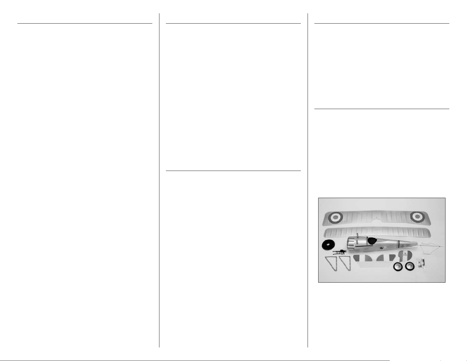
Table of Contents
Introduction
Using the Manual
Specifications ......................................................... 1
Introduction ........................................................... 2
Important Information Regarding
Warranty Information ........................................ 2
Using the Manual ................................................... 2
Contents of Kit/Parts Layout .................................... 2
Recommended Radio Equipment ............................. 3
Required Tools and Adhesives ................................. 3
Brushless Outrunner Setup ...................................... 3
Optional Accessories .............................................. 3
Note on Lithium Polymer Batteries ........................... 3
Warning ................................................................ 3
Servo Installation .................................................... 3
Stabilizer Installation .............................................. 6
Rudder Installation ................................................. 8
Connecting the Linkages ....................................... 11
Motor and Speed Control Installation .................... 12
Bottom Wing and Landing Gear Installation ........... 16
Top Wing and Outer Strut Installation .................... 17
Rigging Installation ............................................... 18
Scale Accessory Installation .................................. 21
Control Throws..................................................... 22
Center of Gravity ................................................. 22
Preflight ............................................................... 23
Range Test Your Radio .......................................... 23
Flying Your Nieuport 17 Slow Flyer ....................... 23
Safety, Precautions and Warnings ......................... 24
Safety Do’s and Don’ts for Pilots ............................ 24
Warranty Information ........................................... 24
Instructions for Disposal of WEEE by
Users in the European Union ............................ 26
2008 Official Academy of
Model Aeronautics Safety Code ....................... 26
The Nieuport 17 was designed by the French as a
single-seat fighter biplane in World War I. It was a
very maneuverable aircraft and many British and
French pilots began their careers with a Nieuport 17.
E-flite’s Nieuport 17 Slow Flyer is an electric indoor
version of the French biplane fighter. It’s the third in
a line of E-flite slow flyers and boasts a low weight
and a more majestic type of slow flight thanks to the
biplane design and reduced wing loading. So you
can get to flying faster, the Nieuport 17 comes with
many prefinished details including wood interplane
and cabane struts, molded cowling, a dummy motor,
a prepainted trim scheme and decals that are already
applied.
The E-flite Nieuport 17 Slow Flyer 250 ARF is a
fantastic flying foamie with outstanding slow speed
characteristics—making it perfect for indoor flight.
Important Information
Regarding Warranty Information
Please read our Warranty and Liability Limitations
section on Page 24 before building this product. If you
as the Purchaser or user are not prepared to accept the
liability associated with the use of this Product, you are
advised to return this Product immediately in new and
unused condition to the place of purchase.
This manual is divided into sections to help make
assembly easier to understand, and to provide breaks
between each major section. In addition, check boxes
have been placed next to each step to keep track
of its completion. Steps with a single circle () are
performed once, while steps with two circles ( )
indicate that the step will require repeating, such as for
a right or left wing panel, two servos, etc.
Remember to take your time and follow the directions.
Contents of Kit/Parts Layout
Replacement Parts
EFL1951 Wing Set
EFL1952 Fuselage Set
EFL1953 Tail Set
EFL1954 Cowling
EFL1955 Wheel Set
EFL1956 Landing Gear
EFL1957 Wing Struts
EFL1958 Hardware Pack
EFL1959 Machine Gun
EFL1960 Dummy Motor
2 E-flite Nieuport 17 Slow Flyer Assembly Manual
Recommended Radio Equipment
Brushless Outrunner Setup
Servo Installation
You will need a minimum 4-channel transmitter,
receiver and two servos. You can choose to purchase
a complete radio system. If you are using an
existing transmitter, just purchase the other required
equipment separately. We recommend the crystalfree, interference-free Spektrum™ DX5e 2.4GHz DSM®
5-channel system. If using your own transmitter, we
recommend the E-flite® S60 Sub-Micro servos.
If you own a Spektrum radio, just add a DSM2
receiver and two E-flite S60 Sub-Micro servos. We
show the installation of the AR6100 receiver in the
manual.
Complete Radio System
SPM5500 DX5e DSM2 5CH system
Or Purchase Separately
SPMAR6100 AR6100 DSM2 6-Channel Park
Flyer Receiver (for DX5e, DX6i,
or DX7)
And
EFLRS60 6.0-gram Sub-Micro
Servo (2)
™
Required Tools and Adhesives
Tools & Equipment
Paper towels Pencil
Pin drill Pliers
Ruler Hobby scissors
T-pins Medium grit sandpaper
Felt-tipped pen Phillips screwdriver: #0, #1
Diagonal Cutters Low-tack Tape
Lead weight
Hobby knife (#11 blade)
Drill bit: 1/16-inch (1.5mm)
5 5/8-inch (143mm) block of foam (2 required)
Adhesives
Threadlock Thin CA
RTV Silicone
Foam-safe CA (EFLA209)
The Spektrum trademark is used with permission
of Bachmann Industries, Inc.
EFLM1130 Park 250 Brushless Outrunner
Motor, 2200Kv
GWSEP7035 7x3.5 Direct Drive Prop
EFLA1010 10-Amp Pro Brushless ESC
EFLB0990 7.4V 800mAh 2-Cell LiPo,
JST/Balance
Optional Accessories
EFLA110 Power Meter
EFLC3005 Celectra™ 1- to 3-Cell
Li-Po Charger
EFLC505 Intelligent 1- to 5-Cell
Balancing Charger
Note on Lithium Polymer Batteries
Lithium Polymer batteries are significantly
more volatile than alkaline or Ni-Cd/
Ni-MH batteries used in RC applications.
All manufacturer’s instructions and warnings
must be followed closely. Mishandling of
Li-po batteries can result in fire. Always
follow the manufacturer’s instructions when
disposing of Lithium Polymer batteries.
Warning
An RC aircraft is not a toy! If misused, it can cause
serious bodily harm and damage to property. Fly
only in open areas, preferably at AMA (Academy of
Model Aeronautics) approved flying sites, following all
instructions included with your radio.
Keep loose items that can get entangled in the
propeller away from the prop, including loose clothing,
or other objects such as pencils and screwdrivers.
Especially keep your hands away from the propeller.
During the course of building your Nieuport 17
250 Slow Flyer we suggest that you use a soft
base for the building surface. Such things as a
foam stand, large piece of bedding foam or a
thick bath towel will work well and help protect
the model from damage during assembly.
Required Parts
Fuselage Servo w/hardware (2)
Receiver Double-sided tape
Micro pushrod connector (2)
Micro pushrod connector backplate (2)
Required Tools and Adhesives
Pin drill Diagonal cutter
Thin CA Medium grit sandpaper
Pliers Pencil
Phillips screwdriver: #0, #1
Drill bit: 1/16-inch (1.5mm)
The pushrods are pre-installed from the factory. You
will also need to use a #0 Phillips screwdriver to
remove the three screws from the cowling and remove
the cowl from the fuselage to install the servos.
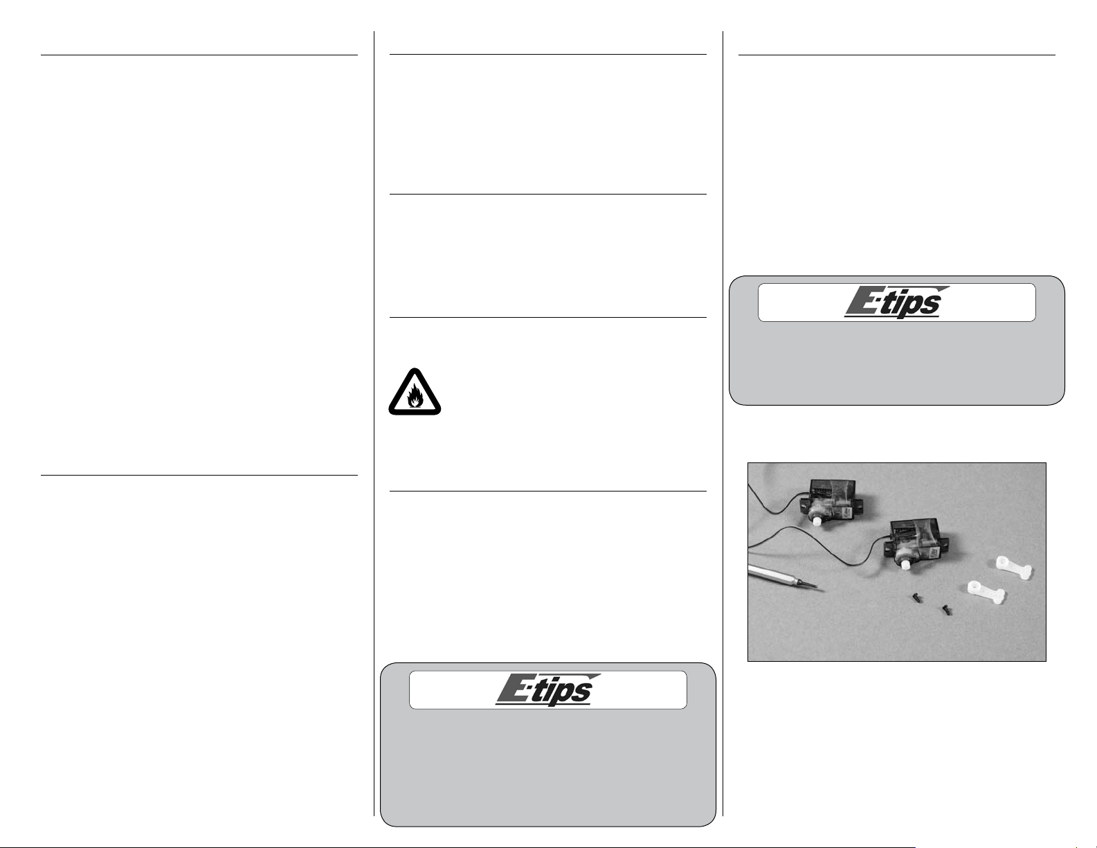
1. Use a #0 Phillips screwdriver to remove the
servo arms from the rudder and elevator servos.
3E-flite Nieuport 17 Slow Flyer Assembly Manual
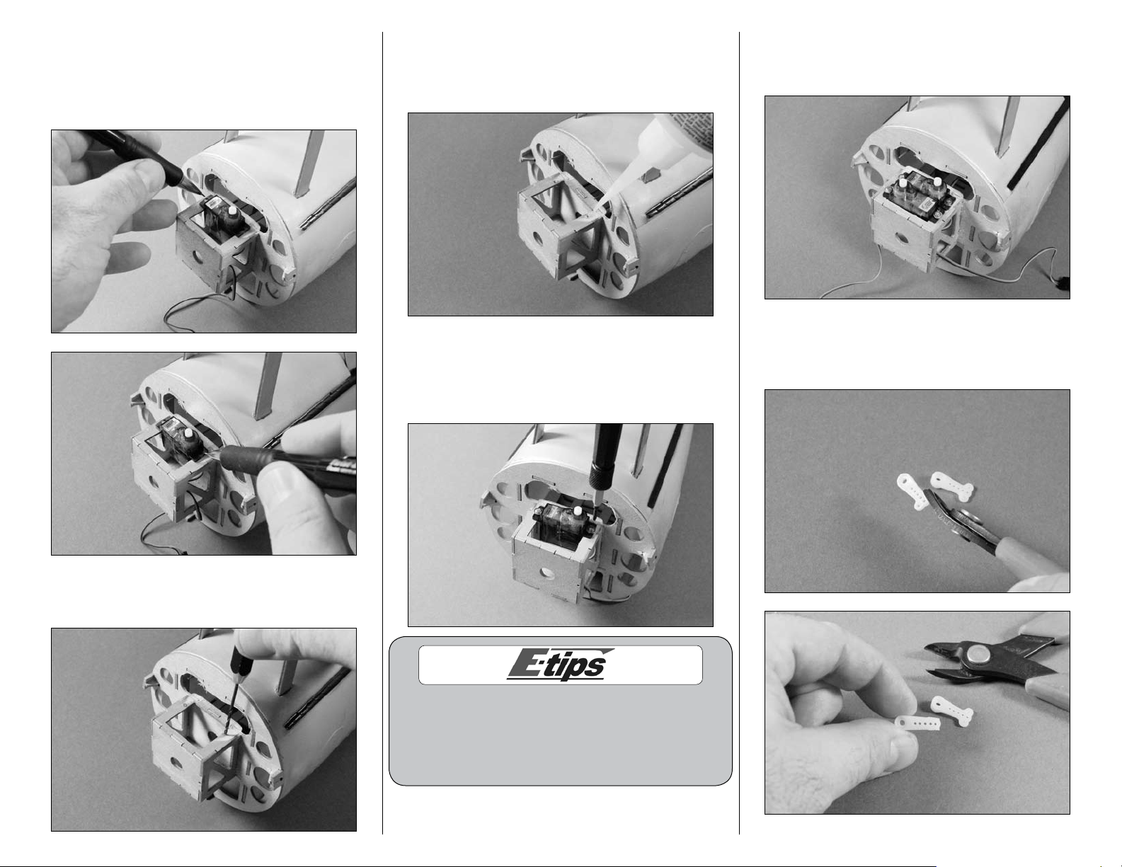
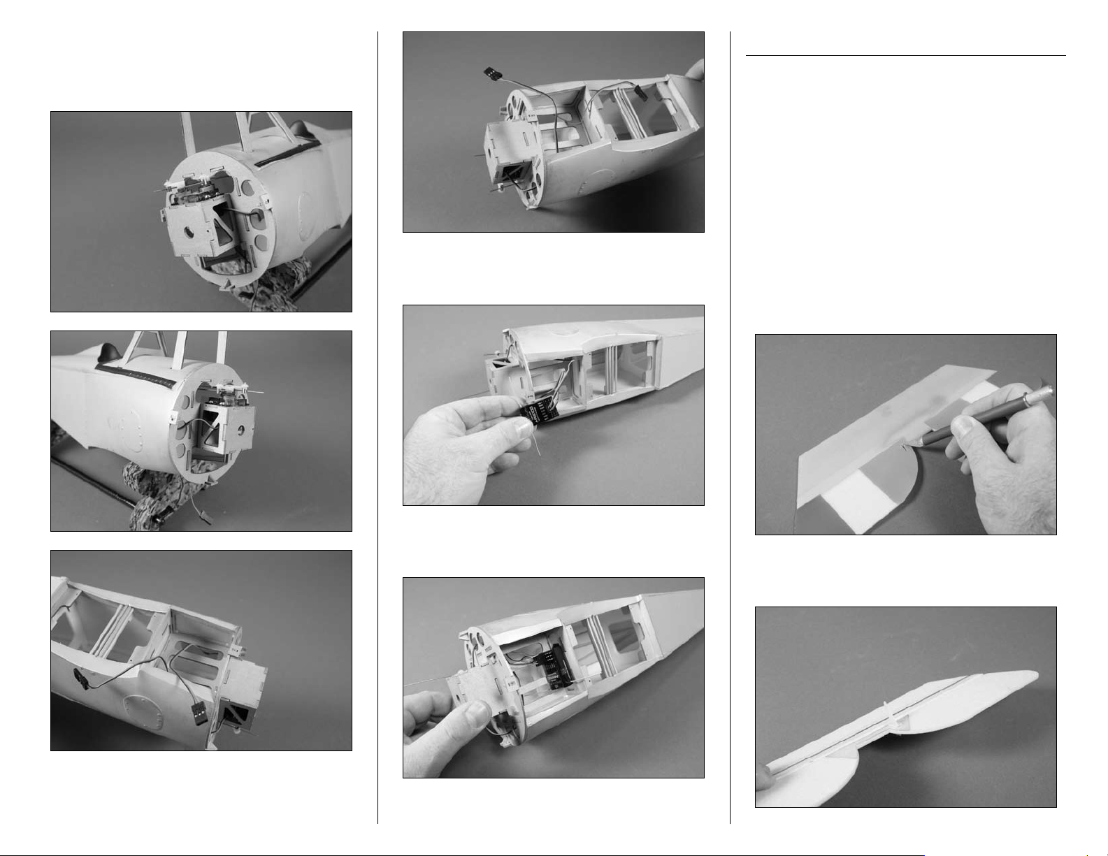
2. Position the rudder servo in the opening at the
front of the fuselage as shown. Slide the servo as
far back in the opening as possible. Use a pencil to
mark the position for the screws that will be used to
secure the rudder servo.
4. Apply 2–3 drops of thin CA into each of the
holes to harden the surrounding wood. This is done
to strengthen the wood and provide a stronger
surface for the servo mounting screws.
5. Position the rudder servo back in the opening
in the front of the fuselage. Use a #1 Phillips
screwdriver and the screws provided with the servo
to secure the rudder servo.
6. Repeat Steps 2 through 5 to install the elevator
servo. Note the direction of the output of the
elevator servo.
7. Use diagonal cutters to remove the ears of the
servo arm as shown. Use medium grit sandpaper
to smooth the servo arm for a finished look.
3. Use a pin drill and 1/16-inch (1.5mm) drill bit
to drill the holes for the two servo mounting screws.
It is best to support the fuselage with the palm of your
hand while installing the servo screws. The plywood
structure is strong enough for the model and flight
loads but could fail if extreme downward pressure is
placed on it during the servo mount screw installation.
4 E-flite Nieuport 17 Slow Flyer Assembly Manual
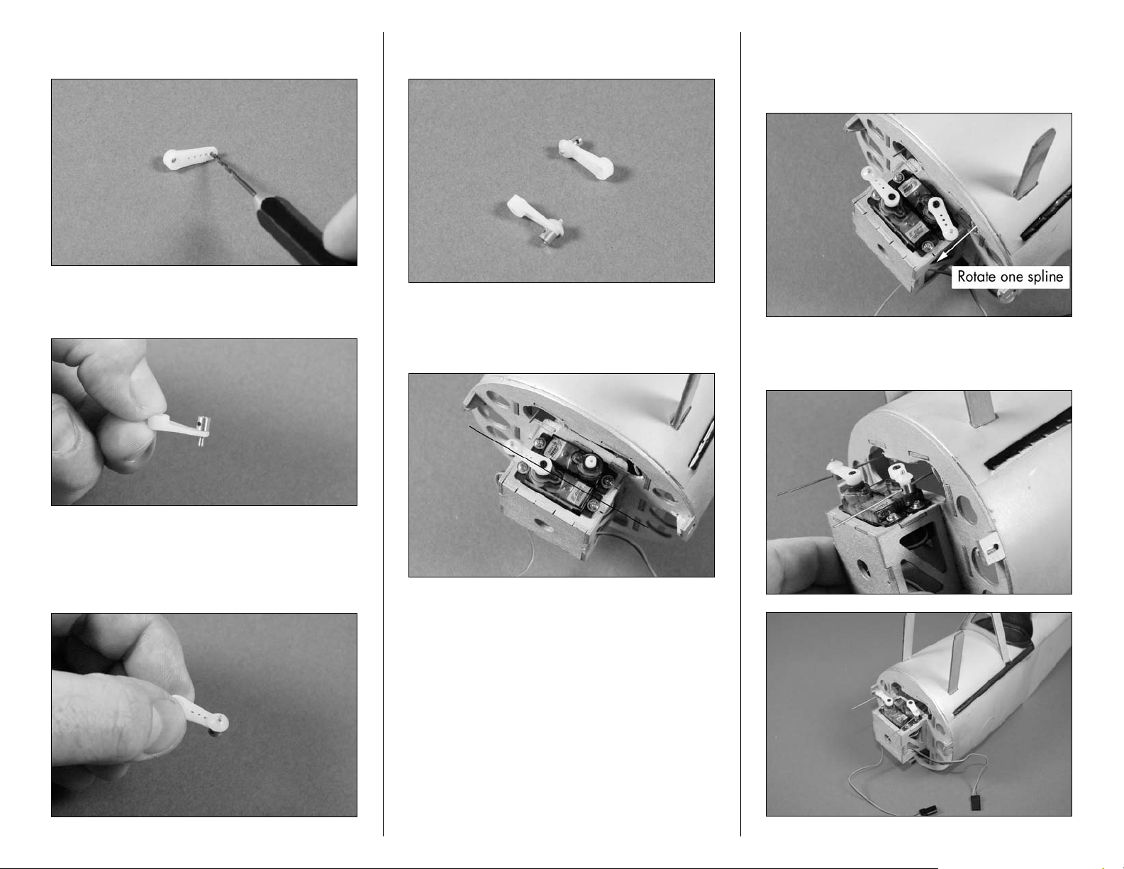
8. Use a pin drill and 1/16-inch (1.5mm) drill bit
to enlarge the outermost hole in the servo arm.
9. Insert the micro pushrod connector into the servo
arm from the bottom of the horn as shown.
11. Repeat Steps 7 through 10 so two servo arms
have been prepared for your servos.
12. Install the servo arm on the elevator servo. The
arm will be parallel to the center line of the servo
as shown.
13. Install the servo arm on the rudder servo. The
arm on the rudder servo is installed one spline off
from center so it will not interfere with the fuselage
during operation.
14. Slide the pushrod wires through the pushrod
connectors at this time.
10. Use a micro pushrod connector backplate to
secure the pushrod connector to the servo arm.
Use pliers to fully push the backplate tight on the
connector.
5E-flite Nieuport 17 Slow Flyer Assembly Manual
15. Pass the leads from the servos through the
center hole in the sub firewall and into the battery
compartment. Holes have been made inside the
fuselage for the servo leads to pass through.
16. Plug the rudder and elevator servo leads into
the appropriate ports of the receiver.
Stabilizer Installation
Required Parts
Fuselage Stabilizer/elevator
Micro control horn Micro control horn backplate
Required Tools and Adhesives
Foam-safe CA Hobby knife w/#11 blade
Felt-tipped pen Ruler
T-pins Pencil
1. Use a hobby knife with a #11 blade to remove
the hinge tape to fully expose the slot for the
elevator control horn. You may also need to
enlarge the plastic support piece slightly for the
control horn to fit. You want this slot to have a snug
fit, not a loose fit.
17. Use two-sided tape to secure the receiver in the
fuselage as shown.
6 E-flite Nieuport 17 Slow Flyer Assembly Manual
2. Slide the tab on the micro control horn through
the elevator from the bottom side as shown.
3. Slide the micro control horn backplate on the tab
Parallel
Work Surface
from the control horn. It will ratchet down and lock
into position. Slide the backplate so it holds the
control horn tightly in position.
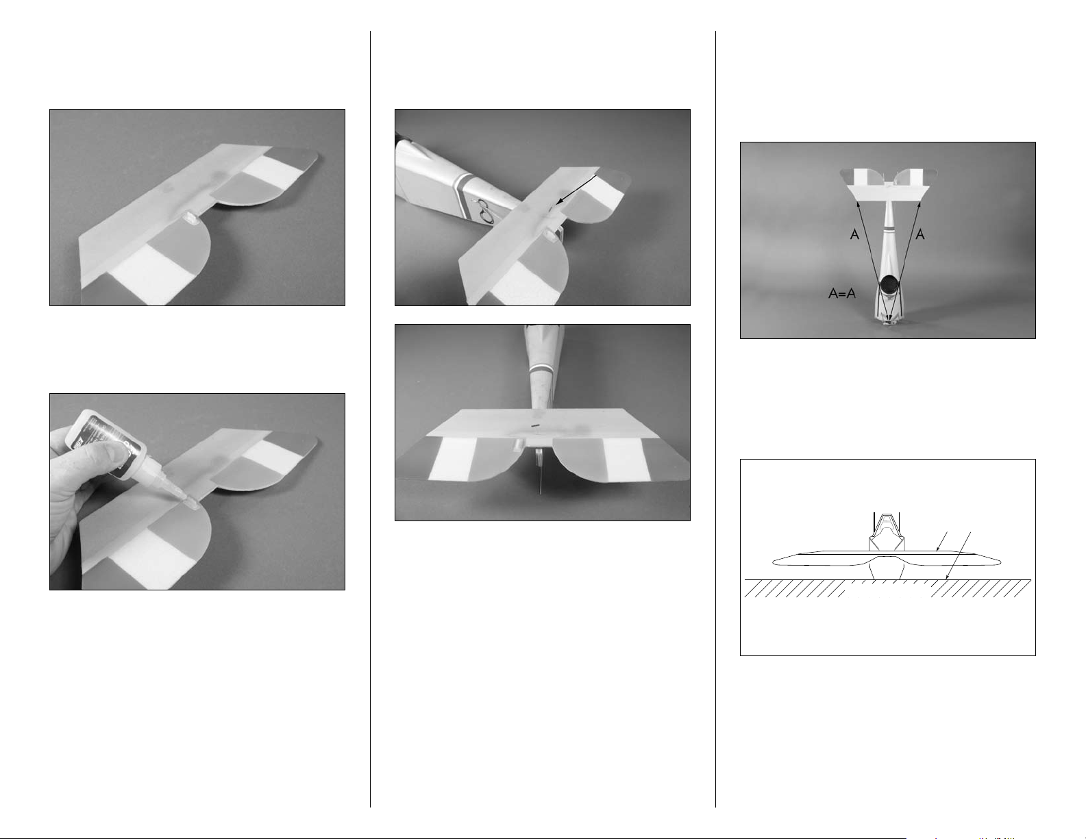
4. Apply 2–3 drops of foam-safe CA to the joint
between the backplate and control horn to keep it
secure for the life of your model.
5. Position the stabilizer on the fuselage as shown.
Make sure to center the stabilizer left-to-right on the
fuselage. Use a T-pin at the back of the stabilizer to
hold it in position for the following step.
6. Use a ruler to measure from a point center at
the front of the fuselage to each of the tips of the
stabilizer. The measurements must be equal for the
best performance from your model. Use a second
T-pin to keep the stabilizer in position for the
following step.
7. With the fuselage resting flat on your work
surface, check to verify the stabilizer is parallel
to the work surface. Lightly sand the area of the
fuselage where the stabilizer rests to correct any
alignment problems.
7E-flite Nieuport 17 Slow Flyer Assembly Manual

8. Use a pencil to trace the outline of the fuselage
on the bottom of the stabilizer. You will only need
to mark one side of the stabilizer in this step so you
can return the stabilizer to the correct alignment on
the fuselage.
Rudder Installation
Required Parts
Fuselage assembly CA hinge
Rudder
Micro control horn Micro control horn backplate
Required Tools and Adhesives
Felt-tipped pen Hobby scissors
Foam-safe CA Hobby knife w/#11 blade
Please follow the procedure as illustrated for
hinging the rudder. Trying to trim the hinge for
the control horn after it has been glued in the
rudder can cause damage to the rudder.
9. Remove the stabilizer from the fuselage. Apply
foam-safe CA to the fuselage where the stabilizer
fits. Using the line drawn on the bottom of the
stabilizer, reposition it on the fuselage. If the stab
saddle is flat you will still need to sand the paint off
this area before gluing the stab in place. Hold the
stabilizer tightly against the fuselage until the CA
fully cures.
1. Insert the CA hinge in the slot in the rudder.
8 E-flite Nieuport 17 Slow Flyer Assembly Manual
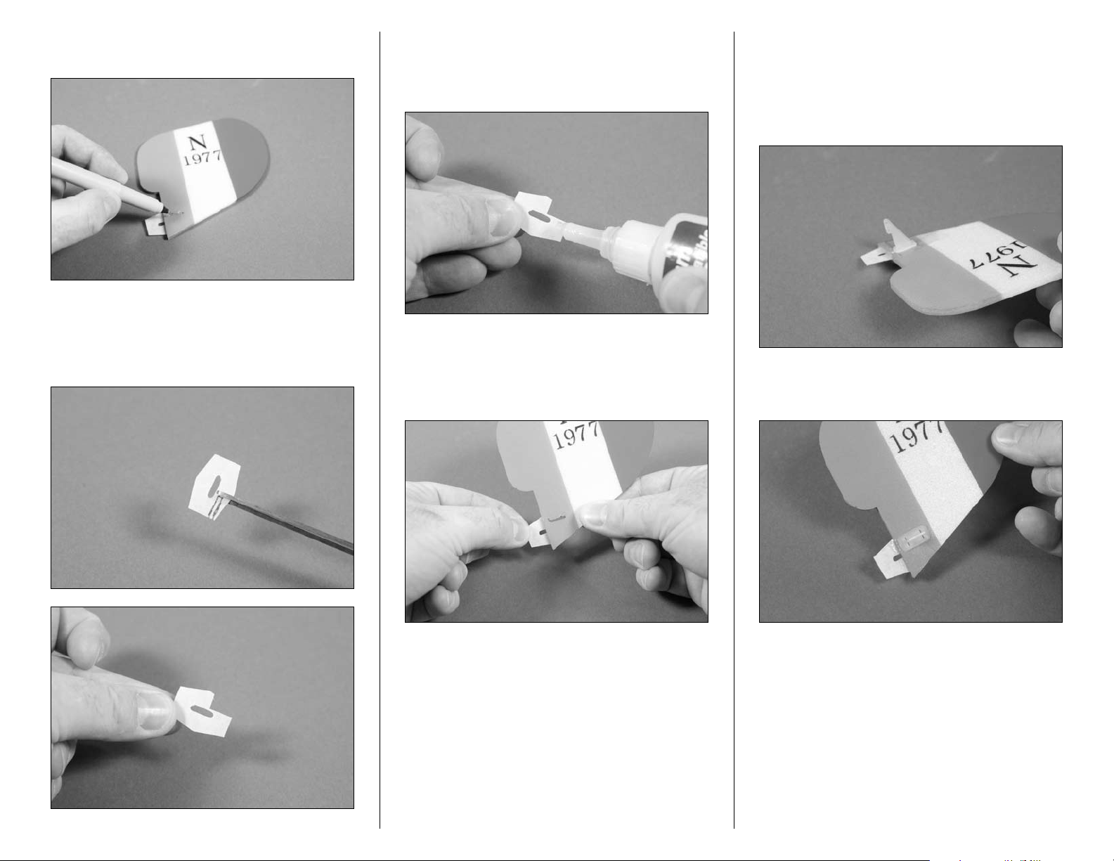
2. Use a felt-tipped pen to trace the outline of the
slot for the micro control horn onto the hinge.
3. Use scissors to notch the hinge based on
the position traced in the previous step. This is
necessary to provide clearance for the rudder
control horn.
4. Apply a small amount of foam-safe CA on the
side of the hinge that will be inserted in the rudder.
Make sure to apply CA to both sides of the hinge
to glue it securely in the rudder.
5. Insert the hinge half-way into the rudder. Allow
the CA to fully cure before proceeding. Do not use
CA accelerators as it will reduce the bond between
the hinge and rudder.
6. Insert the tab from the micro control horn
through the hole in the rudder. Note the side of
the rudder the control horn is installed in. You may
need to open the slot slightly with a hobby knife
and #11 blade. Ensure the control horn has a snug
fit, not a loose fit.
7. Use a micro control horn backplate to secure the
control horn in the rudder.
9E-flite Nieuport 17 Slow Flyer Assembly Manual
 Loading...