

Page 1
Mini Pulse XT
Assembly Manual
Page 2

Table of Contents
Introduction ................................................................3
Specifications .............................................................3
Using the Manual
Contents of Kit/Parts Layout
Required Radio Equipment
Important Information About Motor Selection
Sport Outrunner Setup
Optional Accessories
Required Tools and Adhesives
Note Regarding Hinges
Note on Lithium Polymer Batteries
Warning ....................................................................7
Limited Warranty Period
Limited Warranty & Limits of Liability
Safety Precautions
Questions, Assistance, and Repairs
Questions or Assistance
Inspection or Repairs
Warranty Inspection and Repairs
.......................................................3
.........................................4
...........................................5
.................6
.................................................6
..................................................6
......................................6
...............................................7
.................................7
..............................................8
.............................8
.......................................................9
...............................9
...............................................9
...................................................9
................................10
Non-Warranty Repairs ...............................................10
Safety, Precautions, and Warnings
Landing Gear Installation
Outrunner Motor Installation
Cowling Installation
Tail Installation
Wing Preparation
Final Assembly
Control Throws
Range Testing the Radio
Center of Gravity
Preflight ...................................................................32
Notes ......................................................................33
2006 Official AMA
National Model Aircraft Safety Code
..........................................................19
.........................................................26
.........................................................30
......................................................31
...........................................12
..................................................15
.....................................................24
............................................31
..............................11
.......................................14
..........................34
2
Page 3

Introduction
Using the Manual
Thank you for purchasing the Mini Pulse XT. Designed
from the beginning for electric power, the Mini Pulse XT
is developed from the Hangar 9® Pulse™ XT with the
same flight characteristics as the 40-size version. It is a
perfect transitional airplane for beginners who want to
learn aerobatics and for sport flyers who want an easy,
comfortable sport flyer. All flight control surfaces, hinges,
and control horns have been installed at the factory to
help speed up the building time.
Specifications
Wingspan: 42.5 in (1080mm)
Length: 37.5 in (875mm)
Wing Area: 330 sq in (21.5 sq dm)
Weight w/o Battery: 21–22 oz (710–820 g)
Weight w/ Battery: 25–27 oz (795–965 g)
This manual is divided into sections to help make assembly
easier to understand, and to provide breaks between each
major section. In addition, check boxes have been placed
next to each step to keep track of each step completed.
Steps with a single circle () are performed once, while
steps with two circles ( ) indicate that the step will
require repeating, such as for a right or left wing panel,
two servos, etc.
Remember to take your time and follow the directions.
3
Page 4

Contents of Kit/Parts Layout
Large Replacement Parts:
EFL2376 Wing w/Ailerons
EFL2377 Fuselage
EFL2378 Tail Set
EFL2380 Main Landing Gear
EFL2381 Cowling
EFL2382 Wheel Pants
Small Replacement Parts:
EFL2379 Pushrod Set
EFL2383 Motor X-Mount
EFLA200 Micro Control Horns
FLA203 Micro Control Connectors
EFLA219 Steerable Tailwheel Assembly
EFLA223 Foam Park Wheels, 2"
EFLA213 E-flite/JR/Horizon Decals
4
Page 5

Required Radio Equipment
You will need a minimum 4-channel transmitter, crystals,
micro receiver, and four sub-micro servos. You can choose
to purchase a complete radio system that includes all of
these items or, if you are using an existing transmitter, just
purchase the other required equipment separately.
Complete Radio System
SPM2460 DX6 DSM 6CH Park Flyer w/4-S75
Servos
Note: We recommend the crystal-free,
interference-free Spektrum® DX6 2.4GHz DSM®
6-Channel System, which includes a micro
receiver and 4 sub-micro servos.
Or Purchase Separately
SPM6000 AR6000 DSM DualLink™ 6-Channel
Park Flyer Rx
Or
JSP30610 6-Channel UltraLite Rx w/o Crystal,
Positive Shift JR/AIR (72MHz)
Or
JSP30615 6-Channel UltraLite Rx w/o Crystal,
Negative Shift FUT/HRC (72MHz)
JRPXFR** FM Receiver Crystal
JSP98110 6" Servo Extension (2)
JSP98030 12" Servo Extension (2)
JSP98020 Y-harness, Standard 6"
EFLRS75 7.5-Gram Sub-Micro Servo (4)
5
Page 6

Important Information About Motor
Selection
We recommend the E-flite® Park 450 Brushless Outrunner,
890Kv (EFLM1400) to provide you with excellent sport
and aerobatic power and a worry-free outrunner motor.
The Mini Pulse XT does not include a propeller, but we
recommend our 10X8 Electric Prop (EFLP1080E).
Sport Outrunner Setup
EFLM1400 Park 450 Brushless Outrunner
Motor, 890Kv
EFLA1025 25-Amp Pro Brushless ESC
THP21003SPL 2100mAh 3-Cell 11.1V Li-Po,
16GA
Or
EFLB1035 11.1V 2100mAh 3-Cell Li-Po,
16GA
EFLP1080E 10 x 8 Electric Prop
EFLAEC302 EC3 Battery Connector, Female (2)
EFLC3005 Celectra 1- to 3-cell Li-Po Charger
Optional Accessories
EFLA110 Power Meter
Required Tools and Adhesives
Tools & Equipment
EFLA250 Park Flyer Tool Assortment, 5-piece
Or Purchase Separately
EFLA257 Screwdriver, #0 Phillips (or included
with EFLA250)
EFLA251 Hex Wrench: 3/32" (or included
with EFLA250)
Nut driver: 1/4"
Drill
Drill bit: 1/16" (1.5mm), 5/64" (2mm)
Masking tape
Card stock
Felt-tipped pen
Needle-nose pliers
Canopy glue
This is a sport flyer setup for smooth and stable flights.
6
Page 7

Note Regarding Hinges
Note on Lithium Polymer Batteries
For your convenience and to speed the assembly process,
the hinges have already been installed and glued. We
suggest that you take a minute before beginning assembly
of your model to check them.
Grasp the wing and aileron at each hinge location, then
gently pull on the aileron to ensure the hinges are secure
and cannot easily be pulled away from either surface.
Use caution when gripping the wing and aileron to avoid
crushing or damaging the structure. Repeat this process for
the elevator and rudder.
If, however, you find that the hinges pull away, simply
wick thin CA into the hinge slots and reinstall the
hinges/surfaces.
Lithium Polymer batteries are significantly
more volatile than alkaline or Ni-Cd/Ni-MH
batteries used in RC applications. All
manufacturer’s instructions and warnings
must be followed closely. Mishandling of
Li-Po batteries can result in fire. Always follow
the manufacturer’s instructions when disposing
of Lithium Polymer batteries.
Warning
An RC aircraft is not a toy! If misused, it can cause
serious bodily harm and damage to property. Fly
only in open areas, preferably at AMA (Academy of
Model Aeronautics) approved flying sites, following all
instructions included with your radio.
Keep loose items that can get entangled in the propeller
away from the prop, including loose clothing, or other
objects such as pencils and screwdrivers. Especially keep
your hands away from the propeller.
7
Page 8

Limited Warranty Period
Horizon Hobby, Inc. guarantees this product to be free
from defects in both material and workmanship at the
date of purchase.
Limited Warranty & Limits of Liability
Pursuant to this Limited Warranty, Horizon Hobby, Inc.
will, at its option, (i) repair or (ii) replace, any product
determined by Horizon Hobby, Inc. to be defective. In the
event of a defect, these are your exclusive remedies.
This warranty does not cover cosmetic damage or damage
due to acts of God, accident, misuse, abuse, negligence,
commercial use, or modification of or to any part of
the product. This warranty does not cover damage due
to improper installation, operation, maintenance, or
attempted repair by anyone other than an authorized
Horizon Hobby, Inc. service center. This warranty is
limited to the original purchaser and is not transferable.
In no case shall Horizon Hobby’s liability exceed the
original cost of the purchased product and will not
cover consequential, incidental or collateral damage.
Horizon Hobby, Inc. reserves the right to inspect any and
all equipment involved in a warranty claim. Repair or
replacement decisions are at the sole discretion of Horizon
Hobby, Inc. Further, Horizon Hobby reserves the right to
change or modify this warranty without notice.
REPAIR OR REPLACEMENT AS PROVIDED UNDER
THIS WARRANTY IS THE EXCLUSIVE REMEDY OF
THE CONSUMER. HORIZON HOBBY, INC. SHALL
NOT BE LIABLE FOR ANY INCIDENTAL OR
CONSEQUENTIAL DAMAGES.
As Horizon Hobby, Inc. has no control over use, setup,
final assembly, modification or misuse, no liability shall be
assumed nor accepted for any resulting damage or injury.
By the act of use, setup or assembly, the user accepts all
resulting liability.
If you as the purchaser or user are not prepared to accept
the liability associated with the use of this product, you
are advised to return this product immediately in new and
unused condition to the place of purchase.
8
Page 9

Safety Precautions
Questions or Assistance
This is a sophisticated hobby product and not a toy. It
must be operated with caution and common sense and
requires some basic mechanical ability. Failure to operate
this product in a safe and responsible manner could result
in injury or damage to the product or other property. This
product is not intended for use by children without direct
adult supervision.
The product manual contains instructions for safety,
operation and maintenance. It is essential to read and
follow all the instructions and warnings in the manual,
prior to assembly, setup or use, in order to operate
correctly and avoid damage or injury.
Questions, Assistance, and Repairs
Your local hobby store and/or place of purchase cannot
provide warranty support or repair. Once assembly, setup
or use of the product has been started, you must contact
Horizon Hobby, Inc. directly. This will enable Horizon to
better answer your questions and service you in the event
that you may need any assistance.
For questions or assistance, please direct your email to
productsupport@horizonhobby.com, or call 877.504.0233
toll-free to speak to a service technician.
Inspection or Repairs
If your product needs to be inspected or repaired, please
call for a Return Merchandise Authorization (RMA). Pack
the product securely using a shipping carton. Please note
that original boxes may be included, but are not designed
to withstand the rigors of shipping without additional
protection. Ship via a carrier that provides tracking and
insurance for lost or damaged parcels, as Horizon Hobby,
Inc. is not responsible for merchandise until it arrives and
is accepted at our facility. Include your complete name,
address, phone number where you can be reached during
business days, RMA number, and a brief summary of the
problem. Be sure your name, address, and RMA number
are clearly written on the shipping carton.
9
Page 10

Warranty Inspection and Repairs
Non-Warranty Repairs
To receive warranty service, you must include your
original sales receipt verifying the proof-of-purchase
date. Providing warranty conditions have been met, your
product will be repaired or replaced free of charge.
Repair or replacement decisions are at the sole discretion
of Horizon Hobby.
Should your repair not be covered by warranty and the
expense exceeds 50% of the retail purchase cost, you will
be provided with an estimate advising you of your options.
You will be billed for any return freight for non-warranty
repairs. Please advise us of your preferred method of
payment. Horizon Hobby accepts money orders and
cashiers checks, as well as Visa, MasterCard, American
Express, and Discover cards. If you choose to pay by
credit card, please include your credit card number and
expiration date. Any repair left unpaid or unclaimed
after 90 days will be considered abandoned and will be
disposed of accordingly.
Electronics and engines requiring inspection or
repair should be shipped to the following address
(freight prepaid):
Horizon Service Center
4105 Fieldstone Road
Champaign, Illinois 61822
All other products requiring inspection or repair should be
shipped to the following address (freight prepaid):
Horizon Product Support
4105 Fieldstone Road
Champaign, Illinois 61822
10
Page 11

Safety, Precautions, and Warnings
As the user of this product, you are solely responsible for
operating it in a manner that does not endanger yourself
and others or result in damage to the product or the
property of others.
Carefully follow the directions and warnings for this and
any optional support equipment (chargers, rechargeable
battery packs, etc.) that you use.
This model is controlled by a radio signal that is subject to
interference from many sources outside your control. This
interference can cause momentary loss of control so it is
necessary to always keep a safe distance in all directions
around your model, as this margin will help to avoid
collisions or injury.
• Always operate your model in an open area away from
cars, traffic, or people.
• Avoid operating your model in the street where injury or
damage can occur.
• Never operate the model out into the street or populated
areas for any reason.
• Never operate your model with low transmitter batteries.
• Carefully follow the directions and warnings for this and
any optional support equipment (chargers, rechargeable
battery packs, etc.) that you use.
• Keep all chemicals, small parts and anything electrical
out of the reach of children.
• Moisture causes damage to electronics. Avoid water
exposure to all equipment not specifically designed and
protected for this purpose.
11
Page 12

Landing Gear Installation
Required Parts
Fuselage
Main landing gear
Wheel pant (L&R)
2" (50mm) wheel (2)
4-40 x 1/2" socket head bolts (2)
#4 black washers (2)
4-40 nut (2)
4-40 locknut (2)
4-40 x 1
#4 steel washers (4)
2mm x 6mm wood screws (2)
Required Tools and Adhesives
Hex wrench: 3/32"
Phillips screwdriver (small)
Nut driver: 1/4"
Needle-nose pliers
1
/
" socket head bolts (2)
4
Note: You may consider using a larger
diameter wheel, such as 2
1
/
" (58mm), if
4
your flying site has rough terrain. By using a
larger wheel, you will not be able to use the
included wheel pants.
1. Place the landing gear onto the bottom of
the fuselage. They will angle back slightly when
installed in the correct direction. Attach with
two 4-40 x 1/2" socket head bolts and two #4
black washers.
12
Page 13

2. Slide the 4-40 x 1
1
/
" socket head bolt
4
through one of the 2" wheels. Slide a #4 steel
washer so it fits against the wheel. Next secure
a 4-40 nut against the washer. Make sure the
wheel still spins freely. Slide a second #4 steel
washer onto the bolt. This washer will fit inside
the wheel pant.
3. Fit the assembly in Step 2 into the wheel pant
and insert the bolt into the landing gear. With
the fuselage level to the work surface, rotate the
wheel pant so it is also level to your work surface
and secure the pant to the landing gear with a
2mm x 6mm wood screw. Secure the bolt with
a 4-40 locknut while using needle-nose pliers to
hold the head of the bolt inside the pant.
3. Repeat Steps 2 and 3 for the remaining wheel
and wheel pant.
13
Page 14

Outrunner Motor Installation
Required Parts
Fuselage
Brushless motor
4-40 x 1
Aluminum motor spacer, 13/16" (20mm) (4)
Required Tools and Adhesives
Hex wrench: 3/32"
Screwdriver (Phillips #0)
1
/
" socket head screw (4)
4
Note: This section covers the installation of
the recommended Park 450 Outrunner motor.
The holes in the firewall for mounting the
custom X-mount will also fit the hole pattern for
our E-flite® Firewall Stick Mount (EFLM1916
– available separately) if you prefer to use a
gearbox with an inrunner motor.
1. Attach the supplied aluminum motor X-mount
to the motor using the screws provided with the
motor. The wider section of the mount will be
positioned towards the motor wires.
14
Page 15

2. Attach the Outrunner motor to the front of the
firewall using four 4-40 x 1
screws and the aluminum motor spacers.
1
/
" socket head
4
Cowling Installation
Required Parts
Fuselage w/motor installed
Cowling
2mm x 8mm wood screw (4)
Propeller
Spinner
Prop adapter (for outrunner motor)
Electronic speed control
Required Tools and Adhesives
Screwdriver (Phillips #0)
Cardstock
Masking tape
Drill
Drill bit; 1/16" (1.5mm), 5/64" (2mm)
Important Information About Your Brushless ESC
Make sure your ESC brake is programmed to Off.
Also, be sure to use an ESC with the proper 9V cutoff
when using 3-cell Li-Po packs, or 6V cutoff when using
2-cell Li-Po packs.
15
Page 16

Important Information About Your Propeller
It is also very important to check to be sure the
propeller is balanced before installing onto the shaft. An
unbalanced propeller may strip the gears or cause poor
flight characteristics.
1. Solder any connectors to the speed control
to connect to the motor battery and motor if
necessary. Connect the ESC to the motor and
secure it to the inside of the fuselage using hook
and loop material. Actual ESC location may vary.
16
Page 17

2. Connect the speed control to the radio system
and motor battery. Check that the motor is
rotating in the correct direction. It will rotate
counterclockwise when viewed from the front of
the aircraft. Use the instructions with your speed
control to correct a motor that is operating in the
wrong direction.
3. Tape small pieces of cardstock to the fuselage to
indicate the locations of the cowl mounting tabs
at the front of the fuselage.
4. Slide the cowling onto the fuselage. Install the
propeller adapter onto the Outrunner shaft. You
may need to ream out the hole on your prop hub
to fit the prop adapter shaft at this point. Slide the
propeller onto the prop adapter shaft. The spinner
backplate and spacers may need to be enlarged
as well to fit the prop adapter. Slide the spinner
backplate and any needed spacers onto the prop
adapter shaft. Secure the propeller using the prop
adapter spinner and be sure it is secure and tight.
17
Page 18
Note: Make sure to check the balance of
the propeller after enlarging the hole in the
propeller.
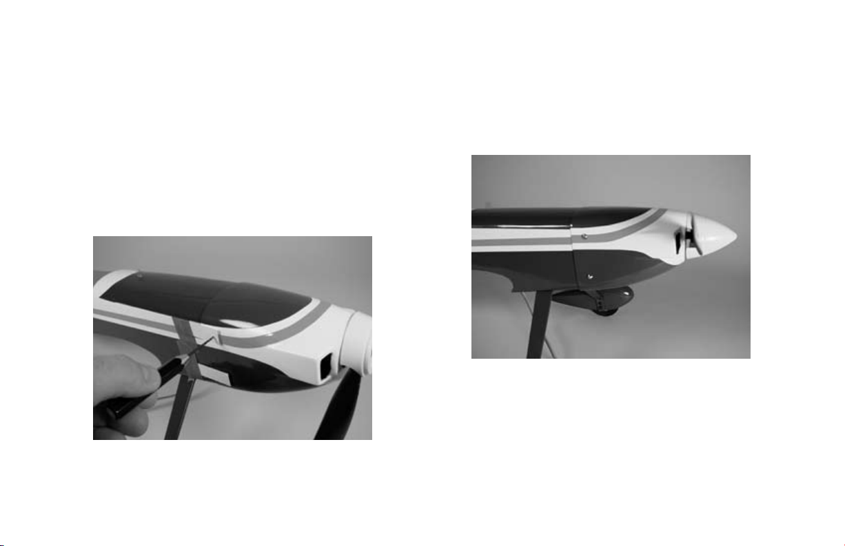
5. Position the cowl so it is around 1/16"–1/8"
(1.5mm–3mm) from the spinner backplate. Use
the cardstock to drill four 1/16" (1.5mm) holes
through the cowl into the cowl mounting tabs in
the fuselage.
6. Enlarge the holes in the cowl using a 5/64"
(2mm) drill bit. Secure the cowl using four
2mm x 8mm sheet metal screws. Snap the
spinner cone onto the spinner backplate once
the cowl is secure.
Hint: Use thin CA to harden the holes drilled
into the cowl mounting tabs. This will help to
prevent the screws from vibrating loose in flight.
18
Page 19

Tail Installation
Required Parts
Fuselage
Rudder/Fin
Stabilizer/Elevator
Servo (2)
Servo extension, 12" (305mm) (2)
Control connectors w/backplate (2)
2mm x 4mm screw (2)
4-40 locknut (2)
#4 washer (2)
Linkage wire, 4" (102mm) for elevator
Linkage wire, 5
Tailwheel, 3/4"
Wheel collar (tailwheel)
Required Tools and Adhesives
Nut driver: 1/4"
Drill
Drill bit: 1/16" (1.5mm)
Screwdriver, #0 Phillips
1
/
" (140mm) for rudder
2
1. Attach the tail wheel to the tail gear wire using a
1/16" wheel collar and setscrew.
19
Page 20

2. Locate the stabilizer/elevator assembly. Position
the stabilizer/elevator assembly so the control
horn will face down, away from the fin. The
threaded rods from the rudder/fin assembly will
slide into the two holes in the stabilizer.
3. Slide the rudder/stabilizer assembly onto the
fuselage. Slide the #4 washers onto the threaded
rods. Thread the nuts onto the rod, tightening
them snugly against the bottom of the fuselage.
Note: The tail section is removable for easy
transporting if needed.
20
Page 21

4. Attach a 12" (305mm) servo extension to
a servo lead. Use thread or a commercially
available connector to secure the extension to
the servo lead.
5. Install the elevator servo into the fuselage
using the hardware provided with the servo.
Drill 1/16" (1.5mm) holes into the fuselage
for the screws.
21
Page 22

6. Remove the servo arm from the elevator
servo. Drill a 1/16" (1.5mm) hole through
the center hole in the arm. Slide the control
connector through the hole and secure it using
the connector backplate.
7. Repeat Steps 4 through 6 for the rudder servo.
22
Page 23

8. Locate the 4" (102mm) linkage wire. Slide the
“Z” bend into the center hole of the elevator
control horn. Pass the linkage through the
pushrod connector on the servo arm. Turn on
the radio and plug the elevator servo into the
receiver. Center the elevator trim and stick, and
check that the sub-trim (if a programmable radio)
has been set to 0. Install the servo horn back onto
the elevator servo. Use a 2mm x 4mm screw to
secure the linkage.
9. Repeat Step 7 for the rudder linkage.
23
Page 24

Wing Preparation
Required Parts
Wing
6-channel receiver
Servo w/hardware (2)
Servo extension, 6" (152mm)
Y-harness, standard 6" (2)
Control connectors w/backplate (2)
2mm x 4mm screw (2)
1
4
/
" (118mm) pushrod wire (2)
4
Required Tools and Adhesives
Drill
Drill bit: 1/16" (1.5mm)
Screwdriver, #0 Phillips
1. Secure a 6" (152mm) servo extension onto
the servo lead. Install the aileron servo into the
wing, using the pre-installed string to pull the
servo lead through the wing. The servo lead will
exit the hole in the top center of the wing. Drill
a 1/16” (1.5mm) hole through the tabs on the
servo into the servo mount. Be careful not to
drill through the covering in the top of the wing.
Secure the servo using the hardware that was
provided with the servo.
24
Page 25

2. Drill a 1/16" (1.5mm) hole in the servo arm
for the pushrod connector. Secure the control
connector in the servo arm using the connector
backplate.
3. Locate the 4
“Z” bend into the center hole of the aileron
control horn. Pass the linkage through the
control connector.
1
/
" (118mm) linkage. Place the
4
4. Plug the aileron servo into the receiver. Power
up the transmitter and receiver. Center the aileron
stick, trim, and any programmed sub-trim values.
Install the arm on the servo so it is parallel to the
aileron hinge line. Use a 2mm x 4mm screw to
secure the linkage.
5. Repeat Steps 1 through 4 for the remaining
aileron servo. Then connect a 6" Y-harness to the
two 6" servo extensions on the servos.
25
Page 26
Final Assembly
Required Parts
Fuselage
Wing
Canopy
Receiver
Battery
Battery hatch
4-40 x 1" socket head bolt (2)
#4 washer (2)
Hook and loop tape
Hook and loop strap
Required Tools and Adhesives
Hex wrench: 3/32"
Felt-tipped pen
Canopy glue
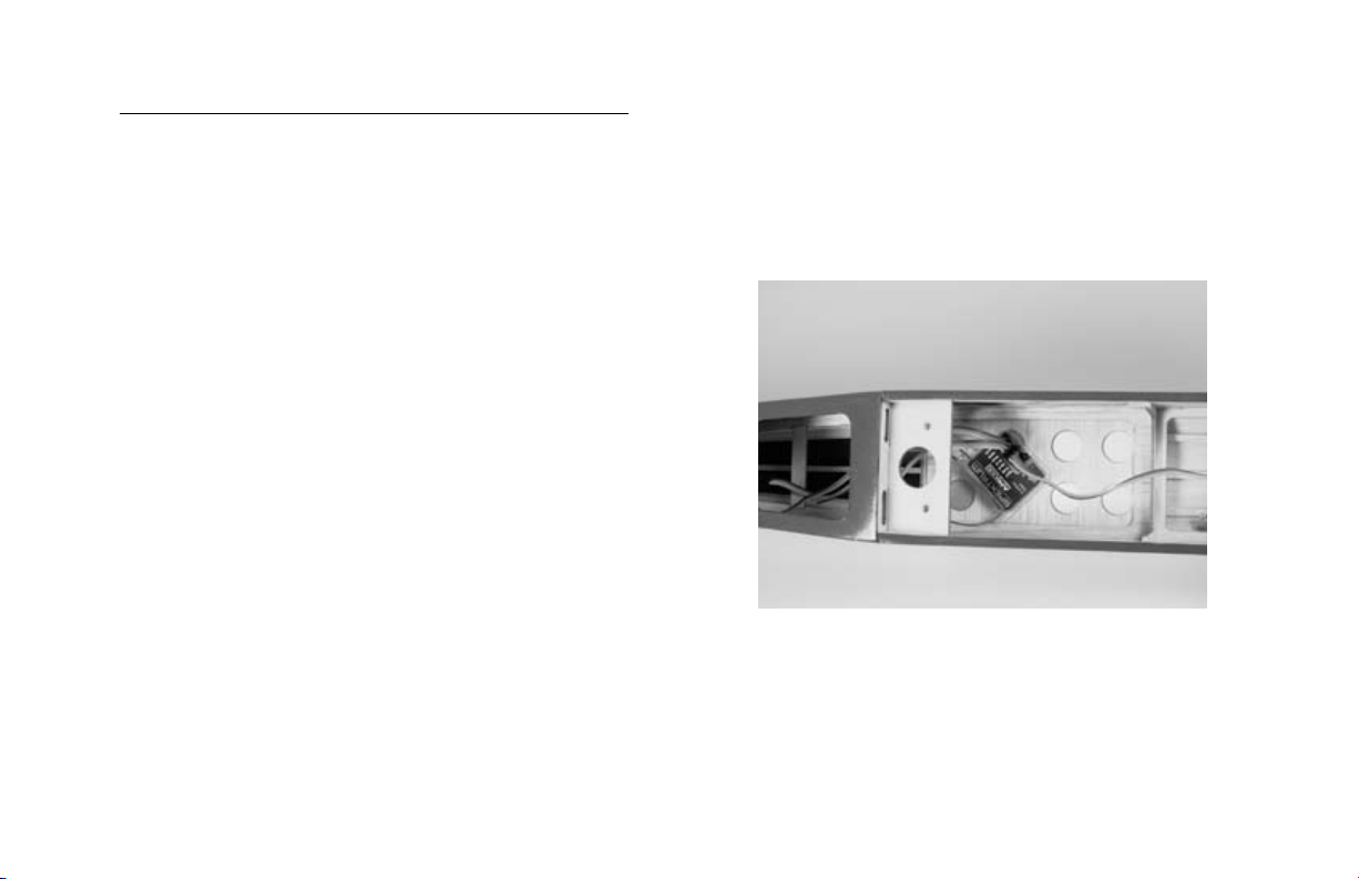
1. Plug in the elevator and rudder servos and ESC
into the receiver. Mount the receiver to the inside
of the fuselage using hook and loop material.
Route the antenna wire through the bottom of the
fuselage to the rear, or as directed by your radio
instruction manual.
Note: Do not cut or change the length of the
antenna wire, as this will reduce the range of
your radio system.
26
Page 27

2. Place the canopy into position on the fuselage.
Use a felt-tipped pen to trace the outline of the
canopy onto the fuselage.
3. Use medium grit sandpaper to roughen the
covering 1/8" (3mm) inside the line drawn. Also
roughen the outside 1/8" (3mm) of the canopy.
Clean the sanded areas using a paper towel and
rubbing alcohol.
27
Page 28

4. Use Formula 560 canopy glue to glue the canopy
to the fuselage. Use masking tape to hold the
canopy in position until the glue fully cures.
5. Plug the Y-harness for the aileron servos into
the receiver. Attach the wing to the fuselage
using two 4-40 x 1" socket head screws and
two #4 washers.
28
Page 29

6. With the aircraft fully assembled, install the
battery into the battery compartment. Secure the
battery using the hook and loop tape and a hook
and loop strap.
Note: Place a piece of hook and loop tape on
the bottom of the battery and on the fuselage
where the battery rests. This will keep the
battery from shifting forward or backward
during extreme maneuvers.
7. Install the battery hatch to the top of the fuselage.
The magnet will hold the battery hatch in place.
29
Page 30

Control Throws
1. Turn on the transmitter and receiver of your Mini
Pulse XT. Check the movement of the rudder,
elevator and ailerons using the transmitter.
Reverse the direction of the servos at the
transmitter if necessary.
2. Use a ruler to adjust the throw of the elevator,
ailerons and rudder. Adjust the position of
the pushrod at the control horn to achieve the
following measurements when moving the sticks to
their endpoints.
Measurements are taken at the widest point on the surface.
Low Rate High Rate
Ailerons:
Up/Down 3/8" (9mm) 1/2" (13mm)
Elevator:
Up/Down 1/4" (6mm) 1/2" (13mm)
Rudder:
Right/Left 1
1
/
" (32mm) 1
4
1
/
" (38mm)
2
These are general guidelines measured from our own flight
tests. You can experiment with higher rates to match your
preferred style of flying.
30
Page 31

Range Testing the Radio
1. Be sure to range check your radio before each
flying session. This is accomplished by turning
on your transmitter with the antenna collapsed.
Turn on the receiver in your airplane. With
your airplane on the ground and the engine
running, you should be able to walk 30 paces
(approximately 100 feet) away from your
airplane and still have complete control of all
functions. If not, don’t attempt to fly! Have your
radio equipment checked out by the manufacturer.
2. Double-check that all controls (aileron, elevator,
rudder and throttle) move in the correct direction.
3. Be sure that your transmitter batteries are
fully charged, per the instructions included
with your radio.
Center of Gravity
Caution: Do not inadvertently skip this step!
The recommended Center of Gravity (CG) location for the
Mini Pulse XT is 2
the upper wing against the fuselage. After the first flights,
the throws can be adjusted for your personal preference.
3
/
" (70mm) behind the leading edge of
4
31
Page 32

Preflight
Check Your Radio
Before going to the field, be sure that your batteries are
fully charged per the instructions included with your radio.
Charge both the transmitter and receiver pack for your
airplane. Use the recommended charger supplied with
your particular radio system, following the instructions
provided with the radio. In most cases, the radio should be
charged the night before going out flying.
Before each flying session, be sure to range check
your radio. See your radio manual for the recommended
range and instructions for your radio system. Each
radio manufacturer specifies different procedures for their
radio systems. Next, start the motor. With the
model securely anchored, check the range again. The
range test should not be significantly affected. If it is,
don’t attempt to fly! Have your radio equipment
checked out by the manufacturer.
Note: Keep loose items that can get entangled
in the propeller away from the prop. These
include loose clothing, or other objects such as
pencils and screwdrivers. Especially keep your
hands away from the propeller.
Double-check that all controls (aileron, elevator, rudder
and throttle) move in the correct direction.
Check the radio installation and make sure all the
control surfaces are moving correctly (i.e. the correct
direction and with the recommended throws). Test run
the motor and make sure it transitions smoothly from
off to full throttle and back. Also ensure the engine is
installed according to the manufacturer’s instructions,
and it will operate consistently.
Check all the control horns, servo horns, and clevises to
make sure they are secure and in good condition. Replace
any items that would be considered questionable. Failure
of any of these components in flight would mean the loss
of your aircraft.
32
Page 33

Notes
33
Page 34

2006 Official AMA National Model Aircraft Safety Code
GENERAL
1) I will not fly my model aircraft in sanctioned events,
air shows or model flying demonstrations until it has
been proven to be airworthy by having been previously,
successfully flight tested.
2) I will not fly my model higher than approximately 400
feet within 3 miles of an airport without notifying the
airport operator. I will give right-of-way and avoid flying
in the proximity of full-scale aircraft. Where necessary,
an observer shall be utilized to supervise flying to avoid
having models fly in the proximity of full-scale aircraft.
3) Where established, I will abide by the safety rules for
the flying site I use, and I will not willfully or deliberately
fly my models in a careless, reckless and/or dangerous
manner.
4) The maximum takeoff weight of a model is 55 pounds,
except models flown under Experimental Aircraft rules.
5) I will not fly my model unless it is identified with my
name and address or AMA number on or in the model.
(This does not apply to models while being flown indoors.)
6) I will not operate models with metal-bladed propellers
or with gaseous boosts, in which gases other than air
enter their internal combustion engine(s); nor will I operate
models with extremely hazardous fuels such as those
containing tetranitromethane or hydrazine.
RADIO CONTROL
1) I will have completed a successful radio equipment
ground range check before the first flight of a new or
repaired model.
2) I will not fly my model aircraft in the presence of
spectators until I become a qualified flier, unless assisted
by an experienced helper.
3) At all flying sites a straight or curved line(s) must be
established in front of which all flying takes place with the
other side for spectators. Only personnel involved with
flying the aircraft are allowed at or in front of the flight
line. Intentional flying behind the flight line is prohibited.
34
Page 35

2006 Official AMA National Model Aircraft Safety Code
4) I will operate my model using only radio control
frequencies currently allowed by the Federal
Communications Commission. (Only properly licensed
Amateurs are authorized to operate equipment on
Amateur Band frequencies.)
5) Flying sites separated by three miles or more are
considered safe from site-to-site interference, even when
both sites use the same frequencies. Any circumstances
under three miles separation require a frequency
management arrangement, which may be either an
allocation of specific frequencies for each site or testing to
determine that freedom from interference exists. Allocation
plans or interference test reports shall be signed by the
parties involved and provided to AMA Headquarters.
Documents of agreement and reports may exist between
(1) two or more AMA Chartered Clubs, (2) AMA clubs
and individual AMA members not associated with AMA
Clubs, or (3) two or more individual AMA members.
6) For Combat, distance between combat engagement
line and spectator line will be 500 feet per cubic inch of
engine displacement. (Example: .40 engine = 200 feet.);
electric motors will be based on equivalent combustion
engine size. Additional safety requirements will be per the
RC Combat section of the current Competition Regulations.
7) At air shows or model flying demonstrations, a single
straight line must be established, one side of which is for
flying, with the other side for spectators.
8) With the exception of events flown under AMA
Competition rules, after launch, except for pilots or helpers
being used, no powered model may be flown closer than
25 feet to any person.
9) Under no circumstances may a pilot or other person
touch a powered model in flight.
35
Page 36

9249
®
© 2006 Horizon Hobby, Inc.
4105 Fieldstone Road
Champaign, Illinois 61822
(877) 504-0233
horizonhobby.com
E-fliteRC.com
 Loading...