

Page 1
F-86 Sabre 15 DF
Assembly Manual
Pilot not included (PKZ7003)
Specifications
Wingspan: 33.8 in (860mm)
Length: 35.4 in (900mm)
Wing Area: 256 sq in (16.5 sq dm)
Weight w/o Battery: 40–42 oz (1135–1190 g)
Weight w/Battery: 53–55 oz (1500–1560 g)
Page 2

Table of Contents
Introduction
Contents of Kit/Parts Layout
Introduction ........................................................... 2
Important Information Regarding
Warranty Information ........................................ 2
Using the Manual ................................................... 2
Contents of Kit/Parts Layout .................................... 2
Recommended Radio Equipment ............................. 3
Required Brushless Ducted Fan Setup ....................... 3
Required Tools and Adhesives ................................. 3
Optional Accessories .............................................. 3
Warnings .............................................................. 3
Aileron Servo Installation ........................................ 4
Aileron Linkage Installation ..................................... 6
Mounting the Main Wing Panels ............................. 9
Stabilizer Installation ............................................ 12
Elevator Installation .............................................. 15
Rudder Installation ............................................... 16
Elevator Servo and Linkage Installation .................. 18
Rudder Servo and Linkage Installation ................... 22
Landing Gear Installation ...................................... 24
Steering Servo and Linkage Installation .................. 26
Speed Control and Receiver Installation ................. 27
Intake Tube Installation.......................................... 29
Fan Installation..................................................... 30
Exhaust Tube Installation ....................................... 32
Securing the Intake Tube ....................................... 34
Canopy Assembly ................................................ 35
Motor Battery Installation ...................................... 35
Decal Placement ................................................... 36
Center of Gravity ................................................. 36
Control Throws..................................................... 37
Preflight ............................................................... 38
Flying Your F-86 Sabre 15 DF............................... 38
Range Test Your Radio .......................................... 38
Safety Do’s and Don’ts for Pilots ............................ 39
Daily Flight Checks ............................................... 39
Warranty and Repair Policy .................................. 39
Warranty Services ................................................ 40
Compliance Information for the European Union .... 41
2010 Official Academy of
Model Aeronautics Safety Code ....................... 41
This performance model was designed around E-flite’s
Delta-V 15 (69mm) fan unit and matched 15 DF
3200Kv brushless motor. Pilots can use a 4-cell Li-Po
battery pack for great performance. The built-in fan
mounts make installing the fan easy—just drop in
the fan unit and tighten four screws. The removable
magnetic front hatch also allows easy access to the
radio equipment and battery. The entire trim scheme
is prepainted, pre-trimmed; the wings are covered in
UltraCote®. Just add your favorite nose art decals and
enjoy.
Important Information
Regarding Warranty Information
Please read our Warranty and Liability Limitations
section on Page 39 before building this product. If you
as the Purchaser or user are not prepared to accept the
liability associated with the use of this Product, you are
advised to return this Product immediately in new and
unused condition to the place of purchase.
Using the Manual
This manual is divided into sections to help make
assembly easier to understand, and to provide breaks
between each major section. In addition, check boxes
have been placed next to each step to keep track
of its completion. Steps with a single circle () are
performed once, while steps with two circles ( )
indicate the step will require repeating, such as for a
right or left wing panel, two servos, etc.
Remember to take your time and follow the directions.
Replacement Parts
EFL8101 Fuselage with Upper and
Lower Hatch
EFL8102 Canopy Hatch
EFL8103 Left Wing Panel with
Hinged Aileron
EFL8104 Right Wing Panel with
Hinged Aileron
EFL8105 Horizontal Stabilizer with
Elevator (left and right)
EFL8106 Pushrods and Carbon
Wing Tubes
EFL8107 Plastic Accessories
EFL8108 Landing Gear and Wheels
with Hardware
EFL8109 Control Hardware
EFL8110 Intake and Thrust Tube
EFL8111 Consumer Decal Sheet
2 E-flite F-86 Sabre 15 DF ARF Assembly Manual
Page 3

Recommended Radio Equipment
You will need a minimum 4-channel transmitter,
receiver and five servos. You can choose to purchase
a complete radio system. If you are using an
existing transmitter, just purchase the other required
equipment separately. We recommend the crystalfree, interference-free Spektrum™ DX6i 2.4GHz DSM®
6-channel system. If using your own transmitter, we
recommend the following radio equipment.
If you own the Spektrum DX6i radio, or you are using
a different DSM2 radio, just add the AR6200 DSM2
6-channel receiver, four E-flite S75 Sub-Micro servos
and one JR SPORT™ MC35 servo
Complete Radio System
SPM6600 DX6i DSM2 6CH system
Or Purchase Separately
SPMAR6200 AR6200 DSM2 6-Channel Full-
Range Receiver (for DX6i or
DX7)
EFLRS75 7.5-Gram Sub-Micro S75
Servo (4)
JSP20030 MC35 Micro Servo
And
EFLREX9L 9-inch Extension, Lightweight (2)
Note: A Y-harness can be used for the for nose
gear steering if a computer radio with mixing
is not being used.
Tools & Equipment
Epoxy brushes Felt-tipped pen
Hobby scissors Hobby knife (#11 blade)
Low-tack tape Hex wrench: 1.5mm
Mixing cups Sanding bar
Mixing sticks Needle-nose pliers
Paper towels Pencil
Petroleum jelly Phillips screwdriver: #0, #1
™
Pin vise Rubbing alcohol
Ruler Scissors
Side cutters Square
String/dental floss Toothpicks
T-pins Waxed paper
Sandpaper
Drill bit: 1/16-inch (1.5mm), 5/64-inch (2mm)
Adhesives
Threadlock 6-Minute Epoxy (HAN8000)
Thin CA 12-Minute Epoxy (HAN8001)
Medium CA
PKZ7003 Pilot: Habu
EFLA110 Power Meter
EFLC505 Intelligent 1- to 5-Cell
EFLAEC312 Charge Lead with 12-inch
Required Tools and Adhesives
Optional Accessories
Balancing Charger
wire and Jacks, 16AWG
Warnings
Read and follow all instructions and safety precautions
before use. Improper use can result in fire, serious
injury and damage to property.
COMPONENTS
Use only with compatible components. Should any
compatibility questions exist please refer to the product
instructions, the component instructions or contact
Horizon Hobby, Inc.
FLIGHT
Fly only in open areas to ensure safety. It is
recommended flying be done at AMA (Academy of
Model Aeronautics) approved flying sites.
PROPELLER
Keep loose items that can get entangled in the
propeller away from the prop, including loose clothing,
or other objects such as pencils and screwdrivers.
Especially keep your hands away from the propeller as
injury can occur.
BATTERIES
Notes on Lithium Polymer Batteries
EFLRYH3 3-inch Y-Harness, Lightweight
Required Brushless Ducted Fan Setup
EFLM3215DF 15 DF Brushless Motor, 3200Kv
EFLDF15 Delta-V 15 (69mmm) Ducted
Fan Unit
EFLA1060 60-Amp Pro Switch-Mode
BEC Brushless ESC
EFLB32004S30 3200mAh 4S 14.8V 30C Li-Po,
13AWG EC3
The Spektrum trademark is used with permission
of Bachmann Industries, Inc.
Lithium Polymer batteries are significantly more
volatile than alkaline or Ni-Cd/Ni-MH batteries used
in RC applications. Always follow the manufacturer’s
instructions when using and disposing of any batteries.
Mishandling of Li-Po batteries can result in fire and
explosion causing serious injury and damage.
3E-flite F-86 Sabre 15 DF ARF Assembly Manual
Page 4
SMALL PARTS
This kit includes small parts and should not be left
unattended near children as choking and serious injury
could result.
SAFETY PRECAUTIONS
This is a sophisticated hobby Product and not a toy.
It must be operated with caution and common sense
and requires some basic mechanical ability. Failure to
operate this Product in a safe and responsible manner
could result in injury or damage to the Product or
other property. This Product is not intended for use by
children without direct adult supervision. The Product
manual contains instructions for safety, operation and
maintenance. It is essential to read and follow all
the instructions and warnings in the manual, prior to
assembly, setup or use, in order to operate correctly
and avoid damage or injury.
During the course of building your F-86 Sabre we
suggest you use a soft base for the building surface.
Such things as a foam stand, large piece of bedding
foam or a thick bath towel will work well and help
protect the model from damage during assembly.
Aileron Servo Installation
Required Parts
Left wing panel Right wing panel
Transmitter Receiver
Servo (2)
2.5 x 12mm sheet metal screw (4)
9-inch (228mm) extension (2)
Aileron servo mount (2)
Servo mounting strap (2)
Required Tools and Adhesives
Medium grit sandpaper
6-minute epoxy Phillips screwdriver: #1
Dental floss/string Hobby knife with #11 blade
Side cutter Ruler
Pen Mixing cups
Mixing sticks Paper towels
The wood servo cover will not be used when installing
the recommended E-flite S75 servo for the ailerons. If
you install a smaller servo, you may choose to use the
plywood cover rather than the molded plastic cover.
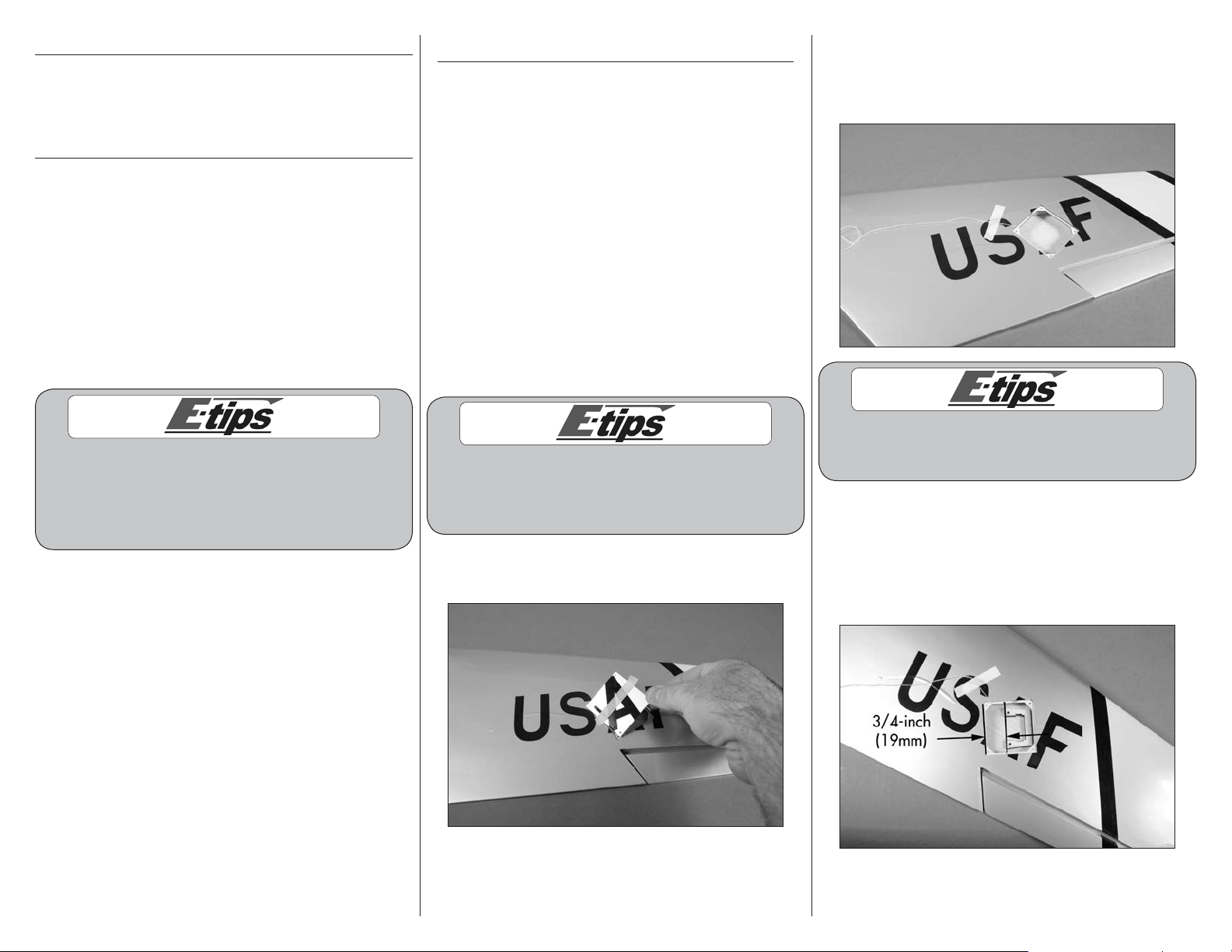
1. Remove the wood servo cover from the wing. Set
the cover aside.
2. Relocate the string from the aileron opening so
it is near one of the corners. This allows full access
to the opening and prevents accidentally gluing the
string into the wing.
DO NOT remove the string from the wing. The
string will be used to pull the aileron servo
lead through the wing later in this section.
3. Measure and mark the opening for the aileron
servo 3/4-inch (19mm) from the edge closest to
the wing root as shown. The edge of the aileron
servo mount will align with these marks when it is
installed. Center the mount fore/aft in the opening
for the aileron servo.
4 E-flite F-86 Sabre 15 DF ARF Assembly Manual
Page 5
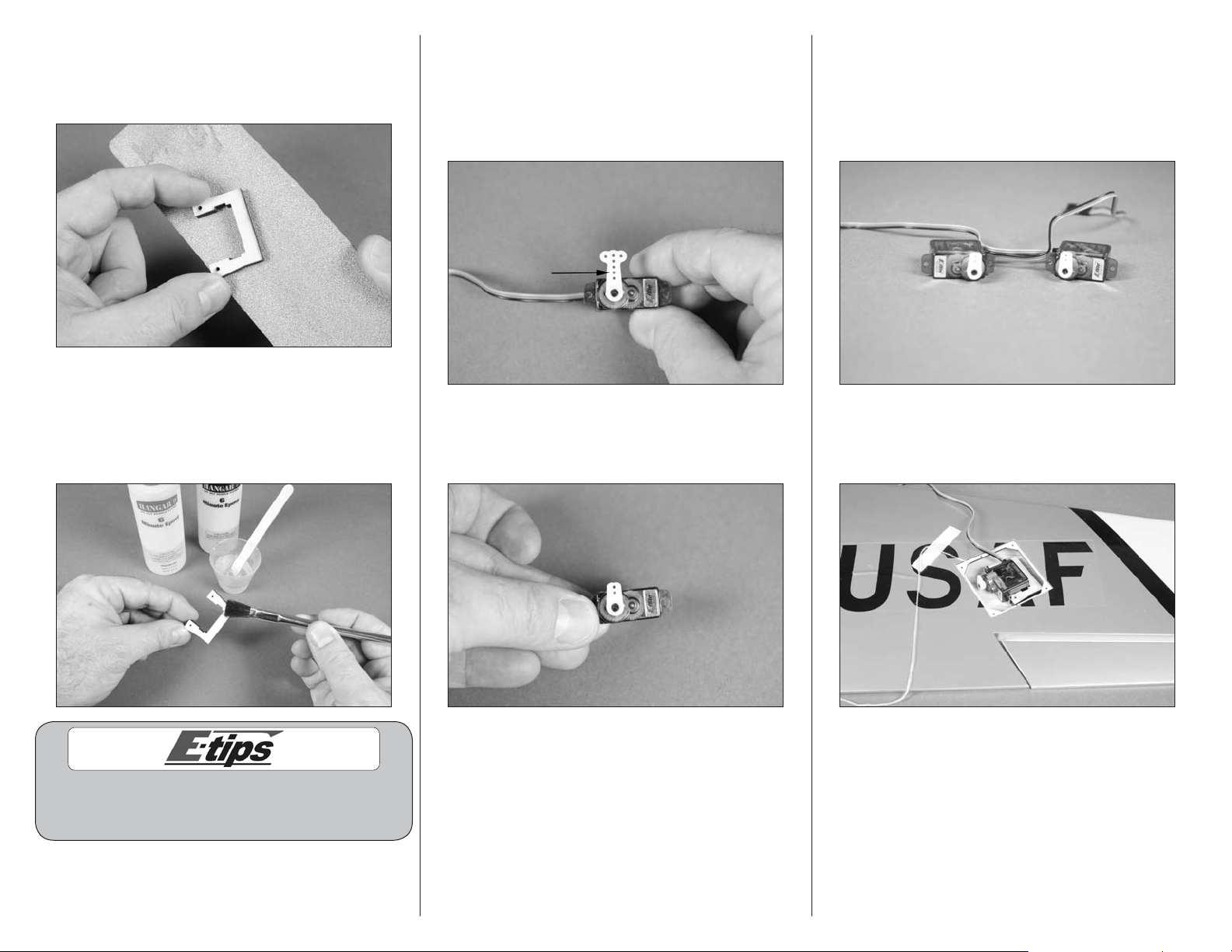
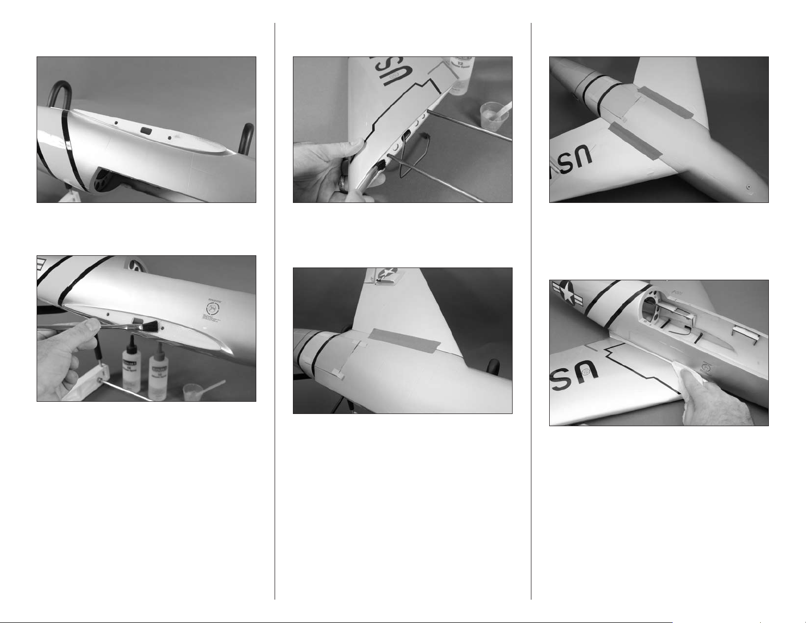
4. Lightly sand the aileron servo mount using
medium grit sandpaper. This allows the glue to
penetrate into the mount and provides a better
bond between the mount and wing.
5. Mix a small amount of 6-minute epoxy and
brush it onto the side of the aileron servo mount
that was sanded in the previous step. Position the
mount in the wing as shown in Step 3 and allow
the epoxy to fully cure before proceeding.
6. Use a hobby knife with a #11 blade to enlarge
the hole in the servo arm indicated in the photo.
Only open the hole in the servo arm enough for the
aileron linkage to fit in. Making it larger will only
create a poor fit between the linkage and servo
arm and make it difficult to trim your aircraft.
7. Use a hobby knife and #11 blade or side cutters
to remove the excess servo arm so it does not
interfere with the servo cover when it is installed.
8. Prepare a second aileron servo as shown in
Steps 6 and 7. Note the servos will be a mirror
image of each other. Plug the aileron servos into
the receiver and use the transmitter to center the
servos. Also check that they are operating correctly
at this time.
9. Position the aileron servo in the servo mount as
shown in the image with the horn facing the front
of the wing.
While waiting for the epoxy to dry on one wing
panel, you can repeat the previous steps to glue the
remaining servo mount into the opposite wing panel.
5E-flite F-86 Sabre 15 DF ARF Assembly Manual
Page 6
10. Use a #1 Phillips screwdriver and two 2.5mm
x 12 sheet metal screws to secure the servo in the
servo mount using the servo mounting strap. Install
one screw and only turn it one or two turns, then
install the second screw. Tighten the strap with even
pressure at both the front and back of the servo.
12. Tie the string around the end of the servo lead
as shown.
Aileron Linkage Installation
Required Parts
Transmitter Receiver
Aileron pushrod keeper (2)
Aileron pushrod wire, 2 9/16-inch (65mm) (2)
Servo cover (2)
Aileron control horn (2) Clear tape
Required Tools and Adhesives
Side cutters Medium CA
Pin vise Low-tack tape
Felt-tipped pen Hobby knife with #11 blade
Needle-nose pliers Hobby scissors
Drill bit: 1/16-inch (1.5mm), 5/64-inch (2mm)
Use care when installing the servo mounting strap.
Over-tightening the strap could stress the wing sheeting
and even push the servo through the top of the wing.
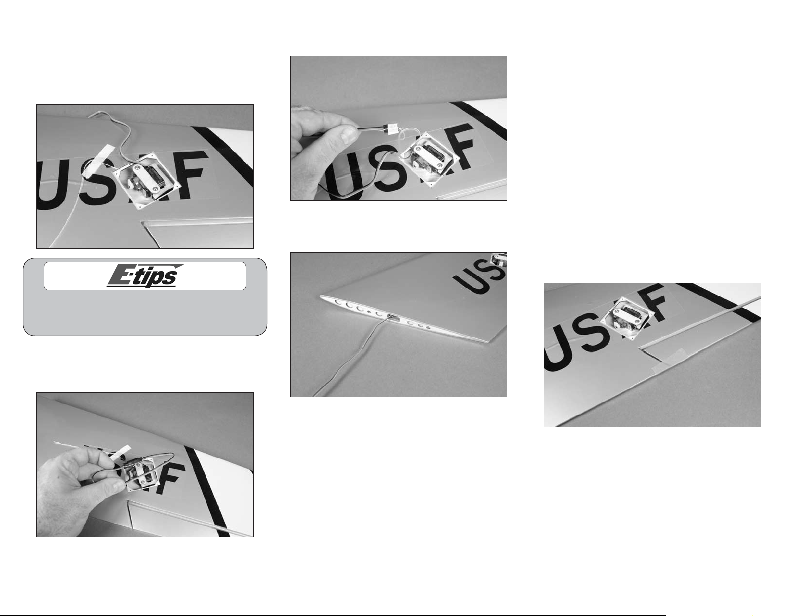
11. Use string or dental floss to secure a 9-inch
(228mm) servo extension to the lead from the
aileron servo.
13. Carefully pull the aileron servo lead through the
wing using the string tied to it in the previous step.
14. Repeat Steps 1 through 13 to install the
remaining aileron servo.
1. Use a small piece of low-tack tape to keep
the aileron centered with the trailing edge of the
wing. This will make the installation of the linkage
much easier.
6 E-flite F-86 Sabre 15 DF ARF Assembly Manual
Page 7
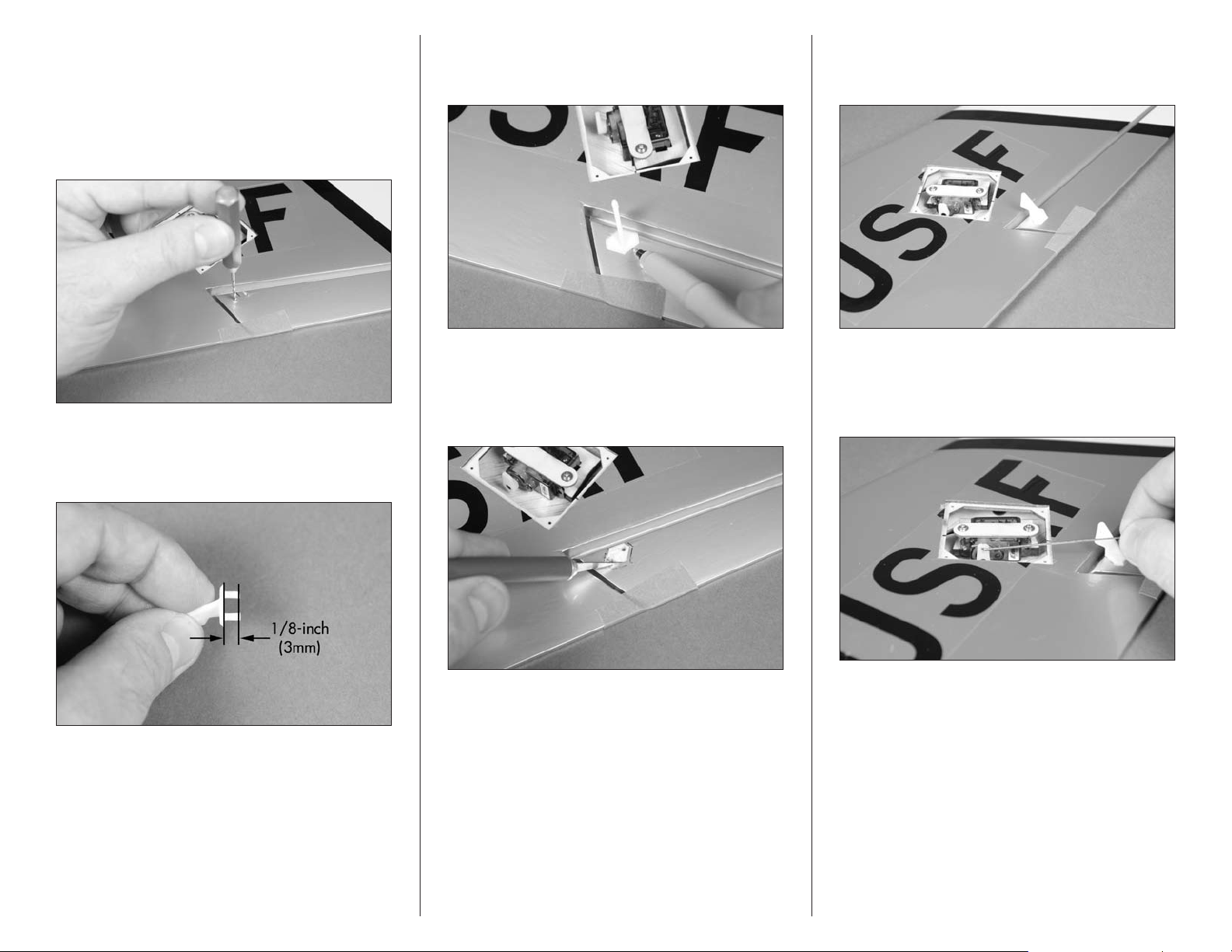
2. Locate the two holes for the aileron control horn
in the aileron. The holes should be located directly
behind the servo arm. Use a hobby knife with a
#11 blade or pin vise with a 1/16-inch (1.5mm)
drill bit to remove the covering for the aileron
control horn. Use care not to accidentally make
holes through to the top of the aileron.
4. Insert the pins of the control horn into the holes
in the aileron. Use a felt-tipped pen to trace the
outline of the control horn onto the aileron.
6. Use medium CA to glue the control horn to the
aileron. Allow the CA to cure before proceeding to
the next step.
3. Use side cutters to trim the pins on the control
horn to a length of 1/8-inch (3mm) so they don’t
extend through the top of the aileron.
5. Remove the control horn. Use a hobby knife with
a #11 blade to trim the covering 1/32-inch (1mm)
inside the lines drawn. Don’t cut into the underlying
wood as you could possibly weaken the structure.
7. Connect the Z-bend of the 2 9/16-inch (65mm)
aileron pushrod wire to the hole in the servo horn
as shown.
7E-flite F-86 Sabre 15 DF ARF Assembly Manual
Page 8
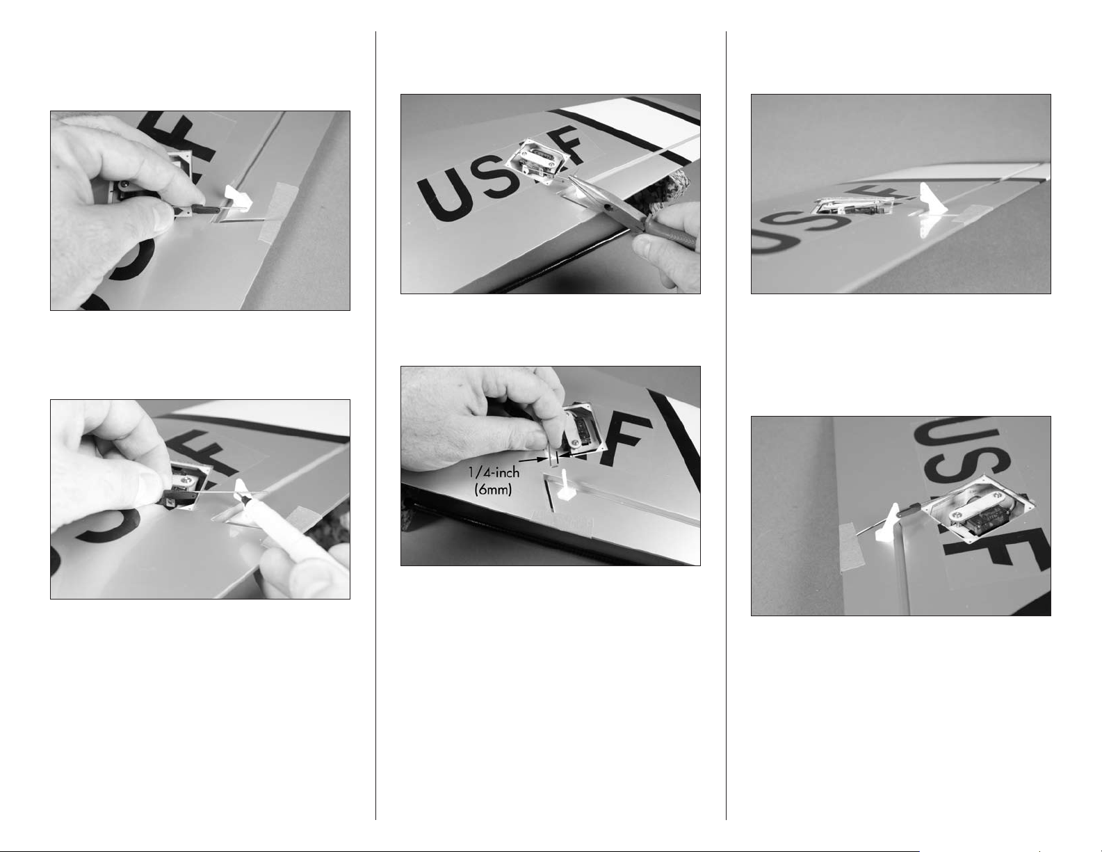
8. Slide the pushrod connector onto the pushrod
wire at this time. The connector can’t be installed
after the wire has been bent to fit into the control
horn so it must be positioned at this time.
10. Use pliers to make a 90-degree bend in the
pushrod wire. The bend must be angled to fit into
the control horn.
12. Insert the pushrod wire into the hole of the
control horn that is two holes up from the control
surface as shown.
9. With the aileron servo centered and the radio
system on, use a felt-tipped pen to mark the wire
where it crosses the hole of the control horn as shown.
11. Use side cutters to trim the wire 1/4-inch
(6mm) from the bend as shown.
13. Use pliers to open the pushrod keeper just
enough to slip it over the bend of the pushrod
wire so it secures the pushrod wire to the control
horn. Don’t open the connector too far as it could
possibly break the connector.
8 E-flite F-86 Sabre 15 DF ARF Assembly Manual
Page 9
14. Use a hobby knife and #11 blade or hobby
scissors to trim the aileron servo cover. Lines have
been embossed on the cover to be used as a guide.
Make sure the opening for the linkage is angled
slightly so the linkage doesn’t bind on the cover.
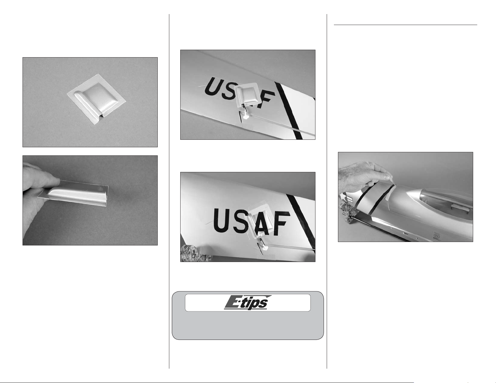
15. Use the tape provided with the model to attach
the cover to the wing. Make sure the aileron servo
can operate without having the linkage binding on
the cover.
16. Apply the decal to the servo cover. Take your
time to fit the decal to the contours of the cover.
Mounting the Main Wing Panels
Required Parts
Left wing assembly Right wing assembly
Carbon wing rod, 9-inch (230mm)
Carbon wing rod, 13-inch (330mm)
Fuselage assembly
Required Tools and Adhesives
12-minute epoxy Mixing cup
Mixing stick Epoxy brush
Paper towel Rubbing alcohol
Low-tack tape Sandpaper
Sanding Bar
1. Remove the shipping tape that holds the canopy
to the fuselage.
17. Repeat Steps 1 through 16 to install the
remaining aileron linkage and servo cover.
Cut the portions of the letters from the decal
sheet to apply to the cover to complete
the form of the covered letters.
9E-flite F-86 Sabre 15 DF ARF Assembly Manual
Page 10
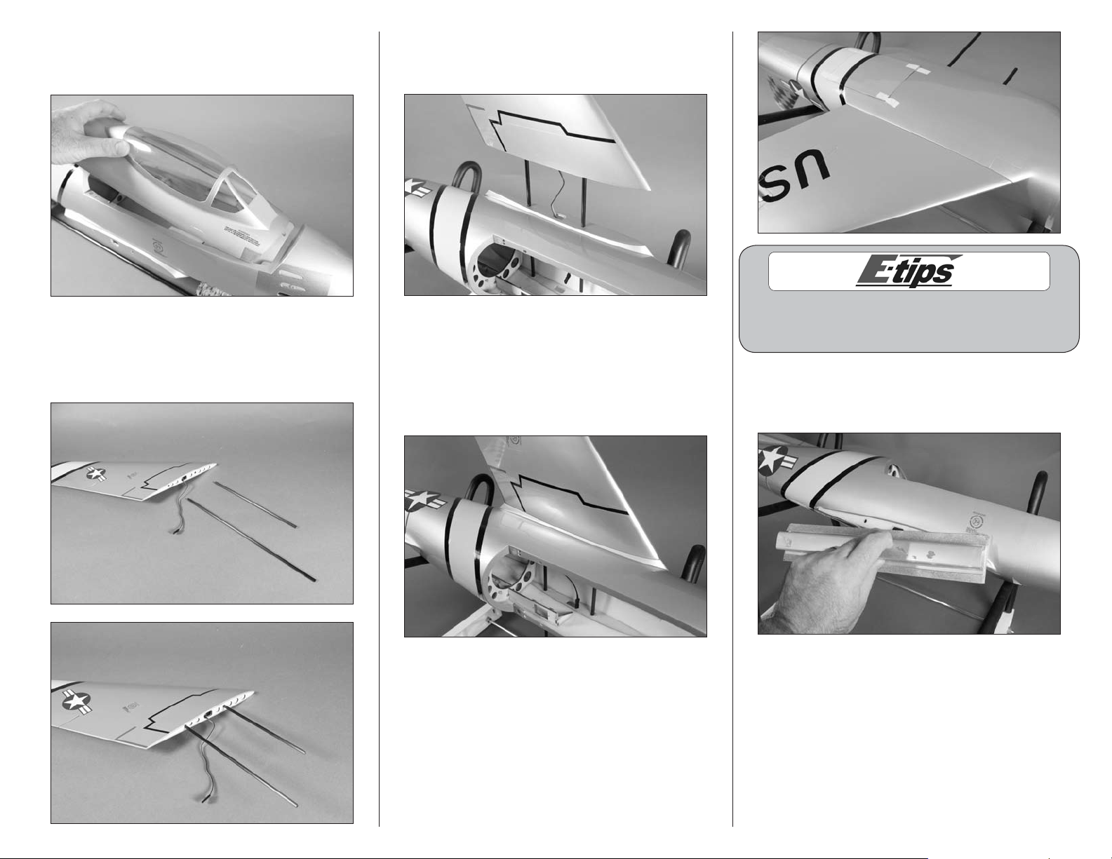
2. Carefully lift the canopy hatch from the fuselage.
The canopy is held in position by magnets and
alignment pegs at the rear and a peg at the front.
3. Slide the short and long wing rods into one
of the wing panels. The longer wing rod will be
inserted near the trailing edge of the wing, and the
shorter rod toward the leading edge of the wing.
4. Slide the wing tubes into the fuselage. Make sure
to guide the aileron servo extension into the fuselage
so the wing can fit tight against the fuselage.
5. Look at the fit of the wing to the fuselage on both
the top and bottom. You will need to use sandpaper
to remove the paint from the fuselage where the
wing fits or the epoxy won’t hold the wing securely
to the fuselage. You also don’t want to sand too
much and ruin the paint on the fuselage.
You can use low-tack tape to make an outline about
a 1/16-inch (1.5mm) inside the wing outline on the
fuselage to prevent it from scratching the paint.
6. Remove the wing from the fuselage. Use medium
grit sandpaper to remove the paint from the
fuselage where the wing fits.
10 E-flite F-86 Sabre 15 DF ARF Assembly Manual
Page 11
7. Repeat Steps 1 through 6 to prepare the
opposite side of the fuselage for the wing.
10. Apply a thin coat of 15-minute epoxy on the
end of the wing that will butt against the fuselage.
12. Repeat Steps 8 through 11 to install the
remaining wing panel to the fuselage.
8. Apply a thin layer of 15-minute epoxy to the
fuselage where it was sanded previously.
9. Apply a thin layer of 15-minute epoxy to the
short and long wing rods before you insert them
into the wing.
11. Slide the wing into position against the
fuselage. Use low-tack tape to keep the wing tight
against the fuselage until the epoxy fully cures.
13. Before the epoxy cures, use a paper towel
and rubbing alcohol to remove any excess epoxy
that may have oozed out from the joint between
the wing and fuselage.
11E-flite F-86 Sabre 15 DF ARF Assembly Manual
Page 12
Stabilizer Installation
Required Parts
Stabilizer jig center Stabilizer jig side (2)
Right stabilizer Left stabilizer
Airframe assembly
Required Tools and Adhesives
Medium CA Square
6-minute epoxy Mixing cup
Mixing stick Epoxy brush
Paper towel Rubbing alcohol
Low-tack tape Waxed paper
Ruler Felt-tipped pen
Hobby knife with #11 blade
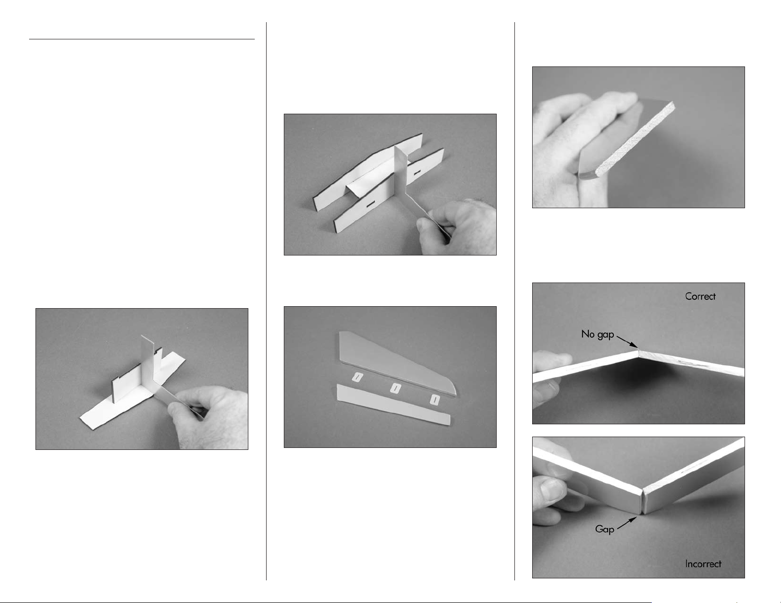
1. Use a square and medium CA to glue the
stabilizer jig center to the stabilizer jig side. The
square will keep the center perpendicular to the
side and result in a straight jig. Not doing so
may result in the jig being crooked and could
produce the wrong angle when gluing the
stabilizer halves together.
2. Use a square and medium CA to glue the
stabilizer jig side to the structure assembled
in Step 1. Using a square will keep the side
perpendicular to the stabilizer jig center. Not
doing so may result in the jig being crooked and
could produce the wrong angle when gluing the
stabilizer halves together.
3. Separate the elevator from the stabilizer. Set the
elevator and hinges aside at this time.
4. Use a hobby knife and a #11 blade to remove
the covering from the end of both the left and
right stabilizers.
5. The stabilizer halves have been prepared at the
factory with an angle so they fit tightly together
when joined. If the fit is incorrect, the two halves
will not fit tightly together.
12 E-flite F-86 Sabre 15 DF ARF Assembly Manual
Page 13
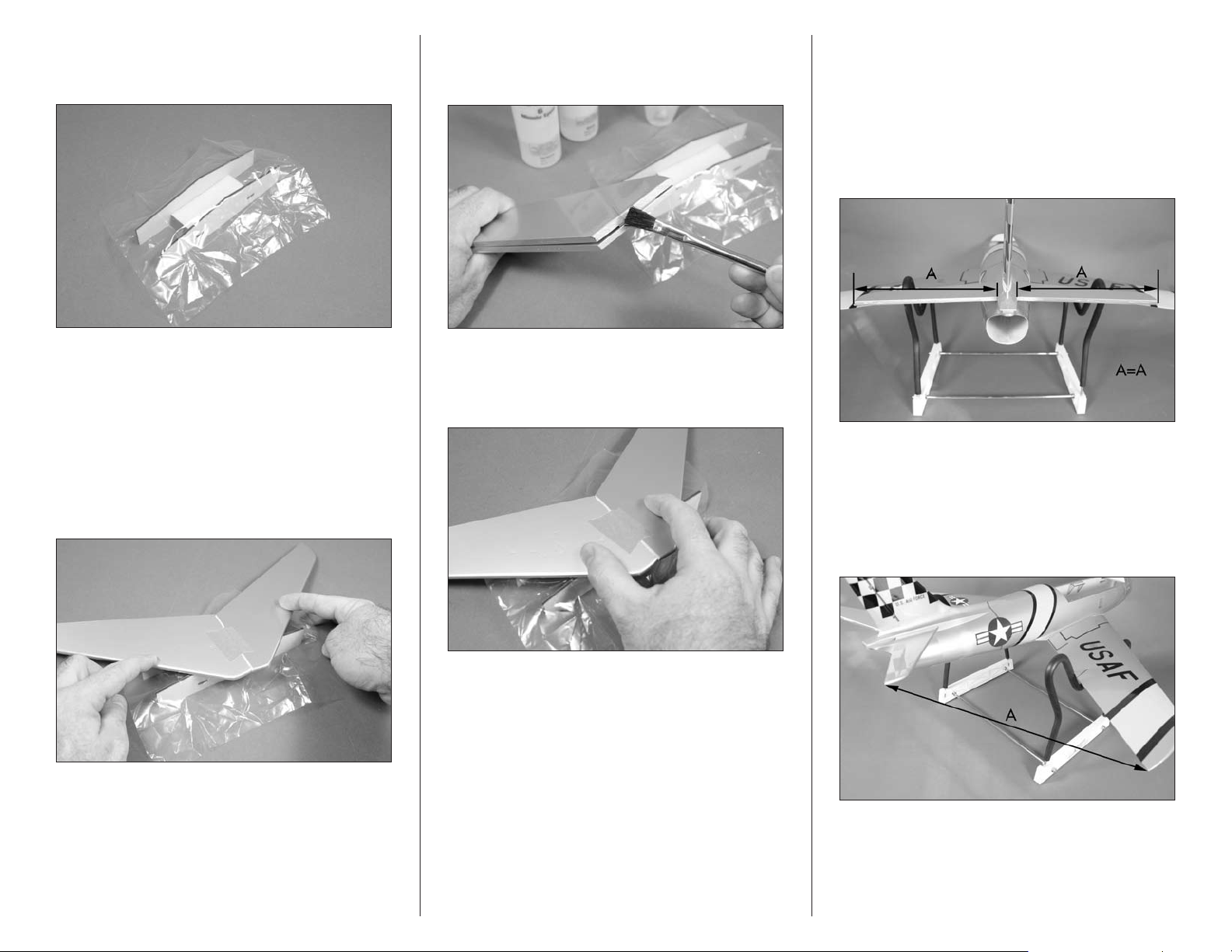
6. Place a piece of clear plastic or waxed paper
over the stabilizer jig to prevent gluing the
stabilizer directly to the jig.
8. Mix a small amount of 6-minute epoxy and use
an epoxy brush to apply a thin layer of epoxy on
the edges of each stabilizer half.
10. Slide the stabilizer into the slot in the fuselage.
Make sure that they are installed in the fuselage
with dihedral as shown in Step 12. Measure the
distance from the fuselage to the tip of the stabilizer
on both sides of the fuselage. Both measurements
must be equal. If they are not, reposition the
stabilizer and re-measure until both measurements
are equal on both sides of the fuselage.
7. Position the two stabilizer halves together
(remember the angle) and align the front edges
of the stabilizer halves. Use a small piece of lowtack tape to act as a hinge and keep the halves
aligned. Position the stabilizer assembly on the
jig to make sure the halves can rest against the
jig without forcing them. If not, you will need to
make a small gap between the two halves before
taping them together.
9. Position the stabilizer on the jig and either hold
it or use weights to keep the halves tight against the
jig until the epoxy fully cures.
11. Measure the distance from the wing tip to
the stabilizer tip on both the right and left of the
aircraft. Both measurements must be equal. If not,
readjust the stabilizer and re-measure until the
measurement is the same on both the left and right
of the aircraft.
13E-flite F-86 Sabre 15 DF ARF Assembly Manual
Page 14
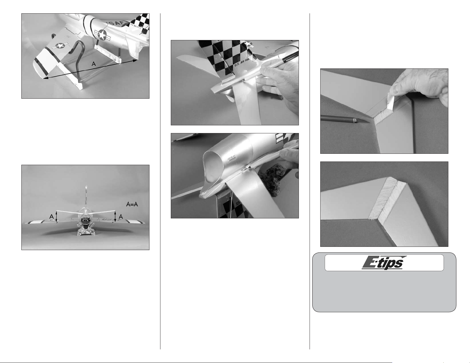
12. Step back about 4–5 feet (1.2–1.5 meters)
and view the fuselage from the rear. Check that the
stabilizer is in alignment with the wing by checking
the stabilizer tips against the wing. Both stabilizer
tips should align with the wing trailing edge. Adjust
the position of the stabilizer if necessary for correct
stabilizer alignment.
13. Use a felt-tipped pen to trace the outline of
the fuselage onto the top, bottom, left and right
of the stabilizer.
14. Remove the stabilizer from the fuselage.
Carefully use a hobby knife to remove the covering
1/16-inch (1.5mm) from inside the lines. Use light
pressure with a new #11 blade to avoid cutting
into the underlying wood. You will need to trim the
covering from the top and bottom of the stabilizer
at this time.
Other options other than a hobby knife are to
use a hot knife (with a new blade) or a soldering
iron for cutting the covering. These will melt
the covering and lower the chances of cutting
into the wood structure of the stabilizer.
14 E-flite F-86 Sabre 15 DF ARF Assembly Manual
Page 15

15. Reinstall the stabilizer and check all of the
alignments from steps 10–12. Use medium CA to
glue the stabilizer to the fuselage. Apply a bead
of CA to the joint inside the fuselage, both right
and left. Wick thin CA on the top of the stabilizer/
fuselage joint by holding the nose down. Use care
not to let the CA wick out on the outside of the
fuselage or stabilizer.
Elevator Installation
Required Parts
Elevator (left and right)
CA hinge (6)
Required Tools and Adhesives
Thin CA T-pins
1. Place a T-pin in the center of three of the elevator
hinges. This will help center them equally in the
stabilizer and elevator when they are installed.
3. Place the elevator into position. The hinges will
fit into the pre-cut slots in the stabilizer.
4. Position the elevator tight against the stabilizer.
There should be just a slight gap between the
elevator and the stabilizer. Check that the tips of
the elevator and stabilizer align with each other.
Use a paper towel and rubbing alcohol to
remove the lines from the stabilizer and fuselage
before gluing the stabilizer in position.
2. Slide the three hinges into the slots that have
been pre-cut into the elevator.
15E-flite F-86 Sabre 15 DF ARF Assembly Manual
Page 16

5. Use thin CA to glue the three hinges. Apply CA
to the top and bottom of each hinge, enough that it
fully soaks into the hinge.
DO NOT use CA accelerator on the hinges.
The CA must be allowed to soak into the hinge
to fully penetrate the hinge and surrounding
wood. Accelerator will not allow the CA to soak
into the hinge and will result in a poor bond
between the hinge and surrounding wood.
7. Break in the elevator hinges by moving the
elevator through its range of motion a few times.
This will help in reducing the initial load on the
servo and make the control surfaces easier to
move initially.
Rudder Installation
Required Parts
Fuselage assembly Pin hinge (3)
Required Tools and Adhesives
Side cutter 6-minute epoxy
Petroleum jelly Toothpick
Paper towel Rubbing alcohol
Mixing cup Mixing stick
1. Remove the shipping tape from the rudder and
fuselage. Separate the rudder from the fuselage.
6. Once the CA has fully cured, lightly pull on the
elevator and stabilizer to make sure the hinges are
secure. If not, apply additional CA to the hinges
that are not secure.
8. Repeat Steps 1 through 7 to install the
remaining elevator.
16 E-flite F-86 Sabre 15 DF ARF Assembly Manual
2. Apply a small amount of petroleum jelly to the
knuckle of each of the rudder hinges. Use care not
to get any petroleum jelly on the main parts of the
hinge. Use side cutters to trim down the hinges that
fit at the top and center of the rudder as shown.
Page 17

3. Test fit the hinges into the rudder. Each of the
Hinge point
of rudder
Hinge point recessed in control surface
hinges will fit with the pin in the knuckle recessed
in the hinge line as shown. The hinge line of the
rudder is set back from the edge of the rudder as
illustrated in the second photo.
4. Check the fit of all three hinges. The top two
may require adjustments if not trimmed properly
in Step 2.
5. Mix a small amount of 6-minute epoxy. Apply
the epoxy in each hinge pocket using a toothpick.
Also apply a small amount of epoxy to each hinge
where it fits into the pockets of the rudder.
6. Insert the hinges in the rudder. Make sure each
hinge can operate 90-degrees to the hinge line
as shown before the epoxy begins to cure. Use
rubbing alcohol and a paper towel to remove any
excess epoxy from the hinges or rudder.
7. After the epoxy has fully cured, work each hinge
through its range of motion check that the hinges
have no epoxy in the knuckle.
17E-flite F-86 Sabre 15 DF ARF Assembly Manual
Page 18

8. Check the fit of the rudder to the fin. Start by
setting the hinges for about 45-degrees of throw.
Insert the bottom hinge, then work upward inserting
the middle then top hinge.
9. Once the fit has been checked, use 6-minute
epoxy to glue the hinges in place. You will need to
remove the rudder so you can use a toothpick to
apply epoxy in the hinge pockets of the fuselage
and to the hinges. Use rubbing alcohol and a
paper towel to remove any excess epoxy from the
hinges or rudder.
Elevator Servo and
Linkage Installation
Required Parts
Transmitter Servo with hardware
Receiver Assembled airframe
2mm nut 3mm x 4mm machine screw
2mm washer Elevator control horn (2)
Pushrod connector (large)
Elevator pushrod keeper (2)
Elevator pushrod wire, 19 11/16-inch (500mm) (2)
Required Tools and Adhesives
Side cutter Hobby knife with #11 blade
Needle-nose pliers Medium CA
Pin vise Drill bit: 5/64-inch (2mm)
Threadlock Felt-tipped pen
Thin CA Phillips screwdriver: #1
10. Once the epoxy has fully cured, work the
rudder through its range of motion a number of
times to make sure there is no epoxy in the knuckle.
1. Remove the screw holding the servo horn to the
servo using a #1 Phillips screwdriver. Use the radio
system to center the elevator servo so the shorter
arm is positioned as shown. The pushrod connector
will attach to this arm.
18 E-flite F-86 Sabre 15 DF ARF Assembly Manual
Page 19

2. Remove the arm from the servo. Use side cutters
to remove any arms that will not be used.
5. Slide a 2mm washer on the threaded end of the
pushrod connector.
7. Install the servo horn on the servo using the screw
provided with the servo and a #1 Phillips screwdriver.
3. Use a pin vise and 5/64-inch (2mm) drill bit to
enlarge the hole in the servo arm.
4. Insert the pushrod connector in the hole. It
should move freely in the hole but not have
excessive slop.
8. Install the servo grommets and brass eyelets
in the servo.
Always use threadlock on metal-to-metal fasteners
to prevent them from vibrating loose.
6. Install the 2mm nut on the pushrod connector.
Don’t over-tighten the nut causing the pushrod
connector not to move. The nut should be just tight
enough, so the connector can rotate freely. Make
sure to secure this nut with threadlock or CA.
19E-flite F-86 Sabre 15 DF ARF Assembly Manual
Page 20

Do not enlarge the holes in the fuselage rails
as some are used for the hatch alignment.
9. Use a #1 Phillips screwdriver to thread the servo
mounting screw into the four holes for mounting the
elevator servo.
11. Secure the elevator servo in the fuselage using
the screws provided with the servo and a #1
Phillips screwdriver.
13. Use side cutters to trim the pins on the control
horn to a length of 3/32-inch (2mm) so they don’t
extend through the top of the elevator.
10. Place 2–3 drops of thin CA in each hole to
harden the surrounding wood. This will harden the
wood, making the screws more secure.
12. Use a hobby knife and #11 blade to remove
the covering to expose the holes to mount the
elevator control horn. Use care not to poke through
the hole to the top of the elevator.
14. Position the horn on the elevator. Use a felt-tipped
pen to trace the outline of the horn on the elevator.
20 E-flite F-86 Sabre 15 DF ARF Assembly Manual
Page 21

15. Use a hobby knife with a #11 blade to
1/16-inch
(1.5mm)
1-inch
(25mm)
remove the covering 1/32-inch (1mm) inside
the line drawn.
16.Use medium CA to glue the control horn to the
elevator. Allow the CA to cure before proceeding to
the next step.
17. Slide a pushrod connector on the 19 11/16-inch
(500mm) pushrod wire.
18. Bend the pushrod wire as shown so it does not
bind when operating the elevator. You will need to
make a left and right pushrod.
19. Slide the pushrod wire into the pushrod tube in
the fuselage closest to the elevator. Guide it into the
connector on the servo at this time also.
20. Insert the pushrod wire into the hole of the
control horn that is two away from the control
surface as shown. Use pliers to open the pushrod
keeper just enough to slip it over the bend of the
pushrod wire so it secures the pushrod wire to the
control horn. Don’t open the connector too far as it
could possibly break the connector.
21E-flite F-86 Sabre 15 DF ARF Assembly Manual
Page 22

21. Repeat Steps 12 through 19 to install the
remaining control horn and pushrod wire.
Always use threadlock on metal-to-metal fasteners
to prevent them from vibrating loose.
22. Center both elevator halves and the elevator
servo. Use a 3mm x 4mm machine screw to secure
the pushrod wires in the pushrod connector. Use
a #1 Phillips screwdriver to tighten the screw.
Use side cutters to trim the excess pushrod wire
extending past the pushrod connector.
Rudder Servo and
Linkage Installation
Required Parts
Transmitter Servo with hardware
Receiver Assembled airframe
Nylon pushrod backplate
Micro pushrod connector
2mm x 4mm machine screw
Pushrod connector (large)
Rudder pushrod keeper
Rudder pushrod wire, 19 11/16-inch (500mm) (2)
Required Tools and Adhesives
Side cutter Hobby knife with #11 blade
Medium CA Threadlock
Pin vise Drill bit: 1/16-inch (1.5mm)
6-minute epoxy Mixing cup
Mixing stick Paper towels
Rubbing alcohol Thin CA
Phillips screwdriver: #1
1. Use 6-minute epoxy to glue the control
horn to the rudder. Allow the epoxy to fully
cure before proceeding.
2. Use the radio system to center the rudder servo.
Note the direction of the servo arm in relationship
to the servo.
3. Use a pin vise and 1/16-inch (1.5mm) drill bit
to enlarge the hole in the servo arm as shown.
22 E-flite F-86 Sabre 15 DF ARF Assembly Manual
Page 23

4. Use a hobby knife and #11 blade or side cutters
to remove the excess servo arm so it does not
interfere with the intake tube when it is installed.
5. Insert the micro pushrod connector in the hole. It
should move freely in the hole.
6. Install the nylon backplate on the pushrod
connector to secure the connector to the servo horn.
7. Use a #1 Phillips screwdriver to thread the servo
mounting screw into the two holes for mounting the
elevator servo.
8. Place 2–3 drops of thin CA in each hole to
harden the surrounding wood. This will harden the
wood, making the screws more secure.
9. Secure the rudder servo in the fuselage using
the screws provided with the servo and a #1
Phillips screwdriver.
23E-flite F-86 Sabre 15 DF ARF Assembly Manual
Page 24

10. Slide a pushrod connector on the 19 11/16-inch
(500mm) pushrod wire.
11. Insert the pushrod wire into the outside hole of
the control horn. Slide the rudder pushrod in the
hole of the pushrod connector. Use pliers to open
the pushrod keeper just enough to slip it over the
bend of the pushrod wire so it secures the pushrod
wire to the control horn. Don’t open the connector
too far as it could possibly break the connector.
12. Center the rudder and the rudder servo. Use a
2mm x 4mm machine screw to secure the pushrod
wires in the pushrod connector. Use a #1 Phillips
screwdriver to tighten the screw. Use side cutters
to trim the excess length of the pushrod wire so it
does not interfere with the operation of the servo.
Landing Gear Installation
Required Parts
Nose gear wire Wheel collar (7)
Main gear wire, left
Main gear wire, right
3mm x 3mm setscrew
Landing gear strap (2)
Nose gear steering arm
2mm x 8mm machine screw (7)
Nose wheel, 1 3/16-inch (30mm)
Main wheel, 1 5/8-inch (41mm) (2)
2mm x 8mm sheet metal screw (4)
Required Tools and Adhesives
Phillips screwdriver: #1
Hex wrench: 1.5mm Threadlock
1. Insert the main landing gear into the notch in
the wing. The wire will fit flush with the wing when
installed. There is a left and right main gear wire.
When positioned correctly the spring coil will face
the rear as shown in the photos.
24 E-flite F-86 Sabre 15 DF ARF Assembly Manual
Page 25

2. Use a #1 Phillips screwdriver to tighten the two
2mm x 8mm sheet metal screws that secure the
landing gear strap to the bottom of the wing. The
holes for the straps are pre located in the wing.
3. Slide a wheel collar on the main landing gear
and use a #1 Phillips screwdriver and 2mm x 8mm
machine screw to secure the wheel collar to the
wire. The wheel collars have a slight flange which
faces toward the wheel. Make sure to install the
wheel collars in the correct direction.
4. Slide a main wheel and wheel collar onto the
landing gear wire. Use a #1 Phillips screwdriver
and 2mm x 8mm machine screw to secure the
wheel. Remember to use threadlock on the screw to
prevent it from vibrating loose.
Leave a very small gap between the wheels and
each collar to allow the wheel to roll freely.
7. Install the nose wheel on the nose gear
wire using two wheel collars and a #1 Phillips
screwdriver to tighten the two 2mm x 8mm
machine screws.
Always use threadlock on metal-to-metal fasteners
to prevent them from vibrating loose.
5. Repeat Steps 1 through 4 to install the remaining
main gear wire and wheel.
6. Position a wheel collar on the nose gear wire as
shown and thread a 2mm x 8mm machine screw in
the wheel collar. Note that the flange on the collar
faces away from the spring on the nose gear wire.
Do not tighten the screw at this time.
8. Slide the nose gear wire into the bushing in the
front of the fuselage. The gear will angle forward
as shown in the photo.
25E-flite F-86 Sabre 15 DF ARF Assembly Manual
Page 26

During manufacturing the end of the nose gear wire
may be slightly enlarged due to cutting. If this happens
use a file to reduce the diameter of the end of the
wire so that it slides smoothly through the bushings.
9. Slide the steering bellcrank on the nose gear
wire from inside the fuselage. Use a 1.5mm hex
wrench and 3mm x 3mm setscrew to secure the
steering arm to the nose gear wire. The nose gear
wire will fit flush at the top of the steering arm. The
setscrew will tighten onto the flat spot of the nose
gear that can be seen in the photo in Step 6. Make
sure to use threadlock on the setscrew to prevent
it from vibrating loose. Tighten the collar on the
bottom so the nose gear turns freely but will not
slide up and down on the bushing.
Steering Servo and
Linkage Installation
Required Parts
Assembled airframe Steering linkage
Transmitter Receiver
Steering servo Servo mount
Servo mounting strap
Nose gear pushrod wire, 7 7/8-inch (200mm)
2.5mm x 10mm sheet metal screw (4)
Required Tools and Adhesives
Pin vise Drill bit: 5/64-inch (2mm)
6-minute epoxy Mixing stick
Sandpaper Felt-tipped pen
Mixing cup Phillips screwdriver: #1
1. Insert the Z-bend for the nose gear pushrod wire
into the steering bellcrank.
2. Use the radio system to center the steering servo.
Note the direction of the servo arm in relationship
to the servo.
3. Use a pin vise and 5/64-inch (2mm) drill bit to
enlarge the hole in the servo arm that is four holes
away from the center of the servo arm as shown.
Check to make sure the nose gear wire
can move freely so the steering servo is not
overloaded when trying to steer your aircraft.
26 E-flite F-86 Sabre 15 DF ARF Assembly Manual
Page 27

4. Insert the steering pushrod in the hole of the
servo arm. Position the servo so the nose gear is
aligned with the fuselage centerline so it will taxi
straight down the runway. Use a felt-tipped pen to
mark the fuselage where the servo rests.
5. Lightly sand the seam in the fuselage where the
steering servo rests. This provides a flat area for the
mount to be glued.
6. Use 6-minute epoxy to glue the servo mount in
the fuselage. Once the epoxy fully cures, secure
the servo using the servo mounting strap and two
2.5mm x 10mm sheet metal screws. Tighten the
screws using a #1 Phillips screwdriver.
Check to make sure the nose gear wire
can move freely so the steering servo is not
overloaded when trying to steer your aircraft.
Speed Control and
Receiver Installation
Required Parts
Assembled airframe
Speed control Receiver
Hook and loop tape
Required Tools and Adhesives
Hobby scissors
1. Cut a piece of hook and loop tape and apply it
to the bottom of the speed control as shown. Leave
the adhesive backing on the mating hook and loop
until instructed to do so.
2. Remove the backing from the hook and loop
tape on the speed control. Secure the speed control
inside the fuselage as shown.
27E-flite F-86 Sabre 15 DF ARF Assembly Manual
Page 28

Note: When flying your model in locations
High-Temperature ESC Location
Cut hole for ESC cooling
where the air temperature is very high, you will
need to mount the ESC between the wing rods.
Cut a hole in the bottom of the fuselage so the
fins of the ESC can be exposed to the air flow
outside of the fuselage. This keeps the ESC cool
and prevents over-heating.
3. Insert the leads from the speed control through
the hole in the former in the fuselage as shown.
4. Use a small amount of hook and loop tape to
mount the switch from the speed control to the side
of the fuselage. Make sure to position it where it
can be easily accessed.
5. Cut two pieces of hook and loop tape and apply
it to the bottom of the main and remote receivers as
shown. Leave the adhesive backing on the mating
hook and loop until instructed to do so.
4. Plug the leads from the aileron servos, elevator
servo, steering servo and speed control into the
appropriate ports of the receiver. Use hook and
loop tape to attach the receiver inside the fuselage
as shown in the photo.
28 E-flite F-86 Sabre 15 DF ARF Assembly Manual
Page 29

5. When installing a remote receiver, attach it as
shown in the fuselage using hook and loop tape.
Intake Tube Installation
Required Parts
Assembled airframe
Intake tube Hook and loop strap
1. Remove the cover from the bottom of the
fuselage and set it aside in a safe location.
2. Prepare the hook and loop strap by attaching
the pieces together using a 2-inch (52mm)
overlap as shown.
3. Locate the intake tube. The circular end will fit to
the rear of the fuselage. The front is egg-shaped to
match the intake of the fuselage and the flatter side
will face to the bottom of the fuselage.
4. Place the hook and loop tape on the intake tube
at this time. This will prevent you from accidentally
looping the tape around the steering linkage wire.
29E-flite F-86 Sabre 15 DF ARF Assembly Manual
Page 30

5. Insert the intake tube into the fuselage. Slide it
Fan bottom (fuselage top)
Fan centerline
Mounting lug
Mounting lug
forward so it keys to the intake of the fuselage. The
tube will be secured after the fan has been installed.
Fan Installation
Required Parts
Fan assembly Assembled airframe
Exhaust tube Fan fairing
2mm x 6mm machine screw (2)
2mm x 8mm sheet metal screw (4)
Required Tools and Adhesives
Felt-tipped pen Hobby scissors
Thin CA Phillips screwdriver: #1
Paper Low-tack tape
1. Locate the fan unit. View the fan unit and use
the drawing provided to determine the top and
bottom of the fan. Place a piece of low-tack tape
on the bottom of the fan so the bottom can easily
be determined during assembly.
2. Pass the wires through the fan fairing.
3. Use two 2mm x 6mm machine screws and a #1
Phillips screwdriver to attach the fan fairing to the
motor. Note that the fairing faces to the bottom of
the fan unit.
30 E-flite F-86 Sabre 15 DF ARF Assembly Manual
Page 31

4. Cut a paper template to locate where the fan fairing
will exit the exhaust tube. Make sure the template fits
tightly against the mounting lugs as the overall width of
the template will be used for positioning.
5. Use a felt-tipped pen to mark the edge of the fan
unit on the template. Make a mark for both of the
mounting lugs.
6. Align the template on the exhaust tube. The
marks made in the previous step will align with
the notches in the tube for the mounting lugs.
Make sure the template is on the side of the
exhaust tube with the seam (bottom). Use a felttipped pen to trace the outline for the fan fairing
on the exhaust tube.
7. Remove the template from the exhaust tube. Use
hobby scissors to trim the exhaust tube for the fan
fairing. Slot the exhaust tube so it can be slid over
the fan fairing.
8. Check the fit of the exhaust tube on the fan unit.
It may be necessary to trim the opening slightly
using hobby scissors.
Matching the colors between the ESC and motor
when they are connected results in the correct
motor direction if using all E-flite components.
9. Use a #1 Phillips screwdriver to thread a
mounting screw into the four holes for mounting the
fan unit.
31E-flite F-86 Sabre 15 DF ARF Assembly Manual
Page 32

10. Place 2–3 drops of thin CA in each hole to
harden the surrounding wood. This hardens the
wood, making the screws more secure.
11. Connect the wires from the motor to those
coming from the speed control.
12. Fit the fan unit into the fuselage with the fan
fairing facing to the bottom of the fuselage. Make
sure to fit the fan into the intake tube and that all the
screw holes for mounting the fan are visible through
the mounting lugs. Secure the fan unit in the fuselage
using four 2mm x 8mm sheet metal screws. Tighten
the screws using a #1 Phillips screwdriver.
Exhaust Tube Installation
Required Parts
Assembled airframe
Exhaust tube Clear tape
Fan access hatch
Required Tools and Adhesives
Hobby scissors Felt-tipped pen
1. Carefully roll or fold the exhaust tube into the
shape shown below. It is made of a durable clear
plastic and will not be harmed by doing so.
2. Slide the exhaust tube into the fuselage, with
the wider end of the tube entering the fuselage
from the rear. It will “pop” open when it has been
inserted fully into the fuselage.
32 E-flite F-86 Sabre 15 DF ARF Assembly Manual
Page 33

3. Position the exhaust tube so it overlaps onto the
fan assembly.
4. Use a felt-tipped pen to trace the outline of the
fuselage on the exhaust tube.
5. Remove the exhaust tube and use hobby scissors
to trim the exhaust tube at the line drawn in the
previous step to match the outline of the fuselage.
6. Insert the exhaust tube back into the fuselage.
Use the clear tape supplied with your aircraft to
tape the thrust tube to the fan housing.
7. Use clear tape at the bottom and both sides
of the thrust tube to secure the tube at the rear
of the fuselage.
8. Cut four pieces of clear tape using scissors and
tape the fan access hatch to the fuselage.
33E-flite F-86 Sabre 15 DF ARF Assembly Manual
Page 34

Securing the Intake Tube
Required Parts
Assembled airframe
Plywood intake mounting plate (2)
Plywood intake mounting gusset (4)
2mm x 6mm sheet metal screw (4)
Required Tools and Adhesives
Medium CA 6-minute epoxy
Mixing stick Thin CA
Pin vise Drill bit: 1/16-inch (1.5mm)
Mixing cup Sandpaper
1. Use medium CA to glue the two plywood intake
mounting gussets to the plywood plate. Note the
position of the pieces in the photo.
2. Place the assembly on the rest in the fuselage.
The gussets should rest lightly on the intake tube. If
they are deforming the intake tube, you may need
to sand the plywood plate or stop as necessary.
Use a pencil to mark the location for the two screws
that secure the plywood plate to the stop.
4. Use 2–3 drops of thin CA to harden the
surrounding wood for the screws. This makes the
screws more secure when they are installed.
5. Repeat Steps 1 through 4 to assemble and fit the
remaining plywood plate and gussets.
3. Use a pin vise and 1/16-inch (1.5mm) drill bit
to drill the two holes for the mounting screws.
6. Apply a small amount of 6-minute epoxy to the
plywood gussets where they contact the intake tube.
Insert the assembly into the fuselage and secure it
to the rest in the fuselage using two 2mm x 6mm
sheet metal screws and a #1 Phillips screwdriver.
Install both assemblies at this time.
34 E-flite F-86 Sabre 15 DF ARF Assembly Manual
Page 35

Canopy Assembly
Required Parts
Canopy hatch Cockpit
Clear tape Pilot figure (optional)
Required Tools and Adhesives
Hobby scissors
1. Use hobby scissors to trim the cockpit along the
molded lines.
3. Use clear tape to hold the cockpit in the
canopy hatch.
Optional Pilot
You may notice a pilot shown in the F-86 Sabre. A
pilot is not included with the kit. It can be purchased
separately under part number (PKZ7003). The pilot
was cut down to fit and was glued in with canopy
glue as shown before the cockpit was installed in the
canopy hatch.
Motor Battery Installation
Required Parts
Motor battery Hook and loop tape
Assembled airframe
Canopy hatch assembly
Required Tools and Adhesives
Hobby scissors
1. Cut a piece of hook and loop tape that is
41/2 inches (115mm) long. Apply the tape to the
intake tube so it is centered on the top of the tube
and positioned equally forward and backward of
the intake mounting plates.
2. Insert the cockpit in the canopy hatch. It is best
to insert the front first, then the rear will fit right in.
2. Apply the mating portion of the tape to the
bottom of the motor battery as shown.
35E-flite F-86 Sabre 15 DF ARF Assembly Manual
Page 36

3. Position the motor battery in the fuselage and
use the hook and loop strap to secure it inside
the fuselage.
4. Place the canopy hatch on the fuselage.
Decal Placement
Required Parts
Decal sheet Assembled airframe
Required Tools and Adhesives
Hobby scissors Hobby knife with #11 blade
1. Use hobby scissors and a hobby knife with a
#11 blade to cut the decals from the decal sheet.
Apply the decals to the airfame following one of
the schemes shown. Drawings for decal placement
are located on Page 43 of this manual.
Center of Gravity
An important part of preparing the aircraft for flight is
properly balancing the model.
Caution: Do not inadvertently skip this step!
The recommended Center of Gravity (CG) location
for your model is 5
back from the leading edge of the wing as shown with
the battery pack installed. Mark the location of the CG
on the top of the wing with a felt-tipped pen.
When balancing your model, support the plane
inverted at the marks made on the wing with your
fingers or a commercially available balancing stand.
This is the correct balance point for your model. Make
sure your model is assembled and ready for flight
before balancing.
Adjust the motor battery as necessary so the model is
level or slightly nose down. This is the correct balance
point for your model. You should find the CG to be
very close with the battery installed as shown in this
manual. Mark the location of the battery on the intake
tube using a felt-tipped pen so it can be returned to
this position if it is removed from your model.
3
/4 to 61/8 inches (145 to 155mm)
36 E-flite F-86 Sabre 15 DF ARF Assembly Manual
Page 37

After the first flights, the CG position can be adjusted
for your personal preference.
Control Throws
1. Turn on the transmitter and receiver of your
model. Check the movement of the rudder using
the transmitter. When the stick is moved right,
the rudder should also move right. Reverse the
direction of the servo at the transmitter if necessary.
2. Check the movement of the elevator with the
radio system. Moving the elevator stick toward
the bottom of the transmitter makes the airplane
elevator move up.
3. Check the movement of the ailerons with the
radio system. Moving the aileron stick right makes
the right aileron move up and the left aileron move
down.
4. Use a ruler to adjust the throw of the elevator,
ailerons and rudder. Adjust the position of
the pushrod at the control horn to achieve the
following measurements when moving the sticks to
their endpoints.
Elevator High Rate (100%)
Up 1/2-inch (12mm) +10% Exponential
Down 1/2-inch (12mm) +10% Exponential
Rudder High Rate (100%)
Right 3/8-inch (10mm) +10% Exponential
Left 3/8-inch (10mm) +10% Exponential
Rudder Low Rate (40%)
Right 3/16-inch (5mm) +5% Exponential
Left 3/16-inch (5mm) +5% Exponential
Adding spoilerons to the F-86 Sabre during landing
approach and landing will add washout affect and
decrease the floating affect. Set both ailerons so they
raise up 1/8-inch (3mm) above the trailing edge of
the wing from center. Follow your computer radio
instructions for the correct setup.
The rudder low rate is used for takeoff and landing
as the F-86 Sabre has a narrow stance gear. If
using a computer radio it is also possible to use
a mix and separate channel for the nose gear
steering to create a low rate for just the nose gear.
Elevator Low Rate (70%)
Up 5/16-inch (9mm) +5% Exponential
Down 5/16-inch (9mm) +5% Exponential
Aileron High Rate (100%)
Up 3/8-inch (10mm) +10% Exponential
Down 3/8-inch (10mm) +10% Exponential
Aileron Low Rate (80%)
Up 9/32-inch (7mm) Linear Exponential
Down 9/32-inch (7mm) Linear Exponential
Measurements are taken at the inner or
widest point on the control surface.
These are general guidelines measured from our own
flight tests. You can experiment with higher rates to
match your preferred style of flying.
Travel Adjust and Sub-Trims are not listed
and should be adjusted according to each
individual model and preference.
37E-flite F-86 Sabre 15 DF ARF Assembly Manual
Page 38

Preflight
Flying Your F-86 Sabre 15 DF
Range Test Your Radio
Check Your Radio
Before going to the field, be sure your batteries are
fully charged per the instructions included with your
radio. Charge the transmitter and motor battery
for your airplane. Use the recommended charger
supplied with your particular radio system, following
the instructions provided with the radio. In most
cases, the radio should be charged the night before
going out flying.
Before each flying session, be sure to range check your
radio. See your radio manual for the recommended
range and instructions for your radio system. Each
radio manufacturer specifies different procedures for
their radio systems. Next, run the motor. With the
model securely anchored, check the range again.
The range test should not be significantly affected. If
it is, don’t attempt to fly! Have your radio equipment
checked out by the manufacturer.
Double-check that all controls (aileron, elevator, rudder
and throttle) move in the correct direction.
Check the radio installation and make sure all the
control surfaces are moving correctly (i.e., the correct
direction and with the recommended throws).
Check all the control horns, servo horns, and clevises
to make sure they are secure and in good condition.
You will find the agile F-86 is very capable in the air
yet predictable on approach and landings.
As with all performance scale aircraft takeoff and
landings must be performed smoothly with small
control inputs. Take off using low rate steering and
full power. Hold a small amount of up elevator during
the takeoff roll and let the model fly off of the ground.
After rotation, ease off of the up elevator and climb to
altitude. Do not try to pull the model off of the ground
too soon before it has a good amount of airspeed.
Landings are best made by flying the model to the
ground with a slight positive angle of attack. Use the
throttle to control your descent and rudder to keep the
model on heading.
The F-86 Sabre tracks very well in the air and is
capable of many basic aerobatic maneuvers like
loops, slow rolls, point rolls and inverted flight. We
recommend you use throttle management during the
whole flight. Using full power throughout the duration
of the flight will result in shorter flight times and could
result in a shorter life span for the electronics and
batteries.
Happy Landings!
Before each flying session, and especially with a new
model, it is important to perform a range check. It
is helpful to have another person available to assist
during the range check. If you are using a Spektrum
transmitter, please refer to your transmitter’s manual for
detailed instructions on the range check process.
1. With the model resting on the ground, stand 30
paces (approximately 90 feet) away from the model.
2. Face the model with the transmitter in your
normal flying position. Be sure the throttle is in the
full down position and plug the flight battery into
the speed control.
3. As you move the controls, watch to be sure the
airplane’s motor and controls operate smoothly.
You should have total control of the model at 30
paces (90 feet).
4. If control issues exist, call the appropriate
Horizon Product Support office (see page 40–41)
or go to horizonhobby.com to find a local
Spektrum distributor in your country for service if
using a Spektrum radio system.
38 E-flite F-86 Sabre 15 DF ARF Assembly Manual
Page 39

Safety Do’s and Don’ts for Pilots
Daily Flight Checks
Warranty and Repair Policy
• Checkallcontrolsurfacespriortoeachtakeoff.
• Donotflyyourmodelnearspectators,parking
areas or any other area that could result in injury to
people or damage of property.
• Donotflyduringadverseweatherconditions.Poor
visibility can cause disorientation and loss of control
of your aircraft. Strong winds can cause similar
problems.
• Donottakechances.Ifatanytimeduringflightyou
observe any erratic or abnormal operation, land
immediately and do not resume flight until the cause
of the problem has been ascertained and corrected.
Safety can never be taken lightly.
• Donotflynearpowerlines.
1. Check the battery voltage of the transmitter
battery. Do not fly below the manufacturer’s
recommended voltage. To do so can crash
your aircraft.
When you check these batteries, ensure you have the
polarities correct on your expanded scale voltmeter.
2. Check all hardware (linkages, screws, nuts,
and bolts) prior to each day’s flight. Be sure that
binding does not occur and that all parts are
properly secured.
3. Ensure all surfaces are moving in the
proper manner.
4. Perform a ground range check before each
day’s flying session.
5. Prior to starting your aircraft, turn off your
transmitter, then turn it back on. Do this each time
you start your aircraft. If any critical switches are
on without your knowledge, the transmitter alarm
will sound a warning at this time.
6. Check that all trim levers are in the
proper location.
7. All servo pigtails and switch harness plugs
should be secured in the receiver. Make sure the
switch harness moves freely in both directions.
WARRANTY PERIOD
Exclusive Warranty- Horizon Hobby, Inc., (Horizon)
warranties that the Products purchased (the “Product”)
will be free from defects in materials and workmanship
at the date of purchase by the Purchaser.
LIMITED WARRANTY
Horizon reserves the right to change or modify this
warranty without notice and disclaims all other
warranties, express or implied.
(a) This warranty is limited to the original Purchaser
(“Purchaser”) and is not transferable. REPAIR OR
REPLACEMENT AS PROVIDED UNDER THIS WARRANTY
IS THE EXCLUSIVE REMEDY OF THE PURCHASER. This
warranty covers only those Products purchased from an
authorized Horizon dealer. Third party transactions are not
covered by this warranty. Proof of purchase is required for
warranty claims.
(b) Limitations- HORIZON MAKES NO WARRANTY
OR REPRESENTATION, EXPRESS OR IMPLIED, ABOUT
NON-INFRINGEMENT, MERCHANTABILITY OR FITNESS
FOR A PARTICULAR PURPOSE OF THE PRODUCT. THE
PURCHASER ACKNOWLEDGES THAT THEY ALONE
HAVE DETERMINED THAT THE PRODUCT WILL SUITABLY
MEET THE REQUIREMENTS OF THE PURCHASER’S
INTENDED USE.
(c) Purchaser Remedy- Horizon’s sole obligation hereunder
shall be that Horizon will, at its option, (i) repair or
(ii) replace, any Product determined by Horizon to be
defective. In the event of a defect, these are the Purchaser’s
exclusive remedies. Horizon reserves the right to inspect
any and all equipment involved in a warranty claim.
Repair or replacement decisions are at the sole discretion
of Horizon. This warranty does not cover cosmetic damage
or damage due to acts of God, accident, misuse, abuse,
negligence, commercial use, or modification of or to any
part of the Product. This warranty does not cover damage
due to improper installation, operation, maintenance, or
attempted repair by anyone other than Horizon. Return of
any goods by Purchaser must be approved in writing by
Horizon before shipment.
39E-flite F-86 Sabre 15 DF ARF Assembly Manual
Page 40

DAMAGE LIMITS
Warranty Services
NON-WARRANTY REPAIRS
HORIZON SHALL NOT BE LIABLE FOR SPECIAL,
INDIRECT OR CONSEQUENTIAL DAMAGES, LOSS
OF PROFITS OR PRODUCTION OR COMMERCIAL
LOSS IN ANY WAY CONNECTED WITH THE
PRODUCT, WHETHER SUCH CLAIM IS BASED IN
CONTRACT, WARRANTY, NEGLIGENCE, OR STRICT
LIABILITY. Further, in no event shall the liability of
Horizon exceed the individual price of the Product on
which liability is asserted. As Horizon has no control
over use, setup, final assembly, modification or misuse,
no liability shall be assumed nor accepted for any
resulting damage or injury. By the act of use, setup or
assembly, the user accepts all resulting liability.
If you as the Purchaser or user are not prepared
to accept the liability associated with the use of
this Product, you are advised to return this Product
immediately in new and unused condition to the place
of purchase.
Law: These Terms are governed by Illinois law (without
regard to conflict of law principals).
QUESTIONS, ASSISTANCE, AND REPAIRS
Your local hobby store and/or place of purchase
cannot provide warranty support or repair. Once
assembly, setup or use of the Product has been
started, you must contact Horizon directly. This will
enable Horizon to better answer your questions
and service you in the event that you may need any
assistance. For questions or assistance, please direct
your email to productsupport@horizonhobby.com,
or call 877.504.0233 toll free to speak to a service
technician.
INSPECTION OR REPAIRS
If this Product needs to be inspected or repaired,
please call for a Return Merchandise Authorization
(RMA). Pack the Product securely using a shipping
carton. Please note that original boxes may be
included, but are not designed to withstand the rigors
of shipping without additional protection. Ship via a
carrier that provides tracking and insurance for lost
or damaged parcels, as Horizon is not responsible
for merchandise until it arrives and is accepted at our
facility. A Service Repair Request is available at www.
horizonhobby.com on the “Support” tab. If you do
not have internet access, please include a letter with
your complete name, street address, email address
and phone number where you can be reached during
business days, your RMA number, a list of the included
items, method of payment for any non-warranty
expenses and a brief summary of the problem.
Your original sales receipt must also be included for
warranty consideration. Be sure your name, address,
and RMA number are clearly written on the outside of
the shipping carton.
WARRANTY INSPECTION AND REPAIRS
Should your repair not be covered by warranty the
repair will be completed and payment will be required
without notification or estimate of the expense unless
the expense exceeds 50% of the retail purchase cost.
By submitting the item for repair you are agreeing
to payment of the repair without notification. Repair
estimates are available upon request. You must include
this request with your repair. Non-warranty repair
estimates will be billed a minimum of 1/2 hour of
labor. In addition you will be billed for return freight.
Please advise us of your preferred method of payment.
Horizon accepts money orders and cashiers checks,
as well as Visa, MasterCard, American Express, and
Discover cards. If you choose to pay by credit card,
please include your credit card number and expiration
date. Any repair left unpaid or unclaimed after 90
days will be considered abandoned and will be
disposed of accordingly. Please note: non-warranty
repair is only available on electronics and model
engines.
United States:
Electronics and engines requiring inspection or repair
should be shipped to the following address:
Horizon Service Center
4105 Fieldstone Road
Champaign, Illinois 61822
USA
All other Products requiring warranty inspection or
repair should be shipped to the following address:
Horizon Product Support
4105 Fieldstone Road
Champaign, Illinois 61822
USA
To receive warranty service, you must include your
original sales receipt verifying the proof-of-purchase
date. Provided warranty conditions have been met,
your Product will be repaired or replaced free of
charge. Repair or replacement decisions are at the sole
discretion of Horizon Hobby.
40 E-flite F-86 Sabre 15 DF ARF Assembly Manual
Please call 877-504-0233 or e-mail us at
productsupport@horizonhobby.com with any questions
or concerns regarding this product or warranty.
Page 41

United Kingdom:
Electronics and engines requiring inspection or repair
should be shipped to the following address:
Horizon Hobby UK
Units 1-4 Ployters Rd
Staple Tye
Harlow, Essex
CM18 7NS
United Kingdom
Please call +44 (0) 1279 641 097 or e-mail us at
sales@horizonhobby.co.uk with any questions or
concerns regarding this product or warranty.
Germany:
Electronics and engines requiring inspection or repair
should be shipped to the following address:
Horizon Technischer Service
Hamburger Strasse 10
25335 Elmshorn
Germany
Please call +49 4121 46199 66 or e-mail us at
service@horizonhobby.de with any questions or
concerns regarding this product or warranty.
France:
Horizon Hobby SAS
14 Rue Gustave Eiffel
Zone d’Activité du
Réveil Matin
91230 Montgeron
Please call +33 (0) 1 60 47 44 70 with any questions
or concerns regarding this product or warranty.
Compliance Information for the
European Union
INSTRUCTIONS FOR DISPOSAL OF WEEE BY USERS IN
THE EUROPEAN UNION
This product must not be disposed of with other waste.
Instead, it is the user’s responsibility to dispose of their
waste equipment by handing it over to a designated
collection point for the recycling of waste electrical
and electronic equipment. The separate collection
and recycling of your waste equipment at the time
of disposal will help to conserve natural resources
and ensure that it is recycled in a manner that
protects human health and the environment. For more
information about where you can drop off your waste
equipment for recycling, please contact your local city
office, your household waste disposal service or where
you purchased the product.
Age Recommendation: 14 years or over. Not a toy.
Not intended for use by children without direct adult
supervision.
2010 Official Academy of Model
Aeronautics Safety Code
GENERAL
1. A model aircraft shall be defined as a non-humancarrying device capable of sustained flight in
the atmosphere. It shall not exceed limitations
established in this code and is intended to be used
exclusively for recreational or competition activity.
2. The maximum takeoff weight of a model aircraft,
including fuel, is 55 pounds, except for those flown
under the AMA Experimental Aircraft Rules.
3. I will abide by this Safety Code and all rules
established for the flying site I use. I will not
willfully fly my model aircraft in a reckless and/or
dangerous manner.
4. I will not fly my model aircraft in sanctioned events,
air shows, or model demonstrations until it has
been proven airworthy.
5. I will not fly my model aircraft higher than
approximately 400 feet above ground level, when
within three (3) miles of an airport without notifying
the airport operator. I will yield the right-of-way
and avoid flying in the proximity of full-scale
aircraft, utilizing a spotter when appropriate.
6. I will not fly my model aircraft unless it is identified
with my name and address, or AMA number,
inside or affixed to the outside of the model
aircraft. This does not apply to model aircraft flown
indoors.
7. I will not operate model aircraft with metal-blade
propellers or with gaseous boosts (other than
air), nor will I operate model aircraft with fuels
containing tetranitromethane or hydrazine.
41E-flite F-86 Sabre 15 DF ARF Assembly Manual
Page 42

8. I will not operate model aircraft carrying
pyrotechnic devices which explode burn, or propel
a projectile of any kind. Exceptions include Free
Flight fuses or devices that burn producing smoke
and are securely attached to the model aircraft
during flight. Rocket motors up to a G-series
size may be used, provided they remain firmly
attached to the model aircraft during flight. Model
rockets may be flown in accordance with the
National Model Rocketry Safety Code; however,
they may not be launched from model aircraft.
Officially designated AMA Air Show Teams (AST)
are authorized to use devices and practices as
defined within the Air Show Advisory Committee
Document.
9. I will not operate my model aircraft while under
the influence of alcohol or within eight (8) hours of
having consumed alcohol.
3. I will not fly my model aircraft in the presence of
spectators until I become a proficient flier, unless I
am assisted by an experienced pilot.
4. At all flying sites a line must be established,
in front of which all flying takes place. Only
personnel associated with flying the model aircraft
are allowed at or in front of the line. In the case
of airshows demonstrations straight line must be
established. An area away from the line must be
maintained for spectators. Intentional flying behind
the line is prohibited.
5. I will operate my model aircraft using only
radio-control frequencies currently allowed by
the Federal Communications Commission (FCC).
Only individuals properly licensed by the FCC are
authorized to operate equipment on Amateur Band
frequencies.
8. Under no circumstances may a pilot or other
person touch a model aircraft in flight while it is
still under power, except to divert it from striking an
individual.
9. Radio-controlled night flying is limited to lowperformance model aircraft (less than 100 mph).
The model aircraft must be equipped with a lighting
system which clearly defines the aircraft’s attitude
and direction at all times.
10. The operator of a radio-controlled model aircraft
shall control it during the entire flight, maintaining
visual contact without enhancement other than by
corrective lenses that are prescribed for the pilot.
No model aircraft shall be equipped with devices
which allow it to be flown to a selected location
which is beyond the visual range of the pilot.
F-86 Sabre 15 DF Safe Operating Recommendations
10. I will not operate my model aircraft while using
any drug which could adversely affect my ability to
safely control my model aircraft.
11. Children under six (6) years old are only allowed
on a flightline or in a flight area as a pilot or while
under flight instruction.
12. When and where required by rule, helmets must be
properly worn and fastened. They must be OSHA,
DOT, ANSI, SNELL or NOCSAE approved or
comply with comparable standards.
RADIO CONTROL
1. All model flying shall be conducted in a manner to
avoid over flight of unprotected people.
2. I will have completed a successful radio equipment
ground-range check before the first flight of a new
or repaired model aircraft.
6. I will not knowingly operate my model aircraft
within three (3) miles of any preexisting flying site
without a frequency-management agreement. A
frequency management agreement may be an
allocation of frequencies for each site, a dayuse agreement between sites, or testing which
determines that no interference exists. A frequencymanagement agreement may exist between two
or more AMA chartered clubs, AMA clubs and
individual AMA members, or individual AMA
members. Frequency-management agreements,
including an interference test report if the
agreement indicates no interference exists, will be
signed by all parties and copies provided to AMA
Headquarters.
7. With the exception of events flown under official
AMA rules, no powered model may be flown
outdoors closer than 25 feet to any individual,
except for the pilot and located at the flightline.
- Inspect your model before every flight to make
certain it is airworthy.
- Be aware of any other radio frequency user who
may present an interference problem.
- Always be courteous and respectful of other
users of your selected flight area.
- Choose an area clear of obstacles and large
enough to safely accommodate your flying
activity.
- Make certain this area is clear of friends and
spectators prior to launching your aircraft.
- Be aware of other activities in the vicinity of your
flight path that could cause potential conflict.
- Carefully plan your flight path prior to launch.
- Abide by any and all established AMA National
Model Aircraft Safety Code.
42 E-flite F-86 Sabre 15 DF ARF Assembly Manual
Page 43

YELLOW
RED
BLUE
43E-flite F-86 Sabre 15 DF ARF Assembly Manual
Page 44

© 2010 Horizon Hobby, Inc.
horizonhobby.com
www.e-fliterc.com
17221 Created 02/2010
 Loading...