

Page 1
Eratix 3D 25e
Assembly Manual
Specifications
Wingspan: 54 in (1370 mm)
Fuselage Length: 53 in (1350 mm)
Wing Area: 695 sq in (44.9 sq dm)
Weight of Model w/o Battery: 3–3.25 lb (1.4–1.5 kg)
Weight of Model with Battery: 3.75–4 lb (1.7–1.8 kg)
Radio: 6 channels w/4 servos
Page 2

Table of Contents
Introduction
Specifications ..............................................................................1
Introduction ................................................................................2
Using the Manual ........................................................................
Trim Scheme ...............................................................................
Contents of Kit/Parts Layout .........................................................
Required Tools and Adhesives ......................................................
Required Radio Equipment ...........................................................
Notes Regarding Servos and ESC ................................................
Important Information About Motor Selection ................................
Lightweight Sport Setup ...............................................................
Optional Accessories ...................................................................
Recommended High Power Precision Aerobatic Setup ....................
Alternative Sport andPrecision Setups ...........................................
Optional Accessories ...................................................................
Notes on Lithium Polymer Batteries ...............................................
Warning .....................................................................................5
Warranty Period .........................................................................
Limited Warranty ........................................................................
Damage Limits ............................................................................
Safety Precautions .......................................................................
Questions, Assistance, and Repairs ..............................................
Inspection or Repairs ...................................................................
Warranty Inspection and Repairs .................................................
Non-Warranty Repairs ................................................................
Safety, Precautions, and Warnings ...............................................
Instructions for Disposal of WEEE by Users
in the European Union ......................................................
Landing Gear Installation .............................................................
Motor Installation ......................................................................
Aileron Installation ....................................................................
Wing Installation .......................................................................
Stabilizer and Elevator ..............................................................
Rudder and Fin .........................................................................
Rudder and Elevator Servos .......................................................
Control Throws
Center of Gravity ......................................................................
Range Test Your Radio ...............................................................
Preflight ....................................................................................29
Flying Your Eratix 3D 25e ..........................................................
2007 Official AMA National Model Aircraft Safety Code ............
..........................................................................27
11
14
19
20
24
25
28
29
30
31
The E-flite Eratix 3D 25e ARF is a 3D-capable sport plane
designed to make the transition from sport models to more
2
2
3
3
4
4
4
4
4
5
5
5
5
5
6
6
6
7
7
7
7
8
challenging 3D aircraft a lot less demanding. Its large
wing area and light wing loading offer very forgiving flight
characteristics, especially in slow flight. It’s also compatible with
a range of motor and propeller sizes so you can fine tune the
power and performance to your skill level. Both the E-flite Power
25 and Power 32 brushless outrunner motors bolt to the firewall
without any modifications. Experienced 3D pilots will appreciate
the uniquely designed, machined aluminum 3D control arms
that can handle the rigors of high-torque mini servos and large
control throws. Sport aerobatics or stick-bending 3D, the Eratix
3D 25e is up for whatever you are.
Using the Manual
This manual is divided into sections to help make assembly
easier to understand, and to provide breaks between each
major section. In addition, check boxes have been placed next
to each step to keep track of each step completed. Steps with
a single circle (
circles (
) indicate that the step will require repeating, such
as for a right or left wing panel, two servos, etc.
) are performed once, while steps with two
Remember to take your time and follow the directions.
8
9
Trim Scheme
HANU896 Fluorescent Blue
HANU895 Fluorescent Orange
HANU964 Clear
HANU973 Lite White
2 E-flite Eratix 3D 25e ARF Assembly Manual
Page 3
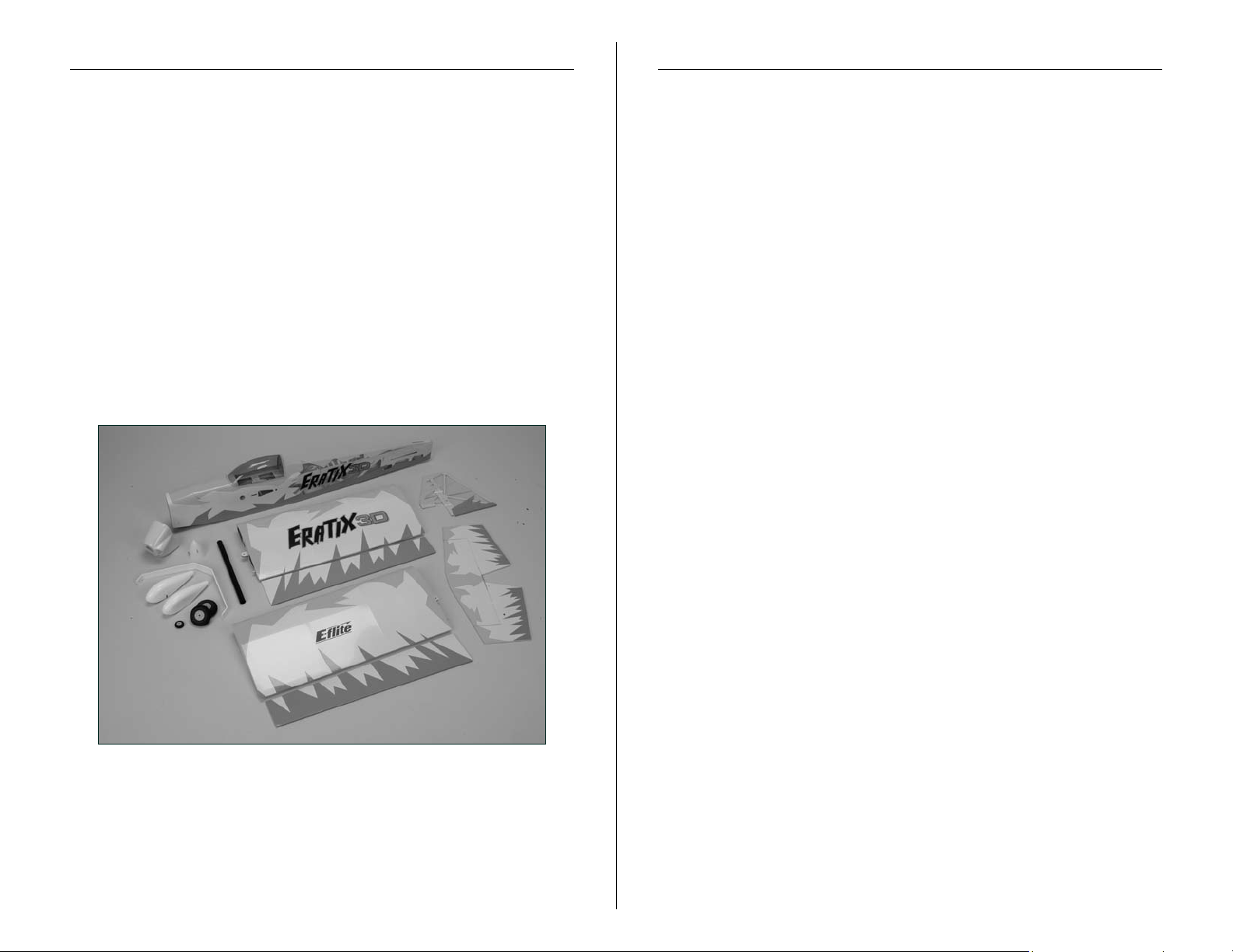
Contents of Kit/Parts Layout
Required Tools and Adhesives
Large Replacement Parts:
EFL4076 Wing Set w/Ailerons
EFL4077 Fuselage
EFL4078 Tail Set
EFL4080 Main Landing Gear
EFL4083 Fuse Hatch
EFL4085 Canopy
EFL4079 Cowling
EFL4081 Wheel Pants
EFL4084 Wing Tube
Small Replacement Parts
3
HAN305 Pro-Lite Wheels, 2
/
4
EFL4082 Pushrod Set
EFLA213 E-flite/JR/Horizon Decals
-inch (70mm)
Tools & Equipment
EFLA258 Screwdriver, #1 Phillips
EFLA257 Screwdriver, #0 Phillips
(Both included with EFLA250)
EFLA251 Hex Wrench:
3
/
32
-inch
(or included with EFLA250)
EFLA263 Nut Driver, 1/4-inch
Drill
Pen drill
Drill bit: 1/16-inch (1.5mm), 5/64-inch (2mm)
Masking tape
Felt-tipped pen
Hex wrench: 1.5mm
Needle-nose pliers
Medium grit sandpaper
Side cutters
T-pins
Paper towels
Hobby knife
Ruler
Square
String or dental floss
Pliers
7mm nut driver
Rotary tool
Adhesives
30-minute epoxy
Thin CA
Threadlock
3E-flite Eratix 3D 25e ARF Assembly Manual
Page 4

Required Radio Equipment
You will need a minimum 6-channel transmitter, receiver, and
four mini servos. You can choose to purchase a complete radio
system that includes all of these items or, if you are using an
existing transmitter, just purchase the other required equipment
separately.
Note: We recommend the crystal-free, interference-free
Spektrum™ DX7 2.4GHz DSM2™ 7-channel radio. The
complete system includes standard servos, which are not
required for the Eratix 3D 25e.
Purchase Separately
SPM6070 DSM2 7-Channel Receiver
Or
JRPR720 7-Channel ScanSelect
™
FM Receiver
JSP98010 JR SPORT™ 4.8V 700mAh Rx Pack
EXRA050 Expert Standard Switch
Notes Regarding Servos and ESC
WARNING: Depending on what speed control you are using,
if it is not capable of supporting four mini-size servos because
of current draw, the speed control may shut down due to high
heat.
Use of servos other than those we recommend may overload the
BEC of the recommended Electronic Speed Control (ESC). We
suggest the use of only the servos we recommend when utilizing
the recommended ESC’s BEC, or the use of a separate BEC (like
the UBEC) or receiver battery pack when using other servos.
Or
JRPR790 7-Channel ScanSelect PCM Receiver
JSP98030 12-inch (305mm) Servo Extension (2)
JRPSDS3421 DS3421 Digital MG Mini Servo (4)
HRC32225S HiTec 225MG
Note: When using our recommended E-flite 60A Pro
Brushless ESC with switching BEC you do not need a
separate receiver pack as long as you are using our
recommended servos.
Important Servo Note:
If you plan on flying your Eratix 3D 25e to its full
capabilities, we recommend only metal geared servos.
During 3D flight, the large control surfaces will exhibit
large flight loads on the servos. Plastic geared servos
failed during testing and are not recommended for use.
Important Information About Motor
Selection
The Eratix 3D 25e does not include a propeller. We are
recommending the Power 25 or Power 32 outrunner motors.
The motor systems listed will provide you with excellent
aerobatic power for sport and/or artistic aerobatic pilots.
Lightweight Sport Setup
EFLM4025A Power 25 BL Outrunner, 870Kv
EFLA1060 60A Pro Switching BEC Brushless ESC
THP42003S2PPL 4200mAh 3S2P 11.1V Li-Po, 13GA
APC14070E Electric Propeller, 14x7E
EFLC3005 Celectra™ 1- to 3-cell Li-Po Charger
EFLAEC303 EC3 Dev & Batt, Male/Female
This is a very good 3D/Aerobatic setup with
strong performance.
4 E-flite Eratix 3D 25e ARF Assembly Manual
Page 5
Recommended High Power
Optional Accessories
Precision Aerobatic Setup
EFLM4032A Power 32 BL Outrunner, 770Kv
EFLA1060 60A Pro Switching BEC Brushless ESC
APC13065E Electric Propeller, 13x6.5E
EFLAEC303 EC3 Dev & Batt, Male/Female
THP42004S2PPL 4200mAh 4S2P 14.8V Li-Po, 13GA
Or
THP38504SX 3850mAh 4S 14.8V Li-Po, 13 GA
This is a high power 3D/Aerobatic setup with very strong
aggressive performance.
Alternative Sport and
Precision Setups
EFLM4032A Power 32 BL Outrunner, 770Kv
THP42003S2PPL 4200mAh 3S2P 11.1V Li-Po, 13GA
APC14070E Electric Propeller, 14x7E
Or
EFLM4025A Power 25 BL Outrunner, 870Kv
THP42004S2PPL 4200mAh 4S2P 14.8V Li-Po, 13GA
APC11080E Electric Propeller, 11x8E
And
EFLA1060 60A Pro Switching BEC Brushless ESC
EFLAEC303 EC3 Dev & Batt, Male/Female
This is an alternative sport and precision aerobatic setup and
is a good option if you have some equipment and do not
want to purchase additional. Both options are very similar in
performance; you should expect better performance than our
lightweight sport setup and less performance than with our
recommended high power precision setup.
EFLA110 Power Meter
HAN172 Hangar 9
Rx Current Meter
JRPA215 Large Servo Arm (2)
®
Digital Servo and
Notes on Lithium Polymer Batteries
Lithium Polymer batteries are significantly more
volatile than alkaline or Ni-Cd/Ni-MH batteries used
in RC applications. All manufacturer’s instructions
and warnings must be followed closely. Mishandling
of Li-Po batteries can result in fire. Always follow the
manufacturer’s instructions when disposing of Lithium
Polymer batteries.
Warning
An RC aircraft is not a toy! If misused, it can cause serious
bodily harm and damage to property. Fly only in open areas,
preferably at AMA (Academy of Model Aeronautics) approved
flying sites, following all instructions included with your radio.
Keep loose items that can get entangled in the propeller away
from the prop, including loose clothing, or other objects such as
pencils and screwdrivers. Especially keep your hands away from
the propeller.
Warranty Period
Horizon Hobby, Inc., (Horizon) warranties that the Products
purchased (the “Product”) will be free from defects in materials
and workmanship at the date of purchase by the Purchaser.
5E-flite Eratix 3D 25e ARF Assembly Manual
Page 6

Limited Warranty
Damage Limits
(a) This warranty is limited to the original Purchaser
("Purchaser") and is not transferable. REPAIR OR REPLACEMENT
AS PROVIDED UNDER THIS WARRANTY IS THE EXCLUSIVE
REMEDY OF THE PURCHASER. This warranty covers only those
Products purchased from an authorized Horizon dealer. Third
party transactions are not covered by this warranty. Proof of
purchase is required for warranty claims. Further, Horizon
reserves the right to change or modify this warranty without
notice and disclaims all other warranties, express or implied.
(b) Limitations- HORIZON MAKES NO WARRANTY OR
REPRESENTATION, EXPRESS OR IMPLIED, ABOUT NONINFRINGEMENT, MERCHANTABILITY OR FITNESS FOR A
PARTICULAR PURPOSE OF THE PRODUCT. THE PURCHASER
ACKNOWLEDGES THAT THEY ALONE HAVE DETERMINED
THAT THE PRODUCT WILL SUITABLY MEET THE REQUIREMENTS
OF THE PURCHASER’S INTENDED USE.
(c) Purchaser Remedy- Horizon's sole obligation hereunder
shall be that Horizon will, at its option, (i) repair or (ii)
replace, any Product determined by Horizon to be defective.
In the event of a defect, these are the Purchaser's exclusive
remedies. Horizon reserves the right to inspect any and all
equipment involved in a warranty claim. Repair or replacement
decisions are at the sole discretion of Horizon. This warranty
does not cover cosmetic damage or damage due to acts of
God, accident, misuse, abuse, negligence, commercial use,
or modification of or to any part of the Product. This warranty
does not cover damage due to improper installation, operation,
maintenance, or attempted repair by anyone other than
Horizon. Return of any goods by Purchaser must be approved
in writing by Horizon before shipment.
HORIZON SHALL NOT BE LIABLE FOR SPECIAL, INDIRECT
OR CONSEQUENTIAL DAMAGES, LOSS OF PROFITS OR
PRODUCTION OR COMMERCIAL LOSS IN ANY WAY
CONNECTED WITH THE PRODUCT, WHETHER SUCH CLAIM IS
BASED IN CONTRACT, WARRANTY, NEGLIGENCE, OR STRICT
LIABILITY. Further, in no event shall the liability of Horizon
exceed the individual price of the Product on which liability
is asserted. As Horizon has no control over use, setup, final
assembly, modification or misuse, no liability shall be assumed
nor accepted for any resulting damage or injury. By the act of
use, setup or assembly, the user accepts all resulting liability.
If you as the Purchaser or user are not prepared to accept the
liability associated with the use of this Product, you are advised
to return this Product immediately in new and unused condition
to the place of purchase.
Law: These Terms are governed by Illinois law (without regard to
conflict of law principals).
Safety Precautions
This is a sophisticated hobby Product and not a toy. It must be
operated with caution and common sense and requires some
basic mechanical ability. Failure to operate this Product in a safe
and responsible manner could result in injury or damage to the
Product or other property. This Product is not intended for use
by children without direct adult supervision. The Product manual
contains instructions for safety, operation and maintenance. It is
essential to read and follow all the instructions and warnings in
the manual, prior to assembly, setup or use, in order to operate
correctly and avoid damage or injury.
6 E-flite Eratix 3D 25e ARF Assembly Manual
Page 7

Questions, Assistance, and Repairs
Non-Warranty Repairs
Your local hobby store and/or place of purchase cannot provide
warranty support or repair. Once assembly, setup or use of the
Product has been started, you must contact Horizon directly.
This will enable Horizon to better answer your questions and
service you in the event that you may need any assistance.
For questions or assistance, please direct your email to
productsupport@horizonhobby.com, or call 877.504.0233 toll
free to speak to a service technician.
Inspection or Repairs
If this Product needs to be inspected or repaired, please call for
a Return Merchandise Authorization (RMA). Pack the Product
securely using a shipping carton. Please note that original boxes
may be included, but are not designed to withstand the rigors
of shipping without additional protection. Ship via a carrier that
provides tracking and insurance for lost or damaged parcels, as
Horizon is not responsible for merchandise until it arrives and
is accepted at our facility. A Service Repair Request is available
at www.horizonhobby.com on the “Support” tab. If you do not
have internet access, please include a letter with your complete
name, street address, email address and phone number where
you can be reached during business days, your RMA number,
a list of the included items, method of payment for any nonwarranty expenses and a brief summary of the problem.
Your original sales receipt must also be included for warranty
consideration. Be sure your name, address, and RMA number
are clearly written on the outside of the shipping carton.
Warranty Inspection and Repairs
Should your repair not be covered by warranty the repair
will be completed and payment will be required without
notification or estimate of the expense unless the expense
exceeds 50% of the retail purchase cost. By submitting the item
for repair you are agreeing to payment of the repair without
notification. Repair estimates are available upon request. You
must include this request with your repair. Non-warranty repair
estimates will be billed a minimum of ½ hour of labor. In
addition you will be billed for return freight. Please advise us
of your preferred method of payment. Horizon accepts money
orders and cashiers checks, as well as Visa, MasterCard,
American Express, and Discover cards. If you choose to pay
by credit card, please include your credit card number and
expiration date. Any repair left unpaid or unclaimed after 90
days will be considered abandoned and will be disposed of
accordingly.
on electronics and model engines.
Electronics and engines requiring inspection or repair should be
shipped to the following address:
All other Products requiring warranty inspection or repair should
be shipped to the following address:
Please note: non-warranty repair is only available
Horizon Service Center
4105 Fieldstone Road
Champaign, Illinois 61822
Horizon Product Support
4105 Fieldstone Road
Champaign, Illinois 61822
To receive warranty service, you must include your original
sales receipt verifying the proof-of-purchase date. Provided
warranty conditions have been met, your Product will be
repaired or replaced free of charge. Repair or replacement
decisions are at the sole discretion of Horizon Hobby.
Please call 877-504-0233 with any questions or concerns
regarding this product or warranty.
7E-flite Eratix 3D 25e ARF Assembly Manual
Page 8

Safety, Precautions, and Warnings
Instructions for Disposal of WEEE by
As the user of this product, you are solely responsible for
operating it in a manner that does not endanger yourself
and others or result in damage to the product or the property
of others.
Carefully follow the directions and warnings for this and any
optional support equipment (chargers, rechargeable battery
packs, etc.) that you use.
This model is controlled by a radio signal that is subject to
interference from many sources outside your control. This
interference can cause momentary loss of control so it is
necessary to always keep a safe distance in all directions
around your model, as this margin will help to avoid collisions
or injury.
• Always operate your model in an open area away from cars,
traffic, or people.
• Avoid operating your model in the street where injury or
damage can occur.
• Never operate the model out into the street or populated
areas for any reason.
Users in the European Union
This product must not be disposed of with other waste. Instead,
it is the user’s responsibility to dispose of their waste equipment
by handing it over to a designated collection point for the
recycling of waste electrical and electronic equipment. The
separate collection and recycling of your waste equipment at
the time of disposal will help to conserve natural resources and
ensure that it is recycled in a manner that protects human health
and the environment. For more information about where you
can drop off your waste equipment for recycling, please contact
your local city office, your household waste disposal service or
where you purchased the product.
• Never operate your model with low transmitter batteries.
• Carefully follow the directions and warnings for this and any
optional support equipment (chargers, rechargeable battery
packs, etc.) that you use.
• Keep all chemicals, small parts and anything electrical out of
the reach of children.
• Moisture causes damage to electronics. Avoid water exposure
to all equipment not specifically designed and protected for
this purpose.
8 E-flite Eratix 3D 25e ARF Assembly Manual
Page 9
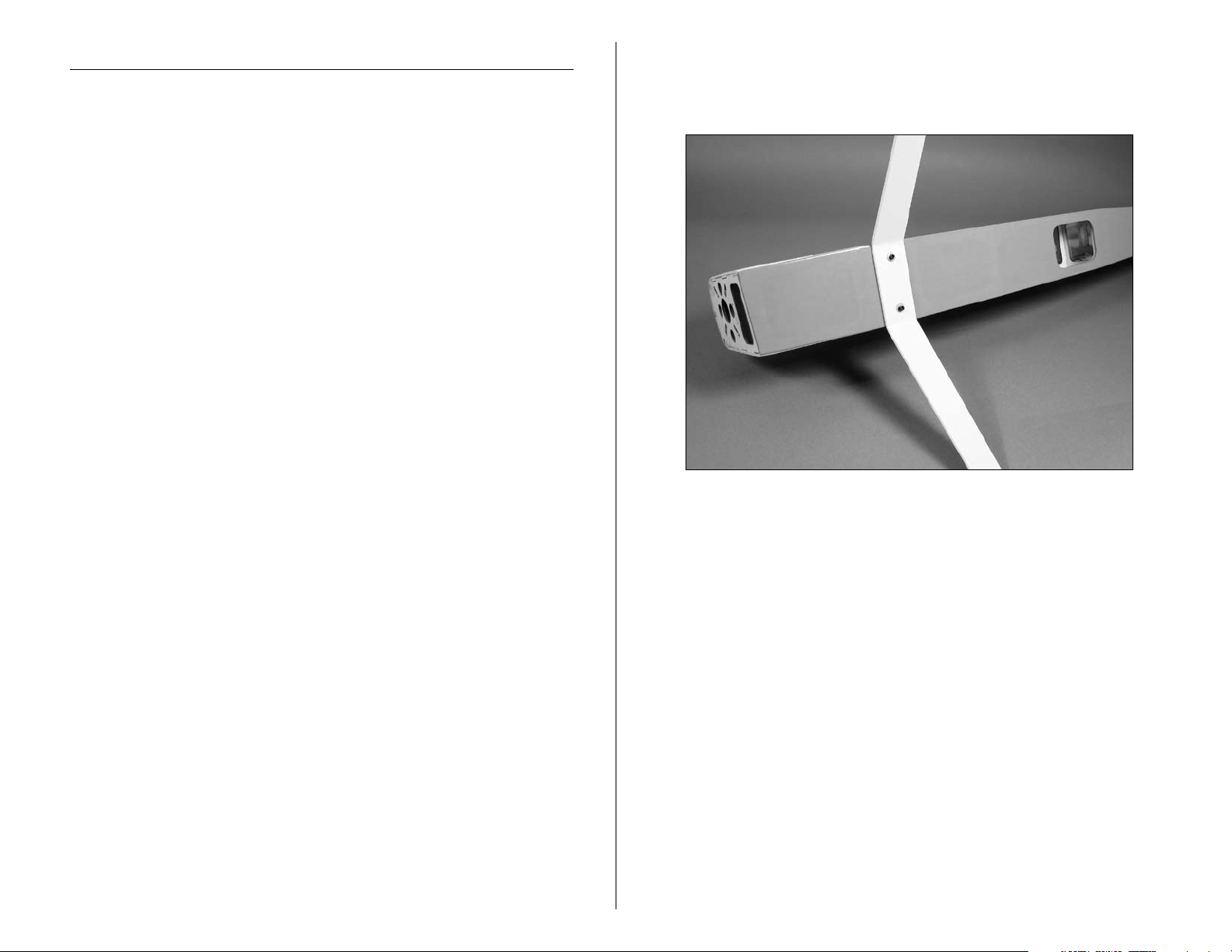
Landing Gear Installation
Required Parts
• Fuselage
• Main landing gear
• Wheel pant (left & right)
3
• 2
/
-inch (70mm) wheel (2)
4
• 4-40 x 1/2-inch socket head screw (2)
• #4 washers (6)
• 4mm locknut (4)
• 4mm x 35mm machine screw (2)
• 2mm x 8mm wood screws (4)
Required Tools and Adhesives
• Phillips screwdriver (small)
• Needle-nose pliers
• Nut driver: 7mm
• Hex wrench:
3
/
-inch
32
1. Place the landing gear onto the bottom of the fuselage.
Attach with two 4-40 x 1/2-inch socket head screws and
two #4 washers.
9E-flite Eratix 3D 25e ARF Assembly Manual
Page 10
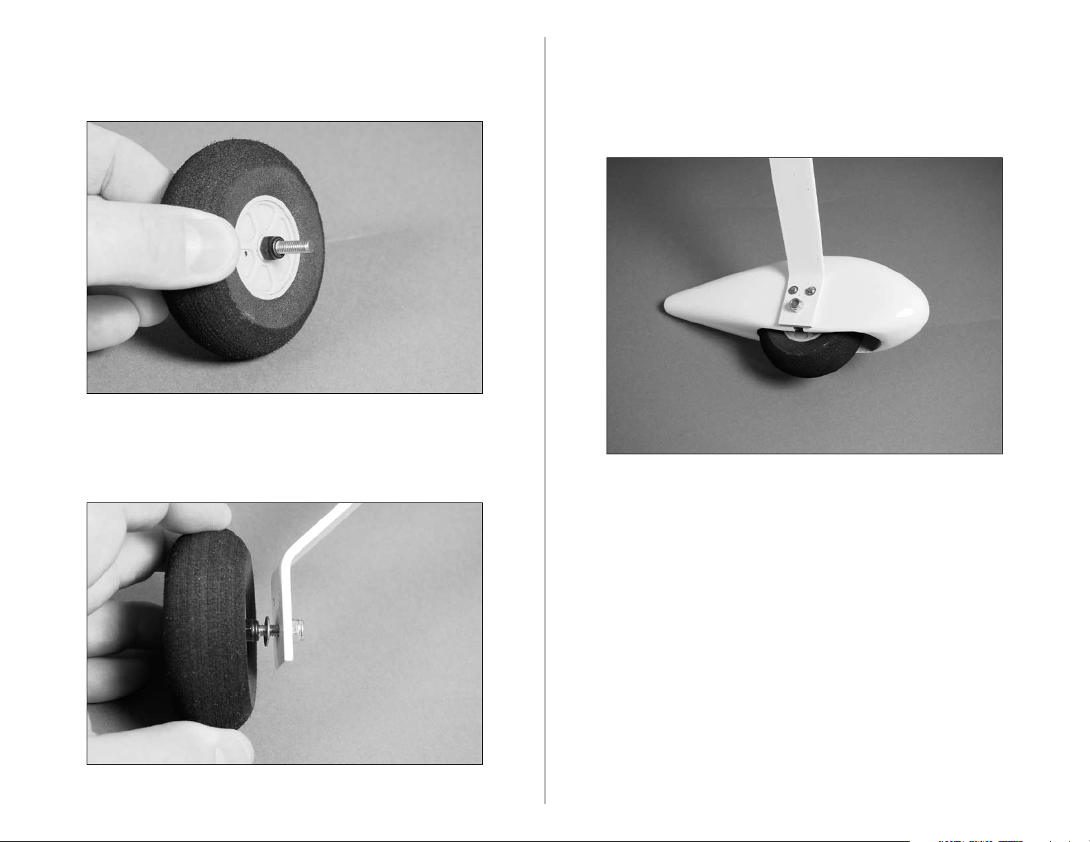
2. Slide the 4mm x 35mm machine screw through one of
3
2
/
the
-inch wheels. Secure a 4mm lock nut against the
4
wheel. Make sure the wheel still spins freely.
3. Attach the wheel to the landing gear using a
4mm washer and a 4mm lock nut. Leave the nut
loose at this time.
4. Slide the wheel pant over the wheel. The 4mm washer
will be inside the wheel pant. Use two 2mm x 8mm sheet
metal screws threaded into the pre-drilled holes to attach
the wheel pant to the landing gear. Tighten the 4mm lock
nut using a 7mm nut driver to complete the assembly.
5. Repeat Steps 2 through 4 for the remaining wheel
and wheel pant.
10 E-flite Eratix 3D 25e ARF Assembly Manual
Page 11

Motor Installation
Required Parts
• Fuselage assembly • 4-40 blind nut (4)
• Hook and loop strap (2)
• Cowling • 2
• Propeller • Brushless ESC
• 4-40 x 3/8-inch socket head screws
• Hook and loop tape, 3-inch (76mm) (2)
• 2mm x 10mm sheet metal screw (4)
Required Tools and Adhesives
• Hex wrench: 3/32-inch
• Drill • Phillips screwdriver #0
• Drill bit: 1/16 in (1.5mm)
Note: The firewall incorporates our new adjustable
mount system, enabling the modeler to install a variety of
outrunner motors.
1. Remove the hatch from the fuselage by lifting up at the
front of the hatch. The hatch is held at the front using a
magnet, and the rear using dowels.
1
/2-inch (64mm) spinner
2. Attach the mount to the motor using the hardware
provided with the motor.
3. Use four 4-40 x 3/8-inch socket head screws to secure
the motor to the firewall. The blind nuts installed behind
the firewall can be moved to allow for the mounting of
various sizes of motors.
11E-flite Eratix 3D 25e ARF Assembly Manual
Page 12

3. Plug the motor into the speed control. Use hook and
loop tape to secure the speed control inside the fuselage
out of the way of the battery.
4. Use the two hook and loop straps included with your
plane to secure the battery inside the fuselage.
Note: If the battery slides forward or backward, use hook
and loop tape on the battery and inside the fuselage to
prevent the battery from moving.
Note: When using our recommended E-flite 60A Pro
Brushless ESC with switching BEC you do not need a
separate receiver pack as long as you are using our
recommended servos.
If your ESC is not capable of supporting the current draw
of four mini-size servos the speed control may shut down
due to high heat.
5. Now is a good time to test the operation of the
motor. Use your radio system and plug the speed
control into the receiver. With the battery plugged
in, use the throttle stick to operate the motor. Check
that the motor operates properly, and that it rotates
counterclockwise when viewed from the front of the
plane. Follow the instructions provided with the speed
control to correct for operational problems.
In order to provide the most reliable product, E-flite
recommends the use of a separate BEC (like the Ultimate
BEC), or receiver pack and switch to ensure trouble-free
operation as follows:
Use the battery and switch harness to power the receiver
and servos after disabling the BEC on the ESC (by
following the instructions included with the ESC).
12 E-flite Eratix 3D 25e ARF Assembly Manual
Page 13

7. Slide the cowling onto the fuselage. Use the propeller
adapter to attach the propeller and spinner backplate
temporarily onto the motor. Position the cowling so it
lines up with the spinner backplate, and has a small gap
between the spinner backplate and cowling.
9. Secure the cowling using the four 2mm x 6mm sheet
metal screws. There are two screws on each side of the
cowl as shown. Complete the cowling installation by
attaching the spinner cone using the two screws provided
with the spinner.
8. With the cowl aligned with the spinner, use a drill and
1/16-inch (1.5mm) drill bit to drill through the cowl and
into the fuselage using the holes in the cowling.
13E-flite Eratix 3D 25e ARF Assembly Manual
Page 14

Aileron Installation
Required Parts
• Wing • Receiver
• Servo w/hardware (2) • Long servo arm (2)
• CA hinge (8)
• Clevis (2) • Clevis retainer (2)
• Nylon control horn (2) • 3mm x 30mm machine screw (2)
• Control horn standoff (2) • Control horn washer (2)
7
•
2
/
-inch (73mm) pushrod wire (2)
8
• Pushrod wire connector (2)
Required Tools and Adhesives
• Rotary tool • Drill bit: 1/16-inch (1.5mm)
• T-pins • Thin CA
• Felt-tipped pen • Pen drill
• Threadlock • Side cutters
• #1 Phillips screwdriver
1. Locate four CA hinges. Place a T-pin in the center of
each hinge.
2. Use a rotary tool and a 1/16-inch (1.5mm) drill bit
to drill a hole in the center of each hinge slot of both the
aileron and wing. This provides a tunnel for the CA to
wick into, penetrating the hinge.
Hint: You can prepare the rudder, fin, elevator and
stabilizer at this time as well.
3. Slide the four hinges into the slots in the aileron.
14 E-flite Eratix 3D 25e ARF Assembly Manual
Page 15

4. Slide the aileron into position on the wing. The
T-pins installed in the hinges will help in keeping
equal amounts in the wing and aileron.
5. Align the aileron with the wing tip. Apply a few drops
onto each hinge. Make sure to apply the CA on both the
top and bottom of the hinge.
6. Gently pull the aileron from the wing once the CA has
fully cured. This is to verify the hinges are glued securely.
Important: Do not use accelerator on the hinges. The CA
must be allowed to soak in and penetrate the hinge.
Note: Placing a #11 hobby blade between the aileron
leading edge and wing trailing edge to position the
aileron will result in a nice free-moving hinge for 3D
throws without any binding.
15E-flite Eratix 3D 25e ARF Assembly Manual
Page 16

7. Flex the aileron through its range of motion a few
times to break in the hinges.
8. Repeat Steps 1 through 7 to complete the
aileron installation.
9. Place the servo into the opening in the wing. Use
a felt-tipped pen to mark the locations for the servo
mounting screws.
16 E-flite Eratix 3D 25e ARF Assembly Manual
Page 17

10. Use a pen drill and 1/16-inch (1.5mm) drill bit to
drill the four locations for the servo mounting screws.
11. Apply a few drops of thin CA to each of the four
holes. This will harden the underlying wood and help
in preventing the screws from pulling out.
12. Secure the servo in the wing using the screws
provided with the servo. Note the servo horn faces
towards the aileron.
17E-flite Eratix 3D 25e ARF Assembly Manual
Page 18

13. Use a hobby knife to pierce the covering for the
3mm x 30mm machine screw. Slide the screw into the
hole from the top of the wing. Slide a control horn
washer onto the screw, then thread the control horn
standoff onto the screw. Use a #1 Phillips screwdriver to
tighten the assembly.
14. Thread the nylon control horn onto the control
horn screw until the top of the horn is flush with the
top of the screw.
15. Slide a clevis retainer onto a nylon clevis. Thread the
7
2
/
clevis onto the
-inch (73mm) pushrod wire. Attach
8
the clevis to the control horn and slide the clevis retainer
over the forks of the clevis to secure it to the control horn.
Note: Use threadlock on the control horn screw to
prevent it from vibrating loose.
18 E-flite Eratix 3D 25e ARF Assembly Manual
Page 19

16. Use a pushrod wire connector to secure the wire to
the servo arm. Trim any excess wire using side cutters.
17. Repeat Steps 9 through 16 to complete the
aileron servo installation.
Wing Installation
Required Parts
•
Fuselage • Wing (right and left)
• Wing tube
1
/
• 4-40 x
-inch machine screw (2)
2
Required Tools and Adhesives
• Hex wrench: 3/32-inch
1. Slide the wing tube into a wing panel.
•#4 washer (2)
19E-flite Eratix 3D 25e ARF Assembly Manual
Page 20

2. Remove the hatch from the fuselage. Slide the wing
panel with tube into position on the fuselage.
3. Slide the remaining wing panel into position. Secure
1
/
the panels using 4-40 x
-inch machine screws with #4
2
washers (silver) using a 3/32-inch hex wrench.
Stabilizer and Elevator
Required Parts
• Fuselage w/wing installed
• Stabilizer • Elevator
• CA hinge (4) • Elevator joiner wire
Required Tools and Adhesives
• Hobby knife • Felt-tipped pen
• Ruler • T-pins
• Thin CA • Sandpaper
• 30-minute epoxy
1. Position the stabilizer into the slot in the aft end
of the fuselage. Check that the stabilizer is centered
in the fuselage.
4. Repeat Steps 2 and 3 for the remaining wing panel.
20 E-flite Eratix 3D 25e ARF Assembly Manual
Page 21

2. Measure from the stab tip to the wing tip. Adjust the
AA
A=A
Wing and stabilizer
parallel
stab until the measurements are equal.
3. View the airframe from the rear and make sure the
wing and stab are parallel. If not, lightly sand the stab
saddle until they are.
4. Double-check the adjustments from Steps 1 through 3.
Use a felt-tipped pen to trace the outline of the fuselage
onto the top and bottom of the stabilizer.
21E-flite Eratix 3D 25e ARF Assembly Manual
Page 22

5. Use a sharp hobby knife to cut the covering slightly
inside the lines drawn. Be very careful not to cut into the
underlying wood, as this will weaken the stab and cause
it to fail in flight.
Note: You can use a soldering iron instead of a knife.
This will eliminate the chances of cutting into the wood.
6. Slide the elevator jointer into position, then
the stabilizer.
7 . Check the alignment and make sure everything lines
up. Wick thin CA into the joint between the fuselage and
stabilizer. Make sure to glue both top and bottom. Do
not use accelerator— to allow the CA to wick in the joint,
providing the best bond possible.
22 E-flite Eratix 3D 25e ARF Assembly Manual
Page 23

8. Prepare two CA hinges by placing a T-pin in the
center of each hinge. Test fit the elevator against the
stabilizer. Make sure the joiner wire fits into the elevator
as well.
9. Rougher the joiner wire using medium grit sandpaper.
Apply 30-minute epoxy to the joiner wire and in the hole
in the elevator as well.
10. Follow the same procedure for hinging the ailerons to
hinge the stabilizer/elevator.
11. Repeat Steps 8 through 10 for the remaining
elevator.
23E-flite Eratix 3D 25e ARF Assembly Manual
Page 24

Rudder and Fin
Required Parts
•
Fuselage • Rudder
•
Fin • CA hinge (3)
• Tail wheel assembly • Tailwheel
• Wheel collar w/setscrew
Required Tools and Adhesives
• Hobby knife • Thin CA
• 30-minute epoxy • Medium grit sandpaper
• Hex wrench: 1.5mm
1. Roughen the tail wheel assembly using medium grit
sandpaper. Use 30-minute epoxy to glue the tail wheel
assembly into the fuselage.
2. Hinge the rudder and fin, using the same process
as described in Aileron Hinging. Use three hinges for
this process. Make sure to install the tail wheel into the
rudder as well, gluing it with 30-minute epoxy.
3. Install the tail wheel using the wheel collar
and setscrew. Use a 1.5mm hex wrench to tighten
the setscrew.
24 E-flite Eratix 3D 25e ARF Assembly Manual
Page 25

Rudder and Elevator Servos
Required Parts
• Fuselage
• Long servo arm (2) • Servo (2)
• Clevis (2) • Clevis retainer (2)
• Nylon control horn (2) • 3mm x 30mm machine screw (2)
• Control horn standoff (2) • Control horn washer (2)
• 4-inch (102mm) pushrod wire
1
• 5
/
-inch (140mm) pushrod wire
2
• 12-inch (305mm) servo extension (2)
• Pushrod wire connector (2)
Required Tools and Adhesives
• Phillips screwdriver (small) • Hobby knife
• 30-minute epoxy • Threadlock
• String or dental floss
1. Secure a 12-inch (305mm) servo extension to the
servo. Mount the elevator servo using the hardware
provided with the servo.
2. Attach the control horn in position on the rudder
and elevator using the same technique as the aileron
control horns.
Note: Use threadlock on the control horn screw to
prevent it from vibrating loose.
Note: Use string or dental floss to secure the servo lead
to the servo extension so they don't become unplugged
during flight.
25E-flite Eratix 3D 25e ARF Assembly Manual
Page 26

4. Assemble the elevator linkage using the 4-inch
(102mm) pushrod wire. Attach the linkage to a long
servo arm with a pushrod connector.
5. Repeat Steps 1 through 4 for the rudder servo and
1
5
/
linkage using the
-inch (140mm) pushrod wire.
2
26 E-flite Eratix 3D 25e ARF Assembly Manual
Page 27

6. Plug the elevator servo, rudder servo and ESC into the
receiver. Mount the receiver to the inside of the fuselage
using hook and loop material. Route the antenna wire
through the bottom of the fuselage to the rear, or as
directed by your radio instruction manual.
Note: Do not cut or change the length of the antenna
wire, as this will reduce the range of your radio system.
Control Throws
1. Turn on the transmitter and receiver of your aircraft.
Check the movement of the rudder using the transmitter.
When the stick is moved right, the rudder should also
move right. Reverse the direction of the servo at the
transmitter if necessary.
2. Check the movement of the ailerons using the
transmitter. When the stick is moved right, the right
aileron will move up and the left aileron will move
down. Reverse the direction of the servo at the transmitter
if necessary.
3. Check the movement of the elevator with the radio
system. Moving the elevator stick down will make the
airplane elevator move up.
4. Use a throw gauge to adjust the throw of the elevator,
ailerons and rudder. Adjust the position of the pushrod
at the control horn, or the travel/endpoint adjustments
of your computer transmitter, to achieve the following
measurements when moving the sticks to their endpoints.
27E-flite Eratix 3D 25e ARF Assembly Manual
Page 28

The control throw measurements are taken at the widest
point on the surface.
Low Rate High Rate
Ailerons:
Up 1-inch (25mm) 3-inch (76mm)
Down 1-inch (25mm) 3-inch (76mm)
Elevator:
1
/
Up 1-inch (25mm) 3
Down 1-inch (25mm) 3
-inch (90mm)
2
1
/
-inch (90mm)
2
Rudder:
1
/
Right 2-inch (51mm) 4
Left 2-inch (51mm) 4
-inch (114mm)
2
1
/
-inch (114mm)
2
These are general guidelines measured from our own
flight tests. You can experiment with higher rates to match
your preferred style of flying.
Center of Gravity
An important part of preparing the aircraft for flight is properly
balancing the model.
Caution: Do not inadvertently skip this step!
The recommended Center of Gravity (CG) location for the
1
/
Eratix 3D 25e is 3
inches (83mm) to 4 inches (102mm) back
4
measured from the center of the leading edge of the wing next
to the fuselage.
After your first flights, the Center of Gravity can be adjusted for
personal preference.
28 E-flite Eratix 3D 25e ARF Assembly Manual
Page 29

Range Test Your Radio
Preflight
1. Before each flying session, be sure to range check
your radio. This is accomplished by turning on your
transmitter with the antenna collapsed. Turn on the
receiver in your airplane. With your airplane on the
ground and the engine running, you should be able to
walk 30 paces (approximately 100 feet) away from your
airplane and still have complete control of all functions.
If not, don’t attempt to fly! Have your radio equipment checked
out by the manufacturer.
2. Double-check that all controls (aileron,elevator, rudder
and throttle) move in the correct direction.
3. Be sure that your transmitter batteries are
fully charged, per the instructions included
with your radio.
Check Your Radio
Before going to the field, be sure that your batteries are fully
charged per the instructions included with your radio. Charge
both the transmitter and receiver pack for your airplane. Use
the recommended charger supplied with your particular radio
system, following the instructions provided with the radio. In
most cases, the radio should be charged the night before going
out flying.
Before each flying session, be sure to range check your radio.
See your radio manual for the recommended range and
instructions for your radio system. Each radio manufacturer
specifies different procedures for their radio systems. Next, start
the motor. With the model securely anchored, check the range
again. The range test should not be significantly affected. If it is,
don’t attempt to fly! Have your radio equipment checked out by
the manufacturer.
Note: Keep loose items that can get entangled in
the propeller away from the prop. These include
loose clothing, or other objects such as pencils and
screwdrivers. Especially keep your hands away from the
propeller.
Double-check that all controls (aileron, elevator, rudder and
throttle) move in the correct direction.
Check the radio installation and make sure all the control
surfaces are moving correctly (i.e. the correct direction and with
the recommended throws). Test run the motor and make sure
it transitions smoothly from off to full throttle and back. Also
ensure the engine is installed according to the manufacturer’s
instructions, and it will operate consistently.
Check all the control horns, servo horns, and clevises to make
sure they are secure and in good condition. Replace any items
that would be considered questionable. Failure of any of these
components in flight would mean the loss of your aircraft.
29E-flite Eratix 3D 25e ARF Assembly Manual
Page 30

Flying Your Eratix 3D 25e
Flying the Eratix 3D 25e is about as fun as it can get at the
field. A very light wing loading and extreme control throws
make for some exciting 3D flying. Verify that your CG is at the
correct location as per the manual and that you have your rates
set up to your liking. Verify all control throws are in the correct
direction and the motor spins in the correct direction as well.
Point the model into the wind and add some throttle trim until
the motor begins to turn. This will be your flight idle. Now,
apply power slowly. You will find the model will become
airborne very quickly and at a low speed. This model excels
at flying slow and easy as well as fast and extreme. Trim the
model for level flight at half throttle. Only use full throttle for
maneuvering. It is not recommended to fly this model fast or
at full throttle in level flight. Doing this can result in the flight
controls fluttering and a potential catastrophic failure of the
airframe.
You will find you can adjust the CG to your liking by moving the
battery pack fore or aft on the fuselage. Also keep the battery
on the fuselage mounted high (at least at wing centerline or
above) to help in hovering maneuvers and harriers.
To land the Eratix 3D 25e just reduce the throttle to idle and
feed in up elevator until the model settles into a slightly nose
high attitude. Gently fly the model down to the landing spot
with a final flair at touchdown. You will find the model will have
a very short roll out. We hope you enjoy the Eratix 3D 25e as
much as we do.
Happy landings.
30 E-flite Eratix 3D 25e ARF Assembly Manual
Page 31

2007 Official AMA National
Model Aircraft Safety Code
GENERAL
1) I will not fly my model aircraft in sanctioned events, air shows
or model flying demonstrations until it has been proven to be
airworthy by having been previously, successfully flight tested.
2) I will not fly my model higher than approximately 400 feet within 3
miles of an airport without notifying the airport operator. I will give
right-of-way and avoid flying in the proximity of full-scale aircraft.
Where necessary, an observer shall be utilized to supervise flying
to avoid having models fly in the proximity of full-scale aircraft.
3) Where established, I will abide by the safety rules for the flying
site I use, and I will not willfully or deliberately fly my models in a
careless, reckless and/or dangerous manner.
4) The maximum takeoff weight of a model is 55 pounds, except
models flown under Experimental Aircraft rules.
5) I will not fly my model unless it is identified with my name and
address or AMA number on or in the model. (This does not apply
to models while being flown indoors.)
6) I will not operate models with metal-bladed propellers or with
gaseous boosts, in which gases other than air enter their internal
combustion engine(s); nor will I operate models with extremely
hazardous fuels such as those containing tetranitromethane or
hydrazine.
RADIO CONTROL
1) I will have completed a successful radio equipment ground range
check before the first flight of a new or repaired model.
2) I will not fly my model aircraft in the presence of spectators until I
become a qualified flier, unless assisted by an experienced helper.
3) At all flying sites a straight or curved line(s) must be established
in front of which all flying takes place with the other side for
spectators. Only personnel involved with flying the aircraft are
allowed at or in front of the flight line. Intentional flying behind the
flight line is prohibited.
4) I will operate my model using only radio control frequencies
currently allowed by the Federal Communications Commission.
(Only properly licensed Amateurs are authorized to operate
equipment on Amateur Band frequencies.)
5) Flying sites separated by three miles or more are considered safe
from site-to-site interference, even when both sites use the same
frequencies. Any circumstances under three miles separation
require a frequency management arrangement, which may be
either an allocation of specific frequencies for each site or testing
to determine that freedom from interference exists. Allocation plans
or interference test reports shall be signed by the parties involved
and provided to AMA Headquarters.
Documents of agreement and reports may exist between (1) two
or more AMA Chartered Clubs, (2) AMA clubs and individual
AMA members not associated with AMA Clubs, or (3) two or
more individual AMA members.
6) For Combat, distance between combat engagement line
and spectator line will be 500 feet per cubic inch of engine
displacement. (Example: .40 engine = 200 feet.); electric motors
will be based on equivalent combustion engine size. Additional
safety requirements will be per the RC Combat section of the
current Competition Regulations.
7) At air shows or model flying demonstrations, a single straight line
must be established, one side of which is for flying, with the other
side for spectators.
8) With the exception of events flown under AMA Competition rules,
after launch, except for pilots or helpers being used, no powered
model may be flown closer than 25 feet to any person.
9) Under no circumstances may a pilot or other person touch a
powered model in flight.
31E-flite Eratix 3D 25e ARF Assembly Manual
Page 32

10344
© 2007 Horizon Hobby, Inc.
4105 Fieldstone Road
Champaign, Illinois 61822
(877) 504-0233
horizonhobby.com
E-fliteRC.com
 Loading...