

Page 1

Deuces Wild ARF
Assembly Manual
Specifications
Wingspan: 62 in (1570mm)
Length: 62.5 in (1580mm)
Wing Area: 740 sq in (47.7 sq dm)
Weight w/o Battery: 9.2–10.5 lb (4.2–4.7 kg)
Weight w/Battery: 7.75–8.5 lb (3.5–3.9 kg)
Page 2

Table of Contents
Introduction
Introduction ......................................................................... 2
Using the Manual ................................................................ 2
Contents of Kit/Parts Layout ................................................. 3
Recommended Radio Equipment .......................................... 3
Required Tools and Adhesives .............................................. 4
Notes Regarding Servos and ESC ........................................ 4
Brushless Outrunner Setup, Power 25 ................................... 4
Brushless Outrunner Setup, Power 32 ................................... 4
Optional Accessories ........................................................... 4
Covering Colors .................................................................. 4
Note on Lithium Polymer Batteries ........................................ 5
Warning ............................................................................. 5
Fuselage Radio Installation ................................................... 5
Tail Attachment.................................................................... 8
Rudder and Elevator linkage Installation ............................. 10
Aileron Servo Installation ................................................... 16
Flap Servo Installation ....................................................... 21
Fixed Gear Installation ....................................................... 26
Retract Gear Installation ..................................................... 31
Retract Servo Installation .................................................... 40
Aileron and Throttle Servo Extensions ................................. 46
Power 25 Motor Installation ............................................... 48
Power 32 Motor Installation ............................................... 49
Propeller and Spinner Installation ....................................... 52
Wing Installation ............................................................... 56
Canopy and Gear Door Installation .................................... 57
Center of Gravity and Nose Cone Installation ..................... 59
Control Throws .................................................................. 60
Range Test Your Radio ....................................................... 61
Preflight ............................................................................ 61
Flying Your Deuces Wild .................................................... 62
Safety, Precautions, and Warnings ..................................... 63
Warranty Information ........................................................ 63
Instructions for Disposal of WEEE by
Users in the European Union ................................... 65
2008 Official AMA National Model Aircraft Safety Code ... 66
The Deuces Wild 25e2 ARF is the first twin and the first sport
plane in the Platinum Series. It is easier to fly than most other
twins and exhibits gentle flight characteristics. Along with the
superior features that come with every E-flite Platinum Series
plane, the Deuces Wild is full of enhanced details. All flight
control surfaces are installed, pushrods are pre-bent and
ready for installation and it includes optional gear doors.
The Deuces Wild also comes with a unique wing design in
that it utilizes two Selig airfoils to give it excellent performance
at high and low speeds, while also giving the pilot gentle
stall characteristics. It was even designed with the unthinkable
in mind—the loss of an engine. In the event of an engine
loss, this aircraft is still easily flyable. The lightweight sturdy
frame is constructed of balsa and plywood and covered in
genuineHangar 9 UltraCote for added durability. The bolt-on
tail assembly and removable wing panels are designed for
quick building and easy storage.
Flight characteristics, aerobatic capabilities and amazing
details—any experienced modeler would bet on the
Deuces Wild.
Using the Manual
This manual is divided into sections to help make assembly
easier to understand, and to provide breaks between each
major section. In addition, check boxes have been placed next
to each step to keep track of each step completed. Steps with
a single circle () are performed once, while steps with two
circles ( ) indicate that the step will require repeating, such
as for a right or left wing panel, two servos, etc.
Remember to take your time and follow the directions.
2 E-flite Deuces Wild Assembly Manual
Page 3
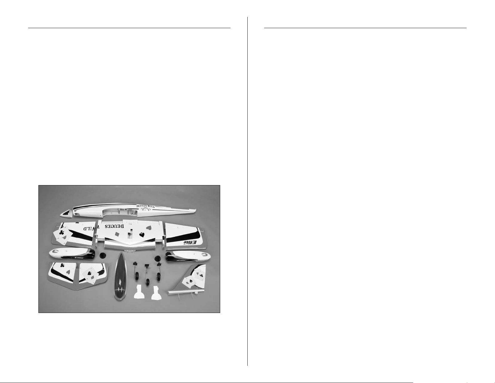
Contents of Kit/Parts Layout
Recommended Radio Equipment
Replacement Parts
EFL4551L Left Wing Panel
EFL4551C Center Wing Panel
EFL4551R Right Wing Panel
EFL4552 Fuselage
EFL4553 Tail Set
EFL4554L Left Nacelle
EFL4554R Right Nacelle
EFL4555 Landing Gear
EFL4556 Canopy
EFL4557 Pushrod Set
EFL4558 Spinner (Left Hand)
EFL4559 Spinner (Right Hand)
EFL4560 Wing Tube
EFL4561 Nose Cone
EFL4563 Strut Covers
You will need a minimum 6-channel transmitter, receiver, and
six or seven servos. You can choose to purchase a complete
radio system. If you are using an existing transmitter, just purchase
the other required equipment separately. We recommend the
crystalfree, interference-free Spektrum
™
DX6i 2.4GHz DSM®
6-channel system. If using your own transmitter, we recommend
the JR SPORT
™
standard servos.
If you own the Spektrum DX6i radio, just add the AR6200 DSM2
6-channel receiver and six JR SPORT ST47 Standard Servos.
Complete Radio System
SPM6600 DX6i DSM2 6CH system
SPM2710 DX7 DSM2 7CH system
Or Purchase Separately
SPMAR6200 AR6200 DSM2 6-Channel Full-Range
Receiver (for DX6i or DX7)
SPM6070 AR7000 DSM2 7-Channel Full Range
Receiver (for DX6i or DX7)
And
JSP20050 ST47 Standard Servo (6, 7 w/retracts)
JSP98020 6-inch Y-Harness (3)
EFLREX3L 3-inch Extension, Lightweight (4)
EFLREX9L 9-inch Extension, Lightweight (2)
EFLREX12L 12-inch Extension, Lightweight (2)
™
The Spektrum trademark is used with
permission of Bachmann Industries, Inc.
3E-flite Deuces Wild Assembly Manual
Page 4

Required Tools and Adhesives
Brushless Outrunner Setup, Power 25
Tools & Equipment
Felt-tipped pen Ball driver: 3/32-inch
Low-tack masking tape Mixing sticks
Paper towels Pin drill
Rubbing alcohol Mixing cups
Hobby knife (#11 blade) Pliers
Phillips screwdriver: #1, #2 Side cutters
Sandpaper Nut driver: 1/4-inch
Pencil Drill
Covering iron Flat screwdriver
Dental floss Scissors
Rotary tool w/high speed cutting bit
Drill bit: 1/16-inch (1.5mm), 5/64-inch (2mm),
3/32-inch (2.5mm), 3/16-inch (5mm)
Adhesives
Thin CA Medium CA
Threadlock 6-Minute Epoxy (HAN8000)
Canopy glue Silicone adhesive
Notes Regarding Servos and ESC
WARNING: Use of servos other than those we suggest may
overload the BEC of the recommended Electronic Speed Control
(ESC). Please use only the servos listed when utilizing the
recommended ESC’s BEC, or the use of a separate BEC (like the
UBEC) or receiver battery pack when using other servos.
EFLM4025A (2 req) Power 25 Brushless Outrunner Motor
870Kv
EFLA1060 (2 req) 60-Amp Pro Switch-Mode BEC
Brushless ESC
EFLB32003S (2 req) E-flite 3S 11.1V 3200mAh 20C Li-Po
APC12080E (1 req) 12x8 Electric Propeller
APC12080EP (1 req) 12x8 Electric Pusher Propeller
Brushless Outrunner Setup, Power 32
EFLM4032A (2 req) Power 32 Brushless Outrunner Motor,
770Kv
EFLA1060 (2 req) 60-Amp Pro Switch-Mode BEC
Brushless ESC
THP33004SXV (2 req) 4S 14.4V 3300mAh 25C Li-Po battery
APC13065E (1 req) 13x6.5 Electric Propeller
APC13065EP (1 req) 13x6.5 Electric Pusher Propeller
Optional Accessories
EFLA110 Power Meter
EFLC505 Intelligent 1- to 5-Cell Balancing Charger
EFL4562 Cockpit Kit, Deuces Wild ARF
EFL4565 Retracts, Deuces Wild ARF
DUB141 3/16-inch Wheel Collars (required for
retract installation)
Covering Colors
White HANU870
Flame Red HANU883
Black HANU874
4 E-flite Deuces Wild Assembly Manual
Page 5
Note on Lithium Polymer Batteries
Fuselage Radio Installation
Lithium Polymer batteries are significantly more
volatile than alkaline or Ni-Cd/Ni-MH batteries used
in RC applications. All manufacturer’s instructions
and warnings must be followed closely. Mishandling
of Li-Po batteries can result in fire. Always follow the
manufacturer’s instructions when disposing of Lithium
Polymer batteries.
Warning
An RC aircraft is not a toy! If misused, it can cause serious
bodily harm and damage to property. Fly only in open areas,
preferably at AMA (Academy of Model Aeronautics) approved
flying sites, following all instructions included with your radio.
Keep loose items that can get entangled in the propeller away
from the prop, including loose clothing, or other objects such as
pencils and screwdrivers. Especially keep your hands away from
the propeller.
Required Parts
Fuselage Servo w/hardware (3)
Hook and loop tape Receiver
3-inch (76mm) servo extension (3) (4 for optional retracts)
Required Tools and Adhesives
Pin drill Drill bit: 1/16-inch (1.5mm)
Thin CA Phillips screwdriver: #1
Pencil
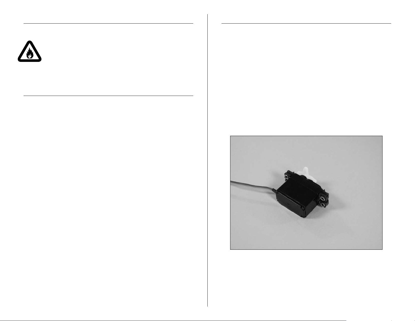
1. Install the servo grommets and brass eyelets into your
servos at this time. We feel it is easiest to prepare all the
servos to save time later. If so, you will need all 6 or 7
servos for this step.
5E-flite Deuces Wild Assembly Manual
Page 6
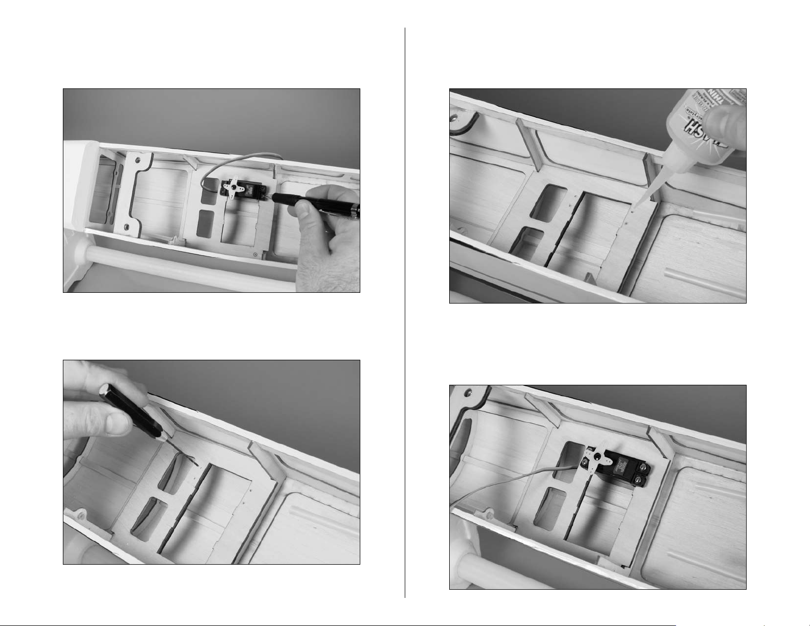
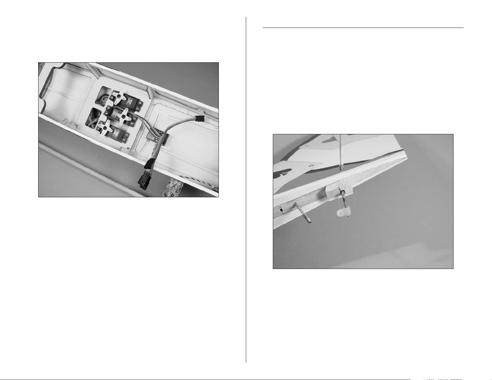
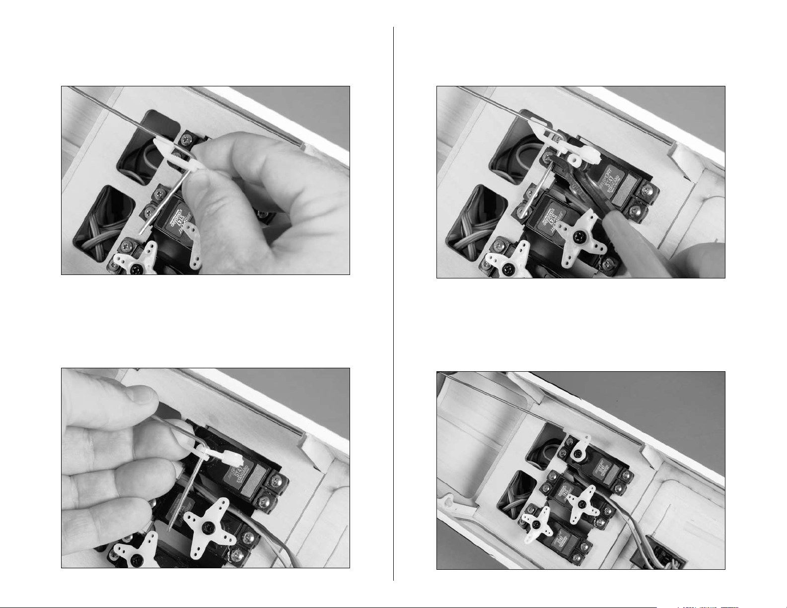
2. Position the elevator servo in the fuselage. Use a pencil
to transfer the locations for the servo mounting screws to
the servo tray.
3. Use a pin drill and 1/16-inch (1.5mm) drill bit to drill
the four holes for the servo mounting screws.
4. Apply 2–3 drops of thin CA into each of the holes to
harden the surrounding wood. This will provide a harder
surface for the screws to bite into when installed.
5. Secure the elevator servo in the fuselage using
the hardware provided with the servo and a #1
Phillips screwdriver.
6 E-flite Deuces Wild Assembly Manual
Page 7
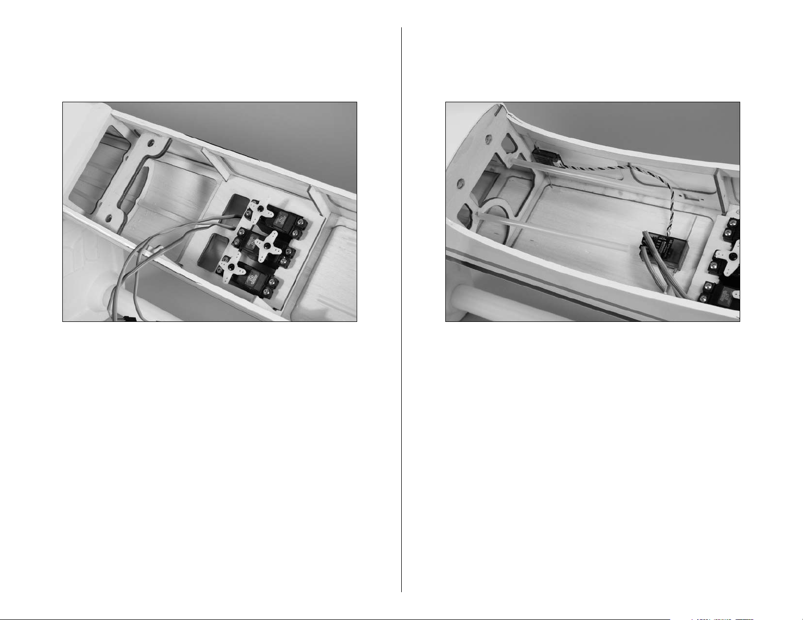
6. Repeat all of the previous steps to install the rudder
servo and steering servo in the fuselage. Note that the
steering servo is in the center location when installed.
Please note the orientation of the servos in the fuselage.
7. Use hook and loop tape to install the receiver into the
fuselage. When installing a remote receiver, place it as
far away from the main receiver as possible, aligning the
antennas perpendicular to those of the main receiver.
Note: If you are using a standard 72MHz receiver, an
antenna tube has been installed in the fuselage to route
the antenna wire to the rear of the fuselage. Never cut
the receiver antenna as this will greatly reduce the range
of your radio system.
7E-flite Deuces Wild Assembly Manual
Page 8
8. Plug a 3-inch (76mm) servo extension into the throttle,
aileron and flap ports on the receiver at this time. This
will make it easier to plug the leads that will be installed
in the wing later while assembling your aircraft.
Tail Attachment
Required Parts
Rudder/fin Elevator/stabilizer
Fuselage assembly Nylon control horn
4-40 lock nut (2) #4 washer (2)
Required Tools and Adhesives
Nut driver: 1/4-inch
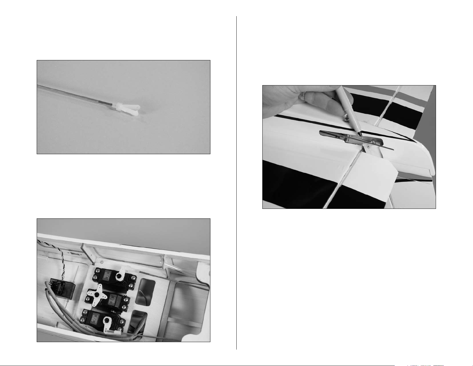
1. Thread the nylon control horn onto the rudder
torque rod. You will thread this on until the end of
the rod is flush with the nylon control horn.
Note: If you are installing retracts, plug a 3-inch (76mm)
extension into the port marked GEAR at this time as well.
8 E-flite Deuces Wild Assembly Manual
Page 9
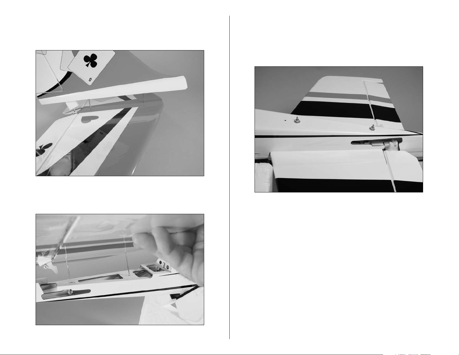
2. Slide the threaded rods from the fin into the holes in
the stabilizer. The fin will fit flush against the stabilizer
when installed.
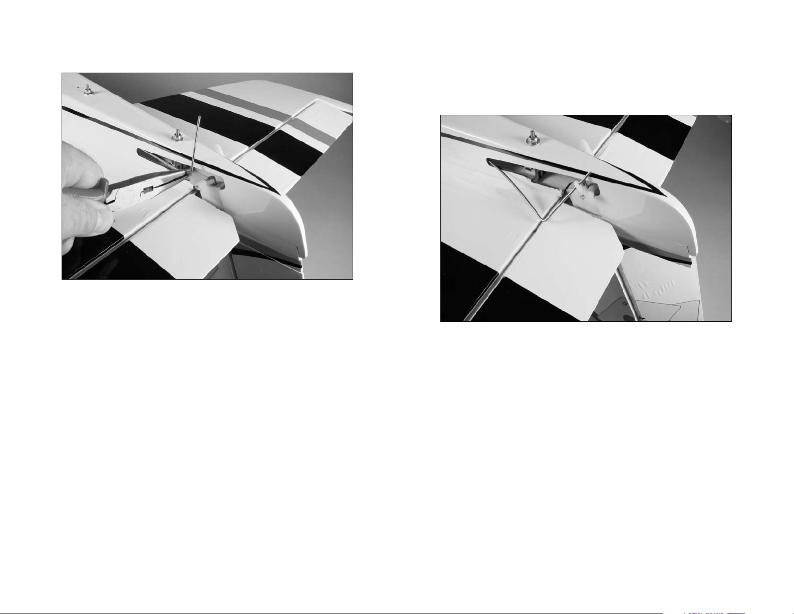
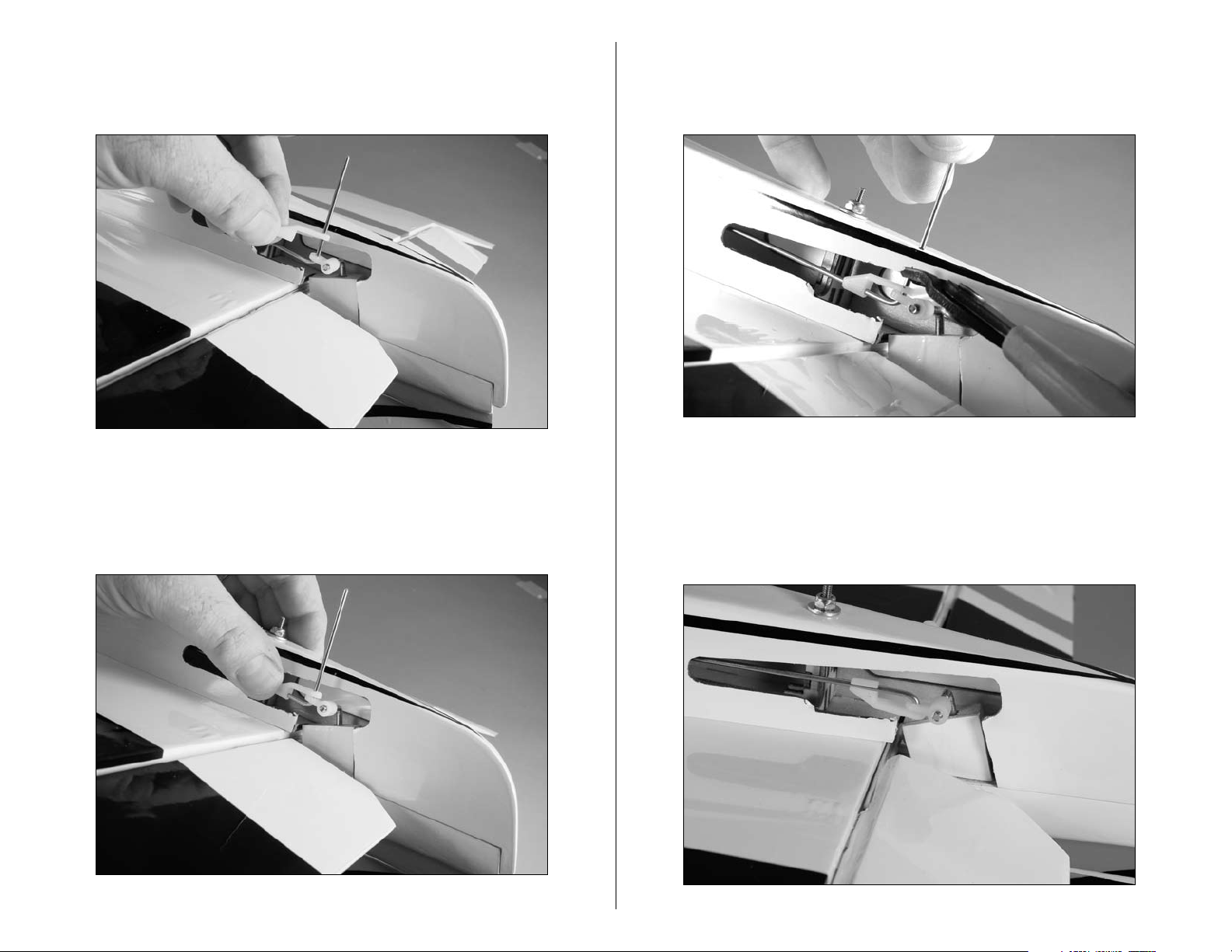
4. Using a 1/4-inch nut driver, secure the tail assembly
to the fuselage using two 4-40 lock nuts and two #4
washers. Do not over-tighten the nuts and damage the
fuselage. At this time the Rudder/Fin, Stab/Elevator, and
Fuselage should fit tight against each other.
3. Slide the threaded rods into the holes in the rear
of the fuselage.
9E-flite Deuces Wild Assembly Manual
Page 10
Rudder and Elevator linkage Installation
Required Parts
Fuselage assembly Nylon clevis (2)
Silicone clevis retainer (2) Nylon pushrod keeper (2)
3
29
/
-inch (755mm) pushrod wire (2)
4
Required Tools and Adhesives
Pin drill Drill bit: 5/64-inch (2mm)
Felt-tipped pen Pliers
Side cutters Phillips screwdriver: #1
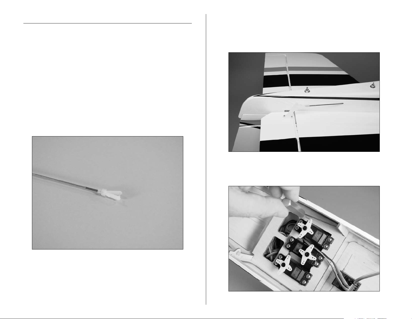
2. Slide the pushrod wire into the pre-installed pushrod
tube on the same side of the fuselage as the elevator
control horn. Attach the clevis to the elevator control horn
in the middle hole.
1. Thread a clevis onto one of the 29
pushrod wires. Make sure to slide a silicone clevis
retainer onto the clevis before threading it onto the
pushrod wire.
3
/
-inch (755mm)
4
3. Use a pin drill and 5/64-inch (2mm) drill bit to
enlarge the outer hole of the elevator servo horn.
10 E-flite Deuces Wild Assembly Manual
Page 11
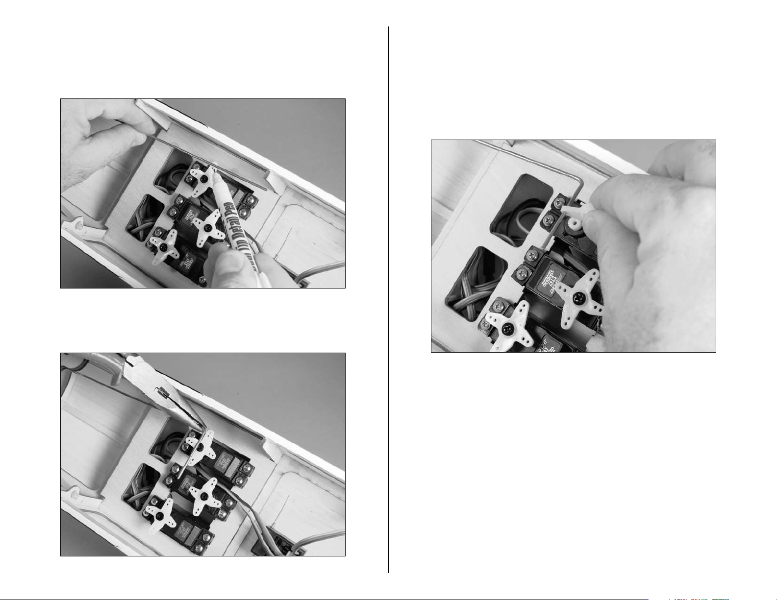
4. Center the elevator servo using the radio system. With
the elevator in the neutral position, use a felt-tipped pen
to mark the pushrod wire where it crosses the outside
hole on the servo horn.
5. Use pliers to bend the pushrod wire 90 degrees at the
mark made in the last step.
Note: Use side cutters to trim any arms that will interfere
with the operation of the rudder servo.
6. Using a #1 Phillips to remove the servo horn from
the servo. Slide the servo horn onto the pushrod wire
with the splined part of the horn that fits onto the servo
toward the bend.
11E-flite Deuces Wild Assembly Manual
Page 12
7. Next, slide the pushrod keeper onto the wire. Slide
the horn and keeper down so the horn it tight against
the bend.
9. Use side cutters to remove any excess wire that
extends beyond the connector. Leave a small amount of
wire to prevent the keeper from popping off accidentally.
8. The notch in the pushrod keeper will snap onto the
pushrod wire. This will keep the pushrod secure on the
servo horn. You may need to use pliers to apply enough
force to snap the pushrod keeper onto the wire.
12 E-flite Deuces Wild Assembly Manual
10. Rotate the pushrod wire 90 degrees so the servo
horn aligns with the servo output shaft. Use a #1 Phillips
screwdriver to reattach the servo horn to the elevator
servo at the center position.
Page 13
11. Thread a clevis onto one of the 29
3
/
-inch (755mm)
4
pushrod wires. Make sure to slide a silicone clevis
retainer onto the clevis before threading it onto the
pushrod wire.
12. Slide the wire into the rudder pushrod tube and
connect the clevis to the rudder servo horn. Plug a
Y-harness into the receiver rudder port of your receiver.
The rudder and nose wheel steering servo will plug into
this Y-harness.
Note: Use side cutters to trim any arms that will interfere
with the operation of the rudder servo.
13. Center the rudder servo using the radio system. With
the rudder in the center position, use a felt-tipped pen to
mark the pushrod where it crosses the hole in the rudder
control horn.
13E-flite Deuces Wild Assembly Manual
Page 14
14. Make a 90 degree bend in the pushrod wire at the
mark you made in Step 10.
15. Slide the pushrod wire through the hole in the rudder
control horn. You will need to rotate the horn so it can
be aligned with the pushrod for this step. Once the wire
has been inserted, you can rotate the control horn so it is
aligned with the pushrod wire.
14 E-flite Deuces Wild Assembly Manual
Page 15
16. Slide the pushrod keeper onto the wire. Position the
wire so the bend in the wire is snug against the control
horn as shown.
18. Use side cutters to remove any excess wire that
extends beyond the connector. Leave a small amount of
wire to prevent the keeper from popping off accidentally.
17. The notch in the pushrod keeper will snap onto the
pushrod wire. This will keep the pushrod secure. You
may need to use pliers to apply enough force to snap the
pushrod keeper onto the wire.
19. Remove the pushrod keeper and rotate the pushrod
180 degrees. Insert the pushrod into the nylon control
horn and reinstall the pushrod keeper. This is necessary
so the keeper doesn't bind against the fuselage during
the operation of the rudder.
15E-flite Deuces Wild Assembly Manual
Page 16
Aileron Servo Installation
Required Parts
Wing panel (right and left) Servo hatch (right and left)
Servo mounting block (4) Servo w/hardware (2)
Nylon clevis (2) Silicone clevis retainer (2)
Nylon pushrod keeper (2)
2mm x 10mm self-tapping screw (8)
4 1/4-inch (108mm) aileron pushrod wire (2)
Required Tools and Adhesives
Pencil 6-minute epoxy
Drill Pin drill
Phillips screwdriver: #1 Thin CA
Felt-tipped pen Pliers
Mixing cups Mixing sticks
Side cutters Sandpaper
Drill bit: 1/16-inch (1.5mm), 5/64-inch (2mm)
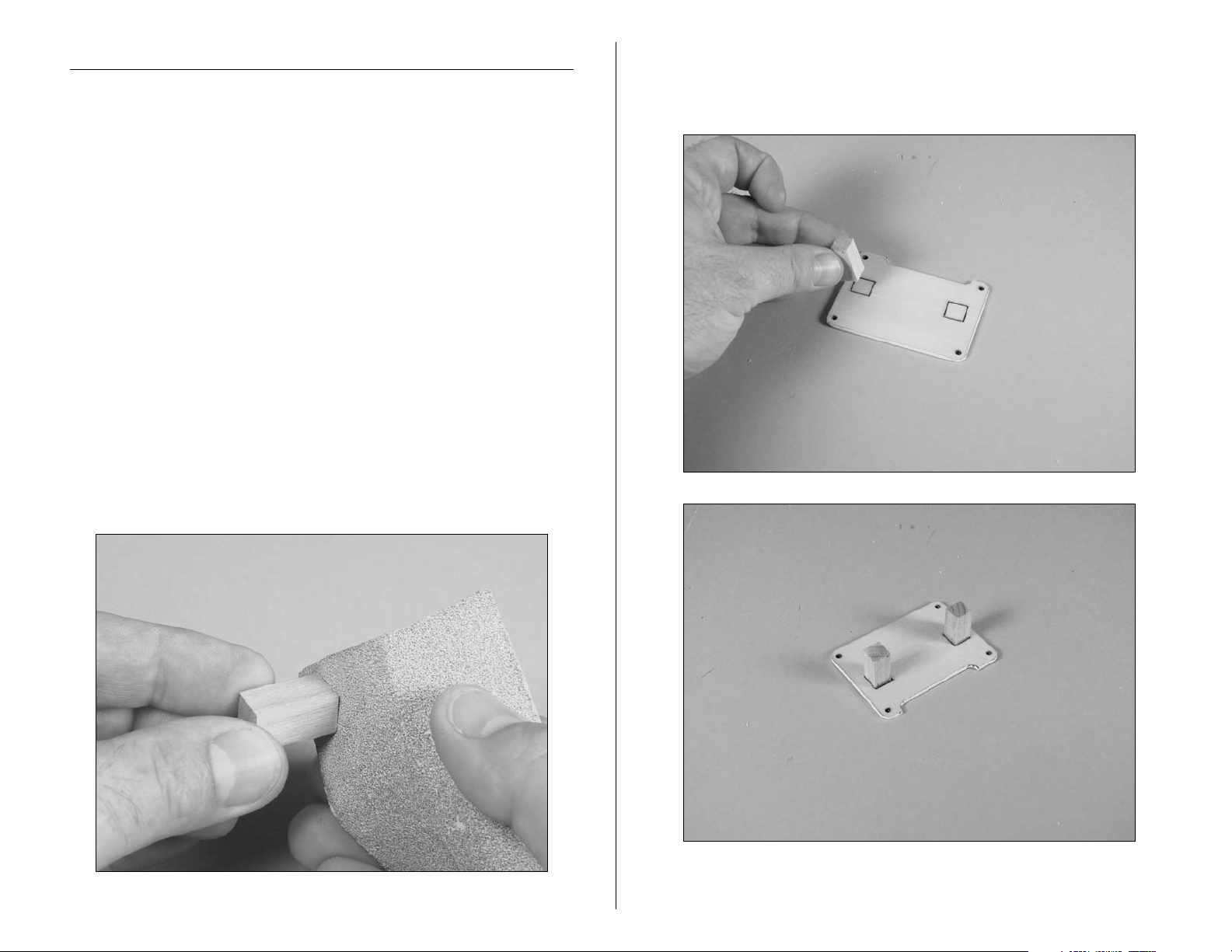
1. Use sandpaper to roughen the ends of the four servo
mounting blocks. Doing so will allow the epoxy applied
to them in the next step a better surface to adhere to.
2. Use 6-minute epoxy to secure the servo mounting
blocks on the servo hatch. The positions for the blocks
have been etched onto the hatch for your convenience.
16 E-flite Deuces Wild Assembly Manual
Page 17
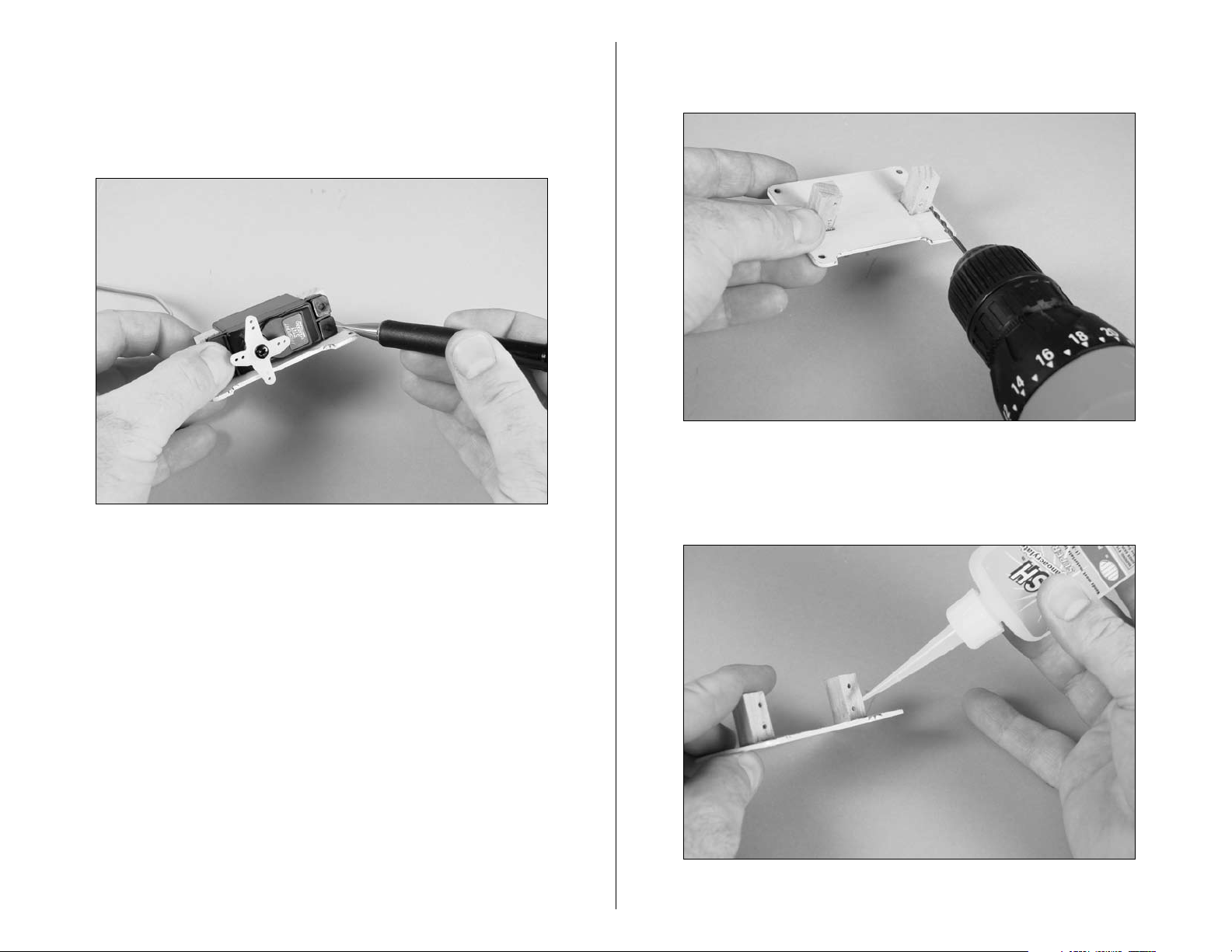
3. Position the servo between the blocks. Leave a small
gap between the servo and hatch to prevent the transfer
of vibration from the airframe into the servo. Use a pencil
to transfer the locations for the servo mounting screws
onto the servo mounting blocks.
4. Use a drill and 1/16-inch (1.5mm) drill bit to drill the
four holes for the servo mounting screws.
5. Apply 2–3 drops of thin CA into the holes to harden
the surrounding wood. This provides a hard surface for
the screws, making them more secure when installed.
17E-flite Deuces Wild Assembly Manual
Page 18
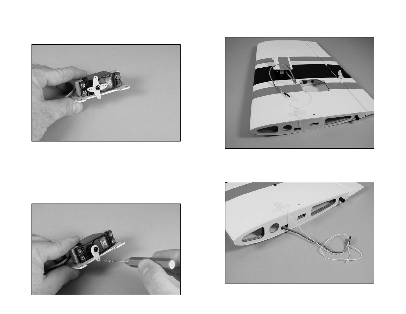
6. Attach the servo to the servo mounting blocks
using the screws provided with the servo and a
#1 Phillips screwdriver.
7. Remove the servo horn using a #1 Phillips screwdriver
and trim away any unused arms from the servo horn with
side cutters. Once complete reinstall the servo horn using
a #1 Phillips screwdriver. Use a pin drill and 5/64-inch
(2mm) drill bit to enlarge to outer hole in the remaining
servo arm as shown.
8. Tie the string that has been installed in the outer wing
panel to the servo lead.
9. Use the string to pull the servo lead through the wing
panel as shown.
18 E-flite Deuces Wild Assembly Manual
Page 19
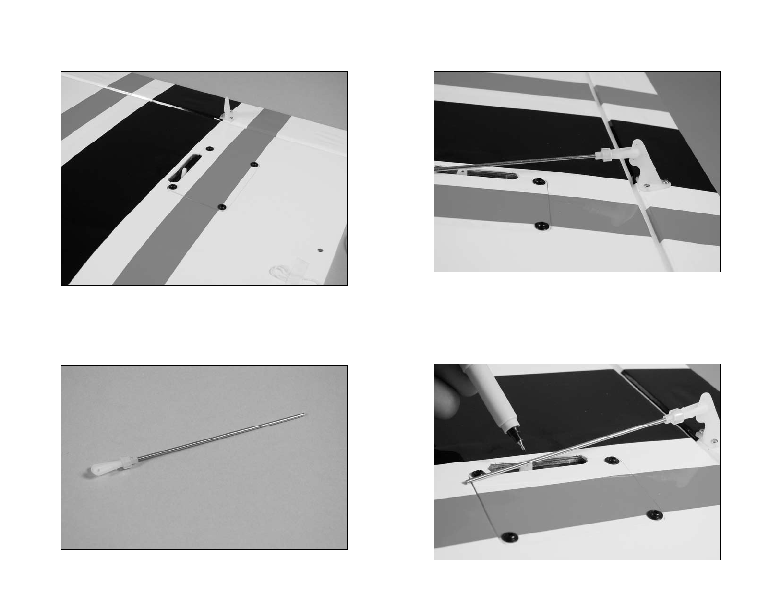
10. Secure the servo hatch to the wing using four 2mm x
10mm self tapping screws and a #1 Phillips screwdriver.
11. Slide a silicone clevis retainer onto a nylon clevis.
1
/
Thread the clevis onto the 4
-inch (108mm) aileron
4
pushrod wire.
12. Attach the clevis to the aileron control horn
center hole.
13. Use the radio system to center the aileron servo.
With the aileron in the center position, use a felt-tipped
pen to mark the pushrod where it crosses the hole in the
aileron servo arm.
19E-flite Deuces Wild Assembly Manual
Page 20
14. Use pliers to bend the pushrod 90-degrees at the
mark made in the previous step.
15. Slide the pushrod wire into the servo arm.
16. Secure the pushrod wire to the servo horn using
a nylon pushrod keeper. Use side cutters to remove
any excess pushrod wire that would interfere with the
operation of the aileron.
17. Repeat Steps 2 through 16 to install the remaining
aileron servo and linkage.
20 E-flite Deuces Wild Assembly Manual
Page 21
Flap Servo Installation
Required Parts
Wing center section Servo w/hardware
Brass pushrod connector Nylon connector backplate
Flap linkage Nylon clevis (2)
Silicone clevis retainer (2) 3mm x 5mm machine screw
Nylon control horn (2)
Required Tools and Adhesives
Felt-tipped pen Pin drill
Thin CA Side cutter
Phillips screwdriver: #1 Pliers
Threadlock
Drill bit: 1/16-inch (1.5mm), 5/64-inch (2mm)
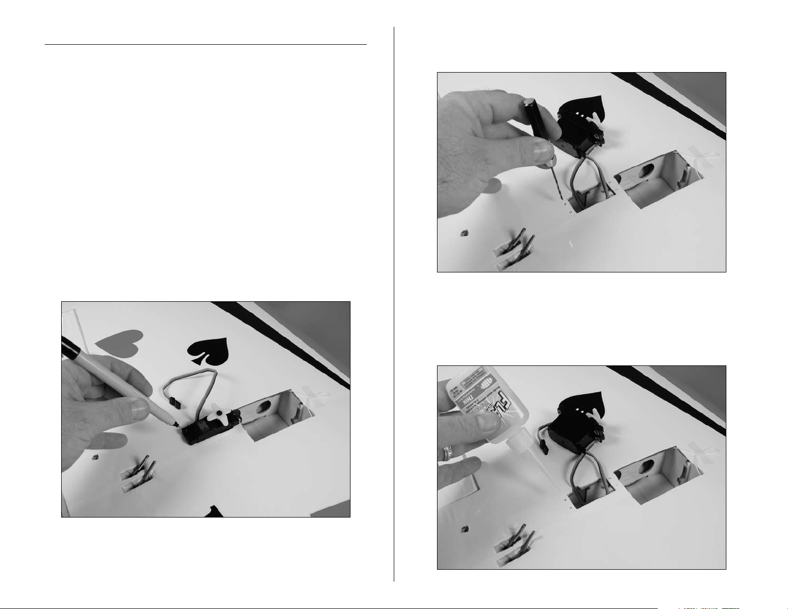
1. Position the flap servo into the wing. Use a felt-tipped
pen to transfer the locations for the servo mounting
screws onto the wing.
2. Use a pin drill and 1/16-inch (1.5mm) drill bit to drill
the holes to mount the flap servo.
3. Apply 2–3 drops of thin CA into each of the four
holes. This will harden the surrounding wood to provide
a hard surface for the screws to bite into so they will be
more secure when installed.
21E-flite Deuces Wild Assembly Manual
Page 22

4. Secure the flap servo in the wing using a #1 Phillips
screwdriver and the hardware provided with the servo.
6. Remove the flap servo horn from the flap servo. Use a
pin drill and 5/64-inch (2mm) drill bit to enlarge to outer
hole of the flap servo horn.
5. Thread the nylon control horns onto the flap torque
rods until they are flush on top. Make sure they are
7. Slide the brass pushrod connector in the hole drilled in
the previous step.
positioned equally or the flaps will not have the same
amount of throw.
22 E-flite Deuces Wild Assembly Manual
Page 23

8. Secure the connector using a nylon connector
backplate. You may trim the servo horn with side cutters
to remove the unused arms if you choose.
9. Install the servo horn on the flap servo. The horn is
shown installed in the up flap position.
10. Slide a silicone clevis retainer onto each of the two
clevises required for the flap linkage. Thread the clevises
onto the flap linkage.
11. Attach the clevises to the flap control horns. The
wire will then slide into the brass pushrod connector
on the servo. You may need to use pliers to make a
slight bend in the linkage so it will not bind when the
flaps are in operation.
23E-flite Deuces Wild Assembly Manual
Page 24

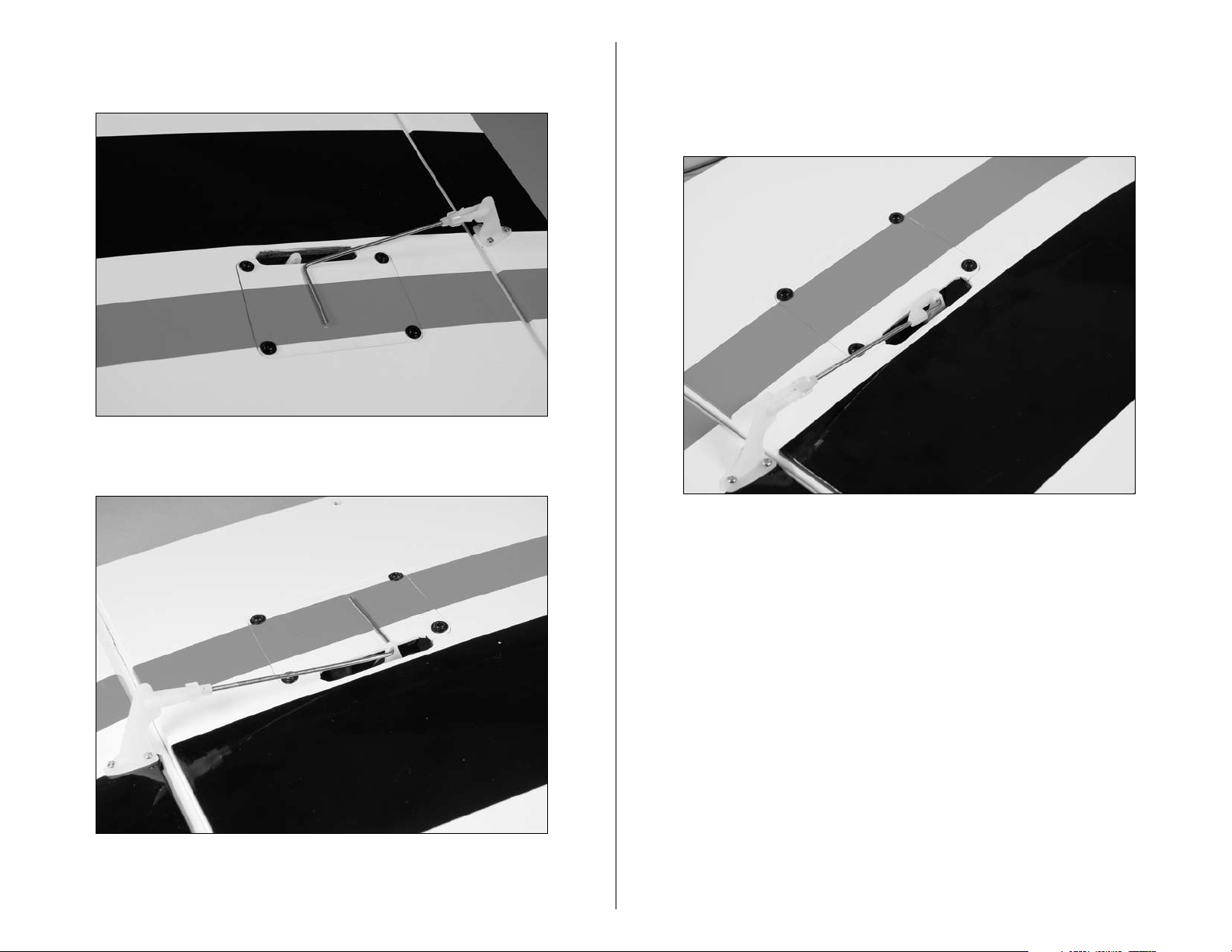
12. Make sure the flap servo is in the up position using
the radio system. Move the flaps to the up position and
use a 3mm x 5mm machine screw to secure the flap
linkage in the connector. Use threadlock on the screw to
prevent it from vibrating loose.
13. The following images show the three positions of
the flaps and the position of the servo in correlation
to these positions.
Flap Up:
24 E-flite Deuces Wild Assembly Manual
Page 25

Half Flap: Full Flap:
25E-flite Deuces Wild Assembly Manual
Page 26

Fixed Gear Installation
Required Parts
Wing center section Fuselage assembly
Main gear (right and left) Nose gear
Nylon clevis Brass pushrod connector
Silicone clevis retainer 3mm x 5mm machine screw
Nylon connector backplate
29 3/4-inch (755mm) pushrod wire
3mm x 8mm self-tapping countersink screw (12)
Required Tools and Adhesives
Pencil Phillips screwdriver: #1, #2
Drill Pin drill
Thin CA Side cutter
Threadlock Sandpaper
Drill bit: 5/64-inch (2mm), 3/32-inch (2.5mm)
Note: There is a left and right main gear unit. Please note
that the coil on the wire should be to the aft side and the
wheel towards the center of the wing.
1. Position the main landing gear in the opening in
the wing. Use a pencil to transfer the locations for the
mounting screws on to the landing gear rails. Please
ensure you center the main landing gear unit on the
mounting rails.
Note: Due to the model being designed for retracts and
fixed gear, you might need to slightly sand the flashing
off the edges of the fixed gear mounts to ensure an
interference free fit in the wing.
26 E-flite Deuces Wild Assembly Manual
Page 27

2. Use a drill and 3/32-inch (2.5mm) drill bit to drill the
locations for the four screws.
3. Apply 2–3 drops of thin CA into each of the holes.
This will harden the surrounding wood and provide a
harder surface for the screws, helping prevent them from
pulling loose on a hard landing.
4. Secure the main gear in the wing center section
using a #2 Phillips screwdriver and four 3mm x 8mm
self-tapping countersink screws.
5. Repeat Steps 1 through 4 to install the remaining main
landing gear.
27E-flite Deuces Wild Assembly Manual
Page 28

6. Position the nose landing gear in the opening in the
fuselage. Use a pencil to transfer the locations for the
mounting screws on the landing gear rails. Locate the
nose gear unit as far forward as possible while still being
able to rotate the nose gear strut wire.
8. Apply 2–3 drops of thin CA into each of the holes.
This will harden the surrounding wood and provide a
harder surface for the screws, helping prevent them from
pulling loose on a hard landing.
7. Use a drill and 3/32-inch (2.5mm) drill bit to drill the
locations for the four screws.
9. Thread a clevis onto the 29
wire. Make sure to slide a silicone clevis retainer onto the
3
/
-inch (755mm) pushrod
4
clevis before threading it onto the pushrod wire.
28 E-flite Deuces Wild Assembly Manual
Page 29

10. Connect the clevis to the center hole of the nose
wheel steering arm.
12. Secure the nose gear in the fuselage using a #2
Phillips screwdriver and four 3mm x 8mm self-tapping
countersink screws.
11. Slide the pushrod wire into the tube installed in the
front of the fuselage.
13. Use a #1 Phillips screwdriver to remove the nose
gear steering servo horn from the steering servo. Use
a pin drill and 5/64-inch (2mm) drill bit to enlarge the
outer hole of the steering servo horn.
29E-flite Deuces Wild Assembly Manual
Page 30

14. Slide the brass pushrod connector in the hole drilled
in the previous step.
15. Secure the connector to the servo horn using a
nylon connector backplate.
16. Use the radio system to center the steering servo.
Slide the brass connector onto the wire then secure it to
the steering servo. After centering the nose wheel, use a
3mm x 5mm machine screw to secure the pushrod wire
to the connector. Use threadlock on the machine screw
to ensure it will not vibrate loose during flight. You may
wish to trim the unused arms from the servo horn with a
pair of side cutters to ensure nothing interferes with servo
operation. Now check to ensure the nose wheel turns left
when you apply left rudder.
Note: If you need to adjust the steering so your model
tracks straight on the runway, use this screw to do so.
Use the rudder trim at the radio to correct for rudder trim
in the air only. You may wish to trim the pushrod wire
with side cutters once you have finalized the setting and
nose wheel steering adjustment.
30 E-flite Deuces Wild Assembly Manual
Page 31

Retract Gear Installation
Required Parts
Wing center section Fuselage assembly
Nose gear retract Main gear retract (right and left)
Brass pushrod connector (2) Quick disconnect (male and female)
Nylon connector backplate (2) Air line
Steering cable Cable crimp (4)
Cable fitting (2) 2mm x 8mm machine screw (2)
Air tank Air fill fitting
Air line T-fitting
3/16 inch wheel collars (4) (not included)
3mm x 8mm self-tapping countersink screw (12)
Required Tools and Adhesives
Hobby knife w/#11 blade Covering iron
Pencil Drill
Thin CA Pin drill
Phillips screwdriver: #1, #2 Side cutters
Pliers Silicone adhesive
Threadlock
Drill bit: 5/64-inch (2mm), 3/32-inch (2.5mm), 3/16-inch (5mm)
Note: The retracts for your Deuces Wild have been
designed to drop directly into the model with no
modifications. The wheel openings for the nose gear
should be very close to correct. If the nose gear hangs
up on the fuselage bottom once installed, you only need
to trim the balsa slightly to allow an interference-free
operation during retraction and extension. Use of other
retract systems may require modification to the airframe
which will have to be accomplished by the modeler.
You will note your retract wire struts are slightly different
from the ones shown in the manual. We did not have
production units available at the time of writing the
manual and needed to cut our wire to the correct length.
Your wires struts are pre-bent to the correct length and
have been sized for the Deuces Wild.
1. Use a hobby knife and #11 blade to trim the covering
to expose the opening for the nose gear retract. Trim the
covering leaving 1/8-inch (3mm) overlap of covering
from the inside edge of the opening so it can be ironed
down to add a clean finish to your model.
2. Use a covering iron to iron the covering inside the
edges of the retract opening.
31E-flite Deuces Wild Assembly Manual
Page 32

3. Position the nose landing gear in the opening in the
fuselage. Use a pencil to transfer the locations for the
mounting screws on the landing gear rails. Position the
unit as far forward as you can while still allowing the
nose gear to steer left and right.
5. Apply 2–3 drops of thin CA into each of the holes.
This will harden the surrounding wood and provide a
harder surface for the screws, helping prevent them from
pulling loose.
6. Cut a 10-inch (254mm) piece of air line. Attach the
4. Use a drill and 3/32-inch (2.5mm) drill bit to drill the
air line to the fitting on the nose gear retract.
locations for the four screws.
32 E-flite Deuces Wild Assembly Manual
Page 33

7. Locate the steering cable and two crimps. Use side
cutters to cut the cable into two equal lengths. Slide a
crimp onto the cable, then pass the cable through the
outside hole of the nose gear steering arm. Slide the
cable back through the crimp and compress the crimp
with pliers to secure the cable. Attach a cable to both
sides of the steering arm at the outer most hole.
8. Slide the steering cables into the pre-installed tubes
in the fuselage.
9. Secure the nose gear in the fuselage using a #2
Phillips screwdriver and four 3mm x 8mm self-tapping
countersink screws.
Note: You do not want any more than a 1/16-inch
(1.5mm) gap between the crimp and the aft portion of
the steering arm.
33E-flite Deuces Wild Assembly Manual
Page 34

10. Remove the wheel from the fixed nose gear using
a #2 Phillips screwdriver to loosen the screw that
secures the wheel collar. Slide the wheel collar without
the screw onto the nose gear wire, then the nose wheel.
Use the wheel collar from the fixed gear to secure the
wheel on the retract strut. A #2 Phillips screwdriver and
threadlock is used to tighten the screw that secures the
collar to the axle.
11. Remove the nose gear steering servo horn from the
steering servo. Use a pin drill and 5/64-inch (2mm) drill
bit to enlarge to outer holes of the steering servo horn.
12. Slide the two brass pushrod connectors in the holes
drilled in the previous step.
Note: The wheel is shown on the building surface for
clarity and contrast.
34 E-flite Deuces Wild Assembly Manual
Page 35

13. Secure the connectors to the servo horn using a
nylon connector backplates.
14. Center the steering servo using the radio and secure
the steering servo arm to the steering servo. Slide the
cable fittings into the pushrod connectors and temporarily
secure them using two 2mm x 8mm machine screws and
a #1 Phillips screwdriver. Ensure you set the cable fittings
so they are equal to each other when installed.
15. Slide a crimp onto the steering cable, then pass the
cable through the cable fittings. The cable will then go
through the crimp. Prepare both cables before crimping
the connectors. This will allow you to tensions the cables
lightly and center the nose gear before compressing the
crimps. Use side cutters to trim any excess cable.
Note: You do not want the steering cables to be real
tight. This will cause your nose gear to not lock down
during extension. These should be a small amount of play
in the steering cables (approximately 1 degree left and
right on the nose wheel) to ensure correct operation.
35E-flite Deuces Wild Assembly Manual
Page 36

16. Cut a 3-inch (76mm) piece of air line and attach it to
the air fill fitting.
18. Use the hardware supplied to secure the fitting in the
fuselage.
17. Use a hobby knife to remove the covering from
the fuselage to expose the pre-drilled hole for the air
19. Cut a 3-inch (76mm) piece of air line and attach it to
the air tank.
fill fitting.
36 E-flite Deuces Wild Assembly Manual
Page 37

20. Use silicone adhesive to secure the air tank in the
fuselage. The air line between the air fill fitting and air
tank are connected using a T-fitting. Cut and attach a
3-inch (76mm) piece of air line to the fitting. Attach a
female quick disconnect to the 3-inch line coming from
the T-fitting and the retract air line. Attach a male quick
disconnect to the 3-inch (76mm) line coming from the
T-fitting and air tank air line.
21. Use a hobby knife and #11 blade to trim the
covering to expose the opening for the main gear retract.
Trim the covering for the wheel well making a 1/8-inch
(3mm) overlap of covering from the inside edge of the
opening so it can be ironed down to add a clean finish
to your model.
Note: The air tank shown in the photos is not of the
correct size. The correct size air tank is included with
your retract package.
37E-flite Deuces Wild Assembly Manual
Page 38

22. Use a covering iron to iron the covering inside the
edges of the retract opening.
23. Position the main landing gear in the opening in
the wing. Use a pencil to transfer the locations for the
mounting screws on to the landing gear rails.
24. Use a drill and 3/32-inch (2.5mm) drill bit to drill the
locations for the four screws.
25. Apply 2–3 drops of thin CA into each of the holes.
This will harden the surrounding wood and provide a
harder surface for the screws, helping prevent them from
pulling loose.
38 E-flite Deuces Wild Assembly Manual
Page 39

26. Cut a 10-inch (254mm) piece of air line. Attach the
air line to the fitting on the main gear retract.
27. Secure the main gear in the wing center section using
a #2 Phillips screwdriver and four 3mm x 8mm selftapping countersink screws.
28. Remove the wheel from the fixed main gear using a
#2 Phillips screwdriver to loosen the screw that secures
the wheel collar. Use a drill and 3/16-inch (5mm) drill bit
to enlarge the hole in the main wheel.
39E-flite Deuces Wild Assembly Manual
Page 40

29. Slide a 3/16-inch wheel collar without a screw onto
the main gear wire, then the wheel. Use a 3/16-inch
wheel collar to secure the wheel on the retract strut. A
#2 Phillips screwdriver is used to tighten the screw that
secures the collar to the axle.
Retract Servo Installation
Required Parts
Wing center section Actuator valve
Plywood valve mount Nylon clevis
Clevis retainer 3-inch (76mm) pushrod
Air line Air line T-fitting (2)
Brass pushrod connector Connector backplate
Tie wrap (4) Servo w/hardware
3mm x 5mm machine screw Plywood servo tray
Quick disconnect (male and female)
Required Tools and Adhesives
Scissors Pencil
Pin drill Side cutters
Mixing cups Mixing sticks
6-minute epoxy Medium CA
Thin CA Phillips screwdriver: #1
Low-tack masking tape Threadlock
Drill bit: 1/16-inch (1.5mm), 5/64-inch (2mm)
1. Use 6-minute epoxy to secure the retract servo tray in
the wing as shown.
Note: The wheel is shown on the building surface for
clarity and contrast.
30. Repeat Steps 21 through 29 to install the remaining
main gear retract.
40 E-flite Deuces Wild Assembly Manual
Page 41

Hint: Cut the string routed through the wing into two
pieces and tape them to the wing as shown to keep them
out of the way during the retract servo install.
2. Position the retract servo in the wing. Use a pencil to
transfer the locations for the servo mounting screws to the
servo tray.
3. Use a pin drill and 1/16-inch (1.5mm) drill bit to drill
the four holes for the servo mounting screws.
4. Apply 2–3 drops of thin CA into each of the holes to
harden the surrounding wood. This will provide a harder
surface for the screws to bite into when installed.
41E-flite Deuces Wild Assembly Manual
Page 42

5. Secure the retract servo in the wing using the
hardware provided with the servo and a #1 Phillips
screwdriver. The servo is installed with the output shaft
and horn towards the trailing edge of the wing.
6. Attach the actuator valve to the plywood valve mount
using the hardware provided with the valve.
7. Use medium CA to attach the valve mount as shown.
8. Use a T-fitting to connect the air lines from the main
gear. Attach a 3-inch (76mm) piece of air line to the
T-fitting. Use either side cutters or scissors to cut the air
line.
42 E-flite Deuces Wild Assembly Manual
Page 43

9. Attach a T-fitting to the air line from the previous step.
On one side of the T-fitting, attach a 3-inch (76mm)
section of air line to the actuator valve. On the other side,
connect a 6-inch (152mm) section of air line, then a male
quick disconnect that mates to the female disconnect on
the nose gear retract line.
11. Remove the servo horn from the retract servo. Use a
pin drill and 5/64-inch (2mm) drill bit to enlarge to outer
hole of the retract servo horn.
10. Connect a 6-inch piece of air line to the remaining
fitting on the actuator valve. A female quick disconnect
that mates to the male quick disconnect on the line
coming from the air tank will need to be attached to
this line.
12. Slide the brass pushrod connector in the hole drilled
in the previous step.
43E-flite Deuces Wild Assembly Manual
Page 44

13. Secure the connector to the servo horn using a nylon
connector backplate. You may use side cutters to trim the
unused arms on the servo control horn.
14. Inside the radio programming menu of travel
adjustment, turn the travel adjustment down to 0 on both
sides of the gear channel. Set the control horn on the
servo where it sits at the neutral position as shown in the
photo. Install the servo horn on the retract servo.
Note: You will need your transmitter and receiver for the
next steps to set up your retract end points.
44 E-flite Deuces Wild Assembly Manual
Page 45

15. Thread a clevis onto a the 3-inch (76mm) pushrod
wire. Make sure to slide a silicone clevis retainer onto
the clevis before threading it onto the pushrod wire. Slide
the pushrod into the pushrod connector and align the
clevis with the hole in the actuator valve. Now hook up
the clevis and set the valve to where the plunger is half
way in between either side. Using threadlock, tighten the
machine screw and proceed to the next step.
16. Now with the radio on, flip the retract switch to either
side and in the travel adjust menu continue to dial in
throw on one side until the plunger just touches one side.
Now flip the retract switch in the opposite direction and
turn the travel adjustment up until the plunger just touches
the opposing side. Your retract servo should now be set
up and not binding. Trim the pushrod with side cutters
once you have the final adjustments complete.
45E-flite Deuces Wild Assembly Manual
Page 46

Hint: Try to keep the amounts equal for both up and
down. You may need to remove the servo horn and
adjust it on the servo shaft at least once during the
alignment process.
Aileron and Throttle Servo Extensions
Required Parts
Wing center section Y-harness (2)
9-inch (228mm) servo extension (2)
6-inch (152mm) servo extension (2)
Required Tools and Adhesives
Low-tack tape Dental floss
1. Prepare the aileron servo extension by connecting two
9-inch (228mm) extensions to a Y-harness. The throttle
extension will require two 6-inch (152mm) extensions
and a Y-harness. Make sure to use string, dental floss,
or a commercially available connectors to secure the
extensions to the Y-harness.
Note: We used low-tack tape on each aileron extension
lead to differentiate it from the throttle extension.
46 E-flite Deuces Wild Assembly Manual
Page 47

2. Tie the string on one side to the end of the throttle and
aileron extensions. Repeat for the opposite side.
3. Use the string to pull the aileron and throttle
extensions through the wing. The throttle extension
will require routing through the opening above the
wing tube as shown.
47E-flite Deuces Wild Assembly Manual
Page 48

Power 25 Motor Installation
Required Parts
Motor w/X-mount (2) Motor nacelle (right and left)
4-40 x 1-inch socket head screw (8)
Required Tools and Adhesives
Phillips screwdriver: #2 Threadlock
Ball driver: 3/32-inch
1. Attach the X-mount to the Power 25 motor using the
hardware provided with the motor and a #2 Phillips
screwdriver. Make sure to use threadlock on the screws to
prevent them from vibrating loose.
2. Pass the wires from the motor through the gap
between the engine nacelle and firewall. The motor is
secured to the firewall using four 4-40 x 1-inch socket
head screws and a 3/32-inch ball wrench.
3. Repeat Steps 1 and 2 to install the remaining motor.
48 E-flite Deuces Wild Assembly Manual
Page 49

Power 32 Motor Installation
Required Parts
Motor w/X-mount (2) Spacer (8)
Motor nacelle (right and left)
4-40 x 1-inch socket head screw (8)
Required Tools and Adhesives
Phillips screwdriver: #2 Threadlock
Ball driver: 3/32-inch
Note: Using the Power 32 will provide you with
strong aerobatic performance. Due to the nacelle
design, installing the Power 32 takes more time as
you will need to assemble the motor to its X-mount
inside the nacelle. We have found it easiest to
accomplish this while the nacelle is pointing towards
the ground and holding the motor inside the nacelle
while we attach the X-mount. The X-mount should sit on
the back of the motor during this, providing you the
ability to install each screw one at a time.
1. The Power 32 motor will require spacers be installed
between the mount and firewall. The image below
illustrates this installation as it is difficult to see this spacer
inside the engine nacelle when the motor is installed.
49E-flite Deuces Wild Assembly Manual
Page 50

2. Place the X-mount for the motor into the nacelle.
Ensure the counter sunk holes in the X-mount face
towards the firewall.
4. Pass the wires from the motor through the gap
between the engine nacelle and firewall. The motor will
be secured to the firewall using four 4-40 x 1-inch socket
head screws and a 3/32-inch ball wrench in a later step.
3. Position the motor inside the nacelle.
50 E-flite Deuces Wild Assembly Manual
Page 51

5. The screws to attach the X-mount to the motor will
need to be installed using the openings from the backside
of the firewall. Work slowly to install the four screws, and
don't forget to use threadlock on these screws or they will
vibrate loose.
6. After the X-mount has been attached to the motor,
secure the X-mount to the firewall. Use the spacers
between the mount and firewall as shown previously.
Use a 3/32-inch ball driver to tighten the four 4-40 x
1-inch socket head screws that secure the X-mount to
the firewall. Make sure to use threadlock to prevent the
screws from vibrating loose.
Hint: You may want to magnetize your Phillips
screwdriver to hold the screw during this operation.
51E-flite Deuces Wild Assembly Manual
Page 52

7. Repeat Steps 1 through 6 to install the remaining
Wing Right Wing Left
motor in the nacelle.
Propeller and Spinner Installation
Required Parts
Propeller (left and right) Spinner w/screw (left and right)
Propeller adapter (2) Wing center section
60-amp speed control (2) Hook and loop tape
Motor nacelle (right and left)
Required Tools and Adhesives
Phillips screwdriver: #1 6-minute epoxy
Paper towels Rubbing alcohol
Canopy glue Mixing cups
Mixing sticks Low-tack tape
Rotary tool w/ high speed cutting bit
Note: Your model is equipped with counter-rotating
spinners. When viewed from the cockpit, the left wing
motor will rotate clockwise and the right wing motor will
rotate counterclockwise. The standard rotation propeller
is installed on the left motor and the pusher propeller is
installed on the right motor.
52 E-flite Deuces Wild Assembly Manual
Page 53

1. Pass the adapter for your motor into the spinner
backplate. Slide the propeller onto the adapter.
Note: It may be necessary to relieve the back opening
in the spinner back plate to accept the E-flite prop collet.
We use a rotary tool with a high speed bit to accomplish
this.
2. Thread the adapter nut onto the adapter, but do not
tighten the nut at this time.
3. Slide the adapter assembly onto the motor shaft.
With a gap of 5/64-inch (2mm) between the spinner
backplate and front of the nacelle, tighten the adapter
nut to secure the adapter to the motor shaft.
4. Use a #1 Phillips screwdriver to tighten the two 3mm x
10mm self-tapping screws that secure the spinner cone to
the spinner backplate.
53E-flite Deuces Wild Assembly Manual
Page 54

5. Use hook and loop tape to attach the speed control to
the inside of the motor nacelle.
6. Test fit the motor nacelles to the wing. The E-flite decal
will face out toward the tip of the wing.
7. Once satisfied with the fit, remove the nacelle from the
wing. Use 6-minute epoxy to glue the nacelle to the wing.
Apply the epoxy to the exposed bare plywood of the
wing, which is the junction where the nacelle meets the
wing. Also apply epoxy to the inside of the nacelle where
it will meet the plywood. Make a nice fillet of epoxy at
this joint. Use low-tack tape to hold the nacelle in position
while the epoxy cures.
54 E-flite Deuces Wild Assembly Manual
Page 55

Note: Use paper towels and rubbing alcohol to clean up
any excess epoxy that squeezes out from the nacelles
onto the wing in this step.
8. Once the epoxy has fully cured, use canopy glue to
glue the aft edges of the nacelle to the wing top and
bottom wing covering. The covering does not need to be
removed from the wing for this. Use low-tack tape to hold
the nacelle tight against the wing while the canopy glue
cures.
9. If using the E-flite 60 Amp ESC, you only need one
of the BEC's to be active. To disarm the BEC on one of
the ESC's, you will need to remove the red wire from the
servo plug on the ESC. Tape this wire back on itself once
completed. Now connect the lead from the ESC to the
previously installed extension lead. Ensure you use some
dental floss or a commercially available device to secure
the connection.
10. Repeat Steps 1 through 9 to install the remaining
propeller, spinner and ESC.
55E-flite Deuces Wild Assembly Manual
Page 56

Wing Installation
Required Parts
Wing panel (right and left) Wing center section
Wing tube (2) 1/4-20 x 2-inch nylon bolt (2)
4-40 x 1-inch socket head bolt (2)
Required Tools and Adhesives
Ball driver: 3/32-inch Flat screwdriver
1. Slide the wing tube into the socket in the wing
center section.
2. Slide an outer wing panel onto the wing tube. Guide
the tab with the blind nut into the appropriate slot of the
wing center section. Don't forget to plug the extension
from the center section to the aileron servo.
56 E-flite Deuces Wild Assembly Manual
Page 57

3. With the outer wing panel tight against the wing
center section, use a 3/32-inch ball driver to install the
4-40 x 1-inch socket head bolt that secures the outer
panel to the center section. Complete for the opposite
wing panel.
4. Position the wing on the fuselage. Use two 1/4-20 x
2-inch nylon bolts and a flat screwdriver to secure the
wing to the fuselage. Ensure you connect the air lines as
well as the servo wires from the wing into the respective
ports on the receiver before fully installing the wing.
Canopy and Gear Door Installation
Required Parts
Fuselage assembly Canopy
Tie wrap (4) Main gear door (right and left)
Required Tools and Adhesives
Low-tack tape Canopy glue
Side cutters Drill
Drill bit: 5/64-inch (2mm)
Silicone adhesive
Note: You may wish to install the optional cockpit kit at
this time. Instructions have been provided with that kit on
how to install it into your Deuces Wild.
1. Use canopy glue to attach the canopy to the fuselage.
Use low-tack tape to hold the canopy in position until the
glue has fully cured.
57E-flite Deuces Wild Assembly Manual
Page 58

2. Fill the retract system with a commercially available air
pump and operate the retracts. With the main gear in the
UP position, apply a bead of silicone adhesive to the strut
wire and tape the gear cover in position on the wing. Set
the wing aside and allow the adhesive to fully cure.
4. Use a tie wrap near the top and bottom of the gear
cover to complete their installation. Use side cutters to
trim the excess to prevent the tie wraps from interfering
with the wheel or operation of the retracts.
3. Once cured, drill a 5/64-inch (2mm) hole on each
side of the wire struts for the tie wraps to go through.
Drill the holes as close to the top and bottom of the cover
as possible.
Note: It is easier to remove the wheel then install the
tie wrap near the wheel. Always remember to use
threadlock on metal-to-metal fasteners to prevent them
from vibrating loose.
5. Repeat Steps 2 through 4 to install the remaining
gear cover.
58 E-flite Deuces Wild Assembly Manual
Page 59

Center of Gravity and
Nose Cone Installation
Required Parts
Airframe
Nose Cone
Required Tools and Adhesives
Canopy Glue
Low-tack tape
Stick on weights (if needed)
An important part of preparing the aircraft for flight is properly
balancing the model.
Caution: Do not inadvertently skip this step!
1. The recommended Center of Gravity (CG) location for
3
the Deuces Wild is 3
from the leading edge of the wing. Mark the location for
the Center of Gravity on the top of the wing next to the
fuselage as shown.
1
/
–4
/
4
-inch (95–103mm) back
16
When balancing your Deuces Wild, support the plane
upsidedown at the marks made on the top of the wing with your
fingers or a commercially available balancing stand. Adjust
components as necessary so the model hangs level or slightly
nose down. This is the correct balance point for your model.
You might find with the different power and landing gear
configurations that you need to add a small amount of weight
to either the front or back of the fuselage to achieve the correct
balance.
If using retracts, balance the model with the gear retracted.
After the first flights, the CG position can be adjusted for your
personal preference.
2. Use canopy clue to attach the nose cone to the front
of the fuselage. Use low-tack tape to hold the cone in
position until the glue has fully cured.
Important: The Center of Gravity must be checked
before fully installing the nose cone. Due to the multiple
configurations of retracts, fixed gear, and motor
options, it is common to require some nose weight or
possibly some tail weight to get the model to properly
balance. The amount necessary may be small, and some
configurations do not need weight at all. If you need
nose weight, it is best to install it at the very far forward
point of the nose cone.
59E-flite Deuces Wild Assembly Manual
Page 60

Control Throws
1. Turn on the transmitter and receiver of your Deuces
Wild. Check the movement of the rudder using the
transmitter. When the stick is moved right, the rudder
should also move right. Reverse the direction of the servo
at the transmitter if necessary.
2. Check the movement of the elevator with the radio
system. Moving the elevator stick down will make the
airplane elevator move up.
3. Check the movement of the ailerons with the radio
system. Moving the aileron stick right will make the right
aileron move up and the left aileron move down.
Ailerons High Rate Low Rate
Up 5/8-inch Up 3/8-inch
Down 5/8-inch Down 3/8-inch
25% Expo 10% Expo
Elevator High Rate Low Rate
Up 7/8-inch Up 1/2-inch
Down 7/8-inch Down 1/2-inch
20% Expo 10% Expo
Rudder High Rate Low Rate
1
/
Left 1
Right 1
-inch Left 1/2-inch
4
1
/
-inch Right 1/2-inch
4
4. Use a ruler to adjust the throw of the elevator, ailerons
and rudder. Adjust the position of the pushrod at the
control horn to achieve the following measurements when
moving the sticks to their endpoints.
15% Expo 0% Expo
Flaps Takeoff Landing
1
/
1
-inch 5/8-inch
8
Elevator Compensation With Flaps
3/32-inch down 5/32-inch down
Note: Measurements are taken at the widest point on
the surface.
These are general guidelines measured from our own flight tests.
You can experiment with higher rates to match your preferred
style of flying.
60 E-flite Deuces Wild Assembly Manual
Page 61

Range Test Your Radio
Preflight
1. Before each flying session, be sure to range check
your radio. This is accomplished by turning on your
transmitter with the antenna collapsed. Turn on the
receiver in your airplane. With your airplane on the
ground and the engine running, you should be able to
walk 30 paces (approximately 100 feet) away from your
airplane and still have complete control of all functions.
If not, don’t attempt to fly! Have your radio equipment
checked out by the manufacturer.
2. Double-check that all controls (aileron, elevator, rudder
and throttle) move in the correct direction.
3. Be sure that your transmitter batteries are fully
charged, per the instructions included with your radio.
Check Your Radio
Before going to the field, be sure that your batteries are fully
charged per the instructions included with your radio. Charge
both the transmitter and receiver pack for your airplane. Use
the recommended charger supplied with your particular radio
system, following the instructions provided with the radio. In
most cases, the radio should be charged the night before going
out flying.
Before each flying session, be sure to range check your radio.
See your radio manual for the recommended range and
instructions for your radio system. Each radio manufacturer
specifies different procedures for their radio systems. Next, start
the motor. With the model securely anchored, check the range
again. The range test should not be significantly affected. If it is,
don’t attempt to fly! Have your radio equipment checked out by
the manufacturer.
Note: Keep loose items that can get entangled in
the propeller away from the prop. These include
loose clothing, or other objects such as pencils and
screwdrivers. Especially keep your hands away from the
propeller.
Double-check that all controls (aileron, elevator, rudder and
throttle) move in the correct direction.
Check the radio installation and make sure all the control
surfaces are moving correctly (i.e. the correct direction and with
the recommended throws). Test run the motor and make sure
it transitions smoothly from off to full throttle and back. Also
ensure the engine is installed according to the manufacturer’s
instructions, and it will operate consistently.
Check all the control horns, servo horns, and clevises to make
sure they are secure and in good condition. Replace any items
that would be considered questionable. Failure of any of these
components in flight would mean the loss of your aircraft.
61E-flite Deuces Wild Assembly Manual
Page 62

Flying Your Deuces Wild
With the counter-rotating props the elimination of torque
delivers straight ahead acceleration and smooth flight
characteristics. Plug in your batteries and install the battery
hatches. Now move the throttle trim up until the motors come
to life. This is your flight idle.
Taxi out to the runway and align yourself with the center line.
Leave the flaps up for your first takeoff. They are not really
needed for takeoff at all. Power up and steer the model straight.
As the model approaches takeoff speed, pull back slightly on the
elevator. Once you are airborne, retract the landing gear if you
have installed retracts. Now you can enjoy the flight envelope of
slow to high speed flight and you will find the Deuces Wild fully
capable of just about any aerobatic maneuver you can think of.
Setting up for landing, you will find the Deuces Wild to slow
up very well in the flight pattern. On the upwind leg drop the
landing gear and the flaps. If the model balloons up badly,
you will need more down elevator compensation to correct this.
If the model dives down, you have too much down elevator
compensation and will need to correct this. If you feel like
the model is uncontrollable with too much elevator with the
flaps down, you should retract the flaps and land, make an
adjustment and try again. The model lands very well without
the flaps. Make these adjustments on the elevator in 1/16-inch
increments. The settings in the book are close when the CG
is set as per the manual at around 4 inches. These elevator
compensations will change slightly based on the CG setting of
your model.
Single engine performance
The model has been designed from the beginning to be a
very gentle flying model that can deliver performance when
requested. If you lose a motor, the model will still fly very well,
but your climb performance will suffer slightly. The best thing
is to not turn into the dead engine, but with the larger tail, we
have made turns using ailerons only into the dead motor along
with touch and go's. We do not recommend you continue flying
if you lose a motor. Set up and land and determine what the
problem is.
We hope you enjoy flying your Deuces Wild ARF as much as
we do.
Happy Landings!
You will find this model floats very well and lands very slowly.
It has no real bad habits and is one of the easiest flying models
you will ever fly.
62 E-flite Deuces Wild Assembly Manual
Page 63

Safety, Precautions, and Warnings
Warranty Information
As the user of this product, you are solely responsible for
operating it in a manner that does not endanger yourself
and others or result in damage to the product or the property
of others.
Carefully follow the directions and warnings for this and any
optional support equipment (chargers, rechargeable battery
packs, etc.) that you use.
This model is controlled by a radio signal that is subject to
interference from many sources outside your control. This
interference can cause momentary loss of control so it is
necessary to always keep a safe distance in all directions around
your model, as this margin will help to avoid collisions or injury.
• Always operate your model in an open area away from cars,
traffic or people.
• Avoid operating your model in the street where injury or
damage can occur.
• Never operate the model out into the street or populated areas
for any reason.
• Never operate your model with low transmitter batteries.
• Carefully follow the directions and warnings for this and any
optional support equipment (chargers, rechargeable battery
packs, etc.) that you use.
• Keep all chemicals, small parts and anything electrical out of
the reach of children.
• Moisture causes damage to electronics. Avoid water exposure
to all equipment not specifically designed and protected for
this purpose.
Warranty Period
Horizon Hobby, Inc., (Horizon) warranties that the Products purchased
(the “Product”) will be free from defects in materials and workmanship
at the date of purchase by the Purchaser.
Limited Warranty
(a) This warranty is limited to the original Purchaser ("Purchaser") and
is not transferable. REPAIR OR REPLACEMENT AS PROVIDED UNDER
THIS WARRANTY IS THE EXCLUSIVE REMEDY OF THE PURCHASER.
This warranty covers only those Products purchased from an
authorized Horizon dealer. Third party transactions are not covered
by this warranty. Proof of purchase is required for warranty claims.
Further, Horizon reserves the right to change or modify this warranty
without notice and disclaims all other warranties, express or implied.
(b) Limitations- HORIZON MAKES NO WARRANTY OR
REPRESENTATION, EXPRESS OR IMPLIED, ABOUT NONINFRINGEMENT, MERCHANTABILITY OR FITNESS FOR A
PARTICULAR PURPOSE OF THE PRODUCT. THE PURCHASER
ACKNOWLEDGES THAT THEY ALONE HAVE DETERMINED THAT
THE PRODUCT WILL SUITABLY MEET THE REQUIREMENTS OF THE
PURCHASER’S INTENDED USE.
(c) Purchaser Remedy- Horizon's sole obligation hereunder
shall be that Horizon will, at its option, (i) repair or (ii) replace, any
Product determined by Horizon to be defective. In the event of a
defect, these are the Purchaser's exclusive remedies. Horizon reserves
the right to inspect any and all equipment involved in a warranty
claim. Repair or replacement decisions are at the sole discretion of
Horizon. This warranty does not cover cosmetic damage or damage
due to acts of God, accident, misuse, abuse, negligence, commercial
use, or modification of or to any part of the Product. This warranty
does not cover damage due to improper installation, operation,
maintenance, or attempted repair by anyone other than Horizon.
Return of any goods by Purchaser must be approved in writing by
Horizon before shipment.
63E-flite Deuces Wild Assembly Manual
Page 64

Damage Limits
Questions, Assistance, and Repairs
HORIZON SHALL NOT BE LIABLE FOR SPECIAL, INDIRECT OR
CONSEQUENTIAL DAMAGES, LOSS OF PROFITS OR PRODUCTION
OR COMMERCIAL LOSS IN ANY WAY CONNECTED WITH THE
PRODUCT, WHETHER SUCH CLAIM IS BASED IN CONTRACT,
WARRANTY, NEGLIGENCE, OR STRICT LIABILITY. Further, in no
event shall the liability of Horizon exceed the individual price of the
Product on which liability is asserted. As Horizon has no control over
use, setup, final assembly, modification or misuse, no liability shall be
assumed nor accepted for any resulting damage or injury. By the act
of use, setup or assembly, the user accepts all resulting liability.
If you as the Purchaser or user are not prepared to accept the liability
associated with the use of this Product, you are advised to return this
Product immediately in new and unused condition to the place of
purchase.
Law: These Terms are governed by Illinois law (without regard to
conflict of law principals).
Safety Precautions
This is a sophisticated hobby Product and not a toy. It must be
operated with caution and common sense and requires some basic
mechanical ability. Failure to operate this Product in a safe and
responsible manner could result in injury or damage to the Product or
other property. This Product is not intended for use by children without
direct adult supervision. The Product manual contains instructions for
safety, operation and maintenance. It is essential to read and follow
all the instructions and warnings in the manual, prior to assembly,
setup or use, in order to operate correctly and avoid damage or
injury.
Your local hobby store and/or place of purchase cannot provide
warranty support or repair. Once assembly, setup or use of the
Product has been started, you must contact Horizon directly. This will
enable Horizon to better answer your questions and service you in the
event that you may need any assistance. For questions or assistance,
please direct your email to productsupport@horizonhobby.com, or call
877.504.0233 toll free to speak to a service technician.
Inspection or Repairs
If this Product needs to be inspected or repaired, please call for a
Return Merchandise Authorization (RMA). Pack the Product securely
using a shipping carton. Please note that original boxes may be
included, but are not designed to withstand the rigors of shipping
without additional protection. Ship via a carrier that provides tracking
and insurance for lost or damaged parcels, as Horizon is not
responsible for merchandise until it arrives and is accepted
at our facility. A Service Repair Request is available at www.
horizonhobby.com on the “Support” tab. If you do not have internet
access, please include a letter with your complete name, street
address, email address and phone number where you can be reached
during business days, your RMA number, a list of the included items,
method of payment for any non-warranty expenses and a brief
summary of the problem. Your original sales receipt must also be
included for warranty consideration. Be sure your name, address, and
RMA number are clearly written on the outside of the shipping carton.
Warranty Inspection and Repairs
To receive warranty service, you must include your original
sales receipt verifying the proof-of-purchase date. Provided warranty
conditions have been met, your Product will be repaired or replaced
free of charge. Repair or replacement decisions are at the sole
discretion of Horizon Hobby.
64 E-flite Deuces Wild Assembly Manual
Page 65

Non-Warranty Repairs
Should your repair not be covered by warranty the repair
will be completed and payment will be required without
notification or estimate of the expense unless the expense
exceeds 50% of the retail purchase cost.
item for repair you are agreeing to payment of the repair without
notification. Repair estimates are available upon request. You must
include this request with your repair. Non-warranty repair estimates
will be billed a minimum of ½ hour of labor. In addition you will be
billed for return freight. Please advise us of your preferred method of
payment. Horizon accepts money orders and cashiers checks, as well
as Visa, MasterCard, American Express, and Discover cards.
By submitting the
All other Products requiring warranty inspection or repair should be
shipped to the following address:
Horizon Support Team
4105 Fieldstone Road
Champaign, Illinois 61822
USA: Please call 1 877 504 0233 or visit horizonhobby.com
to find our distributor for your country for support with any
questions or concerns regarding this product or warranty.
UK: Please call +44 1279 641 097 or sales@horizonhobby.
co.uk with any questions or concerns regarding this product or
warranty.
If you choose to pay by credit card, please include your credit card
number and expiration date. Any repair left unpaid or unclaimed
after 90 days will be considered abandoned and will be disposed of
accordingly.
Please note: non-warranty repair is only available
on electronics and model engines.
Electronics and engines requiring inspection or repair should be
shipped to the following address:
Horizon Service Center
4105 Fieldstone Road
Champaign, Illinois 61822
or
Horizon Hobby UK
Units 1-4, Ployters Road
Staple Tye - Southern Way
Harlow
Essex
CM187NS
United Kingdom
or
Horizon Technischer Service
Otto-Hahn-Str. 9a
25337 Elmshorn
Germany
Germany: Please call +49 4121 46199 66 or service@
horizonhobby.de with any questions or concerns regarding
this product or warranty.
Instructions for Disposal of WEEE by
Users in the European Union
This product must not be disposed of with other waste. Instead,
it is the user’s responsibility to dispose of their waste equipment
by handing it over to a designated collection point for the
recycling of waste electrical and electronic equipment. The
separate collection and recycling of your waste equipment at
the time of disposal will help to conserve natural resources and
ensure that it is recycled in a manner that protects human health
and the environment. For more information about where you
can drop off your waste equipment for recycling, please contact
your local city office, your household waste disposal service or
where you purchased the product.
65E-flite Deuces Wild Assembly Manual
Page 66

2008 Official AMA National
Model Aircraft Safety Code
GENERAL
1) I will not fly my model aircraft in sanctioned events, air shows
or model flying demonstrations until it has been proven to be
airworthy by having been previously, successfully flight tested.
2) I will not fly my model higher than approximately 400 feet within 3
miles of an airport without notifying the airport operator. I will give
right-of-way and avoid flying in the proximity of full-scale aircraft.
Where necessary, an observer shall be utilized to supervise flying
to avoid having models fly in the proximity of full-scale aircraft.
3) Where established, I will abide by the safety rules for the flying
site I use, and I will not willfully or deliberately fly my models in a
careless, reckless and/or dangerous manner.
4) The maximum takeoff weight of a model is 55 pounds, except
models flown under Experimental Aircraft rules.
5) I will not fly my model unless it is identified with my name and
address or AMA number on or in the model. (This does not apply
to models while being flown indoors.)
6) I will not operate models with metal-bladed propellers or with
gaseous boosts, in which gases other than air enter their internal
combustion engine(s); nor will I operate models with extremely
hazardous fuels such as those containing tetranitromethane or
hydrazine.
RADIO CONTROL
1) I will have completed a successful radio equipment ground range
check before the first flight of a new or repaired model.
2) I will not fly my model aircraft in the presence of spectators until I
become a qualified flier, unless assisted by an experienced helper.
3) At all flying sites a straight or curved line(s) must be established
in front of which all flying takes place with the other side for
spectators. Only personnel involved with flying the aircraft are
allowed at or in front of the flight line. Intentional flying behind the
flight line is prohibited.
4) I will operate my model using only radio control frequencies
currently allowed by the Federal Communications Commission.
(Only properly licensed Amateurs are authorized to operate
equipment on Amateur Band frequencies.)
5) Flying sites separated by three miles or more are considered safe
from site-to-site interference, even when both sites use the same
frequencies. Any circumstances under three miles separation
require a frequency management arrangement, which may be
either an allocation of specific frequencies for each site or testing
to determine that freedom from interference exists. Allocation plans
or interference test reports shall be signed by the parties involved
and provided to AMA Headquarters.
Documents of agreement and reports may exist between (1) two
or more AMA Chartered Clubs, (2) AMA clubs and individual
AMA members not associated with AMA Clubs, or (3) two or
more individual AMA members.
6) For Combat, distance between combat engagement line
and spectator line will be 500 feet per cubic inch of engine
displacement. (Example: .40 engine = 200 feet.); electric motors
will be based on equivalent combustion engine size. Additional
safety requirements will be per the RC Combat section of the
current Competition Regulations.
7) At air shows or model flying demonstrations, a single straight line
must be established, one side of which is for flying, with the other
side for spectators.
8) With the exception of events flown under AMA Competition rules,
after launch, except for pilots or helpers being used, no powered
model may be flown closer than 25 feet to any person.
9) Under no circumstances may a pilot or other person touch a
powered model in flight.
66 E-flite Deuces Wild Assembly Manual
Page 67

67E-flite Deuces Wild Assembly Manual
Page 68

13397
© 2008 Horizon Hobby, Inc.
4105 Fieldstone Road
Champaign, Illinois 61822
(877) 504-0233
horizonhobby.com
E-fliteRC.com
 Loading...