

Page 1
CARBON-Z YAK 54
Instruction Manual
Bedienungsanleitung
Manuel d’utilisation
Manuale di Istruzioni
Page 2

EN2EN
Page 3
NOTICE
All instructions, warranties and other collateral documents are subject to change at the sole discretion of
Horizon Hobby, Inc. For up-to-date product literature, visit http://www.horizonhobby.com and click on the
support tab for this product.
Meaning of Special Language:
The following terms are used throughout the product literature to indicate various levels of potential harm
when operating this product:
NOTICE: Procedures, which if not properly followed, create a possibility of physical property damage AND little
or no possibility of injury.
CAUTION: Procedures, which if not properly followed, create the probability of physical property damage AND a
possibility of serious injury.
WARNING: Procedures, which if not properly followed, create the probability of property damage, collateral
damage, and serious injury OR create a high probability of superficial injury.
WARNING: Read the ENTIRE instruction manual to become familiar with the features of the product before
operating. Failure to operate the product correctly can result in damage to the product, personal property
and cause serious injury.
This is a sophisticated hobby product and NOT a toy. It must be operated with caution and common sense and
requires some basic mechanical ability. Failure to operate this Product in a safe and responsible manner could
result in injury or damage to the product or other property. This product is not intended for use by children
without direct adult supervision. Do not attempt disassembly, use with incompatible components or augment
product in any way without the approval of Horizon Hobby, Inc. This manual contains instructions for safety,
operation and maintenance. It is essential to read and follow all the instructions and warnings in the manual,
prior to assembly, setup or use, in order to operate correctly and avoid damage or serious injury.
Safety Precautions and Warnings
As the user of this product, you are solely
responsible for operating in a manner that does not
endanger yourself and others or result in damage to
the product or the property of others.
This model is controlled by a radio signal subject
to interference from many sources outside your
control. This interference can cause momentary loss
of control so it is advisable to always keep a safe
distance in all directions around your model, as this
margin will help avoid collisions or injury.
Age Recommendation: Not for children under 14
years. This is not a toy.
• Never operate your model with low transmitter
batteries.
• Always operate your model in an open area away
from cars, traffic or people.
• Avoid operating your model in the street where
injury or damage can occur.
• Never operate the model in the street or in
populated areas for any reason.
• Carefully follow the directions and warnings for
this and any optional support equipment (chargers,
rechargeable battery packs, etc.) you use.
• Keep all chemicals, small parts and anything
electrical out of the reach of children.
• Moisture causes damage to electronics. Avoid
water exposure to all equipment not specifically
designed and protected for this purpose.
• Never lick or place any portion of your model in
your mouth as it could cause serious injury or
even death.
WARNING WARNINGWARNINGWARNINGWARNING WARNING
Never leave
charging Batteries
unattended.
Always charge
Batteries away from
flammable materials.
Never charge
Batteries outside safe
temperature range.
Battery Warnings and Guidelines
The Battery Charger (EFLC3015) included with the
Carbon-Z Yak 54 BNF has been designed to safely
charge the Li-Po battery.
CAUTION: All instructions and warnings must be
followed exactly. Mishandling of Li-Po batteries can
result in a fire, personal injury, and/or
property damage.
Never charge
Batteries outside
recommended levels.
Never charge
damaged Batteries.
Store
Batteries safely.
• Do not cover the warnings on the back of the
battery with hook and loop strips.
• By handling, charging or using the included Li-Po
battery you assume all risks associated with
lithium batteries.
• If you do not agree with these conditions, return
your complete Carbon-Z Yak 54 model in new,
unused condition to the place of purchase
immediately.
3
Page 4
EN
• DO NOT USE A Ni-Cd OR Ni-MH CHARGER. Failure
to charge the battery with a compatible charger
may cause fire resulting in personal injury and/or
property damage.
• If at any time the battery begins to balloon or
swell, discontinue use immediately. If charging or
discharging, discontinue charging and disconnect.
• When transporting or temporarily storing the
battery the temperature range should be from
40–120º F. Do not store battery or model in a car
or direct sunlight. If stored in a hot car, the battery
can be damaged or even catch fire.
• Li-Po cells should not be discharged to below 3V
each under load.
Continuing to use, charge or discharge a battery
that is ballooning or swelling can result in fire.
• Store the battery at room temperature in a dry
area for best results.
In the case of the Li-Po battery used for the Carbon-Z
Yak 54, you will not want to allow the battery to fall
below 3V per cell during flight.
The Carbon-Z Yak 54 is a semi scale 3D performer designed by Quique Somenzini. It features a new construction
process that brings foam constructed airplanes onto the same playing field as balsa. Carbon-Z material comes
from a process that combines foam with carbon fiber reinforcements, making it stronger than balsa but with no
additional weight.
The foam outer material is designed to survive minor crashes with minimal damage. However, in the event
of a crash, the Carbon-Z Yak 54 is designed to be easy to repair. Minor dents to the foam outer surface can be
repaired easily in the field. The aircraft is also modularly designed to make replacement of damaged sections
easy. The resulting product is a great flying plane that will spend more time in the air and less time in the
workshop. The Carbon-Z Yak 54 will be tuned to specifications recommended by Quique Somenzini himself. All
components, from the servos to the motor, have been selected and tuned to optimize the plane’s performance.
Table of Contents
Table of Contents ....................................................................4
Low Voltage Cutoff (LVC) .......................................................5
Charging the Flight Battery ....................................................5
General Assembly and Maintenance Tips.............................6
Transmitter and Receiver Binding .........................................6
Installing Landing Gear ..........................................................7
Installing Rudder .....................................................................8
Installing Wings.......................................................................8
Installing Horizontal Tail and Pushrods on Control Horns ...9
Installing the Flight Battery ..................................................10
Removing the Control Surfaces........................................... 11
PNP Installation ..................................................................... 13
Range Check and Pre-Flying Tips .........................................13
Flying Tips and Repairs ........................................................13
2010 Offi cial Academy of Model Aeronautics Safety Code 14
Troubleshooting Guide.........................................................15
Replacement Parts ................................................................16
Warranty and Repair Policy ..................................................17
Contact Information .............................................................. 18
Carbon-Z Yak 54
Bind-N-Fly
Features
Motor
BL25 Brushless
Outrunner, 1000Kv
ESC
E-flite® Pro 60A brushless
with Switch-Mode BEC
Receiver
Spektrum™ AR600
DSM2™
6-channel sport receiver *
Battery
4S 14.8V 2800mAh 30C
Li-Po
Charger
Variable rate 3-to 4-cell
Li-Po balancing fast
charger
Transmitter
Full range DSM2
aircraft transmitter *
* Recommended for Plug-N-Play Version
Separately
Plug-
Version
N-Play
Version
Installed Installed
Installed Installed
Installed
Included
Included
Sold
Sold
Separately
Sold
Separately
Sold
Separately
Sold
Separately
Carbon-Z Yak 54 Speci cations
Wingspan
Length
Weight (RTF)
48 in (1220mm)
48.5 in (1232mm)
3.75-3.81 lb (1700-1730 g)
To register your product online, go to www.e-fliterc.com
4
Page 5
®
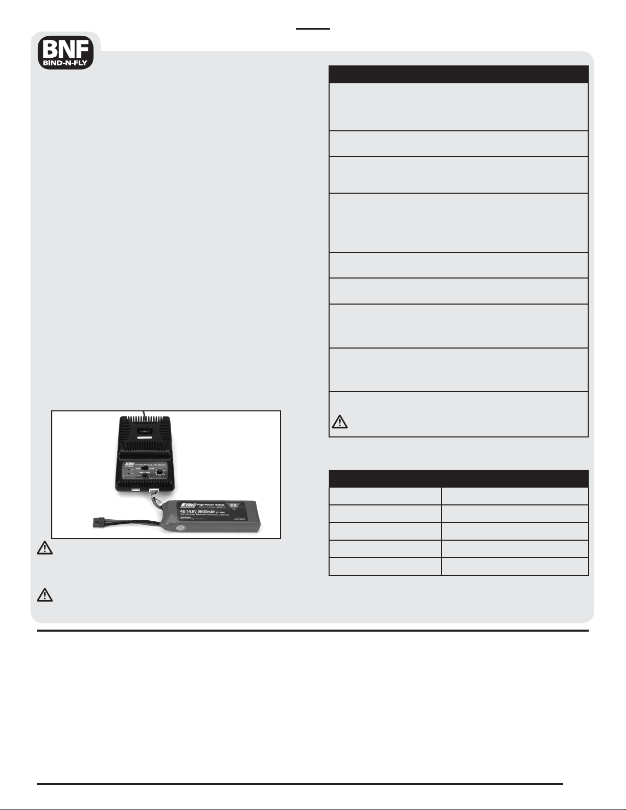
Charging the Flight Battery
Your E-flite Carbon-Z Yak 54 comes with a DC balancing
charger and 4S Li-Po battery. You must charge the
included Li-Po battery pack with a Li-Po specific charger
only (such as the included charger). Never leave the
battery and charger unattended during the charge
process. Failure to follow the instructions properly
could result in a fire. When charging, make certain
the battery is on a heat-resistant surface. Charge the
battery pack while you are assembling the aircraft. You
will need the flight battery to confirm proper aircraft
operation in future steps.
DC Li-Po Balancing Charger Features
• Charges 3-to 4-cell lithium polymer battery packs
• Variable charge rates from 500mAh to 3-amp
• Simple single push-button operation
• LED charge status indicator
• LED cell balance indicator
• Audible beeper indicates power and charge status
• 12V accessory outlet input cord
Specifications
• Input power: 12V DC, 3-amp
• Charges 3- to 4-cell Li-Po packs with minimum
capacity of 500mAh
4S 14.8V 2800mAh Li-Po Battery Pack
The E-flite 4S Li-Po battery pack features a balancing
lead that allows you to safely charge your battery pack
when used with the included E-flite Li-Po
balancing charger.
EN
The Battery Charging Process
1. Charge only batteries that are cool to the touch and
are not damaged. Look at the battery to make sure
it is not damaged e.g., swollen, bent, broken or
punctured.
2. Attach the input cord of the charger to the
appropriate power supply (12V accessory outlet).
3. When the Li-Po charger is correctly powered up,
there is an approximate 3-second delay, then an
audible “beep” and the green (ready) LED will flash.
4. Turn the control on the Amps selector so the arrow
points to the charging rate required for the Battery.
(See chart, for example the Yak 54 2800mAh Li-Po
battery will charge at 3.0 amps.) DO NOT change the
charge rate once the battery begins charging.
5. Move the cell selector switch to 3-cell or 4-cell for
your battery.
6. Connect the Balancing Lead of the Battery to the
3-cell (4 pins) or 4-cell (5 pins) Charger port.
7. The green and red LEDs may flash during the
charging process, when the charger is balancing
cells. Balancing prolongs the life of the battery.
8. When the battery is fully charged, an audible beep
will sound for about 3 seconds, and the green LED
will shine continuously.
9. Always unplug the battery from the charger
immediately upon completion of charging.
CAUTION: Overcharging a battery can cause a fire.
WARNING: Failure to use the proper charger for a
Li-Po battery can result in serious damage, and if left
charging long enough, will cause a fire. ALWAYS use
caution when charging Li-Po batteries.
WARNING: Selecting a charge rate higher than 1x
(one times) the battery capacity may cause a fire.
Low Voltage Cutoff (LVC)
When a Li-Po battery is discharged below 3V per
cell, it will not hold a charge. The Carbon-Z Yak 54
Electronic Speed Control protects the flight battery
from over-discharge using Low Voltage Cutoff (LVC).
Before the battery charge decreases too much, LVC
removes power from the motor. Power to the motor
pulses, showing that some battery power is reserved
for flight control and safe landing.
Battery Capacity Maximum Charge Rate
500-1000mAh 500mA
1000-1500mAh 1A
1500-2000mAh 1.5A
2000-2500mAh 2.0A
3000mAh + 3.0A
When the motor pulses, please land the aircraft
immediately and recharge the flight battery.
Disconnect and remove the Li-Po battery from the
aircraft after use to prevent trickle discharge. Fully
charge your Li-Po battery before storing it.
During storage make sure battery charge does not go
below 3V per cell.
Note: The speed control is programmed for 4S LVC.
5
Page 6
General Assembly and
Maintenance Tips
Note: This checklist is not a replacement for the
content included in this manual. Although you can use
it as a quick start guide, we strongly suggest reading
through this manual completely before proceeding.
EN
First Flight Preparation
Remove and inspect contents
Begin charging fl ight battery
Assemble Carbon-Z Yak 54
Install the landing gear
Install the stab
Install rudder and elevator
push rod
Install the wings
Install receiver
Connect servos to receiver or
Y-harness
Install fully charged battery
Bind the receiver to a
transmitter, if applicable
Perform the Control Direction
Test with the transmitter
Adjust fl ight controls and
transmitter
Adjust battery for center of
gravity (CG) see installing the
fl ight battery.
Perform a radio system
Range Check
Find a safe and open fl ying fi eld
Plan fl ight for fl ying fi eld
conditions
Activity BNF PNP
◆◆
◆◆
◆◆
◆◆
◆◆
◆◆
◆◆
◆
◆◆
◆◆
◆◆
◆◆
◆◆
◆◆
◆◆
◆◆
◆◆
Maintenance After Flying
Disconnect fl ight battery from
ESC (Required for Safety)
Turn off transmitter (Required
for Safety)
Remove fl ight battery
from aircraft
Recharge fl ight battery
Clean aircraft (wipe off dirt, etc.)
Repair or replace all
damaged parts
Carefully disassemble and
store aircraft
Store fl ight battery apart from
aircraft and monitor the
battery charge
Activity BNF PNP
◆◆
◆◆
◆◆
◆◆
◆◆
◆◆
◆◆
◆◆
Transmitter and Receiver Binding
Binding is connecting a transmitter to an aircraft
receiver wirelessly or electronically so the aircraft
receiver recognizes the transmitter GUID (Globally
Unique Identifier) code. Binding is necessary for
proper operation.
Note: The Carbon-Z Yak 54 BNF requires a DSM2 full
range (high power) transmitter. Any JR or Spektrum
DSM2 transmitter can bind to the Spektrum AR600
receiver. Due to the aerobatic nature of the Carbon-Z
Yak 54, we recommend using a transmitter with
adjustable exponential and dual rates. Please visit
www.bindnfly.com for a complete list of
compatible transmitters.
Note: When using a Futaba transmitter with a
Spektrum module,you may need to reverse the
throttle channel.
6
CAUTION: ALWAYS power on the transmitter
before connecting the flight battery to the aircraft
ESC. ALWAYS disconnect the flight battery from the
aircraft ESC before powering off the transmitter.
Additional Binding Information
Before each flight, power on the transmitter and wait
about 5 seconds before powering on the ESC. The
transmitter scans and secures two radio frequencies
for aircraft control. When the flight battery is
connected too quickly for the transmitter to make
frequency selection, the transmitter and receiver may
not connect. When there is no connection, leave the
transmitter powered on, disconnect the flight battery
then reconnect the flight battery to the receiver.
Page 7
EN
1. Read transmitter instructions for binding to a receiver (location of transmitter’s Bind control).
2. Make sure transmitter is powered o .
3. Install a bind plug in the receiver Batt/Bind port.
4. Connect the ight battery to the ESC.
5. Turn the ESC switch on to power the receiver. The receiver LED will begin to ash rapidly.
6. Power on the transmitter while holding the transmitter bind button or switch. Refer to your transmitter’s manual
for binding button or switch instructions.
7. The receiver light will go from ashing rapidly to ashing slowly. After 5–10 seconds the light will become solid
indicating the receiver is bound to the transmitter.
8. Remove the bind plug from the receiver.
9. Safely store the bind plug (some owners attach the bind plug to their transmitter using two-part loops and clips).
10. The receiver will keep the binding to the transmitter until a bind plug is put in the receiver Batt/Bind port.
* The throttle will not arm if the transmitter’s throttle control and throttle trim are not put at the lowest position.
If you encounter problems, obey binding instructions and refer to transmitter troubleshooting guide for other
instructions. If needed, contact the appropriate Horizon Product Support office.
Installing Landing Gear
Binding Procedure Reference Table
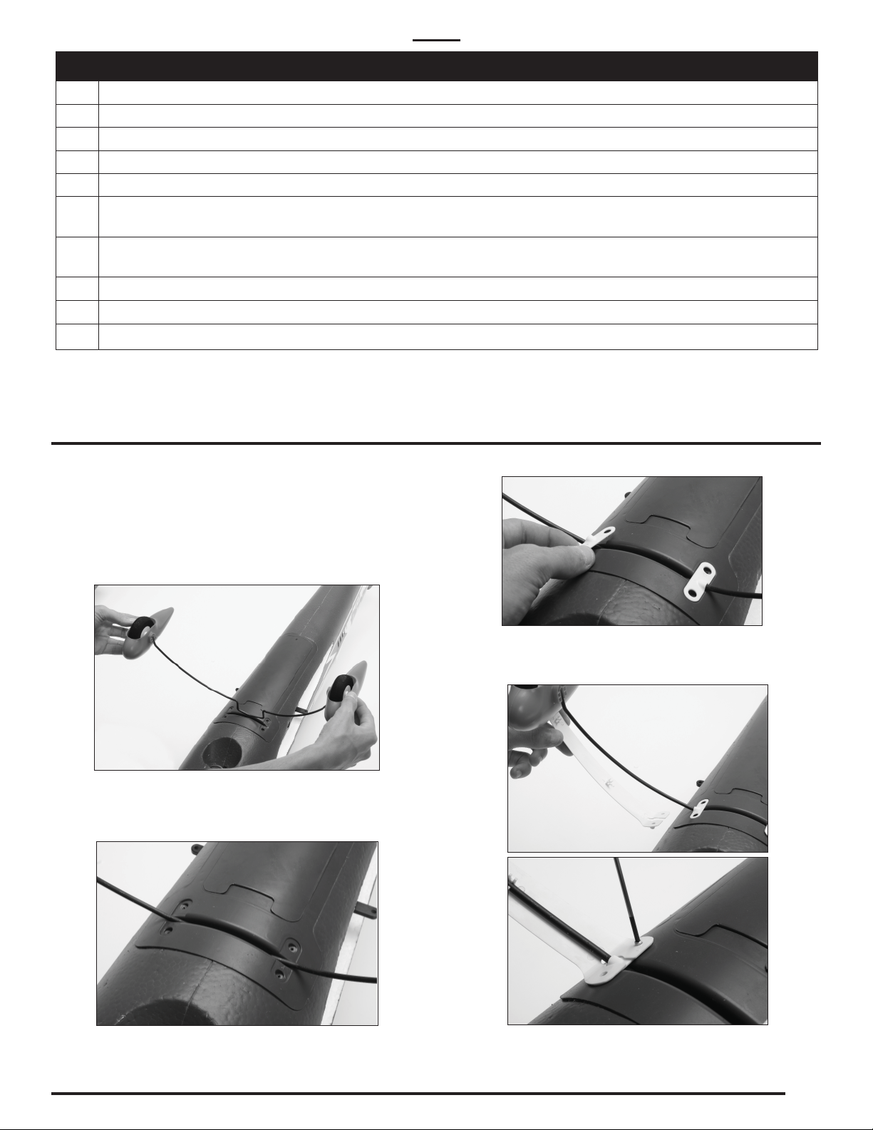
3. Install fairing plates.
Note: You may remove fairings for flying the
Carbon-Z Yak 54 from a rough runway.
1. Press together landing gear legs and put landing
gear support in slot in bottom of fuselage.
2. Release landing gear when support is fully
installed in the fuselage slot.
4. Install left (marked “L”) and right (marked “R”)
landing gear fairings on the landing gear supports
and fuselage using 4 small screws.
7
Page 8

EN
Installing Wings
1. Put the wing tube in the round hole in the wing
slot of the fuselage.
2. Put left wing on the wing tube.
3. Move the wing on the tube into the slot in the
fuselage while putting the aileron control
connector in the fuselage.
4. Secure left wing to fuselage using screws.
5. Install the right wing using the steps above.
6. Attach the 2 aileron connectors to the aileron
Y-harness in the fuselage.
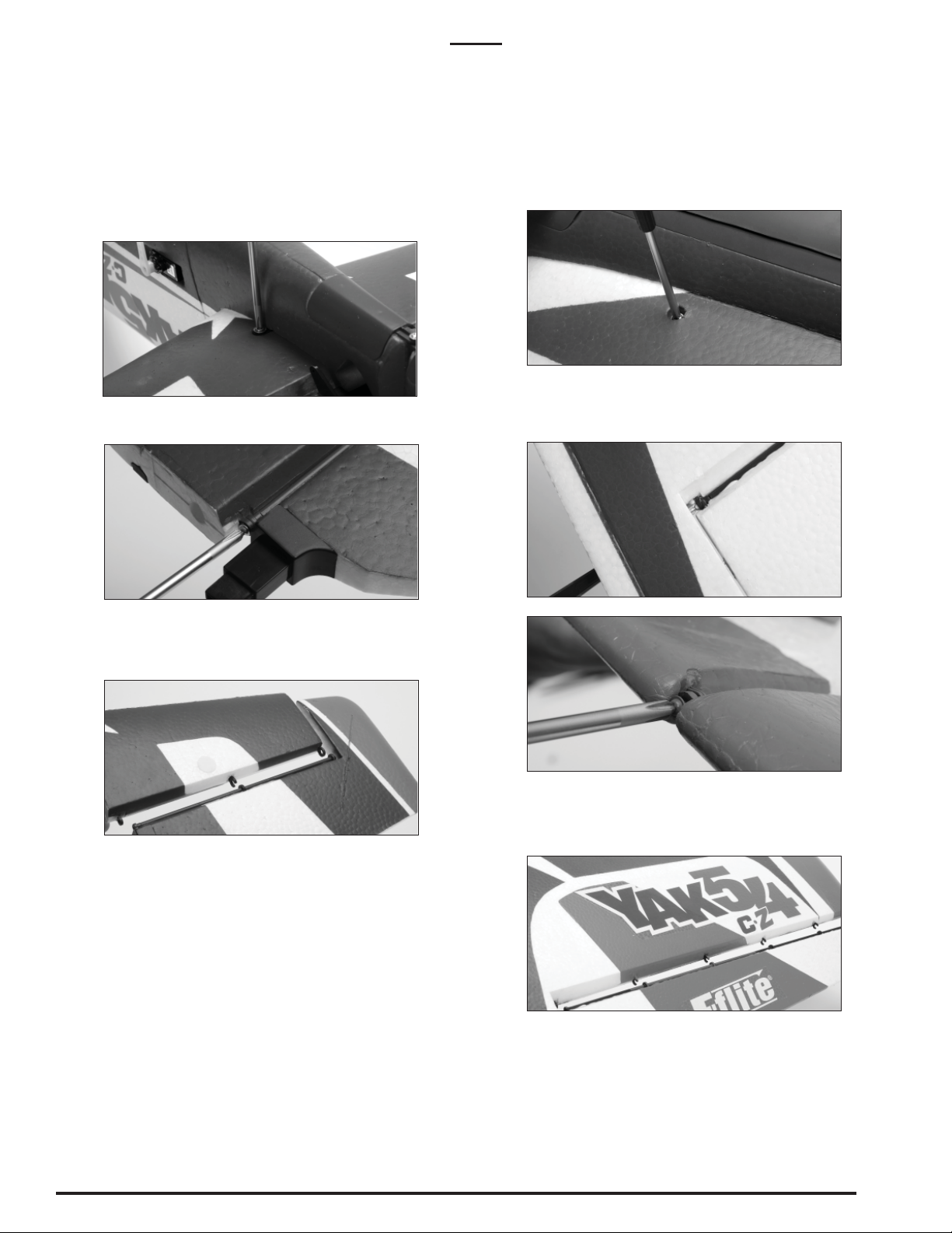
Installing Rudder
1. Attach the rudder to the hinge rod. Put the screw
in the bottom of the hinge rod.
Note: There is no difference between the 2 connections on the Y-harness. Left and right servo
lead connectors do not have to be connected to a
particular side of the Y-harness.
If using flaperon/dual aileron transmitter
programming, you can remove the Y-harness. The
aileron leads will connect to AILE and AUX1 when
using flaperon/dual aileron.
2. Put the rudder linkage clevis in the hole on the
control horn.
NOTICE: Do not tighten the screw too much. The
rudder will not move easily if the screw is tightened
too much.
8
Page 9

EN
Installing Horizontal Tail and
Pushrods on Control Horns
Installing the Horizontal Tail
1. Put the horizontal stabilizer tube in the round hole
located in the horizontal stabilizer slot of the
fuselage.
2. Slide the left horizontal stabilizer onto the
stabilizer tube.
3. Slide the right horizontal stabilizer onto the
stabilizer tube.
4. Secure each horizontal stabilizer with the included
machine screws.
Installing Pushrods on Control Horns
CAUTION: The installation positions of the
pushrods and clevises directly affect aircraft
response. When these are incorrectly connected for
the pilot’s skill level, unexpected aircraft response to
controls can result in unintended crash damage to
the aircraft.
Note: The elevator and rudder pushrods come with a
nylon clevis already installed and a 90˚ bend
already bent.
Elevator Pushrod Installation
1. Locate the 6 1/2-inch (165mm) pushrod.
2. Carefully spread the clevis and put the clevis pin
into the hole in the control horn.
Tip: You can thread the clevis in and out to shorten
or lengthen the pushrod. Make sure transmitter trims
and sub-trims are centered before making mechanical
adjustments.
3. Slide the 90° bend into the third hole from
the screw.
4. Snap the 90° pushrod keeper on the pushrod. This
holds the pushrod to the servo arm.
Rudder Pushrod Installation
1. Locate the 7 7/8-inch (200mm) rudder pushrod.
2. Carefully spread the clevis apart and slide the pin
into the control horn.
3. Slide the 90° bend of the pushrod into
the outermost hole on the servo arm.
4. Snap the 90˚ pushrod keeper on the pushrod. This
holds the pushrod to the servo arm.
Note: Make sure the elevator joiners interlock with
each other, allowing both elevators to move together.
Aileron RudderElevator
Arms
Note: Not to scale.
9
Page 10

EN
I
Installing the Flight Battery
Note: Before flying and after centering control
surfaces, rebind the aircraft so control surfaces are
neutral when you plug in the flight battery.
CAUTION: Install receiver and connect the speed
control into the throttle channel (for PNP) before
installing the flight battery.
1. Install the flight battery in the aircraft.
2. Secure the flight battery using the hook and
loop straps.
Adjusting Center of Gravity (CG) by Moving
the Battery
The CG location is 6-inches (153mm) forward from
trailing edge of the wing tip +/- 1/4inch (6.4mm). This
CG location has been determined with the E-flite
14.8V 2800mAh 30C Li-Po battery installed in the
middle of the cavity (see picture) and the aircraft
positioned upright.
Note: Due to the round wing tips, it is more accurate
to measure the CG from the trailing edge. If you
want a nose-heavy (forward) or tail-heavy (rear)
condition, move the battery forward or to the rear.
6 In
6
Control Surface Direction Test
Aircraft and transmitter binding should be done
before the control direction test. Move the controls
on the transmitter to make sure aircraft control
surfaces move correctly.
Controls in Reverse in Control Direction Test
If controls respond in the opposite direction reverse
the direction for operation of flight controls. Refer to
your transmitter’s instructions for changing direction
of transmitter flight controls.
Setting for Control Surface Travel
Adjust ATV/travel adjustment
on your transmitter until you
obtain the following control
surface travel. Do not adjust
dual rates until you have
correctly adjusted the total
travel:
Ailerons: 60 to 70mm left and
right (both ailerons), measured
at the aileron root.
Elevator: 48 to 50mm up
and down, measured at the
counterbalance leading edge.
Rudder: 60 to 65mm left
and right, measured at the
counterbalance leading edge.
For information on more
advanced programming, please visit
www.e-fliterc.com
Control Surface Travel
Exponential Settings
Following are Quique Somenzini’s dual rate and exponential settings
for intermediate flyers of the Carbon-Z Yak 54. The settings are based
on the ATV set in the previous step.
High rate Expo
Elev. 100% (or 48 mm to 50mm up and down) 50%
Ail. 100%
Rud. 100%
Low rate Expo
Elev. 22% (or 15mm up and down) 25%
Ail. 30% (or 30mm left and right both ailerons) 30%
Rud. 60%
Mix: Rudder to Elevator
Full left rudder -2% (up elevator)
Full right rudder -2% (up elevator)
Note: These control throws were developed by Quique Somenzini for
the best performance of the Carbon-Z Yak 54. The small amount of
elevator throw on low rate is capable of extreme aerobatics.
Note: only switch to high rate when the plane is flying at slow
speed. Never fly at high rate at full airspeed. This airplane is very
responsive and pilot can easily lose orientation. Get familiar with the
plane first and then try high rate.
Note: for take off and landings, low rate in all control surfaces is
strongly recommended.
For Quique’s advanced setup, visit www.e-fliterc.com.
(or 60 mm to 70 mm left and right both ailerons) 60%
(or 60 mm to 65mm left and right) 50%
(or 45mm left and right) 25%
10
Page 11
EN
Removing the Control Surfaces
To remove the control surfaces, follow the steps
listed below:
Elevator
1. Disconnect the clevis from the control horn.
2. Remove the machine screws located on the
bottom of the horizontal stabilizer. Then remove
the horizontal stabilizer from the fuselage.
3. Remove the screw located on the hinge line at the
root of the horizontal stabilizer.
Ailerons
1. Disconnect the ball-link from the control horn.
2. Remove the machine screw located on the bottom
of the wing. Then carefully remove the wing from
the fuselage.
Note: You will need to unplug the aileron servo lead
before removing the wing.
3. Remove the two screws located on the hinge line.
One is located at the wing tip and the other at
the root.
4. Carefully separate the elevator from the horizontal
stabilizer.
Note: The outer hinge is not open.
Note: To reinstall the elevator to the horizontal
stabilizer follow the steps listed above in reverse.
Rudder
Reverse the steps located in the “Installing Rudder”
section for rudder removal.
4. Carefully separate the aileron from the wing.
Note: To reinstall the aileron to the wing, follow the
steps listed above in reverse.
11
Page 12

EN
Removing Propeller Adapter,
Propeller and Spinner
Note: The information on this page is for
maintenance of the Yak 54. Spinner, propeller and
propeller adapter damage can result from
aircraft crashes.
CAUTION: DO NOT handle propeller parts while
the flight battery is connected to the ESC. Personal
injury could result.
1. Remove the screw in the spinner.
2. Remove the spinner cone.
3. Use an adjustable wrench to loosen and remove
the propeller nut.
4. Remove the propeller from the prop adapter collet.
5. Remove the spinner backplate from the prop
adapter collet.
6. Remove the swage plate from the prop
adapter collet.
Motor and ESC Removal
Note: The information on this page is for
maintenance of the Carbon-Z Yak 54. Damage
to these parts can result from aircraft crashes.
Installation of the motor is in reverse order of the
steps listed below. You must remove the propeller
and spinner from the motor (EFLM7300) before
removing the motor from the aircraft.
CAUTION: DO NOT handle the motor or ESC
while the flight battery is connected to the ESC.
Personal injury could result.
1. Remove the battery hatch from the fuselage.
2. Disconnect the 3 motor wires located on the
bottom of the fuselage near the ESC.
7. Remove the prop adapter collet from the
motor shaft.
3. Remove the 4 outermost screws on the “X”
mount, and slide the motor out of the nose.
12
Page 13

• Front view of screws on motor mount
4. To install the motor:
Slide the 4 motor wires through the guide holes and
slide the motor all the way into the nose.
EN
Note: When installing the new motor do not attach
the “X” mount until last. This will make connecting
the 3 motor wires much easier.
5. Plug the 3 motor wires into the ESC, making sure
of proper polarity.
Note: Wires are color-coordinated to prevent wrong
polarity connection.
7. Attach the “X” mount to the motor with the 4
machine screws provided with the mount.
Tip: Use threadlock on the 4 machine screws
mentioned in the above step. This will prevent
them from coming loose in flight.
8. Secure the motor to the fuselage by installing the
4 screws to the outer holes in the “X” mount.
9. Reinstall the prop and spinner by reversing the
steps in the Removing Propeller Adapter, Propeller
and Spinner section.
PNP Installation
Installing a Receiver
1. Install your full range receiver in the fuselage
using hook and loop tape or double-sided
servo tape.
2. Attach the elevator and rudder servo connectors to
the appropriate channels of the receiver.
3. Attach the aileron Y-harness to the aileron channel
of the receiver.
Range Check and Pre-Flying Tips
Range Check your Radio System
After final assembly, range check the radio system
with the Carbon-Z Yak 54. Refer to your specific
transmitter instruction manual for range test
information. It is helpful to have another person
assist with the range check and secure the airplane.
If assistance is not available, secure the tail of the
aircraft before increasing the throttle.
Before Each Flying Session
• Always make sure the dual rates switch is set to
LOW rates for takeoff. We recommend LOW rates
for your initial flights. The Carbon-Z Yak 54 is VERY
maneuverable on high rates and requires a lot of
experience to handle properly.
• It is recommended to set the timer for 5 minutes
before take off.
4. Attach the ESC connector to the throttle channel of
the receiver.
Battery Selection and Installation
• We recommend the E-flite 2800mAh 14.8V 30C
Li-Po battery (EFLB28004S30).
• If using another battery, the battery must be at
least a 30C 2800mAh battery.
• Your battery should be approximately the same
capacity, dimensions and weight as the E-flite
Li-Po battery to fit in the fuselage without changing
the center of gravity a large amount.
• Always make sure your Carbon-Z Yak 54 is
properly trimmed prior to each flight
• Always make sure the receiver, ESC, and battery
are secured in the fuselage.
• Perform a range check according to your
transmitter’s instructions prior to each flight.
• Always make sure that all controls function per the
transmitter input you give. This includes ailerons,
rudder, elevator and throttle.
• Always fully charge the transmitter batteries or
make sure your transmitter has fresh batteries
before you fly.
• Always make sure the servo reversing switches on
the transmitter are set correctly.
CAUTION: Always remove the flight battery from
the aircraft when you are done flying, or when you
are on the way to the flying field.
Flying Tips and Repairs
Flying
Always follow local ordinances when choosing a
location to fly. Choose a wide-open space for flying
your E-Flite Carbon-Z Yak 54 BNF or PNP. It is ideal for
you to fly at a sanctioned flying field, as the Carbon-Z
Yak 54 is capable of speeds exceeding 70 mph. If you
are not flying at an approved site, always avoid flying
near houses, trees, wires and buildings. You should
also be careful to avoid flying in areas where there
are many people, such as busy parks, schoolyards, or
soccer fields.
13
Page 14

EN
Note: The Carbon-Z Yak 54 is a high-performance
aircraft, designed to handle the stresses of highenergy aerobatic flight. Due to the construction of the
Carbon-Z Yak 54, the airframe is capable of handling
high G maneuvers.
Takeoff
Choose a large open area with a smooth surface for
takeoff. Confirm your transmitter dual rate switch is
set to LOW rates for takeoff. Point the nose of the
aircraft into the wind.
Landing
Set to Low Rate, start the landing approach by
reducing throttle to 1/4 or less to slow the aircraft. Fly
the aircraft down to about 1-2 feet above the runway.
Slowly reduce power until the throttle is in the off
position. Apply up elevator as the aircraft settles
to the runway. The Carbon-Z Yak 54 can do a main
landing gear landing, or two-point landing, where the
aircraft touches down on the main wheels first and
the tailwheel is off the ground. The Carbon-Z Yak 54
can also land in three-point attitude when all three
wheels touch the runway at the same time.
Repairs
Thanks to the construction of the Carbon-Z Yak 54,
repairs to the foam can be made using virtually any
adhesive (hot glue, regular CA, epoxy, etc). When
parts are not repairable, see the Replacement Parts
List for ordering by item number.
Note: The Carbon-Z Yak 54 can be taken apart and
put back in the box for storage or transportation.
2010 Official Academy of Model Aeronautics Safety Code
Effective January 1, 2010
GENERAL
1. A model aircraft shall be defi ned as a non-
human carrying device capable of sustained flight
in the atmosphere. It shall not exceed limitations
established in this code and is intended to be
used exclusively for recreational or
competition activity.
2. The maximum takeoff weight of a model aircraft,
including fuel, is 55 pounds, except for those fl
own under the AMA Experimental Aircraft Rules.
3. I will abide by this Safety Code and all rules
established for the flying site I use. I will not
willfully fly my model aircraft in a reckless and/or
dangerous manner.
4. I will not fl y my model aircraft in sanctioned
events, air shows, or model demonstrations until
it has been proven airworthy.
5. I will not fl y my model aircraft higher than
approximately 400 feet above ground level, when
within three (3) miles of an airport without
notifying the airport operator. I will yield the
right-of-way and avoid fl ying in the proximity of
full-scale aircraft, utilizing a spotter when
appropriate.
6. I will not fl y my model aircraft unless it is
identified with my name and address, or AMA
number, inside or affi xed to the outside of the
model aircraft. This does not apply to model
aircraft fl own indoors.
7. I will not operate model aircraft with metal-blade
propellers or with gaseous boosts (other than air),
nor will I operate model aircraft with fuels
containing tetranitromethane or hydrazine.
8. I will not operate model aircraft carrying
pyrotechnic devices which explode, burn, or
propel a projectile of any kind. Exceptions include
Free Flight fuses or devices that burn producing
smoke and are securely attached to the model
aircraft during flight. Rocket motors up to a
G-series size may be used, provided they remain
firmly attached to the model aircraft during flight.
Model rockets may be flown in accordance with
the National Model Rocketry Safety Code;
however, they may not be launched from model
aircraft. Officially designated AMA Air Show
Teams (AST) are authorized to use devices and
practices as defined within the Air Show Advisory
Committee Document.
9. I will not operate my model aircraft while under
the influence of alcohol or within eight (8) hours
of having consumed alcohol.
10. I will not operate my model aircraft while using
any drug which could adversely affect my ability
to safely control my model aircraft.
11. Children under six (6) years old are only allowed
on a flightline or in a fl ight area as a pilot or
while under fl ight instruction.
12. When and where required by rule, helmets must
be properly worn and fastened. They must be
OSHA, DOT, ANSI, SNELL or NOCSAE approved
or comply with comparable standards.
RADIO CONTROL
1. All model flying shall be conducted in a manner
to avoid over fl ight of unprotected people.
2. I will have completed a successful radio
equipment ground-range check before the first
flight of a new or repaired model aircraft.
3. I will not fly my model aircraft in the presence of
spectators until I become a profi cient flier, unless
I am assisted by an experienced pilot.
4. At all flying sites a line must be established, in
front of which all flying takes place. Only
personnel associated with flying the model
aircraft are allowed at or in front of the line. In the
case of airshows demonstrations straight line
must be established. An area away from the line
must be maintained for spectators. Intentional
flying behind the line is prohibited.
5. I will operate my model aircraft using only radio
control frequencies currently allowed by the
Federal Communications Commission (FCC).
Only individuals properly licensed by the FCC are
authorized to operate equipment on Amateur
Band frequencies.
14
Page 15

EN
FREE FLIGHT
1. I will not launch my model aircraft unless I am
at least 100 feet downwind of spectators and
automobile parking.
2. I will not fl y my model aircraft unless the launch
area is clear of all individuals except my
mechanic, offi cials, and other fl iers.
3. I will use an effective device to extinguish any
fuse on the model aircraft after the fuse has
completed its function.
CONTROL LINE
1. I will subject my complete control system
(including the safety thong where applicable) to
an inspection and pull test prior to flying. The
Troubleshooting Guide
Problem Possible Cause Solution
Aircraft will not respond to throttle
but responds to other controls
Extra propeller noise or extra
vibration
Reduced fl ight time or aircraft
underpowered
LED on receiver fl ashes quickly
with bind plug installed and
aircraft cannot be controlled by
transmitter
Control surface does not move,
or is slow to respond to control
inputs.
• ESC is not armed.
• Throttle channel is reversed
• Damaged spinner, propeller,
motor or motor mount
• Loose propeller and spinner parts
• Propeller installed backwards
• Flight battery charge is low
• Propeller installed backwards
• Flight battery damaged
• Transmitter too close to aircraft
• Transmitter bound to another
aircraft
• Batteries in transmitter low
• Control surface, control horn,
linkage or servo damage
• Wire damaged or connections
loose
pull test will be in accordance with the current
Competition Regulations for the applicable model
aircraft category. Model aircraft not fitting a
specific category shall use those pull-test
requirements as indicated for Control Line
Precision Aerobatics.
2. I will ensure that my flying area is clear of all
utility wires or poles and I will not fly a model
aircraft closer than 50 feet to any aboveground
electric utility lines.
3. I will ensure that my fl ying area is clear of all
nonessential participants and spectators before
permitting my engine to be started.
Please see your local or regional modeling
association’s guidelines for proper, safe operation of
your model aircraft.
• Lower throttle stick and throttle trim
to lowest settings.
• Reverse throttle channel on
transmitter
• Replace damaged parts
• Tighten parts for propeller adapter,
propeller and spinner
• Remove and install propeller
correctly
• Completely recharge fl ight battery
• Remove and install propeller
correctly
• Replace fl ight battery and obey
fl ight battery instructions
• Move powered transmitter a few
feet from aircraft, disconnect and
connect fl ight battery to aircraft and
re-bind.
• Bind transmitter to aircraft receiver
• Replace transmitter batteries
• Replace or repair damaged parts
and adjust controls
• Do a check of connections for
loose wiring
Controls reversed • Channels need to be reversed in
the transmitter
Motor loses power
Motor power pulses then motor
loses power
LED on receiver fl ashes slowly • Power lost to receiver • Check connection from ESC to
• Damage to motor, or battery
• Loss of power to aircraft
• ESC uses default soft Low Voltage
Cutoff (LVC)
• Do the Control Direction Test and
adjust controls for aircraft and
transmitter
• Do a check of batteries, transmitter,
receiver, ESC, motor and wiring for
damage (replace as needed)
• Land aircraft immediately and
Recharge fl ight battery
receiver
• Check servos for damage
• Check linkages for binding
15
Page 16

EN
Replacement Parts
Here is a list of replacement parts to repair or keep your Carbon-Z Yak 54 flying. These parts are available at your
local hobby shop or from Horizon Hobby (www.horizonhobby.com). Please try your local hobby shop first. By
supporting them, they will be there when you need them. Or you can call our consumer sales
line at 1 800 338 4639.
Number Description Notes
EFLA1060 60-Amp Pro Switch-Mode BEC Brushless ESC This is the ESC for the Carbon-Z Yak 54
EFLB28004S30 E-Flite 2800mAh 14.8V 30C Li-Po battery Recommended for size, weight and power in Carbon-Z Yak 54 BNF
EFLC3015 3- to 4-cell 12V DC Li-Po Battery Charger with
Balancer
EFLM7300 BL25 Brushless Outrunner Motor, 1000Kv
EFLM7301 Motor Shaft: BL25 Outrunner
EFLM7302 Prop Adapter: Carbon-Z Yak 54
EFLP12525E 12 x 5.25 Prop: Carbon-Z Yak 54
EFL1008001 Right Wing Panel: Carbon-Z Yak 54 Includes right wing panel, right aileron, hinges and control horn
EFL1008002 Left Wing Panel: Carbon-Z Yak 54 Includes left wing panel, left aileron, hinges and control horn
EFL1008003 Painted Fuselage: Carbon-Z Yak 54 Includes fuselage, vertical fi n, fi rewall, canopy, and landing
EFL1008004 Horizontal Stabilizer, Right: Carbon-Z Yak 54 Includes right horizontal stabilizer, right elevator, hinges and control
EFL1008005 Horizontal Stabilizer, Left: Carbon-Z Yak 54 Includes left horizontal stabilizer, left elevator, hinges
EFL1008006 Rudder: Carbon-Z Yak 54 Includes rudder, hinges and control horn
EFL1008007 Battery Hatch: Carbon-Z Yak 54 Includes the battery hatch and magnets
EFL1008008 Radio Hatch: Carbon-Z Yak 54 Includes the radio hatch
EFL1008009 Canopy: Carbon-Z Yak 54
EFL1008010 Wheel Pants: Carbon-Z Yak 54
EFL1008011 Pushrods with Clevis: Carbon-Z Yak 54
EFL1008012 Carbon Fiber Wing Tube: Carbon-Z Yak 54
EFL1008013 Carbon Fiber Stabilizer Tube: Carbon-Z Yak 54
EFL1008014 Pilot: Carbon-Z Yak 54
EFL1008015 Landing Gear Plates: Carbon-Z Yak 54
EFL1008016 Main Landing Gear Wire: Carbon-Z Yak 54
EFL1008017 Landing Gear Fairings: Carbon-Z Yak 54
EFL1008018 Main Wheels: Carbon-Z Yak 54
EFL1008019 Tail Wheel Set: Carbon-Z Yak 54
EFL1008020 Spinner: Carbon-Z Yak 54
EFL1008021 Servo Arm: Carbon-Z Yak 54
EFL1008022 Decal Sheet: Carbon-Z Yak 54
EFL1008023 Servo Extension Set: Carbon-Z Yak 54 Includes servo extensions for ailerons, elevator, rudder and ESC
EFL1008024 Motor Mount with Screws: Carbon-Z Yak 54 Includes motor mount, motor screws and fi rewall screws
EFL1008025 Screw Set: Carbon-Z Yak 54 Includes all screws for the airframe. Individual parts do not include
Note: When replacing servos, we recommend tying a string to the servo lead before removing the servo.
This allows you to easily reinstall the servo and lead.
This is the charger included in the Carbon-Z Yak 54 BNF
gear mount
horns
screws except where noted.
16
Page 17

Warranty and Repair Policy
EN
Warranty Period
Exclusive Warranty- Horizon Hobby, Inc., (Horizon)
warranties that the Products purchased (the “Product”)
will be free from defects in materials and workmanship
at the date of purchase by the Purchaser.
Limited Warranty
Horizon reserves the right to change or modify this
warranty without notice and disclaims all other
warranties, express or implied.
(a) This warranty is limited to the original Purchaser
(“Purchaser”) and is not transferable. REPAIR OR
REPLACEMENT AS PROVIDED UNDER THIS
WARRANTY IS THE EXCLUSIVE REMEDY OF THE
PURCHASER. This warranty covers only those
Products purchased from an authorized Horizon
dealer. Third party transactions are not covered by
this warranty. Proof of purchase is required for all
warranty claims.
(b) Limitations- HORIZON MAKES NO WARRANTY OR
REPRESENTATION, EXPRESS OR IMPLIED, ABOUT
NON-INFRINGEMENT, MERCHANTABILITY OR
FITNESS FOR A PARTICULAR PURPOSE OF THE
PRODUCT. THE PURCHASER ACKNOWLEDGES THAT
THEY ALONE HAVE DETERMINED THAT THE
PRODUCT WILL SUITABLY MEET THE REQUIRE-
MENTS OF THE PURCHASER’S INTENDED USE.
(c) Purchaser Remedy- Horizon’s sole obligation her
under shall be that Horizon will, at its option, (i)
repair or (ii) replace, any Product determined by
Horizon to be defective. In the event of a defect,
these are the Purchaser’s exclusive remedies
Horizon reserves the right to inspect any and all
equipment involved in a warranty claim. Repair
or replacement decisions are at the sole discretion
of Horizon. This warranty does not cover cosmetic
damage or damage due to acts of God, accident,
misuse, abuse, negligence, commercial use, or
modifi cation of or to any part of the Product.
This warranty does not cover damage due to improper
installation, operation, maintenance, or attempted
repair by anyone other than Horizon. Return of any
Product by Purchaser must be approved in writing by
Horizon before shipment.
Damage Limits
HORIZON SHALL NOT BE LIABLE FOR SPECIAL,
INDIRECT OR CONSEQUENTIAL DAMAGES, LOSS
OF PROFITS OR PRODUCTION OR COMMERCIAL
LOSS IN ANY WAY CONNECTED WITH THE PRODUCT,
WHETHER SUCH CLAIM IS BASED IN CONTRACT,
WARRANTY, NEGLIGENCE, OR STRICT LIABILITY.
Further, in no event shall the liability of Horizon exceed
the individual price of the Product on which liability is
asserted. As Horizon has no control over use, setup,
fi nal assembly, modifi cation or misuse, no liability
shall be assumed nor accepted for any resulting damage or injury. By the act of use, setup or assembly, the
user accepts all resulting liability.
If you as the Purchaser or user are not prepared to
accept the liability associated with the use of this
Product, you are advised to return this Product immediately in new and unused condition to the place
of purchase.
Law: These Terms are governed by Illinois law (without
regard to confl ict of law principals).
Warranty Services
Questions, Assistance, and Repairs
Your local hobby store and/or place of purchase cannot
provide warranty support or repair. Once assembly,
setup or use of the Product has been started, you must
contact Horizon directly. This will enable Horizon to
better answer your questions and service you in the
event that you may need any assistance. For questions
or assistance, please direct your email to productsupport@horizonhobby.com, or call 877.504.0233 toll free
to speak to a Product Support representative. You may
also find information on our website at www.horizonhobby.com.
Inspection or Repairs
If this Product needs to be inspected or repaired,
please use the Horizon Online Repair Request submission process found on our website or call Horizon
to obtain a Return Merchandise Authorization (RMA)
number. Pack the Product securely using a shipping carton. Please note that original boxes may be
included, but are not designed to withstand the rigors
of shipping without additional protection. Ship via a
carrier that provides tracking and insurance for lost
or damaged parcels, as Horizon is not responsible for
merchandise until it arrives and is accepted at our facility. An Online Repair Request is available at www.horizonhobby.com http://www.horizonhobby.com under the
Repairs tab. If you do not have internet access, please
contact Horizon Product Support to obtain a RMA number along with instructions for submitting your product
for repair. When calling Horizon, you will be asked to
provide your complete name, street address, email
address and phone number where you can be reached
during business hours. When sending product into
Horizon, please include your RMA number, a list of the
included items, and a brief summary of the problem. A
copy of your original sales receipt must be included for
warranty consideration. Be sure your name, address,
and RMA number are clearly written on the outside of
the shipping carton.
Notice: Do not ship batteries to Horizon. If you have
any issue with a battery, please contact the appropriate Horizon Product Support office.
Warranty Inspection and Repairs
To receive warranty service, you must include your
original sales receipt verifying the proof-of-purchase
date. Provided warranty conditions have been met, your
Product will be repaired or replaced free of charge. Repair
or replacement decisions are at the sole discretion of
Horizon Hobby.
Non-Warranty Repairs
Should your repair not be covered by warranty the
repair will be completed and payment will be required
without notification or estimate of the expense unless
the expense exceeds 50% of the retail purchase cost.
By submitting the item for repair you are agreeing to
payment of the repair without notification. Repair estimates are available upon request. You must include
this request with your repair. Non-warranty repair estimates will be billed a minimum of ½ hour of labor. In
addition you will be billed for return freight. Horizon
accepts money orders and cashiers checks, as well
as Visa, MasterCard, American Express, and Discover
cards. By submitting any item to Horizon for inspection or repair, you are agreeing to Horizon’s Terms and
Conditions found on our website under the
Repairs tab.
17
Page 18

Contact Information
EN
Country of
Purchase
United States
of America
United Kingdom Horizon Hobby Limited
Germany
France Horizon Hobby SAS
Horizon Hobby Address Phone Number / Email Address
Horizon Service Center
(Electronics and
engines)
Horizon Product
Support (All other
products)
Horizon Technischer
Service
4105 Fieldstone Rd
Champaign, Illinois
61822 USA
4105 Fieldstone Rd
Champaign, Illinois
61822 USA
Units 1-4 Ployters Rd
Staple Tye
Harlow, Essex
CM18 7NS
United Kingdom
Hamburger Str. 10
25335 Elmshorn
Germany
14 Rue Gustave Eiffel
Zone d’Activité du Réveil
Matin
91230 Montgeron
Compliance Information for the European Union
877-504-0233
Online Repair Request visit:
www.horizonhobby.com/repairs
877-504-0233
productsupport@horizonhobby.com
+44 (0) 1279 641 097
sales@horizonhobby.co.uk
+49 4121 46199 66
service@horizonhobby.de
+33 (0) 1 60 47 44 70
infofrance@horizonhobby.com
Declaration of Conformity
(in accordance with ISO/IEC 17050-1)
No. HH2010080903
Product(s): Carbon-Z Yak 54 BNF/PNP
Item Number(s): EFL10080/EFL10075
Equipment class: 1
The object of declaration described above is in conformity with the requirements of the specifications listed
below, following the provisions of the European R&TTE directive 1999/5/EC:
EN 301 489-1, 301 489-17 General EMC requirements
European EMC Directive 2004/108/EC:
EN55022 Radio disturbance characteristics
EN55024 Immunity characteristics
Signed for and on behalf of:
Horizon Hobby, Inc.
Champaign, IL USA
Aug. 09, 2010
Steven A. Hall
Vice President
International Operations and
Risk Management
Horizon Hobby, Inc.
Instructions for disposal of WEEE by users in the European Union
This product must not be disposed of with other waste. Instead, it is the user’s responsibility to dispose
of their waste equipment by handing it over to a designated collections point for the recycling of waste
electrical and electronic equipment. The separate collection and recycling of your waste equipment at
the time of disposal will help to conserve natural resources and ensure that it is recycled in a manner
that protects human health and the environment. For more information about where you can drop
off your waste equipment for recycling, please contact your local city office, your household waste
disposal service or where you purchased the product.
18
Page 19

E-Flite® products are distributed exclusively by Horizon Hobby, Inc.
The Spektrum trademark is used with permission of Bachmann Industries, Inc.
E-flite, Carbon-Z, DSM2, Bind-N-Fly and Plug-N-Play are trademarks or registered trademarks of Horizon Hobby, Inc.
Created 9/10 27300
© 2010 Horizon Hobby, Inc.
Patents Pending
 Loading...