

Page 1
TM
Carbon-ZTM Scimitar
Instruction Manual - Bedienungsanleitung - Manuel d’utilisation - Manuale di Istruzioni
Page 2
EN
NOTICE
All instructions, warranties and other collateral documents are subject to change at the sole discretion of Horizon Hobby, Inc. For up-to-date product
literature, visit www.horizonhobby.com and click on the support tab for this product.
Meaning of Special Language:
The following terms are used throughout the product literature to indicate various levels of potential harm when operating this product:
NOTICE: Procedures, which if not properly followed, create a possibility of physical property damage AND little or no possibility of injury.
CAUTION: Procedures, which if not properly followed, create the probability of physical property damage AND a possibility of serious injury.
WARNING: Procedures, which if not properly followed, create the probability of property damage, collateral damage, and serious injury OR create a high
probability of superfi cial injury.
WARNING: Read the ENTIRE instruction manual to become familiar with the features of the product before operating. Failure to operate the product
correctly can result in damage to the product, personal property and cause serious injury.
This is a sophisticated hobby product. It must be operated with caution and common sense and requires some basic mechanical ability. Failure to operate this
Product in a safe and responsible manner could result in injury or damage to the product or other property. This product is not intended for use by children
without direct adult supervision. Do not attempt disassembly, use with incompatible components or augment product in any way without the approval of Horizon
Hobby, Inc. This manual contains instructions for safety, operation and maintenance. It is essential to read and follow all the instructions and warnings in the
manual, prior to assembly, setup or use, in order to operate correctly and avoid damage or serious injury.
Additional Safety Precautions and Warnings
As the user of this product, you are solely responsible for operating in a manner that does not endanger yourself and others or result in damage to the product or
the property of others.
Age Recommendation: Not for children under 14 years. This is not a toy.
• This model is controlled by a radio signal subject to interference from many sources outside your control. Interference can cause momentary loss of control, so
it is advisable to always keep a safe distance in all directions around your model as this margin will help avoid collisions or injury.
• Always operate your model in open spaces away from full-size vehicles, traffi c and people.
• Always carefully follow the directions and warnings for this and any optional support equipment (chargers, rechargeable battery packs, etc.).
• Always keep all chemicals, small parts and anything electrical out of the reach of children.
• Always avoid water exposure to all equipment not specifi cally designed and protected for this purpose. Moisture causes damage to electronics.
• Never place any portion of the model in your mouth as it could cause serious injury or even death.
• Never operate your model with low transmitter batteries.
Battery Warnings
The Battery Charger included with your aircraft is designed to safely charge the Li-Po battery.
CAUTION: All instructions and warnings must be followed exactly. Mishandling of Li-Po batteries can result in a fi re, personal injury, and/or property damage.
• By handling, charging or using the included Li-Po battery, you assume all
risks associated with lithium batteries.
• If at any time the battery begins to balloon or swell, discontinue use imme-
diately. If charging or discharging, discontinue and disconnect. Continuing
to use, charge or discharge a battery that is ballooning or swelling can
result in fi re.
• Always store the battery at room temperature in a dry area for best results.
• Always transport or temporarily store the battery in a temperature range of
40–120º F. Do not store battery or model in a car or direct sunlight. If stored
in a hot car, the battery can be damaged or even catch fi re.
• NEVER USE A Ni-Cd OR Ni-MH CHARGER. Failure to charge the battery with
a compatible charger may cause fi re resulting in personal injury and/or
property damage.
• Never discharge Li-Po cells to below 3V under load.
• Never cover warning labels with hook and loop strips.
• Never leave charging batteries unattended.
• Never charge batteries outside safe temperature range.
• Never charge damaged batteries.
2
Page 3
Welcome to the cutting edge of electric fl ight! Your E-fl ite® Carbon-Z™ Scimitar™ aircraft is a quantum leap in tailless swept wing design that combines patentpending Carbon-Z construction with the latest in high-output brushless motor and vector–thrust propeller engineering. The speed and maneuverability this makes
possible is nothing short of spectacular. Read this manual thoroughly before taking your fi rst fl ight. The Carbon-Z Scimitar can cover a lot of ground in a hurry. The
better understanding you have of its performance and systems before your fi rst fl ight, the better that fl ight, and every one after, will be.
3 X 14mm
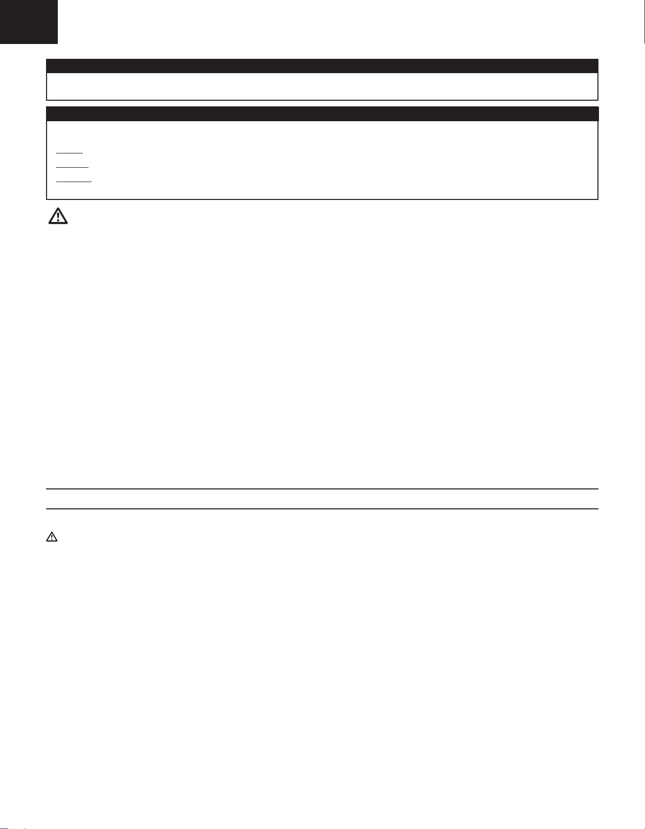
Includes:
EN
3 X 12mm
2 X 14mm
2.5 X 10mm
2.5 X 14mm
1.7 X 8mm
3 X 8mm
Table of Contents Specifi cations
Specifi cations ............................3
Charging the Flight Battery ........4
Low Voltage Cutoff (LVC) ............4
Transmitter and Receiver
Binding ......................................5
Installing Battery .......................5
Before Flight ..............................6
Installing a Receiver ...................6
Battery Selection
and Installation ..........................6
Fixed Landing Gear Installation ..7
Installing Optional Retractable
Landing Gear .............................8
Installing Optional Retractable
Landing Gear (Continued) ...........9
Installing Wings and
Vertical Fins ............................10
Balancing the Propeller ............11
Installing the Propeller .............11
Opening the Fuselage ..............12
Installing the Vectored
Thrust Lock .............................12
Control Centering .....................13
Adjusting a Clevis or Ball link ...13
Factory Settings .......................14
Transmitter Setup ....................14
Model Setup-Control Throws ....15
Center of Gravity (CG) ..............16
Control Direction Test ...............16
Prefl ight Checklist ....................17
Flying Tips ...............................17
Post Flight Checklist ................17
Fuselage Nose Service .............18
Control Surface Service ...........18
Servo Service ..........................19
Sub-Fin Service .......................20
Motor and Vectored-Thrust
Service ....................................20
Troubleshooting Guide .............21
AMA National Model Aircraft
Safety Code .............................22
Limited Warranty .....................23
Contact Information .................24
Compliance Information for
the European Union .................24
Parts Contact Information ........91
Replacement Parts ...................92
Optional Parts ..........................93
35.4 in (900mm)
32-size BL outrunner; 1010Kv
EFL 60A Pro Switch Mode BEC
brushless ESC
(5) Digital high-speed servo
(1) Digital high-speed/power
metal gear mini servo
Receiver:
6-channel Sport DSMX® Receiver
Battery:
Battery Charger: EFL 3–4 cell
variable rate DC Li-PO balancing
fast charger
Required Transmitter:
Full-Range 6-channel aircraft
transmitter with adjustable D/R
and Expo
42.5 in (1080mm)
3 X 12mm
2.5 X 14mm
Spektrum™ AR600
3200mAh 4S 30C Li-Po
Bind-N-Fly®
Aircraft
Installed Installed
Installed Installed
Installed Installed
Installed
Included
DSM2™/
DSMX®
Needed
Plug-N-Play
Aircraft
Needed to
Complete
Needed to
Complete
Needed to
Complete
565 sq inch
(31.91 sq dm)
3.63 lb (1.65 kg)
4.40 lb (2.00 kg)
®
To register your product online, visit www.e-fl iterc.com
3
Page 4
EN
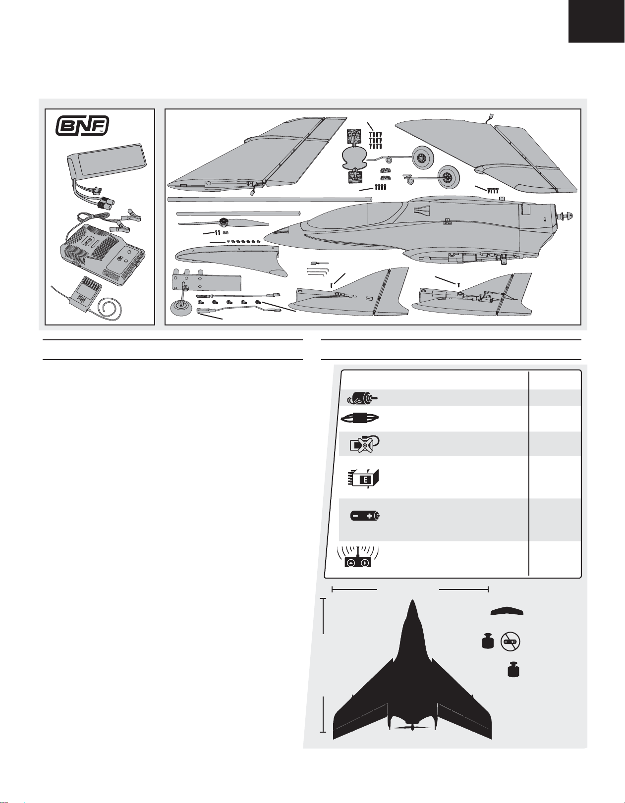
Charging the Flight Battery
Your E-fl ite Carbon-Z Scimitar comes with a DC balancing charger and 4S
Li-Po battery. You must charge the included Li-Po battery pack with a Li-Po
specifi c charger only (such as the included charger). Never leave the battery
and charger unattended during the charge process. Failure to follow the
instructions properly could result in a fi re. When charging, ensure the battery
is on a heat-resistant surface. Charge the battery pack while you are assembling the aircraft. You will need the fl ight battery to confi rm proper aircraft
operation in future steps.
DC Li-Po Balancing Charger Features
• Charges 3- to 4-cell lithium polymer battery packs
• Variable charge rates from 500mAh to 3-amp
• Simple single push-button operation
• LED charge status indicator
• LED cell balance indicator
• Audible beeper indicates power and charge status
• 12V accessory outlet input cord
Specifi cations
• Input power: 12V DC, 3-amp
• Charges 3- to 4-cell Li-Po packs with minimum
capacity of 500mAh
E-fl ite 4S 14.8V 3200mAh 30C Li-Po Battery Pack (EFLB32004S30)
The E-fl ite
allows you to safely charge your battery pack when used with the
included E-fl ite Li-Po balancing charger.
port of your charger prior to charging.
®
4S Li-Po battery pack features a balancing lead that
CAUTION: The balance connector must be inserted into the correct
The Battery Charging Process
1. Charge only batteries that are cool to the touch and are not damaged. Look at the battery to make sure it is not damaged e.g., swollen, bent, broken
or punctured.
2. Attach the input cord of the charger to the appropriate power supply (12V accessory outlet).
3. When the Li-Po charger is correctly powered up, there will be an approximate 3-second delay, then an audible “beep” and the green (ready) LED will fl ash.
4. Turn the control on the Amps selector so the arrow points to the charging rate required for the battery (the Scimitar 3200mAh Li-Po battery will charge at
3.0 amps). DO NOT change the charge rate once the battery begins charging.
5. Move the cell selector switch to 4-cell for your battery.
6. Connect the balancing lead of the battery to the 4-cell (5 pin) charger port and press the Start button to begin battery charging.
7. The green and red LEDs may fl ash during the charging process when the charger is balancing cells. Balancing prolongs the life of the battery.
8. When the battery is fully charged, a beep will sound for about 3 seconds and the green LED will shine continuously. Attempting to charge an over-discharged battery will cause the charger to repeatedly fl ash and beep, indicating an error has occurred.
9. Always unplug the battery from the charger immediately upon completion of charging.
battery. Failure to do so could result in fi re causing injury or property
damage.
CAUTION: Overcharging a battery can cause a fi re.
CAUTION: Only use a charger specifi cally designed to charge a Li-Po
CAUTION: Never exceed the recommended charge rate.
NOTICE: If using a battery other than the included Li-Po battery, refer to your
battery manufacturer’s instructions for charging.
Low Voltage Cutoff (LVC)
When a Li-Po battery is discharged below 3V per cell, it will not hold a charge.
The ESC protects the fl ight battery from over-discharge using Low Voltage
Cutoff (LVC). Before the battery charge decreases too much, LVC removes
power supplied to the motor. Power to the motor pulses, showing that some
battery power is reserved for fl ight control and safe landing.
When the motor pulses, land the aircraft immediately and recharge the
fl ight battery. Disconnect and remove the Li-Po battery from the aircraft after
use to prevent trickle discharge. Fully charge your Li-Po battery before storing
it. During storage, make sure the battery charge does not fall below 3V per cell.
4
Page 5

Transmitter and Receiver Binding
BIND
/DATA
THRO
AIL
E
ELEV
RUDD
GEAR
AUX
1
2.4GHz DSM® TECHNOLOGY
6CH SPORT RECEIVER 2048
EN
Binding is the process of programming the receiver of the control unit to recognize the GUID (Globally Unique Identifi er) code of a single specifi c transmitter. You
need to ‘bind’ your chosen Spektrum
™
DSM2™/DSMX® technology equipped aircraft transmitter to the receiver for proper operation.
Please visit www.bindnfl y.com for a complete list of compatible transmitters.
NOTICE: When using a Futaba transmitter with a Spektrum DSM® module, you must reverse the
BIND PLUG
throttle channel.
Binding Procedure Reference Table
Set up the transmitter for delta wing elevons before binding.
1. Read the transmitter instructions for binding to a receiver (location of transmitter’s Bind control).
2. Make sure the transmitter is powered off.
3. Move the transmitter controls to neutral (fl ight controls: rudder, elevators and ailerons) and to low
positions (throttle, throttle trim).*
4. Install a bind plug in the receiver bind port extension.
5. Connect the fl ight battery to the ESC.
6. Power on the ESC switch. The receiver LED will begin to fl ash rapidly.
Before binding:
1. Choose a blank model memory
with only default (zero) settings
(including trim and sub-trim).
2. Choose Wing Type as Delta
Wing or Elevons.
3. Set servo reversing (as recommended in the “Transmitter
Setup” section).
7. Power on the transmitter while holding the transmitter bind button or switch. Refer to your
transmitter’s manual for binding button or switch instructions.
8. When the receiver binds to the transmitter, the light on the receiver will be solid and the ESC will
produce a series of sounds. A long tone followed by three short tones confi rm that the LVC is set for
the ESC.
9. Remove the bind plug from the bind port extension.
10. Safely store the bind plug (some owners attach the bind plug to their transmitter using two-part
loops and clips).
11. The receiver should retain the binding instructions received from the transmitter until another binding is done.
* The throttle will not arm if the transmitter’s throttle control is not put at the lowest position. If you encounter problems, follow binding instructions and refer
to the transmitter troubleshooting guide for other instructions. If needed, contact the appropriate Horizon Product Support offi ce.
Installing Battery
1. Lift the front edge of the canopy (A) and pull the canopy forward and up
from the fuselage.
2. Install the included fl ight battery (B) all the way to the front of the
battery tray.
3. Connect the battery connector to the ESC connector.
4. Make sure the battery is secure in the battery compartment using hook
and loop straps (C).
5. Align the canopy pins with the two holes in the fuselage and install the
canopy so the magnets on the front of the canopy and fuselage meet.
Disassemble the model in reverse order.
CAUTION: Always disconnect the Li-Po battery from the aircraft
receiver when not fl ying to avoid over-discharging the battery. Batteries
discharged to a voltage lower than the lowest approved voltage may become
damaged, resulting in loss of performance and potential fi re when batteries
are charged.
B
C
A
CAUTION: Always keep hands away from the propeller. When armed,
the motor will turn the propeller in response to any throttle movement.
5
Page 6
EN
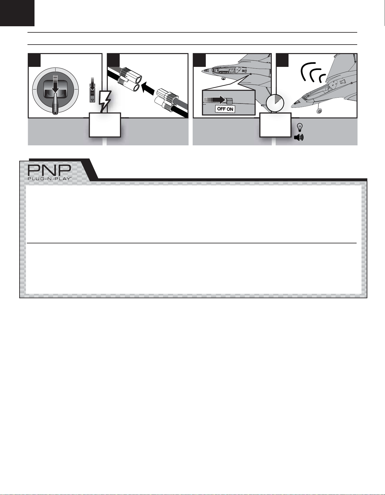
Before Flight
1 3 42
• Lower throttle and
throttle trim to
lowest settings.
Power on
Transmitter
• Connect battery to ESC.
Installing a Receiver
1. Install your full-range receiver in the fuselage using hook and loop tape or
double-sided servo tape.
2. Attach the right aileron to the elevator channel of your receiver. Attach the
left aileron to the aileron channel of your receiver.
3. Attach the Gear to channel 5.
4. Attach the Vector Thrust (VT) to AUX 1.
Battery Selection and Installation
1. We recommend the E-fl ite 3200mAh 4S 14.8V 30C Li-Po Battery
(EFLB32004S30).
TIP: To fi nd the correct CG, start by installing the 3200mAh battery all the way
to the front of the battery cavity, then adjust as needed until the desired CG is
achieved.
• Power on ESC switch.
5. You will also need to activate the delta wing/elevon confi guration of your
transmitter.
For specifi c setups for JR®/Spektrum 6+ channel transmitters, see the
“Transmitter Setup or Model Setup” sections in this manual.
6. Attach the ESC connector to the throttle channel of your receiver.
2. If using another battery, the battery must be at least a 30C 3200mAh
battery.
3. Your battery should be approximately the same capacity, dimensions and
weight as the E-fl ite Li-Po battery.
Wait 5
seconds
Continuous LED
Series of tones
66
Page 7
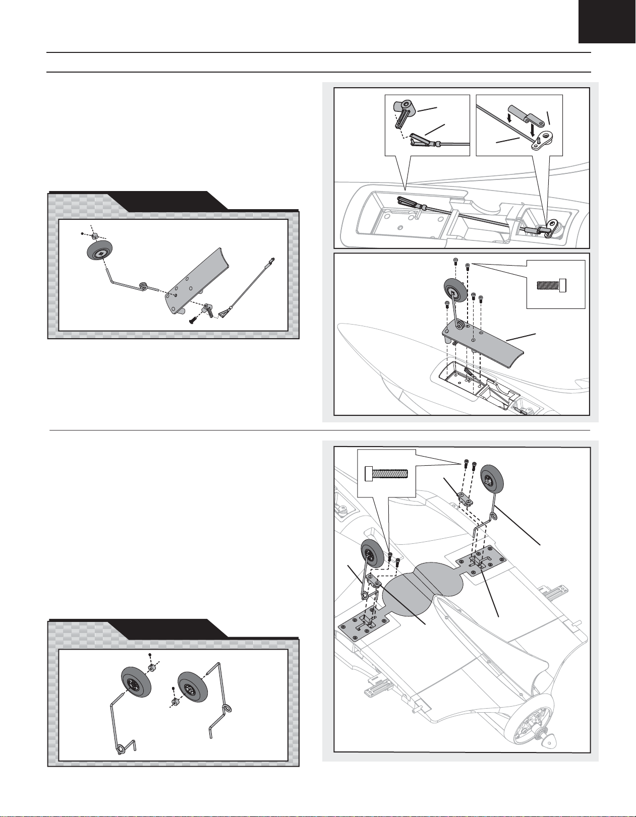
Fixed Landing Gear Installation
Installing Nose Gear
EN
1. Connect the linkage (A) to the steering servo arm (B). Always ensure
the steering linkage clevis is adjusted correctly to make the model steer
straight when the rudder control is at neutral.
2. Connect the clevis (C) to the arm of the nose gear (D).
3. Install the nose gear plate (E) on the fuselage using fi ve screws (F).
NOSE GEAR
PARTS EXPLOSION
D
B
C
A
F
3 X 8mm (5)
E
Installing Main Gear
1. Install the left and right gear struts (A and B, respectively) into the rear
gear plate (C). Please refer to the below illustration (Main Gear Parts
Explosion) to determine the proper orientation of the left and right struts.
2. Install the left and right strut cover plates (D and E, respectively) using
four screws (F).
3. Apply a small amount of threadlock to the wheel axle, collar and
screw in the collar.
Disassemble the model in reverse order.
The difference in length of the gear struts between the fi xed gear and optional
electric retract struts serve different purposes. The longer struts of the fi xed
gear give more ground clearance for the aircraft to operate on rougher
grass runways.
MAIN GEAR
PARTS EXPLOSION
A
F
3 X 12mm (4)
E
B
D
C
77
Page 8
EN
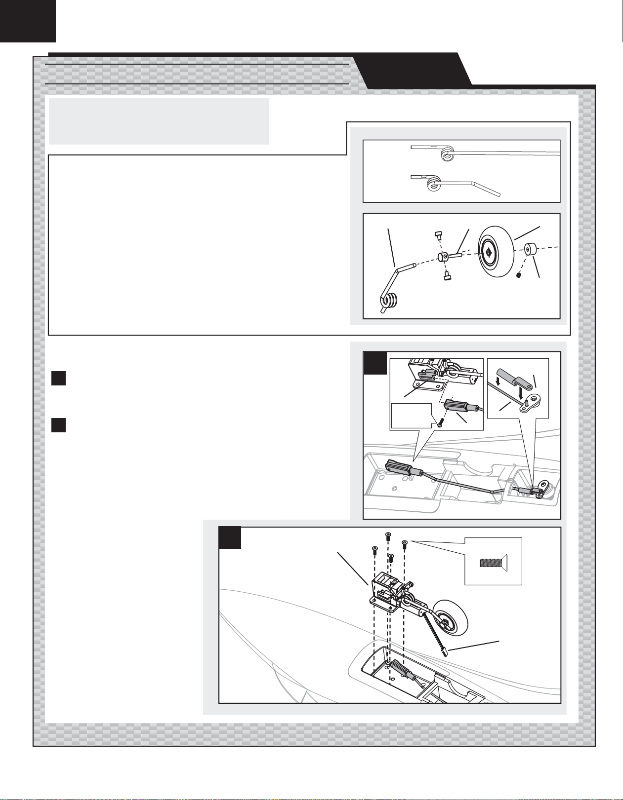
Installing Optional Retractable Landing Gear
This equipment is sold separately:
• 10- to 15-Size Tricycle Electric Retracts (EFLG110)
• Nose gear strut (EFL1018017)
Changing Stock Scimitar Nose Strut (EFL1018017) to Retractable Nose Gear
Use of the nose gear strut included with the electric retracts does not let the nose gear
retract into the fuselage well.
1. Replace the nose gear strut (A) (included with the electric retracts) with the nose
gear strut (B) designed for the Scimitar (EFL1018017) (sold separately). The spring
is under tension on the nose strut mount. Carefully install the new strut so the spring
stays on the nose strut mount.
2. Install the shaft (C), in the Scimitar nose wheel (D) and collar (E) on the strut (F). The
bushing on the wheel should face the shaft base.
Installing Retractable Nose Gear
1
• Connect the nose gear linkage (G) (included with the Scimitar) to the nose
gear using a screw (H) on the linkage clevis (I). Apply a small amount of
threadlock to hold the screw in the clevis.
• Connect the linkage (J) to the steering servo arm (K).
2
• Connect the connnector (L) to the gear extensions installed in the fuselage.
• Install the nose retract (M) in the fuselage using four of the fi ve included
screws (N).
• Connect the gear extensions to the GEAR port on your receiver.
• Apply a small amount of threadlock to the wheel axle, collar and screw in
the collar.
OPTIONAL
A
B
F
1
I
H
1.7 X 8mm
C
D
E
K
J
G
Always make sure the steering linkage clevis is adjusted correctly to ensure the model
steers straight when the rudder control is at neutral.
2
8
M
N
3 X 8mm (4)
L
Page 9
EN
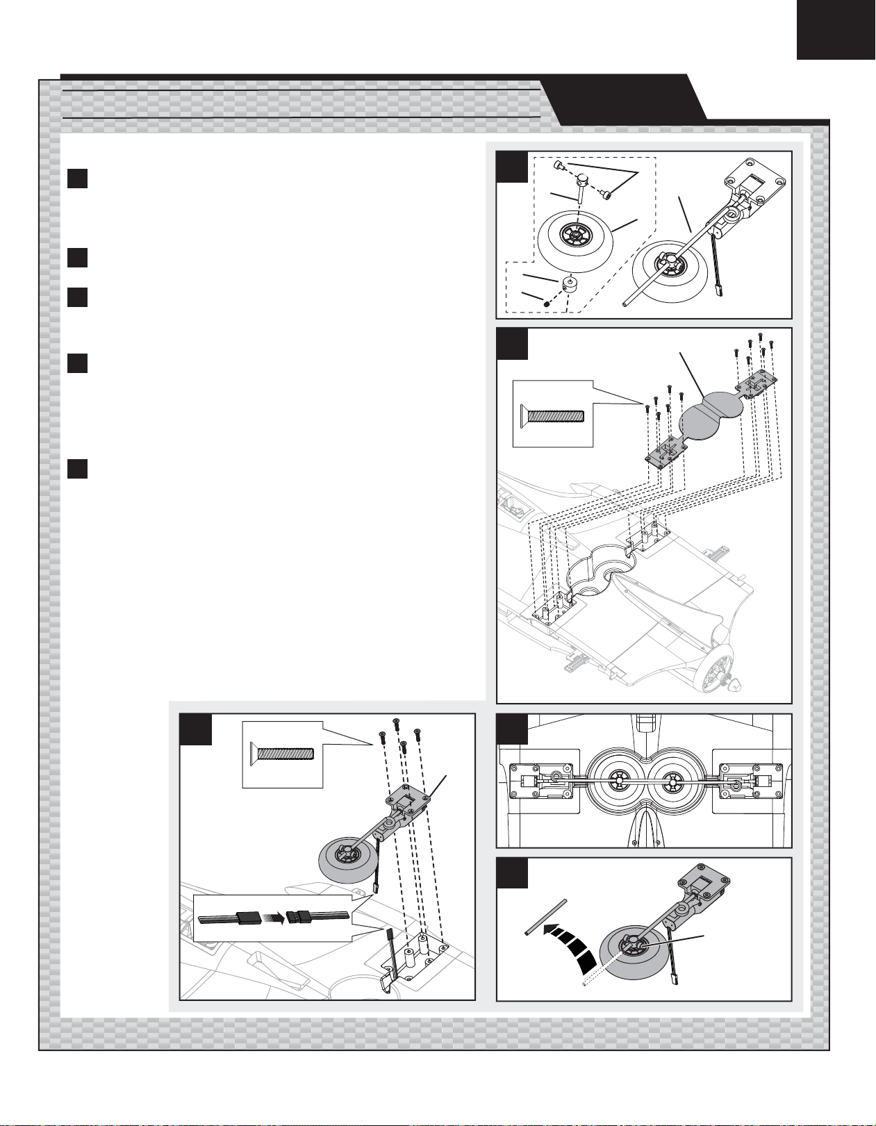
Installing Optional Retractable Landing Gear (Continued)
Installing Retractable Main Gear
1
• Install the Scimitar rear wheels (A) on the retract shafts (B) using the collars
(C) and setscrews (D).
• Loosely fi t the shafts (B) on the rear landing gear struts (E) using two
screws (F).
2
• Remove Main Gear Plate (G) from the fuselage by removing 12 screws (H).
1
C
3
• Put the retracts in the fuselage.
• Adjust the wheels and shafts on the struts so that the wheels almost touch in
the wheel wells.
D
2
4
• Mark the struts for cutting just below the shaft on the strut.
• Remove the wheels from the shafts.
• Carefully cut the struts to the marked length.
• Replace the wheels on the shafts.
• Tighten the two screws (F) of each shaft on each strut.
• Apply threadlock to the strut and wheel shaft hole.
5
• Connect the retracts to the gear extensions installed in the fuselage.
• Install each main retractable gear (J) on the left and right side of the fuselage
using four of the six screws (K) used for the fi xed gear.
• Connect the retract connnector to the GEAR port on your receiver.
• Operate the retracts. Make adjustments so that the wheels retract into the
wheel wells and extend without being blocked.
• Apply a small amount of threadlock to the wheel axle, collar and screw in
the collar.
OPTIONAL
B
2.5 X 10mm (12)
H
3 X 14mm (12)
F
E
A
G
5
K
3 X 14mm (4)
3
J
4
F
9
Page 10

EN
AILE
RUD
AILE
RUD
AILE
RUD
Installing Wings and Vertical Fins
AB
H
3 X 12mm (4)
1. Install the long carbon fi ber wing tube (A) into the rear hole on
the side of the fuselage.
2. Install the short carbon fi ber wing tube (B) into the front hole
on the side of the fuselage.
3. Install the left and right vertical fi n bodies (C) on the wing
tubes on each side of the fuselage using screws (D). (Rudder
control arms face the inner side of the vertical fi n.)
4. Connect the rudder servo connectors of the vertical fi ns to
connectors (E) (marked RUDD) on each side of the fuselage.
5. Install the left and right wings (F) on the wing tubes on each
side of fuselage.
6. Connect the aileron servo connectors to connectors (G)
(marked AILE) on each side of the fuselage.
NOTICE: Always put excess connector wire into the pocket of the
wing to prevent pinching of wires or other damage.
7. Turn over the model so the bottom of the fuselage faces up.
8. Make sure the left and right wings are fully in contact with
the fuselage, then install the four screws (H) in the wing and
fuselage.
E
C
G
D
2.5 X 14mm (2)
F
Disassemble the model in reverse order.
10
Page 11

Balancing the Propeller
NOTICE: Because of the Vector Thrust on the Scimitar, the propeller must be precisely balanced to prevent excess
vibration and damage to the vector thrust servo.
Your propeller needs to be balanced before you install it on your airplane. Balancing a propeller prevents motor
and/or airframe damage. Always balance a new propeller before use. The following procedure applies to propellers
of all brands and materials e.g., plastic, wood, carbon fi ber. The instructions below describe sanding or adding
material to a propeller to achieve proper balance. It is important to use a high-precision propeller balancer, like the
DU-BRO Tru Spin Propeller Balancer, in an area with no air movement.
Install the propeller on the balancer shaft. Make sure the propeller turns freely on the balancer shaft. Balance the
propeller using the instructions below.
TIP: If a propeller is diffi cult to balance, make sure the propeller’s hole is centered in the hub.
EN
BackFront
A
Horizontal Balancing
1. Align the propeller’s blade horizontally along the balancer shaft.
2. If the propeller blade falls out of horizontal alignment, carefully use sandpaper to remove a small amount of
plastic from the entire front of the heavier propeller blade (in the areas marked (A) on the illustrated propeller).
• Use 80-grit sandpaper to remove large amounts of material.
• Use a fi ner sandpaper (150-grit or greater) to remove small amounts of material for a
smoother fi nish.
Remove plastic from the blade until the propeller stays properly aligned in the horizontal position.
3. Use clear tape or paint to add material if you desire to avoid sanding your propeller.
• If tape is used, apply tape across the leading edge of the propeller to the back and front of the
propeller in order to prevent an increase in air resistance. Do not apply tape to the ears (B).
B
Vertical Balancing
1. Align the propeller’s blade vertically along the balancer shaft. (This is often called “balancing the hub”.)
2. If the propeller blade falls out of vertical alignment, modify the ears (B) on the center hub to achieve vertical
balance. Turn the prop to vertical and observe to which side of the hub the propeller falls. Remove material
from the heavier side of the hub (from the “ears” projecting from the side of the hub between the blades).
3. After vertical balancing, turn the propeller back to the horizontal position and make sure the propeller keeps its
horizontal balance. Keep turning the propeller between vertical and horizontal to make sure removing material
only improves balance.
Final Balancing
1. After vertical and horizontal balancing, turn the propeller to other angles along the balancer shaft.
2. If the propeller blades fall from an angle, carefully use sandpaper to remove a small amount of plastic from the
front of the heavier propeller blade or the ears on the hub until the propeller is fully balanced.
3. Remove plastic from the blade or ears until the propeller stays properly aligned along the balancer shaft at
any angle.
CAUTION: Always discard a chipped or cracked propeller. A damaged propeller can fail when turning at high speed, causing your airplane to crash. This
can cause property damage and/or injury.
For more information, view
John Redman’s propeller
balancing video at
www.horizonhobby.com.
VIDEO
NOTICE: If the propeller is not balanced, the vector thrust servo may be quickly damaged. Horizon Hobby does not warranty this if the servo is used under extreme
vibration or if the servo is used with an unbalanced propeller.
Installing the Propeller
1. Power off the ESC switch on the side of the fuselage or disconnect the
fl ight battery from the aircraft.
2. Remove the spinner nut (A) from the collet shaft (B).
3. Install a balanced propeller (C) on the collet shaft using the spinner nut
with the numbers on the propeller facing the front of the plane.
4. Put the shaft of a tool (for example, a screw driver) in the hole in the
side of the spinner to tighten the spinner on the collet shaft.
Remove the propeller in reverse order.
TIP: The propeller included with the Scimitar does not require the use of
the included washer. The washer must be installed between the backplate
and the propeller when an alternative balanced propeller has a hub
thinner than 13mm (from front to back).
CAUTION: After installation of the propeller, keep hands away from
the propeller. Always assume the motor is powered on and that the
propeller blades may turn at any time.
B
C
A
11
Page 12

EN
Opening the Fuselage
1
• Lift the front edge of the canopy (A) then pull the canopy
forward and off the fuselage.
• Loosen the screw (B) from the front of the receiver hatch (C), then
lift the front edge of the receiver hatch and pull it forward and off
the fuselage (carefully moving the tabs from under the retainers).
2
• Remove four screws (D) and the motor hatch (E) from the
fuselage.
Remove these hatches when setting up the Scimitar. Replace these
hatches before checking CG.
1
A
B
3 X 10mm
C
Installing the Vectored Thrust Lock
When the use of the Vectored Thrust (VT) is not desired, the VT can be locked.
Follow the directions below to lock the Vectored Thrust.
A B
2
2 X 14mm (2)
E
D
2.5 X 10mm (4)
C
D
The upper motor housing is not shown here for clarity. The upper motor housing may remain installed during setup.
1. Disconnect the vector-thrust servo connector from the AUX 1 servo
extension under the receiver hatch.
2. Remove the linkage (A) from the arms of the vector-thrust unit (B) and
the servo.
3. Install a screw (C) through both the arms of the vector-thrust unit and the
lock (D) into the fuselage.
4. Install the other end of the lock on the fuselage using a screw.
TIP: Four screws and the vector-thrust servo may be removed from the
fuselage if the vector-thrust lock is used. (See Servo Service instructions for
Vectored Thrust.)
12
Page 13

Control Centering
• Make sure servo directions (reversing) on your transmitter are
correct. Ensure control surfaces move freely by performing a
Control Test.
• Make sure trim and sub-trims are set to zero.
• Make sure the servo arms are set to 90 degrees. If not, remove
a servo arm and put the arm in a spline position closest to the
90 degree position (perpendicular to the servo’s long axis). If 90
degrees exactly cannot be reached, use the sub-trim on your
transmitter to adjust the servo arm to the 90 degree position.
• The Vectored-Thrust (VT) servo arm is neutral at the 11:30
position (on a clock face) (A) when looking down from above
while standing at the rear of the airplane. This neutral position
gives the VT servo maximum throw in both directions.
1
Elevons and Rudder Centering
• The center for the elevons is alignment with the trailing edge of the fuselage between the rudders.
• The center of the rudders is alignment with the center of the vertical fi n to which the rudder
is attached.
2
Vectored-Thrust Centering
CAUTION: Always disconnect the fl ight battery from the ESC before handling the propeller or
injury could result.
• Turn the propeller to horizontal on the model.
• From above the model, measure from the right end of the propeller (leading edge tip (B) to the center
of the back of the canopy (C).
• Measure from the left end of the propeller (leading edge tip (D)) to the center of the back of the
canopy (C).
• These two measurements (A to B and B to C) are the same distance when the VT unit is centered.
A
1
2
EN
C
Nose Gear Centering
• The center for nose steering occurs when the model follows a straight path while the rudder input is
at neutral.
TIP: When needed, turn the ball link or clevis until the control surface is at the center position
(up/down or left/right).
Refer to your transmitter’s manual for instructions about making adjustments to control surfaces,
Sub-Trim and Reverse.
Adjusting a Clevis or Ball link
After binding a transmitter to the model receiver, set trims and sub-trims to 0,
ensure servo arms are in the correct positions, then adjust clevises or ball links
to center the control surfaces.
Tip: Turn the clevis or ball link clockwise or counterclockwise on the linkage.
1
Adjusting a Clevis
• Pull the silicone tube from the clevis to the linkage.
• Carefully spread the clevis and put the clevis pin in a selected hole in the
control horn.
• Move the tube to tighten the clevis on the control horn.
2
Adjusting a Ball link
• Connect the ball link to the ball installed on the control horn using pliers or
ball link pliers.
• Install the linkage in a hole in the servo arm using a link cover.
AD
1
B
C
A
2
D
D
B
E
F
B
C
13
Page 14

EN
Factory Settings
Fly the model at factory settings before making changes. For pilots who wish
for more control throw, adjust the position of linkages on servo arms and
control horns for increased travel.
Transmitter Setup
CAUTION: For safe operation, always re-bind the airplane after setup is
complete to ensure the failsafe is updated with the latest setup.
A DSM2/DSMX six-channel (or better) computerized transmitter with adjustable dual rates, expo, delta/elevon mixing and programmable mixing for vector
thrust is recommended for fl ying the E-fl ite Scimitar. DX6i, DX7s, DX8, 9503,
11X or 12X transmitters may be used.
Flying wings are controlled by elevons (moveable surfaces on the wing).
Elevons take the aileron control (move opposite directions), and elevator control
(move up/down same direction) and mixes them together electronically through
the transmitter. Make sure both elevons move up and down (travel) the same
amount. This model tracks well when the left and right elevons travel the same
amount in response to the control stick.
Differential
This model requires differential. Differential is important for good axial roll. Set
the differential in your transmitter to reach the recommended throw for the
Scimitar elevons (described in control throws as Aileron/Elevator).
Arms
Transmitter Setup Checklist
Before binding:
1. Choose a blank model memory with only default (zero) settings (including trim and sub-trim).
2. Choose Wing Type as Delta Wing or Elevons.
3. Set servo reversing (as recommended on this page for your
transmitter).
After binding:
1. Check and adjust the servos so each arm’s neutral position
is perpendicular or as close to 90° as possible (loosen and
adjust the servo arm splines on the servo only when needed).
Use sub-trim to make fi ne adjustments.
2. Adjust linkage lengths so the control surfaces center when
the servo arm is perpendicular.
3. Set rates in the transmitter as recommended by measuring
the control surfaces and Vectored Thrust (VT).
4. Set the Differential (as recommended by measuring travel for
both ailerons).
RudderElevonsVectored Thrust (VT)Nose Gear
Vectored Thrust (VT) Mixing
Make sure the VT servo is connected to the Aux 1 port of the receiver. Set up a
programmable mix of Rudder to Aux 1 (channel 6). Use linear mixing and adjust
the mix to reach maximum travel of the VT unit. (See next page for adjustment
of maximum throws.) Select a switch to power on and off this mix. Use this
switch to help you get familiar with the VT.
Make sure the vectored thrust (VT) is at neutral when mixing is on or off. Make
sure both rudders are perfectly neutral.
Aileron Trim or Throttle to Aileron Mixing
Due to the high torque required to support the Scimitar fl ight envelope, the
torque effect tends to make the model roll left as power is increased. It is
recommended before takeoff to adjust the aileron trim to compensate for this
torque. After the Scimitar’s ailerons are centered, add between 1 and 1.5mm
of right aileron trim to your transmitter. On the Spektrum DX8, this translates
to approximately 8 clicks of right aileron trim when using the default trim rate.
Download Quique’s DX8 program, which includes throttle to aileron mix in
order to compensate for the torque (letting you keep aileron trim at the neutral
position).
ONLINE
For more information, Videos and advanced settings including Quique
explaining how to fl y the Scimitar, operate VT and doing aerobatic
maneuvers, visit www.E-fl iteRC.com/Carbon-Z.
Also available for download is Quique’s DX8 program.
CAUTION: Make sure the rudder and VT travel in the same direction.
If the VT unit and rudder travel in opposite directions, the propeller will
touch the rudders and damage them, causing the airplane to crash.
We recommend this setup for servo channel reversing for the DX7,
DX7S and DX8 transmitters ( Same for JR9303/9503, 11X and 12X ):
Throttle: Normal Aileron: Reverse
Elevator: Reverse Rudder: Normal
For the DX6i, we recommend this setup for servo channel reversing:
Throttle: Normal Aileron: Reverse
Elevator: Normal Rudder: Normal
NOTICE: When setting up the model for control using a Spectrum DX6i
transmitter, swap servo connections between the aileron and elevator
ports on the receiver (from factory settings). Do a control test to make
sure the model operates correctly.
14
Page 15

Model Setup-Control Throws
Rudders
Measure from the center line (A) of the sub-fi n to the rear lower tip of a rudder
(B) to calculate the distance from the center of travel for the rudders.
Vectored-Thrust (VT) Unit
Remove the motor hatch and look at the VT unit when adjusting mixes or travel
for the AUX1 channel in your transmitter. Start with 100% Aux 1 servo travel,
but a low % value in your programmable mixing (for example, 80%). With the
mix on and the rudder set to high rate, move the rudder stick to one of the
extreme positions. While holding the rudder at that position, increase the mix
% until you see the VT unit reach its limit. Move the rudder stick to the other
extreme and increase the mix % until you see the VT unit reach its limit. This
sets maximum throw in both directions. Adjust servo travel so that you do not
make the servo turn more than the VT unit can move in the fuselage.
CAUTION: Never exceed the maximum servo travel values listed in the
manual. Doing so could cause servo failure or battery drain and a crash,
resulting in damage to property and injury.
EN
A
B
A
VIDEO
For more information, Visit www.E-fl iteRC.com/Carbon-Z to see
Quique explain the basics on how to maneuver with the vectored thrust.
Elevons
Before making measurements, mark a horizontal line from the center of the
screw (C) in the vertical fi n to the bevel between the vertical fi n and the rudder.
1
Up Elevon:
Measure from the line (C) marked at the bevel between the vertical fi n and the
rudder to an imaginary line (D) even with the inside corner at the top of the
elevon.
2
Down Elevon:
Measure from the line (C) marked at the bevel between the vertical fi n and the
rudder to an imaginary line (E) even with the inside corner on the bottom of the
elevon.
The elevons function as elevators; both sides must travel equally up and down.
If they do not, the plane will not track straight in loops or corners.
B
High Rate Low Rate Expo
Rudder 80mm left/right 50mm left/right High-30%, Low-10%
1
D
C
2
C
E
High Rate Low Rate Expo
Aileron right/left One aileron down
21mm the
opposite aileron
up 38mm while
stick is held to
full right or left
position.
Elevator up/down 44mm/36mm 25mm/17mm High-55%, Low-20%
One aileron down
17mm the
opposite aileron
up 34mm while
stick is held to
full right or left
position.
High-45%, Low-35%
15
Page 16

EN
Center of Gravity (CG)
CG is generally located at 553mm to 565mm from the front end
of the aircraft. Flying wings like the Scimitar are more sensitive
to changes in CG. Not using the recommended CG position may
result in a variable or overall poor performance in some areas of
the fl ight envelope.
To start, place the recommended 3200mAh battery all the way
forward in the fuselage. Hold the battery in place using the front
and middle hook and loop straps. Adjust the battery’s position as
needed to stay in the recommended measurement range for CG.
553–565mm
From the front end
of the aircraft.
Control Direction Test
Bind your aircraft and transmitter before doing these tests. Move the controls on the transmitter to make sure the aircraft control surfaces move correctly. After
doing the Control Test, correctly set failsafes. Make sure transmitter controls are at neutral and the throttle and throttle trim are in the low position, then rebind the
model to your transmitter. If the receiver loses its link to the transmitter, the failsafe makes the controls and throttle revert to the settings made at binding.
Elevator
Aileron
Rudder
Vectored Thrust
Down Elevator Command UP Elevator Command
Stick Right Stick Left
Stick Right Stick Left
Stick Right Stick Left
Looking from top down Looking from top down
16
Page 17

Prefl ight Checklist
EN
1. Charge fl ight battery.
2. Install fl ight battery in the aircraft (once it has been fully
charged).
3. Make sure linkages move freely.
4. Perform Control Direction Test with the transmitter.
Flying Tips
Range Check your Radio System
After fi nal assembly, range check the radio system with the E-fl ite Scimitar.
Refer to your specifi c transmitter instruction manual for range test information.
Launching
CAUTION: The Scimitar is designed for use with landing gear. Do not
hand launch this model or attempt to fl y without installing landing gear.
Damage or injury could result.
Always inspect and repair your model before fl ying. Any damage or loose linkages can decrease control in high-speed fl ight. Always take off into the wind,
but also be aware of cross winds on the runway. Take off in low rate without
use of mix that enables Vectored Thrust (VT).
Flying
The Scimitar is intended for intermediate pilots when VT is not used or the VT
lock is installed. VT on the Scimitar is intended for use only by intermediate-toadvanced pilots.
The Scimitar is a powerful aircraft with a wide range of air speeds and a wide
aerobatic envelope. This model is equipped with VT and, because of this feature, you must handle the airplane with respect until you develop experience
with maneuvering with VT.
At fi rst fl ight, fl y the model in low rate. The fi rst time you use high rate,
fl y at low to medium speed. Begin using VT only at a high altitude so there is
room to maneuver.
Tip: Before takeoff set elevator trim up 2–3mm to provide the proper refl ex for
best trim pitch.
VT increases yaw. Using the twin rudders, VT can put the airplane into a fl at
spin, pin wheel or other aerobatic maneuvers at a surprisingly high rotational
speed. Perform these maneuvers only at altitudes that will give you room to
recover full control.
The VT works based on thrust (motor rpm); the higher the rpm, the higher the
thrust. The greater the angle the VT unit defl ects, the greater the yaw authority
will be, as well as the rotational speed. Remember that recovering the airplane
from a fl at spin to forward fl ight requires the VT to be turned in the opposite
direction of the spin, without decreasing power to the motor. Once you see the
rotation stop, reduce power to get the nose down and fl y out.
5. Adjust fl ight controls and transmitter.
6. Perform a radio system Range Check.
7. Find a safe and open area.
8. Plan fl ight for fl ying fi eld conditions.
NOTICE: Horizon Hobby does not warranty the airplane for crash damage, with
or without use of the VT feature.
Always choose a wide-open space for fl ying your E-fl ite Scimitar. It is ideal for
you to fl y at a sanctioned fl ying fi eld. If you are not fl ying at an approved site,
always avoid fl ying near houses, trees, wires and buildings. You should also
be careful to avoid fl ying in areas where there are many people, such as busy
parks, schoolyards, or soccer fi elds. Consult local laws and ordinances before
choosing a location to fl y your aircraft.
Landing
For your fi rst fl ights, set your transmitter timer to 4 1/2 minutes. Adjust your
timer for longer or shorter fl ights once you have fl own the model. At high rate,
fl y the airplane down to the ground using 1/4 –1/3 throttle to keep enough energy for a proper fl are. Before the model touches down, always fully decrease
throttle to avoid damage to propeller, motor, ESC or other components.
Repairs
Thanks to the Carbon-Z™ construction of the Scimitar, repairs to the
Z-Foam™ can be made using virtually any adhesive (hot glue, regular CA,
epoxy, etc). When parts are not repairable, see the Replacement Parts List for
ordering by item number.
NOTICE: Use of CA accelerant on your model can damage paint. DO NOT
handle model until accelerant fully dries.
NOTICE: When fi nished fl ying, never keep the airplane in the sun. Do not store
the aircraft in a hot, enclosed area such as a car. Doing so can damage
the foam.
Post Flight Checklist
After Flying Check List
1. Disconnect fl ight battery from ESC (Required for Safety and
battery life).
2. Power off transmitter.
3. Remove fl ight battery from aircraft.
4. Recharge fl ight battery.
After Flying Check List
5. Store fl ight battery apart from aircraft and monitor the battery
charge.
6. Make note of fl ight conditions and fl ight plan results,
planning for future fl ights.
17
Page 18

EN
Fuselage Nose Service
1. Remove the canopy and battery from the fuselage.
2. Remove four screws (A), two in the plate in the bottom of the battery
compartment and two on the left and right sides inside the fuselage.
3. A small amount of glue holds the nose on the fuselage, take care in
removing it from the fuselage.
4. Replace nose using the four screws and a small amount of CA.
Control Surface Service
MAINTENANCE
A
2.5 X 10mm (4)
MAINTENANCE
1. Before disassembling a control surface, remove the wing or
vertical fi n from the fuselage.
2. Disconnect the linkage from the control horn.
3. Remove a screw (A) from each end of the control surface
hinge (B).
4. Carefully pull the control surface hinge pin and control
surface from the main body of the control surface.
5. Install the control surface by carefully aligning and pushing
the hinge pin in the clamps in the main body of the wing or
vertical fi n.
6. Apply a small amount of threadlock to the screws and install
in each end of the hinge pin.
CAUTION: Tighten the screw on each end of the hinge
until it is fl ush with the outer face of the hinge surface. Tightening the screw too much prevents the control from moving freely
on the hinge, which can result in a crash, damage or injury.
7. Connect the servo linkage to the control horn.
8. Install the wing or vertical fi n to the fuselage and center the
control surface.
CAUTION: After replacing a control surface, always
ensure the control surface is centered. If you adjust a control
surface’s center, always do a control test and rebind the model
to your transmitter to correctly set the failsafe.
Wing
B
A
2 X 6mm (2)
Vertical Fin
B
18
A
2 X 6mm (2)
Page 19

EN
Servo Service
Nose Gear
1. Remove the three screws (A) from the steering servo.
2. Remove the steering linkage from the servo arm.
3. Remove the servo from the fuselage
4. Disconnect the servo connector from the servo extension
in the fuselage.
Assemble in reverse order.
Wing
1. Remove the wing from the model.
2. Remove the two screws (B) and aileron servo cover from
the wing.
3. Remove the linkage (C) from the servo arm.
4. Remove the servo from the wing (the servo connector
goes through a channel in the wing to the fuselage).
Assemble in reverse order.
MAINTENANCE
A
2.5 X 8mm (3)
C
B
2.5 X 8mm (2)
Vertical Fins
1. Remove the wing and vertical fi n from the model.
2. Remove the two screws (D) and retainer plate from the
vertical fi n.
3. Remove the linkage from the servo arm.
4. Remove the servo from the vertical fi n.
Assemble in reverse order.
Vectored Thrust
1. Open the fuselage to gain access to the vectored
thrust servo.
2. Remove the four screws (E) from the servo.
3. Remove the linkage from the servo arm.
4. Disconnect the servo connector from the AUX1 servo
extension in the fuselage.
Assemble in reverse order.
D
2.5 X 8mm (2)
E
2.5 X 8mm (4)
19
Page 20

EN
Sub-Fin Service
1. Turn over the model so the bottom faces up.
2. Remove the six screws and sub-fi n from the fuselage.
Assemble in reverse order.
Motor and Vectored-Thrust Service
MAINTENANCE
2.5 X 10mm (6)
MAINTENANCE
Disassembly
1. Open the fuselage.
2. Remove the 12 screws (A) and upper motor housing (B) from the model.
2. Disconnect the motor wires from the ESC.
3. Disconnect the ball link from the arm of the vector-thrust servo or disconnect the vector-thrust unit’s arm from the lock to the fuselage, by removing the screw.
4. Remove the upper housing from the fuselage. The upper and lower bearings may block easy removal of the housing and the vector-thrust unit
from the fuselage.
5. Remove the vector-thrust unit (A) from the fuselage.
6. Remove the four screws (B), washers (C) and X-mount (D) from the
vector-thrust unit.
7. Remove four screws (E) and washers (F) from the X-mount
and motor (G).
A D
Assembly
Assemble in reverse order, aligning wire colors of the motor with the ESC for
correct operation. Remember to use threadlock.
NOTICE: Make sure the propeller side with the numbers for diameter and
pitch (for example, 10 x 8) faces forward towards the front of the plane. A tool
is required to tighten the spinner nut on the collet.
A
B
2.5 X 10mm (12)
C
(4)
BG
3 X 12mm (4)
20
Not all wiring shown.
(4)
F
E
4 X 9mm (4)
Page 21

Troubleshooting Guide
Problem Possible Cause Solution
Aircraft will not respond
to throttle but responds to
other controls
Extra propeller noise or
extra vibration
Reduced fl ight time or aircraft underpowered
Aircraft will not Bind (during binding) to transmitter
Aircraft will not link (after
binding) to transmitter
Control surface does not
move
Controls reversed Transmitter settings are reversed Do the Control Direction Test and adjust controls on
Motor power pulses then
motor loses power
Throttle is not at idle and/or throttle trim is too high Reset controls with throttle stick and throttle trim
at lowest setting
Throttle servo travel is lower than 100% Make sure throttle servo travel is 100% or greater
Throttle channel is reversed Reverse throttle channel on transmitter
Damaged propeller and spinner, collet or motor Replace damaged parts
Propeller is out of balance Balance or replace propeller
Flight battery charge is low Completely recharge fl ight battery
Propeller is installed backwards Install propeller with numbers facing forward towards the
front of the aircraft
Flight battery is damaged Replace fl ight battery and follow fl ight battery instructions
Flight conditions may be too cold Make sure battery is warm before use
Battery capacity may be too low for fl ight conditions Replace battery or use a larger capacity battery
Transmitter is too near aircraft during binding process Move powered transmitter a few feet from aircraft,
disconnect and reconnect fl ight battery to aircraft
Aircraft or transmitter is too close to large metal object Move aircraft or transmitter away from large metal object
Bind plug is not installed correctly in bind port extension Install bind plug in bind port extension and bind
aircraft to transmitter
Flight battery/Transmitter battery charge is too low Replace/recharge batteries
ESC switch is off Power on ESC switch
Transmitter is too near aircraft during linking process Move powered transmitter a few feet from aircraft,
disconnect and reconnect fl ight battery to aircraft
Aircraft or transmitter is too close to large metal object Move aircraft or transmitter away from large metal object
Bind plug is left installed in bind port extension Rebind transmitter to aircraft and remove bind plug before
cycling power
Aircraft bound to different model memory (ModelMatch™ radios
only)
Flight battery/Transmitter battery charge is too low Replace/recharge batteries
Transmitter may have been bound to a different model (using
different DSM Protocol)
ESC switch is off Power on ESC switch
Control surface, control horn, linkage or servo damage Replace or repair damaged parts and adjust controls
Wire is damaged or connections are loose Do a check of wires and connections, connect
Transmitter is not bound correctly or the incorrect model
was selected
BEC (Battery Elimination Circuit) of the ESC is damaged Replace ESC
ESC switch is off Power on ESC switch
ESC uses default soft Low Voltage Cutoff (LVC) Recharge fl ight battery or replace battery
Weather conditions might be too cold Postpone flight until weather is warmer
Battery is old, worn out or damaged Replace battery
Battery C rating might be too small Use recommended 25C battery
Select correct model memory on transmitter
Bind aircraft to transmitter
or replace as needed
Re-bind or select correct model in transmitter
transmitter appropriately
that is no longer performing
EN
21
Page 22

EN
AMA National Model Aircraft Safety Code
Effective January 1, 2011
A. GENERAL
A model aircraft is a non-human-carrying aircraft capable of sustained fl ight
in the atmosphere. It may not exceed limitations of this code and is intended
exclusively for sport, recreation and/or competition. All model fl ights must be
conducted in accordance with this safety code and any additional rules specifi c
to the fl ying site.
1. Model aircraft will not be fl own:
(a) In a careless or reckless manner.
(b) At a location where model aircraft activities are prohibited.
2. Model aircraft pilots will:
(a) Yield the right of way to all man carrying aircraft.
(b) See and avoid all aircraft and a spotter must be used when appropriate.
(AMA Document #540-D-See and Avoid Guidance.)
(c) Not fl y higher than approximately 400 feet above ground level within
three (3) miles of an airport, without notifying the airport operator.
(d) Not interfere with operations and traffi c patterns at any airport, heliport
or seaplane base except where there is a mixed use agreement.
(e) Not exceed a takeoff weight, including fuel, of 55 pounds unless in
compliance with the AMA Large Model Aircraft program. (AMA
Document 520-A)
(f) Ensure the aircraft is identifi ed with the name and address or AMA
number of the owner on the inside or affi xed to the outside of the
model
aircraft. (This does not apply to model aircraft fl own indoors).
(g) Not operate aircraft with metal-blade propellers or with gaseous boosts
except for helicopters operated under the provisions of AMA Document
#555.
(h) Not operate model aircraft while under the infl uence of alcohol or while
using any drug which could adversely affect the pilot’s ability to safely
control the model.
(i) Not operate model aircraft carrying pyrotechnic devices which explode
or burn, or any device which propels a projectile or drops any object
that creates a hazard to persons or property.
Exceptions:
• Free Flight fuses or devices that burn producing smoke and are
securely attached to the model aircraft during fl ight.
• Rocket motors (using solid propellant) up to a G-series size may
be used provided they remain attached to the model during fl ight.
Model rockets may be fl own in accordance with the National
Model Rocketry Safety Code but may not be launched from
model aircraft.
• Offi cially designated AMA Air Show Teams (AST) are authorized to
use devices and practices as defi ned within the Team AMA
Program Document (AMA Document #718).
(j) Not operate a turbine-powered aircraft, unless in compliance with the
AMA turbine regulations. (AMA Document #510-A).
3. Model aircraft will not be fl own in AMA sanctioned events, air shows or
model demonstrations unless:
(a) The aircraft, control system and pilot skills have successfully
demonstrated all maneuvers intended or anticipated prior to the
specifi c event.
(b) An inexperienced pilot is assisted by an experienced pilot.
4. When and where required by rule, helmets must be properly worn and
fastened. They must be OSHA, DOT, ANSI, SNELL or NOCSAE approved or
comply with comparable standards.
B. RADIO CONTROL
1. All pilots shall avoid fl ying directly over unprotected people, vessels,
vehicles or structures and shall avoid endangerment of life and property
of others.
2. A successful radio equipment ground-range check in accordance with
manufacturer’s recommendations will be completed before the fi rst fl ight
of a new or repaired model aircraft.
3. At all fl ying sites a safety line(s) must be established in front of which all
fl ying takes place (AMA Document #706-Recommended Field Layout):
(a) Only personnel associated with fl ying the model aircraft are allowed at
or in front of the safety line.
(b) At air shows or demonstrations, a straight safety line must be
established.
(c) An area away from the safety line must be maintained for spectators.
(d) Intentional fl ying behind the safety line is prohibited.
4. RC model aircraft must use the radio-control frequencies currently allowed
by the Federal Communications Commission (FCC). Only individuals
properly licensed by the FCC are authorized to operate equipment on
Amateur Band frequencies.
5. RC model aircraft will not operate within three (3) miles of any pre-existing
fl ying site without a frequency-management agreement (AMA Documents
#922-Testing for RF Interference; #923- Frequency Management
Agreement)
6. With the exception of events fl own under offi cial AMA Competition
Regulations, excluding takeoff and landing, no powered model may be
fl own outdoors closer than 25 feet to any individual, except for the pilot
and the pilot’s helper(s) located at the fl ight line.
7. Under no circumstances may a pilot or other person touch a model aircraft
in fl ight while it is still under power, except to divert it from striking an
individual. This does not apply to model aircraft fl own indoors.
8. RC night fl ying requires a lighting system providing the pilot with a clear
view of the model’s attitude and orientation at all times.
9. The pilot of a RC model aircraft shall:
(a) Maintain control during the entire fl ight, maintaining visual contact
without enhancement other than by corrective lenses prescribed for
the pilot.
(b) Fly using the assistance of a camera or First-Person View (FPV) only
in accordance with the procedures outlined in AMA Document #550.
Please see your local or regional modeling association’s guidelines for proper, safe
operation of your model aircraft.
22
Page 23

Limited Warranty
EN
What this Warranty Covers
Horizon Hobby, Inc. (“Horizon”) warrants to the original purchaser that the
product purchased (the “Product”) will be free from defects in materials and
workmanship at the date of purchase.
What is Not Covered
This warranty is not transferable and does not cover (i) cosmetic damage, (ii)
damage due to acts of God, accident, misuse, abuse, negligence, commercial
use, or due to improper use, installation, operation or maintenance, (iii) modifi cation of or to any part of the Product, (iv) attempted service by anyone other
than a Horizon Hobby authorized service center, or (v) Products not purchased
from an authorized Horizon dealer.
OTHER THAN THE EXPRESS WARRANTY ABOVE, HORIZON MAKES NO OTHER
WARRANTY OR REPRESENTATION, AND HEREBY DISCLAIMS ANY AND ALL
IMPLIED WARRANTIES, INCLUDING, WITHOUT LIMITATION, THE IMPLIED WARRANTIES OF NON-INFRINGEMENT, MERCHANTABILITY AND FITNESS FOR A
PARTICULAR PURPOSE. THE PURCHASER ACKNOWLEDGES THAT THEY ALONE
HAVE DETERMINED THAT THE PRODUCT WILL SUITABLY MEET THE REQUIREMENTS OF THE PURCHASER’S INTENDED USE.
Purchaser’s Remedy
Horizon’s sole obligation and purchaser’s sole and exclusive remedy shall be
that Horizon will, at its option, either (i) service, or (ii) replace, any Product
determined by Horizon to be defective. Horizon reserves the right to inspect
any and all Product(s) involved in a warranty claim. Service or replacement
decisions are at the sole discretion of Horizon. Proof of purchase is required for
all warranty claims. SERVICE OR REPLACEMENT AS PROVIDED UNDER THIS
WARRANTY IS THE PURCHASER’S SOLE AND EXCLUSIVE REMEDY.
Inspection or Services
If this Product needs to be inspected or serviced, please use the Horizon Online
Service Request submission process found on our website or call Horizon to
obtain a Return Merchandise Authorization (RMA) number. Pack the Product
securely using a shipping carton. Please note that original boxes may be
included, but are not designed to withstand the rigors of shipping without additional protection. Ship via a carrier that provides tracking and insurance for
lost or damaged parcels, as Horizon is not responsible for merchandise until it
arrives and is accepted at our facility. An Online Service Request is available
at www.horizonhobby.com under the Support tab. If you do not have internet
access, please contact Horizon Product Support to obtain a RMA number
along with instructions for submitting your product for service. When calling
Horizon, you will be asked to provide your complete name, street address,
email address and phone number where you can be reached during business
hours. When sending product into Horizon, please include your RMA number, a
list of the included items, and a brief summary of the problem. A copy of your
original sales receipt must be included for warranty consideration. Be sure
your name, address, and RMA number are clearly written on the outside of the
shipping carton.
Notice: Do not ship LiPo batteries to Horizon. If you have any issue with a
LiPo battery, please contact the appropriate Horizon Product
Support offi ce.
Warranty Requirements
For Warranty consideration, you must include your original sales receipt
verifying the proof-of-purchase date. Provided warranty conditions have
been met, your Product will be serviced or replaced free of charge. Service or
replacement decisions are at the sole discretion of Horizon.
Limitation of Liability
HORIZON SHALL NOT BE LIABLE FOR SPECIAL, INDIRECT, INCIDENTAL OR
CONSEQUENTIAL DAMAGES, LOSS OF PROFITS OR PRODUCTION OR COMMERCIAL LOSS IN ANY WAY, REGARDLESS OF WHETHER SUCH CLAIM IS BASED IN
CONTRACT, WARRANTY, TORT, NEGLIGENCE, STRICT LIABILITY OR ANY OTHER
THEORY OF LIABILITY, EVEN IF HORIZON HAS BEEN ADVISED OF THE POSSIBILITY OF SUCH DAMAGES. Further, in no event shall the liability of Horizon exceed
the individual price of the Product on which liability is asserted. As Horizon has
no control over use, setup, fi nal assembly, modifi cation or misuse, no liability
shall be assumed nor accepted for any resulting damage or injury. By the act
of use, setup or assembly, the user accepts all resulting liability. If you as the
purchaser or user are not prepared to accept the liability associated with the
use of the Product, purchaser is advised to return the Product immediately in
new and unused condition to the place of purchase.
Law
These terms are governed by Illinois law (without regard to confl ict of law
principals). This warranty gives you specifi c legal rights, and you may also
have other rights which vary from state to state. Horizon reserves the right to
change or modify this warranty at any time without notice.
Warranty Services
Questions, Assistance, and Services
Your local hobby store and/or place of purchase cannot provide warranty support or service. Once assembly, setup or use of the Product has been started,
you must contact your local distributor or Horizon directly. This will enable Horizon to better answer your questions and service you in the event that you may
need any assistance. For questions or assistance, please direct your email to
productsupport@horizonhobby.com, or call 877.504.0233 toll free to speak to
a Product Support representative. You may also find information on our website
at www.horizonhobby.com
Non-Warranty Service
Should your service not be covered by warranty service will be completed and payment will be required without notifi cation or estimate of
the expense unless the expense exceeds 50% of the retail purchase cost.
By submitting the item for service you are agreeing to payment of the service
without notifi cation. Service estimates are available upon request. You must
include this request with your item submitted for service. Non-warranty service
estimates will be billed a minimum of ½ hour of labor. In addition you will be
billed for return freight. Horizon accepts money orders and cashiers checks, as
well as Visa, MasterCard, American Express, and Discover cards. By submitting
any item to Horizon for service, you are agreeing to Horizon’s Terms and Conditions found on our website www.horizonhobby.com/Service/Request/.
23
Page 24

EN
Contact Information
Country of Purchase Horizon Hobby Address Phone Number/Email Address
United States of
America
United Kingdom Horizon Hobby Limited
Germany Horizon Technischer Service
France Horizon Hobby SAS
Horizon Service Center
(Electronics and engines)
Horizon Product Support
(All other products)
4105 Fieldstone Rd
Champaign, Illinois
61822 USA
4105 Fieldstone Rd
Champaign, Illinois
61822 USA
Units 1-4 Ployters Rd
Staple Tye
Harlow, Essex
CM18 7NS
United Kingdom
Hamburger Str. 10
25335 Elmshorn
Germany
14 Rue Gustave Eiffel
Zone d’Activité du Réveil Matin
91230 Montgeron
877-504-0233
Online Repair Request:
visit www.horizonhobby.com/service
877-504-0233
productsupport@horizonhobby.com
+44 (0) 1279 641 097
sales@horizonhobby.co.uk
+49 4121 46199 66
service@horizonhobby.de
+33 (0) 1 60 47 44 70
infofrance@horizonhobby.com
Compliance Information for the European Union
Declaration of Conformity
(in accordance with ISO/IEC 17050-1)
No. HH2011093002
Product(s): Carbon-Z Scimitar BNF
Item Number(s): EFL10180
Equipment class: 1
The object of declaration described above is in conformity with the requirements of the specifi cations listed below, following the provisions of the
European R&TTE directive 1999/5/EC and EMC Directive 2004/108/EC:
EN 301 489-1 V1.7.1: 2006
EN 301 489-17 V1.3.2: 2008
EN55022: 2010
EN55024: 2010
Signed for and on behalf of:
Horizon Hobby, Inc.
Champaign, IL USA
Sep. 30, 2011
International Operations and
Steven A. Hall
Vice President
Risk Management
Horizon Hobby, Inc.
Declaration of Conformity
(in accordance with ISO/IEC 17050-1)
No. HH2011093001
Product(s): Carbon-Z Scimitar PNP
Item Number(s): EFL10175
Equipment class: 1
The object of declaration described above is in conformity with the requirements of the specifi cations listed below, following the provisions of the EMC
Directive 2004/108/EC
EN55022: 2010
EN55024: 2010
Signed for and on behalf of:
Horizon Hobby, Inc.
Champaign, IL USA
Sep. 30, 2011
International Operations and
Steven A. Hall
Vice President
Risk Management
Horizon Hobby, Inc.
Instructions for disposal of WEEE by users in the European Union
This product must not be disposed of with other waste. Instead, it is the user’s responsibility to dispose of their waste equipment by handing it over
to a designated collections point for the recycling of waste electrical and electronic equipment. The separate collection and recycling of your waste
equipment at the time of disposal will help to conserve natural resources and ensure that it is recycled in a manner that protects human health and
the environment. For more information about where you can drop off your waste equipment for recycling, please contact your local city offi ce, your
household waste disposal service or where you purchased the product.
24
Page 25

Parts Contact Information • Kontaktinformationen für Ersatzteile
• Coordonnés pour obtenir de piéces détachées • Recapiti per i ricambi
Country of Purchase Horizon Hobby Address Phone Number/Email Address
United States of
America
United Kingdom Horizon Hobby Limited
Germany Horizon Hobby GmbH
France Horizon Hobby SAS
Sales
4105 Fieldstone Rd
Champaign, Illinois 61822 USA
Units 1-4 Ployters Rd
Staple Tye
Harlow, Essex
CM18 7NS United Kingdom
Hamburger Str. 10
25335 Elmshorn
Germany
14 Rue Gustave Eiffel
Zone d’Activité du Réveil Matin
91230 Montgeron
800-338-4639
Sales@horizonhobby.com
+44 (0) 1279 641 097
sales@horizonhobby.co.uk
+49 4121 46199 60
service@horizonhobby.de
+33 (0) 1 60 47 44 70
infofrance@horizonhobby.com
9191
Page 26

IT
Replacement Parts • Ersatzteile • Piéces de rechange • Pezzi di ricambio
Part # | Nummer
Numéro | Codice
EFL1018017
EFLP1008E
EFLR7145
EFLR71451
EFLR71452
EFLR71453
EFLR714554
EFL1018030
EFL1018031
EFLM7402
EFLM7400
EFLM7401
EFL1018024
EFL1018021
EFL1018022
EFL1018023
EFL1018001
EFL1018002
EFL1018012
EFL1018026
EFL1018027
EFL1018008
EFL1018025
EFL1018006
EFL1018011
EFL1018029
EFL1018015
EFL1018005
EFL1018007
EFL1018009
EFL1018014
EFL1018010
EFL1008018
EFL1018016
Description Beschreibung Description Descrizione
Nose Strut Retract: C-Z Scimitar Einziehbares Bugstrebenfahrwerk:
10 X 8 Electric Propeller:
C-Z Scimitar
26 g Digital MG Mini Servo Digitaler MG-Miniservo 26g Servo miniature MG numérique 26g Mini servo MG digitale 26 g
Gear Set: 26 g Digital MG Mini
Servo
Case Set: 26 g Digital MG Mini
Servo
Aluminum Servo Arm: 26 g Digital
MG Mini Servo
Plastic Servo Arm: 26 g MG Mini
Servo
Nose Protector: C-Z Scimitar Nasenschutz: C-Z Scimitar Protecteur de nez: C-Z Scimitar Protezione punta: C-Z Scimitar
Complete Screw Set: C-Z Scimitar Kompletter Schraubensatz:
Prop Adapter with Cone:
C-Z Scimitar
BL32 Brushless Outrunner
Motor, 1010 Kv
Motor Shaft: BL32 Outrunner Motorwelle: BL32-Außenläufer Arbre de moteur: cage-tournante BL32 Albero motore: outrunner BL32
Motor Mount with Screws:
C-Z Scimitar
Vector-Thrust Servo Arm & Pushrod:
C-Z Scimitar
Decal Sheet: C-Z Scimitar Dekorbogen: C-Z Scimitar Planche de décalcomanies:
Servo Extension Set: C-Z Scmitar Servoerweiterungssatz: C-Z Scimitar Jeu de rallonges servo: C-Z Scimitar Set estensione servo: C-Z Scimitar
Wing Panel, Right: C-Z Scimitar Flügelfl äche, rechts: C-Z Scimitar Panneau d’aile, droite: C-Z Scimitar Pannello ala, destro: C-Z Scimitar
Wing Panel, Left: C-Z Scimitar Flügelfl äche, links: C-Z Scimitar Panneau d’aile, gauche: C-Z Scimitar Pannello ala, sinistro: C-Z Scimitar
Wing Tube Front & Rear:
C-Z Scimitar
Vector-Thrust Complete Unit:
C-ZScimitar
Motor Hatch: C-Z Scimitar Motorabdeckung: C-Z Scimitar Capot du moteur: C-Z Scimitar Portello motore: C-Z Scimitar
Radio Hatch: C-Z Scimitar Funkabdeckung: C-Z Scimitar Capot de la radio: C-Z Scimitar Portello radio: C-Z Scimitar
Wing & Rudder Screw Set:
C-Z Scimitar
Vertical Fin Left: C-Z Scimitar Seitenleitwerk links: C-Z Scimitar Dérive verticale gauche: C-Z Scimitar Deriva verticale sinistra:
Complete Pushrod Set:
C-Z Scimitar
Vector-Thrust Locker: C-Z Scimitar Vektorschubsperre: C-Z Scimitar Verrou de poussée vectorielle:
Vertical Fin Bottom: C-Z Scimitar Seitenleitwerk unten: C-Z Scimitar Dérive verticale basse: C-Z Scimitar Parte inferiore della deriva verticale:
Fuselage with Hatches:
C-Z Scimitar
Vertical Fin Right: C-Z Scimitar Seitenleitwerk rechts: C-Z Scimitar Dérive verticale droite: C-Z Scimitar Deriva verticale destra: C-Z Scimitar
Complete Canopy & Pilot:
C-Z Scimitar
Nose Gear & Mount: C-Z Scimitar Bugfahrwerk und Halterung:
Nose & Screws: C-Z Scimitar Nase und Schrauben: C-Z Scimitar Nez et vis: C-Z Scimitar Punta e viti: C-Z Scimitar
Wheel Set: C-Z Scimitar Radsatz: C-Z Scimitar Jeu de roues: C-Z Scimitar Set ruota: C-Z Scimitar
Main Landing Gear & Mount:
C-ZScimitar
C-ZScimitar
10 X 8 elektrischer Propeller:
C-Z Scimitar
Fahrgestellsatz: Digitaler MG-Miniservo
26g
Gehäusesatz: Digitaler MG-Miniservo
26g
Aluminium-Servoarm: Digitaler
MG-Miniservo 26g
Plastikservoarm: MG-Miniservo 26g Bras de servo plastique: servo
C-ZScimitar
Propelleradapter mit Kegel:
C-Z Scimitar
BL32 Bürstenloser Außenläufermotor,
1010kV
Motorbefestigung mit Schrauben:
C-Z Scimitar
Vektorschub-Servoarm und
Schubstange: C-Z Scimitar
Flügelrohr vorn und hinten:
C-Z Scimitar
Komplette Vektorschubeinheit:
C-ZScimitar
Schraubensatz Flügel und Seitenruder:
C-Z Scimitar
Kompletter Schubstangensatz:
C-Z Scimitar
Rumpf mit Abdeckungen: C-Z Scimitar Fuselage avec capots: C-Z Scimitar Fusoliera con portelli:
Komplette Kabinenhaube mit Pilot:
C-Z Scimitar
C-ZScimitar
Hauptfahrwerk und Halterung:
C-ZScimitar
Jambe du nez rétractable: C-Z Scimitar Elemento retrattile della gamba
Hélice électrique 10x8:
C-Z Scimitar
Jeu de train: servo miniature MG
numérique 26g
Jeu de boîtiers: servo miniature MG
numérique 26g
Bras de servo en aluminium: servo
miniature MG numérique 26g
miniature MG 26g
Jeu de vis complet: C-Z Scimitar Set viti completo: C-Z Scimitar
Adaptateur d’hélice avec cône:
C-Z Scimitar
Moteur sans balai à cage-tournante
BL32, 1010Kv
Support moteur avec des vis:
C-Z Scimitar
Biellette mécanique et bras de servo de
poussée vectorielle: C-Z Scimitar
C-ZScimitar
Tube d’aile avant et arrière:
C-Z Scimitar
Unité complète de poussée vectorielle:
C-Z Scimitar
Jeu de vis pour gouverne de direction
etaile: C-Z Scimitar
Jeu complet de biellettes mécaniques:
C-Z Scimitar
C-Z Scimitar
Verrière complète et pilote:
C-Z Scimitar
Roulette de nez et support: C-Z Scimitar Ruota in punta e supporto:
Train d’atterrissage principal et support:
C-Z Scimitar
ammortizzatrice in punta: C-Z Scimitar
Elica elettrica 10 x 8:
C-Z Scimitar
Set carrello: mini servo MG digitale
26 g
Set alloggiamento: mini servo
MGdigitale 26 g
Braccio servo in alluminio: mini
servo MG digitale 26 g
Braccio servo in plastica: mini
servoMG 26 g
Adattatore elica con cono:
C-Z Scimitar
Motore outrunner brushless BL32,
1010 Kv
Supporto motore con viti:
C-Z Scimitar
Asta di spinta e braccio del servo
della spinta vettoriale: C-Z Scimitar
Foglio con decalcomanie:
C-ZScimitar
Tubo ala anteriore e posteriore:
C-Z Scimitar
Unità della spinta vettoriale
completa: C-Z Scimitar
Set viti per ala e timone:
C-Z Scimitar
C-ZScimitar
Set asta di spinta completo:
C-Z Scimitar
Blocco spinta vettoriale:
C-Z Scimitar
C-Z Scimitar
C-Z Scimitar
Calotta completa e pilota:
C-Z Scimitar
C-ZScimitar
Carrello di atterraggio principale
esupporto: C-Z Scimitar
92
Page 27

Optional Parts • Optionale Bauteile • Piéces optionnelles • Pezzi opzionali
Part # | Nummer
Numéro | Codice
EFLG110
EFLA261
EFLAEC302
EFLB40004S30
EFLAEC303
EFLC3025
EFL1008021
SPMAR600
SPMR6610
SPMR66101
SPMR6610E
SPMR66101E
SPM7800
SPM7800EU
SPM7801AU
SPM7801EU
*SPMR8800
*SPMR8800EU
*SPMR88001EU
*SPMR88001AU
Description Beschreibung Description Descrizione
10 - 15 Size Tricycle Electric
Retracts by E-fl ite
Micro/Mini Heli Tool Assortment Micro/Mini-Helikopter-Werkzeugsatz Assortiment d’outils micro / mini pour
EC3 Battery Connector, Female (2) EC3-Akkubuchse (2) Connecteur de batterie EC3, femelle (2) Connettore batteria EC3, femmina (2)
4000mAh 4S 14.8V 30C Li-Po,
12AWG EC3
EC3 Device/Battery Connector,
Male/Female
Celectra 80W AC/DC MultiChemistry Battery Charger by
“E-fl ite
Servo Arm: Yak 54 C-Z Servoarm: Yak 54 C-Z Bras de servo: Yak 54 C-Z Braccio del servo: Yak 54 C-Z
AR600 6-Channel Sport DSM2/
DSMX Receiver
DX6i DSMX Transmitter Only
Mode 2
DX6i DSMX Transmitter Only
Mode 1
DX6i DSMX Transmitter Only
Mode 2 Int’l
DX6i DSMX Transmitter Only
Mode 1 Int’l
DX7s 7 Ch with AR8000 NO SX’s
Mode 2
DX7s 7 Ch with AR8000 NO SX’s
Mode 2 Int’l
DX7s 7 Ch with AR8000 NO SX’s
Mode 1 AU
DX7s 7 Ch with AR8000 NO SX’s
Mode 1 Int’l
DX8 DSMX Transmitter Only
Mode 2
DX8 DSMX Transmitter Only Mode
2 Int’l
DX8 DSMX Transmitter Only Mode
1 Int’l
DX8 DSMX Transmitter Only Mode
1 AU
Elektrisch einziehbares dreirädriges
Fahrwerk von E-fl ite, Größe 10-15
4000mAh-4S-14,8V-30C-Li-Po,
12AWG EC3
EC3-Geräte-/Akkubuchse/-stecker Connecteur pour équipement / batterie
Celectra-80W-Gleichstrom/
Wechselstrom-Akkuladegerät für
unterschiedliche Akkutypen von E-fl ite
AR600-6-Kanal-xDSM2/DSMXSportempfänger
DX6i-DSMX-Sender Mode 2
(nurSender)
DX6i-DSMX-Sender Mode 1
(nurSender)
DX6i-DSMX-Sender (nur Sender)
Mode 2 international
DX6i-DSMX-Sender (nur Sender)
Mode 1 international
DX7s-7-Kanal mit AR8000 NO SX’s
Mode 2
DX7s-7-Kanal mit AR8000 NO SXs
Mode 2 international
DX7s-7-Kanal mit AR8000 NO SXs
Mode 1 AU
DX7s-7-Kanal mit AR8000 NO SXs
Mode 1 international
DX8-DSMX-Sender (nur Sender)
Mode 2
DX8-DSMX-Sender (nur Sender)
Mode 2 international
DX8-DSMX-Sender (nur Sender)
Mode 1 international
DX8-DSMX-Sender (nur Sender)
Mode 1 AU
Trains rétractables électriques tricycles
de taille10 à 15 par E-fl ite
hélicoptère
Li-Po 4000mAh 4S 14,8V 30C,
12AWG EC3
EC3, mâle / femelle
Chargeur de batterie à plusieurs
produits chimiques Celectra 80W
AC/CC par E-fl ite
Récepteur AR600 sport 6voies DSM2 /
DSMX
Émetteur DX6i DSMX uniquement
Mode2
Émetteur DX6i DSMX uniquement
Mode1
Émetteur DX6i DSMX uniquement
Mode2 International
Émetteur DX6i DSMX uniquement
Mode1 International
DX7s 7voies avec AR8000 aucun servo
Mode2
DX7s 7voies avec AR8000 aucun servo
Mode2 International
DX7s 7voies avec AR8000 aucun servo
Mode1 AU
DX7s 7voies avec AR8000 aucun servo
Mode1 International
Émetteur DX8 DSMX uniquement
Mode 2
Émetteur DX8 DSMX uniquement
Mode2 International
Émetteur DX8 DSMX uniquement
Mode1 International
Émetteur DX8 DSMX uniquement
Mode1 AU
Elementi retrattili elettrici triciclici,
formato 10 - 15, di E-fl ite
Assortimento utensili per micro/mini
elicotteri
4000 mAh 4S 14,8 V 30 C Li-Po,
12AWG EC3
Connettore dispositivo/batteria EC3,
maschio/femmina
Caricabatteria Celectra MultiChemistry da 80 W CA/CC di “E-fl ite
Ricevitore AR600 Sport DSM2/DSMX
a 6 canali
Solo trasmettitore DX6i DSMX
Modalità 2
Solo trasmettitore DX6i DSMX
Modalità 1
Solo trasmettitore DX6i DSMX
Modalità 2 Int’l
Solo trasmettitore DX6i DSMX
Modalità 1 Int’l
DX7s a 7 canali con AR8000 NO
SX’s Modalità 2
DX7s a 7 canali con AR8000 NO
SX’s Modalità 2 Int’l
DX7s a 7 canali con AR8000 NO
SX’s Modalità 1 AU
DX7s a 7 canali con AR8000 NO
SX’s Modalità 1 Int’l
Solo trasmettitore DX8 DSMX
Modalità 2
Solo trasmettitore DX8 DSMX
Modalità 2 Int’l
Solo trasmettitore DX8 DSMX
Modalità 1 Int’l
Solo trasmettitore DX8 DSMX
Modalità 1 AU
* All Spektrum DX8 transmitters can be set up for modes 1–4.
* Alle Spektrum DX8 Sender können für Mode 1 - 4 eingestellt werden
* Tous les émetteurs Spektrum DX8 peuvent êtres paramétrés dans les 4 modes
* Tutti i trasmettitori Spektrum DX8 possono essere confi gurati per le modalità 1 - 4
93
Page 28

© 2011 Horizon Hobby, Inc.
E-fl ite, Carbon-Z, Scimitar, JR, DSM, DSM2, DSMX, ModelMatch, Bind-N-Fly, Z-Foam and Plug-N-Play
are trademarks or registered trademarks of Horizon Hobby, Inc.
The Spektrum trademark is used with permission of Bachmann Industries, Inc.
Futaba is a registered trademark of Futaba Denshi Kogyo Kabushiki Kaisha Corporation of Japan.
Patents Pending
www.E-fl iterc.com
EFL10180, EFL10175
Created 09/11 31019
 Loading...