

Page 1
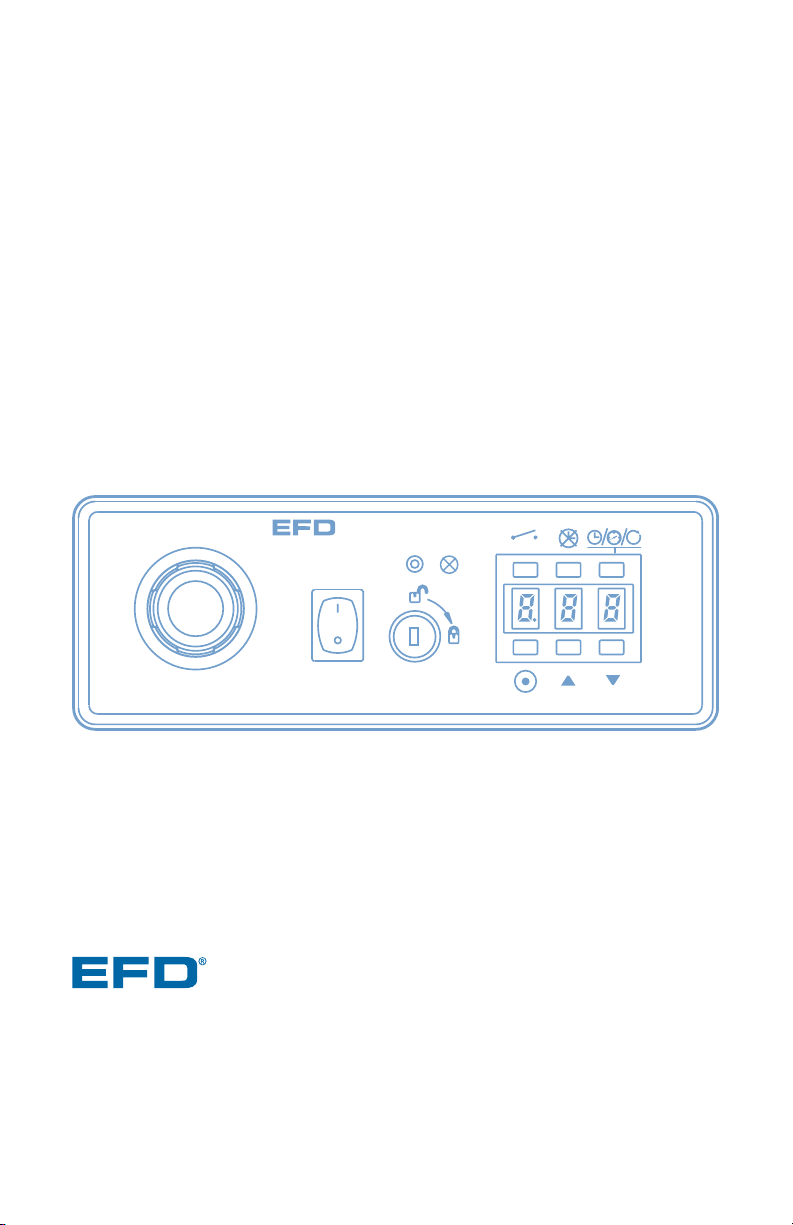
ValveMate
™
7090 Controller
Operating Manual
Electronic pdf files of EFD®manuals are also available at www.efd-inc.com/manuals.html
USA: 800-556-3484 or +1-401-434-1680
Europe: 0800 585733 or +44 (0) 1582 666334
Asia: +86 (21) 5854 2345
technical@efd-inc.com www.efd-inc.com
VALVEMATE
7090
A NORDSON COMPANY
M
M
Page 2

Introduction and Specifications ..................................3
Operating Features ..................................................4-5
Typical Setup................................................................6
Controller Setup ..........................................................7
Trial Run ....................................................................8-9
Operation Review ......................................................10
Connecting More than One 7090 Controller..............11
Input / Output Connections..................................12-13
Troubleshooting Guide ..............................................14
Schematic and Replacement Parts List ....................15
Warranty ......................................................back cover
Contents
Page 3

The ValveMate 7090 controller provides precise time, fluid pressure and
speed control, incorporating digital status displays for easy process control
and set-up. Designed for use with the 790 Series auger valves, the ValveMate
7090 features microprocessor-controlled functions, including motor start-up
acceleration limits and maximum current overload protection for extended
motor life. The controller can be operated in a continuous or pulse mode
for added flexibility. The ValveMate 7090 is simple to use and will operate
many millions of cycles without maintenance.
Introduction
Note: Specifications and technical
details are subject to engineering
changes without prior notification.
Specifications
3 / Introduction and Specifications
Size: 19 cm W x 14 cm D x 7 cm H (7.5” x 5.6” x 2.7”)
Weight: 1.5 kg (3.3 lb)
Cabinet: Aluminum
Input Voltage: Selectable 100/120/220 VAC
Fuse: T 160mA 250V
Output protection fuses (F1, F2): F 315mA 250V
Power required: 50/60 Hz 20/17 VA
Feedback Circuits: 5 to 24 VDC NC solid-state switch 250mA maximum
Initiate Circuit: 5 to 24 VDC momentary or dry contact closure
Air Input: 65 psi (4.5 bar)
Cycle Rate: Exceeds 400 per minute
Time Range: .001 to 99.9 seconds
Meets CSA and CE standards.
Page 4
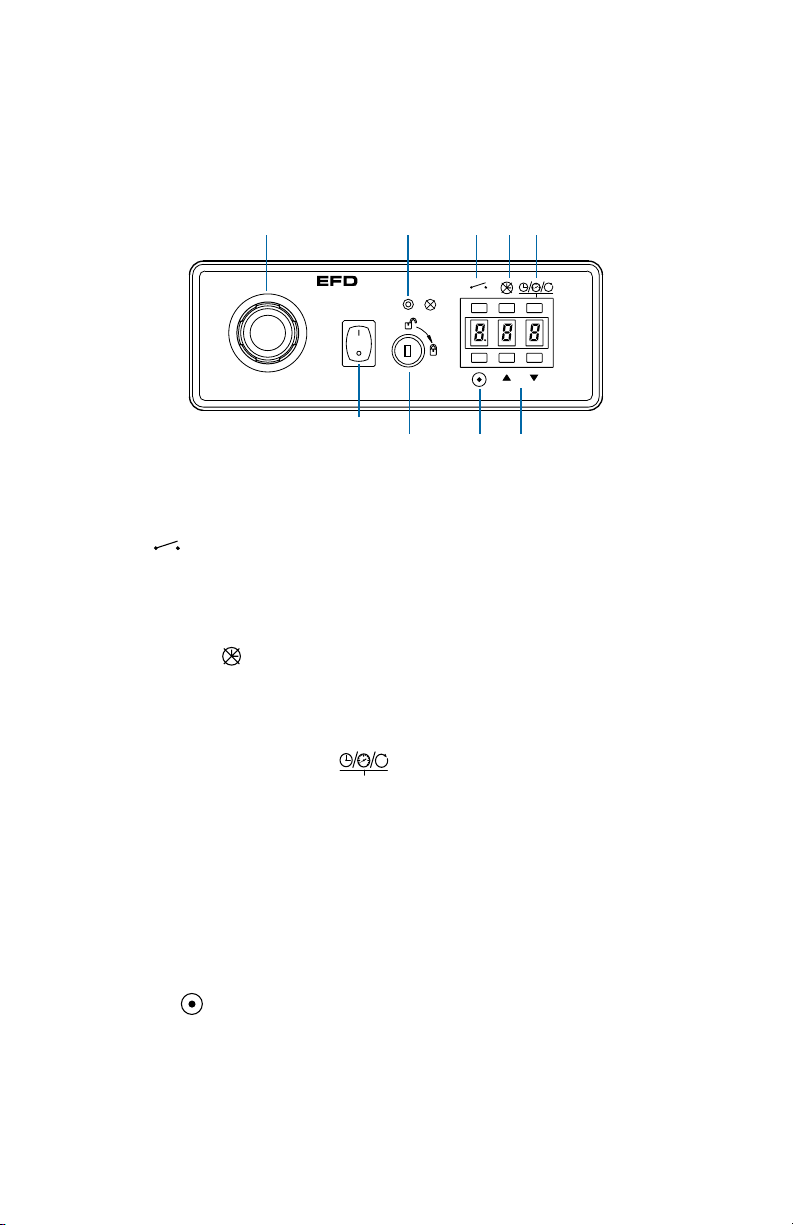
4 / Operating Features
1. Cycle
Press to initiate one complete cycle. Green lamp illuminates to indicate cycle
is on. Press again to interrupt the current cycle.
2. Time override
Press to override time control. Display will show (---). While in this mode, dispensing is manual using the cycle button or the foot pedal (optional, #2015A).
3. Time/Pressure/Motor Speed
Press to toggle the LED display between time, pressure or motor speed voltage setting.
Time is displayed in real time from .001 to 99.9 seconds. In settings less than
1.0 seconds, the decimal will not show. Pressure is identified with a flashing
“P” for pounds per square inch or an “A” for atmosphere in the left display
segment. Motor speed is identified with a rotating cursor in the left display
segment and voltage in the two right segments. Motor voltage can be set
between 10 VDC and 24 VDC.
4. Program
Press to clear display to zero. Display flashes bright/dim while in program mode.
Press cycle button and hold until required deposit is established. Each time
it is pressed, time will be added. Press program button again to exit program
mode and store new time setting.
Operating Features
M
VALVEMATE
7090
M
1
7
23
5
4
6
Power
switch
8
M
Page 5
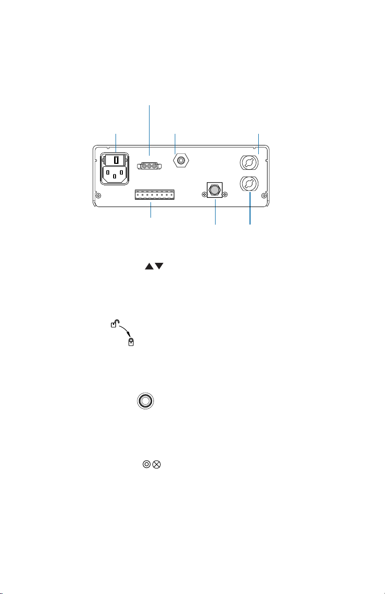
5 / Operating Features
5. Status Change Buttons
When time is displayed, press the up or down buttons to increase or
decrease setting. When pressure is displayed, use these buttons to change
display between “psi” or “bar” readout. When motor voltage is displayed, use
these buttons to increase or decrease voltage (speed) of the valve motor.
6. Control Lockout
Turn key to the right to lock-out access to program and status change buttons. Cycle, time override and display toggle buttons stay active. The key
may be removed in either the locked or unlocked position.
7. Air Regulator Control
Turn to the right to increase output pressure and to the left to decrease.
When decreasing pressure, reduce pressure below desired setting and then
increase up to target pressure. Maximum pressure is 30 psi (2.07 bar).
8. Motor Failure Indicator
Illuminates when an overload condition exceeding 135mA has shut-down the
motor controller. To reset the controller, turn the power switch off and then on
again.
Air input quick-coupler
65 psi (4.5 bar) minimum
input pressure
Reservoir pressure
pulse (white)
Foot pedal or contact
closure connection
Reservoir pressure
constant (black)
Air
exhaust
I/O interface
and motor power
connector
Input power
cord receptacle
(see page 7
for details)
Fuse T 160 mA 250V
100/120/220 VAC
50/60Hz 20/17VA
1. Initiate +
2. Initiate -
3. Output +
4. Output -
5-24 VDC or
Contact Closure
5-24 VDC
250 mA
]
]
+- - -++-+
123456 87
Air Input
65PSI
(4.5 bar)
Foot Pedal
5. Alarm +
6. Alarm -
7. Motor Output +
8. Motor Output -
5-24 VDC
250 mA
]
220
Constant
Pressure
Pulse
Pressure
M
Page 6

6 / Typical Setup
Typical Setup
To I/0 connector
pins 7&8
1. Initiate +
2. Initiate -
3. Output +
4. Output -
220
5-24 VDC or
]
Contact Closure
5-24 VDC
]
250 mA
Foot Pedal
+- - -++-+
123456 87
VALVEMATE
7090
Fuse T 160 mA 250V
100/120/220 VAC
Air Input
50/60Hz 20/17VA
65PSI
(4.5 bar)
Motor
Output
5-24 VDC
5. Alarm +
]
250 mA
6. Alarm -
7. Motor Output +
8. Motor Output -
M
Constant air
Reservoir pressure
Material
Motor input
Pulse
Pressure
Constant
Pressure
M
Page 7

7 / Controller Setup
V
A
L
V
E
M
A
T
E
7
0
9
0
M
Controller Setup
➀
2
2
0
120
1
0
0
Spare fuse
Voltage value
Cartridge window
(check voltage indicated)
➄ VALVE CONNECTION
Follow instructions in 790
Installation Guide.
➀ Mounting
Use the universal mounting bracket
(included) to mount the controller
either over or under the cabinet. The
bracket allows the controller to pivot
30° from a horizontal position. For
panel mounting, a panel mount bracket kit is available (#7000PMK).
➁ Input Power
1. View cartridge window in powercord receptacle to ensure that the
voltage is set properly.
2. If it does not match, remove the
fuse cartridge. Then remove the
fuse holder from the cartridge,
rotate the holder and position the
correct voltage to show through
the cartridge window. Reassemble
in reverse order.
3. Connect the power cord.
➂
Initiate Connection
The 7090 can be operated by applying
a 5 to 24 VDC pulse to terminal pins
1 and 2, or install a contact closure
device. Alternatively, a foot pedal may
be ordered (#2015A) and plugged into
the connector located on the rear panel.
➃
Air Input Connection
1. Connect the input air hose (supplied)
to the EFD five-micron filter regulator
#2000F755, then to air input quickconnect on the rear panel.
2. Adjust input regulator pressure to
65 psi (4.5 bar).
Page 8
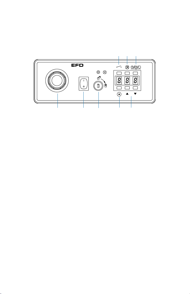
8 / Trial Run
Trial Run
1. Turn power switch to the ON position, then press toggle button until
pressure is displayed (P00).
2. Adjust pressure regulator to 8 psi (0.5 bar).
3. Press the up/down buttons to change the pressure display from psi (P)
to the metric equivalent in atmosphere (A) if preferred.
4. Place the dot-pattern card (supplied) with the purge compound under the
dispensing tip.
5. Press the time override button; display will show (---).
M
VALVEMATE
7090
M
Power
switch
➁ ➂➀
➆
➅➃
➄
Page 9

9 / Trial Run
6. Press and hold the cycle button. The motor will begin to run. Continue to
hold the button until the red purge compound begins to dispense from
the tip. Continue dispensing until valve is purged of all air.
7. To determine deposit size, press and hold the program button until the
display flashes bright to dim. Press and hold the cycle button. The valve
will begin to dispense while accumulating time on the display. Release
the cycle button, then press again; time will be added to the prior sum.
Press the program button to save the time.
8. Press the cycle button or optional foot pedal to initiate a complete cycle.
Each press on the button or pedal will repeat the same timed deposit.
Pressing the button or pedal while the valve is dispensing will stop the
cycle.
9. Press up/down buttons to make fine adjustments to the time. Press the
buttons momentarily to single step, or press and hold to scroll the time
display.
10. Press the toggle button twice to enter the motor speed mode (24 will
show on the display). Press the down button to reduce the voltage to 15.
Press the cycle button and notice the change in dispensing rate. Press
the up button to return to normal operating speed of 24.
11. Turn the key lock to the locked position. Notice that the program, up and
down buttons are not operative. The cycle, time override and toggle buttons, however, do function in the locked mode.
Page 10

10 / Operation Review
Reservoir Pressure Setting
Air pressure is used to maintain a
constant flow of fluid from the
reservoir to the auger. In general, 8
to 12 psi (0.5 bar to 0.8 bar) is
enough pressure for solder paste.
Some experimentation may be
necessary to find the correct pressure for other fluids.
Set the pressure so there is enough
to keep the auger primed at all
times, but not so much pressure
that the fluid is forced past the
auger when the valve is off.
Begin by setting the pressure at 10
psi (0.68 bar). Operate the valve in
time override mode without a dispensing tip installed until material
flows from the outlet. If after 10 seconds material does not flow, increase
pressure. The pressure setting is correct when fluid does not flow
between cycles when the valve is off.
Controlling Deposit Size
Dispense time is one of the three
means to control the output from
the 790 valve. For optimum results,
the minimum time setting should
not be less than .070 seconds.
The diameter of the dispensing tip
also affects deposit size. Reducing
the diameter reduces deposit size
by restricting the fluid flow. It is recommended to use as large a tip as
practical for the application. This
will keep the time setting low,
thereby maximizing productivity.
Motor Speed
The motor-speed control provides
fine-tuning of output. The reference
for motor speed on the LED display
is in voltage. Normal operating voltage is 24 VDC, which is the maximum speed and may be reduced to
10 VDC minimum. Reducing motor
speed will reduce the dispensing
rate.
This feature is useful when stripes
or beads of material are being dispensed. The dispensing rate may
be coordinated with the linear travel speed of the valve, as in the case
of XY motion control.
Power Off
The power switch controls both the
power and air supply within the
7090 controller. With power on, air
pressure is available to the pressure-output connectors and material reservoir. Turning the power off
closes the pressure control solenoid and exhausts all air from the
reservoir.
It is recommended to turn power off
whenever the system will not be
used for an extended period of time.
Operation Review
Page 11

11 / Connecting More Than One 7090 Controller
Connecting more than one 7090 Controller
1. Voltage Initiate Circuit
To start the dispense cycle for multiple
7090 controllers at the same time,
connect the voltage initiate circuit in
parallel as illustrated.
Note: The amperage consumption for the
voltage initiate circuit will increase with each
controller that is connected. The initiate
power supply should be sized accordingly.
2. End-of-Cycle Feedback Circuit
This circuit will ensure that the end-ofcycle signal will come from the last
7090 to complete a dispense cycle.
Connect in series as illustrated.
Note: There will be a maximum voltage
drop of 2.0 VDC through the feedback circuit
with each 7090 that is added to the series.
The input power should be adjusted for this
drop to ensure that the required voltage is
available to operate the load. Maximum
input voltage to terminals 3 and 4 must not
exceed 30.0 VDC.
2. Series circuit for Endof-Cycle Feedback
feature. A relay is illustrated as one example
for utilizing the feedback circuit.
1. Parallel circuit diagram
for Voltage Initiate.
1 2 3 4 5 6 7 8
1 2 3 4 5 6 7 8
1 2 3 4 5 6 7 8
5-24 VDC
Power source
- +
1 2 3 4 5 6 7 8
1 2 3 4 5 6 7 8
1 2 3 4 5 6 7 8
- +
5-24 VDC
Power source
Page 12

12 / Input / Output Connections
Input/Output Connections
1. Voltage Initiate Circuit
The controller may be initiated with a 5
to 24 VDC signal or contact closure
across pins 1 and 2. The signal can be
momentary (no less than 0.02 seconds) or maintained. A new cycle will
begin once power is removed and
then applied again or contacts are
opened and closed again.
2. End-of-Cycle Feedback Circuit
Upon completion of a dispense cycle,
an open collector circuit closes and
remains closed until the next dispense
cycle. This circuit can be utilized to
signal back to a host computer, start
another device in sequence or other
operations that need to be tied into
completion of the dispense cycle.
Upon closure, power from an external 5
to 24 VDC source is allowed to pass
through the circuit to operate a load.
The load illustrated is a relay, but this
could be any device that will operate
within the 5 to 24 volt range. Power
consumption of the load must not
exceed 250mA.
3. Alarm
The 7090 monitors motor current
draw. If an overload is detected, the
controller will shut-off motor power.
An open-collector circuit will close
and remain closed until the motorcontrol mode switch is turned off.
This circuit is used to signal the host
computer that a motor failure has
occurred.
Pin Function
1. Initiate +
2. Initiate -
3. Output +
4. Output -
5. Alarm +
6. Alarm -
7. Motor output +
8. Motor output -
I/O Connection
The 8 pin D connector and
internal circuitry provide
external initiate and endof-cycle feedback signal.
The pin connections are
shown below.
+- - -++-+
123456 87
Page 13

13 / Input / Output Connections
Input/Output Connections
Programmable
display
Protector
Foot pedal
100/120/
220 VAC
50/60 Hz
20/17 VA
Nonvolatile
memory
Solenoid
valve control
Power supply
controller
+ 5 VDC
+ 12 VDC
Micro-
Opto
coupler
Opto
coupler
Motor
controller
Fuse
Fuse
1
+
2
-
+
-
+
-
+
-
- +
5-24 VDC
Power source
End-of-cycle feedback circuit
Maximum load 250mA. A relay
is illustrated as one example
for utilizing the feedback circuit.
3
4
+ -
5-24 VDC
Power source
5
6
- +
5-24 VDC
Power source
7
8
Initiate circuit
5-24 VDC or
Dry Contact
Closure (5-24
VDC shown)
Motor
alarm
Motor
+
-
Page 14

Troubleshooting Guide
End-of-cycle feedback circuit
is not functioning
No power
Timer seems inoperative
If trouble cannot be corrected, or if you need further assistance,
please call us
.
In the US, call 800-556-3484. In the UK, phone 0800 585733.
In Asia, +86 (21) 5854 2345.
Trouble Possible cause and correction
Be sure that there is power at the wall
receptacle. Check the input power fuse. If
the fuse has blown, check the voltage
value in the fuse cartridge window. Be
sure that it matches the input voltage.
Ensure that the external voltage to the circuit is between 5 and 24 VDC and that the
load does not exceed 250mA.
Check to be sure time override mode is off.
Dispensing tip may be clogged, stalling the
motor. Replace tip and reset by turning
power off, then back on.
Auger is frozen. Remove fluid body and
service fluid path.
Motor has failed. Replace motor.
Motor failure indicator light is
on, indicating a current over-
load condition
14 / Troubleshooting Guide
Page 15

15 / Schematic and Replacement Parts List
Schematic and Replacement Parts List
1. 2-2002-7090 Regulator assembly
0 to 30 psi, 0 to 2.07 bar
2. 2-2003-7090B Constant solenoid assembly
3. 2-2003-7090 Control solenoid assembly
4. 2-2006DB-790 Display PCB assembly
5. 2-2017-1500 Foot pedal receptacle assembly
6. 2-2033-7060 Motor failure indicator
7. 2004B Female quick-connect – black
(not shown)
8. 2004B-W Female quick-connect – white
9. 2024-160 1/4” OD x .160” ID tubing
10. 2081A Air input quick-connect
11. 2085 1/8 NPT x 1/4 barb - low profile
12. 2086 1/8 NPT x 1/4 barb 90° - brass
13. 79012 Motor power harness receptacle
(not shown)
14. 2-7090PS Power supply
15. 7108 Exhaust muffler
16. 7109 Power switch
17. 7122 Key lock switch
18. 7111E Fuse – AC power
19. 2015A Optional foot pedal (not included)
20. 7143-01 Fuse – output protection (2)
8
1
Regulated Air
Input Air
3 1 2
18
5
10
15
12
3
14
20
11
12
16
6
17
4
9
2
Page 16

For EFD sales and service in over 30 countries,
contact EFD or go to www.efd-inc.com/contact
EFD, Inc.
East Providence, RI USA
800-556-3484; +1-401-434-1680 (outside the USA)
info@efd-inc.com www.efd-inc.com
EFD International Inc.
Dunstable, Bedfordshire, UK
0800 585733 or +44 (0) 1582 666334
Ireland 00800 8272 9444
europe@efd-inc.com www.efd-inc.com
EFD, Inc., Asia
China: +86 (21) 5854 2345
china@efd-inc.com www.efd-inc.com/cn
Singapore: +65 6896 9630 sin-mal@efd-inc.com
©2006 Nordson Corporation 7090-MAN-01 v062606
®
A NORDSON COMPANY
This equipment is regulated by the European Union under WEEE
Directive (2002/96/EC). See www.efd-inc.com for information about
how to properly dispose of this equipment.
EFD ONE YEAR LIMITED WARRANTY
All components of EFD ValveMate controllers are warranted for one year from date
of purchase to be free from defects in material and workmanship (but not against
damage caused by misuse, abrasion, corrosion, negligence, accident, faulty installation or by dispensing material incompatible with equipment) when the equipment
is installed and operated in accordance with factory recommendations and instructions. EFD will repair or replace free of charge any part of the equipment thus
found to be defective, on authorized return of the part prepaid to our factory during
the warranty period.
In no event shall any liability or obligation of EFD arising from this warranty exceed
the purchase price of the equipment. This warranty is valid only when oil-free,
clean, dry, filtered air is used.
EFD makes no warranty of merchantability or fitness for a particular purpose. In no
event shall EFD be liable for incidental or consequential damages.
 Loading...