


Window installation instructions
Part NO. YW40
March 2014

Window Installation Instructions
TABLE OF CONTENTS
General Overview
1.General notes
2.Construction notes
3.Building codes
4.Window installation
5.Perimeter anchorage
6.Vent inspection or reinstallation
Basic Installation Without Subframe or Panning
1.Installation of window units in masonry openings
2.Installation with optional “F” anchors clips
3.Installation of architectural sills
4.Installation of gravity anchors
5.Installation of side stack systems
6.Installation of mullions when not using Subframe or Panning
Hung Window Installation
1.General notes
2.Tilt window sash removal and cleaning instructions
3.Tilt window balance removal and installation
4.Side load sash - balance removal for block and tackle balances
5.Side load sash - balance removal for Class 5 balances (second generation carrier)
6.Side load sash - balance removal for Class 5 balances (third generation carrier)
Sliding Window Sash Removal
1. General notes
Casement Window Installation
1. General notes
Pivot Window Installation
1. General notes
Panning Frame Installation
1.General notes
2.Mullion installation into panning
EFCO CORPORATION 6/8/2012 |
PART NO. YW40 |

Window Installation Instructions
Subframe Installation
1.General notes
2.Mullion Installation into subframe
Screen Frame Installation
1.Project-In screen installation
2.Project-Out screen installation
3.Project-Out casement installation
4.Single hung screen installation
5.Double hung screen installation
6.Horizontal sliding window screen installation
7.Interior vertical sliding screen installation
Minimizing Condensation
Note: Please reference EFCO's "Understanding Condensation" brochure which can be obtained through your EFCO representative.
Condensation will form on any surface when unfavorable conditions (interior temperature and relative humidity and exterior temperature) are present. When the formation of excessive condensation is a concern, it is highly recommended that a design professional is utilized to perform an analysis of the shop drawings to recommend the best possible installation methods.
Please contact your EFCO representative for information on EFCO's Thermal Analysis Services.
Many current installation practices lead to an increase in the possibility of the formation of condensation. Though not all inclusive, the list of examples below illustrates conditions under which condensation is likely to occur:
1.Bridging system thermal break with non-thermally broken metal flashing or lintels that are exposed to the exterior
2.System exposure to cold air cavities
3.Interior relative humidity levels not maintained at recommended levels, see EFCO’s “Understanding Condensation” brochure
4.Inadequate separation between system and surrounding condition at perimeter
5.Product combinations during the shop drawing stage that result in bridging thermal breaks
of one or all products involved
EFCO CORPORATION 6/8/2012 |
PART NO. YW40 |

Window Installation Instructions |
- General Overview Section - |
|
|
These recommendations are for general erection procedures only. For actual job conditions, see the details on the shop drawings. For perimeter anchor type and spacing, refer to the approved shop drawings or consult the project design professional.
1. General notes
Windows are finished products and must be protected against damage. The following procedures and precautions are recommended:
A.Protection and Storage
1.Handle the material carefully.
2.Do not drop or drag from the truck to avoid racking or damage to windows or accessories.
3.Stack the windows with the directional arrows in the proper position, and allow adequate separation so the windows will not rub together.
`4. Store the windows off the ground (i.e., pallets, planks, etc.).
5.Protect against the elements and other construction trades by using a well ventilated covering.
6.Remove material from packaging if it becomes wet. Then repack materials and move to a dry location.
7.Caution: Windows are not to be used as ladders, scaffolds, or scaffold supports.
B.Check Material
1.Check all the material upon arrival for quantity and damage. Any visibly damaged material must be noted on the freight bill at the time of receipt. If a claim is required, the receiving party must process a claim with the freight carrier. If the delivery is by an EFCO truck, any damage or variance in the quantity of window units or boxes must be reported to the EFCO driver during the unloading process.
C.Cleaning Window Units
1.Cement, plaster, terrazzo, alkaline, and acid based materials used to clean masonry are very harmful to finishes and should be removed with water and mild soap immediately; otherwise, permanent staining will occur. A spot test is recommended before any cleaning agent is used.
2.For cleaning of anodized aluminum surfaces, refer to AAMA 609.1-85 Voluntary Guide Specification for Cleaning and Maintenance of Architectural Anodized Aluminum.
3.For cleaning of painted aluminum surfaces, refer to AAMA 610.79 Voluntary Guide Specification for Cleaning and Maintenance of Painted Aluminum Extrusions and Curtain Wall Panels.
Please note: The prolonged application of masking tape, duct tape, and similar products to painted aluminum surfaces will induce permanent bonding of the tape to the paint. This will cause adhesion failure between the paint and the aluminum surface when the tape is removed.
4.If a protective coating is specified, remove it from areas that require field applied sealants prior to installation.
EFCO CORPORATION 3/5/2014 |
PART NO. YW40 |
Page 1 of 7 |

Window Installation Instructions |
- General Overview Section - |
|
|
These recommendations are for general erection procedures only. For actual job conditions, see the details on the shop drawings. For perimeter anchor type and spacing, refer to the approved shop drawings or consult the project design professional.
2. Ship Open For Field Glazing
The following procedures are standard practice for EFCO corporation:
A.For all ship open window lites, EFCO will provide glazing beads, bead vinyl, and setting blocks, based upon customers noted nominal thickness and the assumption that customer will glaze in a similar manor as EFCO standard in house practices.
(With only a few exceptions most of EFCO window products are wet glazed with a silicone sealant between the glazing leg and glass.)
Account Representatives or Account Managers are requested to advise the customers of this policy in writing during the review process.
B.Customer should also understand that EFCO will not supply glazing sealants.
Setting blocks will be ship in bulk with sizes based on our standard in house practices. Adjustments to block sizes due to variations in glass size are not the responsibility of EFCO for ship open applications.
C.Customers that advise EFCO that they will be tape glazing must advise us of their actual glass thickness and dimensional allowance for tape and cap bead for appropriate bead and vinyl to be supplied. EFCO will not size for tape glazing without appropriate information. EFCO will not supply glazing tape or sealant for tape glazed method. Additional time and cost may be associated with tape glazing.
3.Construction notes
The following practices are recommended for all window installations:
A.Reference Shop Drawings
1.Check the shop drawings and installation instructions to become thoroughly familiar with the project. The shop drawings take precedence and include specific details for the project. The installation instructions are general in nature and cover the most common conditions.
B.Check Openings
1.Make certain that construction which will receive the material is in accordance with the contract documents. If not, notify the general contractor in writing and resolve differences before proceeding with your work.
C.Benchmark Layout
1.All work should start from benchmarks and/or column centers lines as established by the architectural drawings and the general contractor.
EFCO CORPORATION 3/5/2014 |
PART NO. YW40 |
Page 2 of 7 |

Window Installation Instructions |
- General Overview Section - |
|
|
These recommendations are for general erection procedures only. For actual job conditions, see the details on the shop drawings. For perimeter anchor type and spacing, refer to the approved shop drawings or consult the project design professional.
D.Plumb / Level / True
1.All materials are to be installed plumb, level, true, and in proper alignment and relation to established line grades. Products are to be installed maintaining tolerances of 1/8” in 12’-0” of length.
E.Isolate Aluminum
1.Isolate aluminum that directly contacts masonry or incompatible materials with a heavy coat of zinc chromate, plastic isolators, or bituminous paint.
F.Poured and Debridged and Thermal Strut Sections
1.Do not drill, punch, penetrate, or alter the poured and debridged thermal break or extruded thermal strut in any manner.
G.Fastening
1.Fastening means any method of securing one part to another or to adjacent materials. Due to varying opening conditions, window configurations, design pressures, and methods of anchorage (subframe, “F” anchors, etc.), perimeter fasteners are not specified in these instructions. For anchor fastening, refer to the shop drawings or consult the project design professional.
H.Blocking
1.All blocking and shims will be high strength plastic or non-corrosive materials Not by EFCO. Blocking must be of sufficient size and shape to support the frame at all anchorage locations. The blocking must prevent the anchorage fasteners from bowing, racking, twisting, or distorting the window frames and accessories in any manner.
I.Sealant
1.Sealants must be compatible with all materials they contact, including other sealant surfaces. Any sealant details shown herein, unless specifically called out to be by EFCO, are by others.
It is not EFCO Corporation’s position to select or recommend sealant or caulking types and will not assume liability or responsibility thereof. Consult the sealant supplier for recommendations relative to compatibility, adhesion, priming, tooling, shelf life, and joint design. It is the sole responsibility of the customer to perform all sealant adhesion and compatibility testing that is required by the sealant manufacturer of choice.
4. Building Codes
Glass and glazing codes governing the design and use of products vary widely. EFCO does not control the selection of product configurations, operating hardware, or glazing materials; therefore, we assume no responsibility in these areas. It is the responsibility of the owner, architect, and the installer to make these selections in strict conformity to all applicable codes.
EFCO CORPORATION 3/5/2014 |
PART NO. YW40 |
Page 3 of 7 |
Window Installation Instructions |
- General Overview Section - |
|
|
These recommendations are for general erection procedures only. For actual job conditions, see the details on the shop drawings. For perimeter anchor type and spacing, refer to the approved shop drawings or consult the project design professional.
5. Window Installation
A. The rough opening should be checked for the correct size as determined by tolerances listed in the architectural specifications and the shop drawings.
B. Establish the face of the window line at the head, sill, and jambs. This reference is arrived at by using the architectural plans, general contractor’s reference lines, and shop drawings.
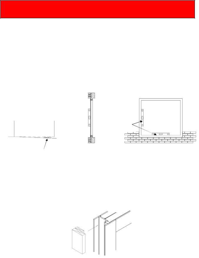
C. Determine the high point of the masonry sill using a string line or transit and shim the balance of the opening to match.
Note: For proper vent operation and drainage of windows, they must be installed plumb & level.
High Point
Plumb Frame
Shim at Anchor Locations
D. Do not fasten drapery tracks, ceiling supports, or convector covers to windows. The window must be free to expand and contract.
E.Use appropriate shim/block in the frames at perimeter anchor locations. All blocking and shims will be high strength plastic or non-corrosive materials Not by EFCO.
EFCO CORPORATION 3/5/2014 |
PART NO. YW40 |
Page 4 of 7 |

Window Installation Instructions |
- General Overview Section - |
|
|
These recommendations are for general erection procedures only. For actual job conditions, see the details on the shop drawings. For perimeter anchor type and spacing, refer to the approved shop drawings or consult the project design professional.
F. Seal all exposed perimeter joints between structure and window perimeters with a skinning, non-hardening type of sealant. Refer to the approved shop drawings for joint design.
Seal all window to window and window to accessory (subframe, panning, mullions) joints with compatible silicone sealant. Refer to the approved shop drawings for joint design.
Seal all anchor heads along the sill and 6” up the jambs.
6. Perimeter Anchorage
A. From the approved shop drawings, determine the size, type, and quantity of perimeter fasteners required. EFCO will provide fasteners for EFCO material to EFCO material only. All perimeter fasteners are Not by EFCO and should be purchased prior to arriving at the job site. (If Subframe is used, please refer to the Subframe installation sheets.)
Due to varying opening conditions, window configurations, design pressures, and methods of anchorage (subframe, “F” anchors, etc.), perimeter fasteners are not specified in these instructions. For perimeter anchor type and spacing, refer to the approved shop drawings or consult the project design professional. The design professional should analyze the anchorage system, and take into account the following information.
1.Frame dimensions and configuration of the as-installed window.
2.Material properties of the window frame.
3.Allowable tension, shear, and bending properties of the perimeter fastener.
4.Design pressure.
5.Details of the surrounding condition for the head, sill, and jambs.
6.Relative building movements and expected thermal movement of the window system.
(see detail on next page)
EFCO CORPORATION 3/5/2014 |
PART NO. YW40 |
Page 5 of 7 |
Window Installation Instructions |
- General Overview Section - |
|
|
These recommendations are for general erection procedures only. For actual job conditions, see the details on the shop drawings. For perimeter anchor type and spacing, refer to the approved shop drawings or consult the project design professional.
Substrate |
Substrate |
Edge |
Edge |
Distance |
Distance |
Bearing |
Bearing |
Substrate |
Surface |
Surface |
Thickness |
Edge |
Edge |
|
|
||
Distance |
Distance |
|
Perimeter |
|
|
|
|
Shim |
|
|
|
|
|
|
Height |
|
||
|
|
|
|
|
|||
Fastener |
|
|
|
|
|
||
|
|
|
|
|
|
||
|
|
|
|
|
Note: This sketch is a typical |
||
|
|
|
|
|
representation, other anchorage |
||
|
|
|
|
|
systems will require similar information. |
||
|
|
|
|
Frame |
|||
|
Frame |
|
|||||
|
Edge |
|
Edge |
||||
|
Distance |
|
Distance |
||||
|
|
|
|
|
|
|
|
B.Perimeter anchors should never penetrate a tank or tubular shape at a window sill. Any penetration of the frame must be visible for sealing purposes.
C.Blocking must be of sufficient size and shape to support the frame at all anchorage locations. The blocking must prevent the anchorage fasteners from bowing, racking, twisting, or distorting the window frames and accessories in any manner. Excessive shim heights could increase the prying tension and/or bending forces on the perimeter fastener. Refer to the approved shop drawings and/or design professional for project specific applications.
EFCO CORPORATION 3/5/2014 |
PART NO. YW40 |
Page 6 of 7 |

Window Installation Instructions |
- General Overview Section - |
|
|
These recommendations are for general erection procedures only. For actual job conditions, see the details on the shop drawings. For perimeter anchor type and spacing, refer to the approved shop drawings or consult the project design professional.
7.Vent Inspection or Reinstallation
A.Upon completion of the window installation, all operating vents must be checked for proper alignment and operation. All hardware must be cleaned and lubricated as necessary to provide smooth operation.
B.If the vents are removed, care must be taken to ensure the vents are reinstalled into the same frames they were removed from. It may be necessary to adjust the hinges, keepers, deflection stops, and friction arms to ensure proper sealing and locking.
EFCO CORPORATION 3/5/2014 |
PART NO. YW40 |
Page 7 of 7 |
Window Installation Instructions |
- Basic Window Installation Section - |
Completely read the General Installation Instructions and all other sections which pertain to your project before starting work. These recommendations are for general erection procedures only. For actual job conditions, see the details on the shop drawings. For perimeter anchor types and spacing, refer to the approved shop drawings or consult the project design professional.
General Procedure for the Installation of Window Units in Masonry Openings Without Subframe or Panning
EFCO Corporation will not be held liable or accept responsibility for damage to the glazing beads, window finish, or broken glass, which is a result of this type of installation.
The glazing bead may require removal and reinstallation. Care must be exercised to avoid damaging the glazing beads. (Always remove beads that run between first).
To remove the glazing bead, apply pressure to the inside lower bead edge and compress the glazing vinyl. (See arrow one). While maintaining pressure, give a slight upward movement. If the bead is really tight, it may be necessary to insert a putty knife in the crevice between the bead and frame giving a slight twisting motion as pressure is applied to the bead.
Drilling of frame and blocking by erector. Field notching of glazing beads maybe required to clear fastener heads before reinstallation of beads.
Optional
PVC Frame Filler
Field Drill Frame
Blocking by and Filler
Erector
Perimeter Seal by Erector
EFCO CORPORATION 3/5/2014 |
PART NO. YW40 |
Page 1 of 7 |

Window Installation Instructions |
- Basic Window Installation Section - |
Completely read the General Installation Instructions and all other sections which pertain to your project before starting work. These recommendations are for general erection procedures only. For actual job conditions, see the details on the shop drawings. For perimeter anchor types and spacing, refer to the approved shop drawings or consult the project design professional.
Installation with Optional “F” Anchor Clips
1.Locate the “F” anchor clips around the entire window perimeter positioned as noted on the shop drawings and or anchorage calculations by the responsible parties.
Some crimping of the anchor legs may be required to secure the anchor to the window leg during installation.
2.Move window into position in the building opening.
3.Shim tight between the masonry opening and the back of the “F” anchor with high strength plastic or non-corrosive materials Not by EFCO.
4.Install fasteners in “F” anchor per structural requirements.
Typical “F” Anchor
Not to Scale
EFCO CORPORATION 3/5/2014 |
PART NO. YW40 |
Page 2 of 7 |

Window Installation Instructions |
- Basic Window Installation Section - |
Completely read the General Installation Instructions and all other sections which pertain to your project before starting work. These recommendations are for general erection procedures only. For actual job conditions, see the details on the shop drawings. For perimeter anchor types and spacing, refer to the approved shop drawings or consult the project design professional.
Installation of Architectural Sills
1.Establish location of the architectural sill from approved project shop drawings.
2.Locate the architectural sill anchor clip positions as noted on the shop drawing and or anchorage calculations by the responsible parties.
3.Drill the anchor hole using the anchor clip as a template.
4.Shim the clips and sill as necessary to set level across the span of the opening
5.Based on the approved project shop drawings, apply a bed of grout or a high impact resistant shim for the architectural sill to rest on.
6.Hook the exterior leg of the architectural sill over the exterior leg of the anchor clip, and press the sill into a bed of grout/sealant.
Architectural Sill
High Impact Shim
or Grout
EFCO CORPORATION 3/5/2014 |
PART NO. YW40 |
Page 3 of 7 |
Window Installation Instructions |
- Basic Window Installation Section - |
Completely read the General Installation Instructions and all other sections which pertain to your project before starting work. These recommendations are for general erection procedures only. For actual job conditions, see the details on the shop drawings. For perimeter anchor types and spacing, refer to the approved shop drawings or consult the project design professional.
Installation of Gravity Anchors
HA90 Gravity Anchor
Typically gravity anchors are used for two reasons.
1.To hold one window up off another window to allow for thermal expansion. (Not usually used for vertical bays less than 10 feet tall.)
2.To hold the weight of the upper window off the lower window to keep the head from bowing or twisting.
1/4” Dia. Bolt Assembly
.312 Dia. Hole
Material: .250 steel with zinc chromate finish
Hole for anchorage to opening or mullions.
Bolt runs through both anchors and the mullion. Field drill clear hole in mullion.
Typical Gravity Anchor |
|
Typical Horizontal |
at a Mullion |
|
Stack Joint |
|
|
|
Shim as
Required
Note:
All stacks & subsills must be set in a bed of sealant to ensure a watertight seal (Interior and Exterior).
EFCO CORPORATION 3/5/2014 |
PART NO. YW40 |
Page 4 of 7 |

Window Installation Instructions |
- Basic Window Installation Section - |
Completely read the General Installation Instructions and all other sections which pertain to your project before starting work. These recommendations are for general erection procedures only. For actual job conditions, see the details on the shop drawings. For perimeter anchor types and spacing, refer to the approved shop drawings or consult the project design professional.
General Installation of Side Stack Window Systems
If side stacking is utilized, it will be necessary to either stack the units together prior to placing them in the opening, or placing them in the opening and sliding all units to one side, allowing for the last unit to be installed.
Apply a bead of silicone to the interior and exterior stack legs before assembly.
Slide units all the way to one end to allow the last window to be installed. Reposition units after the last window is stacked into provide equal spacing.
See the shop drawings for expansion joint dimensions at stacks.
Critical field seal.
To ensure a watertight seal, backbed the interior and exterior stack legs with silicone sealant before assembling windows.
After final positioning of the windows, clean off any excess sealant from the face of the window.
Do not remove sealant from the joint between the windows. If the joint has any voids, apply additional sealant completely filling the joint.
EFCO CORPORATION 3/5/2014 |
PART NO. YW40 |
Page 5 of 7 |

Window Installation Instructions |
- Basic Window Installation Section - |
Completely read the General Installation Instructions and all other sections which pertain to your project before starting work. These recommendations are for general erection procedures only. For actual job conditions, see the details on the shop drawings. For perimeter anchor types and spacing, refer to the approved shop drawings or consult the project design professional.
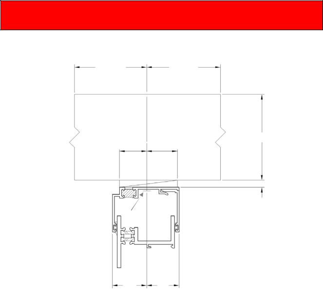
Installation of Mullions When Not Using Subframe or Panning
1.Refer to the shop drawings for the correct center line location of the mullion.
2.For elevations not using Subframe or Panning, mullions are supplied at the rough opening height plus 2” (square cut) to allow for field trimming as required
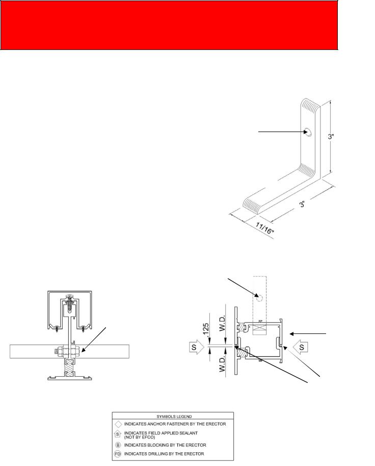
3.Set the mullion into the opening. Plumb the mullions to the opening. Fasten the mullion to the opening by using two EFCO supplied mullion anchor clips (KA20). Locate one clip at the masonry head and one at the masonry sill. Attach the clips to the opening with erector furnished fasteners, then attach the mullion to the mull anchors with EFCO furnished fasteners.
4.Back bed the window to mullion contact area with silicone sealant before installing the window, or cap seal after the window is installed.
5.Attach the mullion pressure clips to the mullion as close to the top end as possible, and then 16” on center with EFCO supplied fasteners. Spacing may need to be reduced depending on design pressure and anchorage conditions. Refer to the approved shop drawings or consult the project design professional.
Attach the 4” mullion pressure clips to the mullion at the bottom end. The 4” clip should contact the sill flashing or other adjoining horizontal surface. This bottom clip forms a water dam under some opening conditions. Seal the clip to the condition at the sill and up the sides. The screw heads on this bottom clip should also be sealed over.
6.Attach the mullion clips to each window jamb with EFCO supplied fasteners. Make sure the window jamb remains square and plumb. (Field drilling of window jambs by the erector.)
7.Field cut the vertical mullion cover to fit between the opening conditions and snap over the mullion clips.
Overall opening dimension
Check the overall frame dimensions on every 5 openings on long runs to avoid dimensional build-up.
EFCO CORPORATION 3/5/2014 |
PART NO. YW40 |
Page 6 of 7 |

Window Installation Instructions |
- Basic Window Installation Section - |
Completely read the General Installation Instructions and all other sections which pertain to your project before starting work. These recommendations are for general erection procedures only. For actual job conditions, see the details on the shop drawings. For perimeter anchor types and spacing, refer to the approved shop drawings or consult the project design professional.
Procedure A
Back seal prior to window installation.
Mullion
Mullion
Anchor
Standard mullion pressure clip as close to the top end as possible and 16” on center or as noted.
Interior cover
4” mullion pressure clip at the bottom sealed to the opening condition or flashing at the sill and up the sides. This is to maintain the sill dam height.
Spacing varies, see shop drawings.
Procedure B
Critical seal, cap bead with silicone sealant.
EFCO CORPORATION 3/5/2014 |
PART NO. YW40 |
Page 7 of 7 |

Window Installation Instructions |
- Hung Window Installation Section - |
|
|
Completely read the General Installation Instructions and all other sections which pertain to your project before starting work. These recommendations are for general erection procedures only. For actual job conditions, see the details on the shop drawings. For perimeter anchor types and spacing, refer to the approved shop drawings or consult the project design professional.
General Installation Instructions for Hung Windows
1.Install the frame plumb, level, and true. It is critical for the window operation that the jambs are parallel without bow or twist. The sash may be removed while installing the frame at the installer’s discretion. All sash removed must go back into the same frame from which it was removed. All sash that are removed should be marked accordingly to avoid confusion.
Critical
Hold dimension for full height of window +/- 1/16”
Plumb
Frame
Square |
|
|
Critical |
|
|
||
|
|
|
Straight edge check, |
|
|
|
hold bow to +/- 1/16” |
|
|
Level
Frame Elevation
2.All hung windows are to be blocked and anchored at jamb midpoints as detailed on the project shop drawings in order to prevent the jambs from bowing or twisting. The window dimension at the midpoint shall be within 1/16” of the window dimension at the head and\or sill.
3.Some hung windows are shipped with temporary spring locks attached at the sash handle rail to prevent shipping damage. When not required for the project, these locks must be removed before installing the window into the opening.
EFCO CORPORATION 3/5/2014 |
PART NO. YW40 |
Page 1 of 10 |
 Loading...