


™
Assembly and Installation Instructions Section 1
March 2013
PART NO. YS57

EFCO |
Series 5500 XTherm Curtain Wall Assembly and Installation Instructions |
|
|
|
|
2012 |
Table Of Contents |
SECTION |
PAGE |
1.General Notes and Guidelines………………………………………………………….. 3 - 4
2.Parts Identification - Fasteners and Accessories…………………………………… 5 - 7
3.Parts Identification - 7” System………………..……………………………..………… 8 - 9
4.Parts Identification - 8” System…………………..…………………………………….. 10 - 11
5.Parts Identification - Misc. Extrusions………………………………………………… 12 - 14
6.Typical Installation configurations…………………………………………………….. 15
7.Frame Assembly…………………….……………………………………….................... 16 - 18
8.Shop Applied Joint Plugs………….……………………………..…............................. 19 - 31
9.Perimeter Pocket Fillers………………………………………………..…..................... 32
10.Standard Anchorage Method……………………………………………………………. 33
11.Install Single Span Frame Components……………………………...……………….. 34 - 40
12.Install Twin Span Frame Components…................................................................. 41 - 48
13.Glazing Preparation…..…………………………………………………………………… 49 - 54
14.Vertical Splice Joints………..…...……………………………………………………….. 55 - 57
15.Exterior Cover installation........................................................................................ 58– 59
16.Reinforcement…………………………………….…….................................................
Minimizing Condensation
Note: Please reference EFCO's "Understanding Condensation" brochure which can be obtained through your EFCO representative.
Condensation will form on any surface when unfavorable conditions (interior temperature and relative humidity and exterior temperature) are present. When the formation of excessive condensation is a concern, it is highly recommended that a design professional is utilized to perform an analysis of the shop drawings to recommend the best possible installation methods. Please contact your EFCO representative for information on EFCO's Thermal Analysis Services.
Many current installation practices lead to an increase in the possibility of the formation of condensation. Though not all inclusive, the list of examples below illustrates conditions under which condensation is likely to occur:
1.Bridging system thermal break with non-thermally broken metal flashing or lintels that are exposed to the exterior
2.System exposure to cold air cavities
3.Interior relative humidity levels not maintained at recommended levels, see EFCO’s “Understanding Condensation” brochure
4.Inadequate separation between system and surrounding condition at perimeter
5.Product combinations during the shop drawing stage that result in bridging thermal breaks
|
of one or all products involved |
|
2 Page |
Note: Installation Instructions are provided as a supplement, and should be used in conjunction with |
|
the final approved shop drawings. |
|
|
|
EFCO 2012 |
Page 2 |
Instructions Installation and Assembly Wall Curtain ™XTherm 5500 Series

Series 5500 XTherm™ Curtain Wall Assembly and Installation Instructions
Section 1: General Notes And Guidelines
HANDLING / STORING / PROTECTING ALUMINUM
The following guidelines are recommended to ensure early acceptance of your products and workmanship.
A.HANDLE CAREFULLY - Store with adequate separation between components so the material will not rub together. Store the material off the ground. Protect materials against weather elements and other construction trades.
B.KEEP MATERIAL AWAY FROM WATER, MUD, AND SPRAY - Prevent cement, plaster, and other materials from contacting with and damaging the finish. Do not allow moisture to be trapped between the finished surface and the wrapping material.
C.PROTECT MATERIALS AFTER ERECTION - Wrap or erect screens of plastic sheeting over material. Cement, plaster, terrazzo, and other alkaline materials are very harmful to the finish and are to be immediately removed with soap and water. Under no circumstances should these materials be allowed to dry or permanent staining may occur.
GENERAL GUIDELINES
The following practices are recommended for all installations:
A.REVIEW CONTRACT DOCUMENTS – Become thoroughly familiar with the project. Check shop drawings, installation instructions, architectural drawings and shipping lists. The shop drawings take precedence and include specific details for the project. Shop drawings govern when conflicting information exists in the assembly and installation instructions. Note any field verified notes on the shop drawings prior to installing. EFCO assembly and installation instructions are general in nature and cover many conditions.
B.INSTALL ALL FRAMING MATERIAL PLUMB, LEVEL, AND TRUE –
Proper alignment and relationships to benchmarks and column centerlines, as established by the architectural drawings and the general contractor, must be maintained.
C.ERECTION SEQUENCE - The sequence of erection should be coordinated with the project general contractor to prevent delays and minimize the risk of material damage. Note: When preset anchors are required, coordinate and supervise anchor and insert placement with the general contractor including insert layout drawings, where required.
EFCO 2012
D.PERIMETER CONDITIONS - Verify that all job site conditions and accompanying substrates receiving the installation are in accordance with the contract documents. If deviations occur, notification must be given in writing to the general contractor and differences resolved before proceeding further with the installation in the area in question.
E.ISOLATION OF ALUMINUM - Prevent all aluminum from coming in direct contact with masonry or dissimilar materials by means of an appropriate primer.
F.SHIPMENT VERIFICATION - Verify contents of all material shipments received upon their arrival. Verify quantity and correct finishes. Notify
EFCO® immediately of any discrepancies or damage that may have occurred.
G.SEALANT - All sealant must meet [ASTM C 920, CLASS 50]. For the purposes of these instructions, sealant is to be defined as the following: SEALANT - A weather resistant, gunnable liquid filler which when cured provides a resilient, flexible (± 50% movement capability min.) air and water seal between similar and dissimilar materials.
All sealant must be compatible with all surfaces on which adhesion is required, including other sealant surfaces. All frame surfaces should be clean, dry, dust, and frost free. If a primer is required, it must be applied to clean surfaces. All perimeter substrates shall be clean and properly treated to receive sealant. All sealants and primers must be applied according to the sealant manufacturers instructions and recommendations.
This system is designed and has been tested to utilize silicone sealants at all internal joineries, i.e., joint plugs, gasket intersections, etc. It is the responsibility of the glazing contractor to submit a statement from
the sealant manufacturer indicating that glass and glazing materials have been tested for compatibility and adhesion with glazing sealants, and interpreting test results relative to material performance, including recommendations for primers and substrate preparation required to obtain adhesion. The chemical compatibility of all glazing materials and framing sealants with each other and with like materials used in glass fabrication must be established.
Maintain caulk joints as shown in the approved shop drawings. A 3/4” minimum joint is required at the head and jamb condition to accommodate installation, building movements, and thermal expansion and contraction.
Page 3

Series 5500 XTherm™ Curtain Wall Assembly and Installation Instructions
Section 1: General Notes And Guidelines
H.STRUCTURAL SEALANT JOINTS - The maximum allowable size of the glass lite is controlled by the width and depth of the structural silicone joint combined with the specified design wind load (PSF or Pa). The stress on the structural silicone must not exceed 20 PSI (137 KPa) for a 6:1 safety factor.
In order to determine the structural silicone sealant contact width or bite which adheres the glass to the frame, a calculation must be performed on a job by job basis. The formula which determines the sealant width is based on using a trapezoidal load distribution rule. This formula is expressed as follows:
Structural Sealant = |
0.5 x Short Span (ft) x Wind load (lb/ft²) |
Bite or Contact Width (in) |
Sealant Design Strength (=20 lb/in²) x 12 in/ft |
Example: Lite size is 48” x 60” and wind load for the project is 60 psf.
Structural Sealant = |
0.5 x 4’ x 60 psf |
or 120 or .500” |
Bite or Contact Width (in) |
20 x 12 |
240 |
Sealant manufacturers, as a general rule, specify the structural sealant depth (glue line) to be one half of the contact width for a 2:1 width to height ratio. The glue line should not exceed 3/8” thick nor be less than 1/4” thick. The standard joint size for Series 8800 is 1/2” x 1/4”.
I APPROVED SOLVENT OR CLEANER - Degreasing solvents, such as methyl ethyl ketone (MEK), toluene, xylene, acetone and mineral spirits can been used to remove oils or other surface contaminants, but may leave a residue film on the cleaned surfaces, which must be removed. A solution of fifty percent Isopropyl alcohol and fifty percent water is recommended for the final cleaning and preparation of substrates for sealant application. Refer to the sealant manufacturer’s application instructions, ASTM C 1193 - 09, project specifications, and local environmental regulations for requirements.
J.SETTING BLOCKS - Refer to the approved shop drawings for placement of setting blocks. Consult with the glass manufacturer for the correct setting block length for glass sizes over 40 square feet.
STRUCTURAL SEALANT JOINT DETAIL
SEALANT DEPTH (GLUE LINE)
SSG SEALANT JOINT
SPACER GASKET
 WEATHER SEAL
 STRUCTURAL SEALANT
CONTACT WIDTH
K.SECONDARY SEALANT JOINT DESIGN - The design of the secondary sealant joint is based on the 50:50 load sharing principal where the I.G. unit is comprised of two symmetrical lites of glass. The secondary sealant joint that adheres the two lites of glass together only carries half the wind load applied to the I.G. unit. Since the load is halved, the secondary sealant contact width is half that of the SSG joint. Using the example earlier for the 1/2” x 1/4” SSG joint, the secondary sealant contact width for the I.G. unit in the example is 1/4”.
Edge deletion is required on the coated surfaces (#2, #3, #4, #5, or #6) for hard or soft coated glazing products.
SECONDARY SEALANT JOINT DETAIL
1 |
2 3 |
4 |
5 6 |
|
|
STANDARD TUBULAR |
|
|
|
|
|
|
|
|
SPACERS RECOMMENDED |
|
|
|
|
|
|
|
SECONDARY SEALANT |
|
|
|
|
|
|
|
|
|
|
|
|
|
|
|
CONTACT WIDTH |
EXTERIOR |
|
|
|
|
|
|
INTERIOR |
|
|
|
|
|
|
||
EFCO 2012 |
Page 4 |

Series 5500 XTherm™ Curtain Wall Assembly and Installation Instructions
Section 2 - Parts Identification - Fasteners and Accessories
Fasteners
Profile |
Part # |
Description |
Profile |
Part # |
Description |
|
STC0 |
#13-16 X 5/8" HWH-SMS 18-8 A GM |
|
SFQ5 |
1/4"-14 X 1 1/2" HWH SHOULDERSMS 18-8 B |
|
|
|
|
|
|
|
SFZ8 |
#8-15 X 1/2" PL-FH-SMS 18-8 |
|
STT6 |
#8-18 X 9/16" PL-FH-SMS ZC TEK/2 |
|
|
|
|
|
|
|
STK4 |
#8-18 X 1/2" PL-FH-SMS 410 TEK/2 |
|
|
|
|
|
|
|
|
|
|
|
|
|
|
|
|
|
|
|
|
|
|
|
|
|
|
|
Accessories
Profile |
Part # |
Description |
Material |
|
WEP8 |
Standard 1/4” Preset Glazing Gasket |
Peroxide Cure 60 Duro Shore A EPDM |
|
|
|
|
|
WT01 |
Standard Isolator Gasket |
Shore A 90 Duro General |
|
Purpose Flexible PVC |
||
|
|
|
|
|
|
|
|
|
WEP4 |
Standard 1/4” Preset Perimeter Spacer Gasket |
Peroxide Cure 70 Duro Shore A EPDM |
|
|
|
|
|
WEP0 |
Standard 1/4” Preset SSG Spacer Gasket |
General Purpose 70 Duro Shore A Silicone |
|
|
|
|
EFCO 2012 |
Page 5 |

Series 5500 XTherm™ Curtain Wall Assembly and Installation Instructions
Section 2 - Parts Identification - Fasteners and Accessories
Accessories
Profile |
Part # |
Description |
Material |
|
HEN2 |
Standard 2” Setting Block |
Shore A 85 Duro General |
|
Purpose Black EPDM |
||
|
|
|
|
|
|
|
|
|
LC08 |
Standard Perimeter Pocket Filler |
Rigid PVC |
|
|
|
|
|
HCV9 |
Captured System Perimeter Joint Plug / Filler |
Shore 00 60 Duro Black |
|
General Purpose Silicone |
||
|
|
|
|
|
|
|
|
|
HEN1 |
Captured System Intermediate Joint Plug |
Shore 00 60 Duro Black EPDM Sponge |
|
|
|
|
|
HCV7 |
SSG System Perimeter Joint Plug / Filler |
Shore 00 60 Duro Black |
|
General Purpose Silicone |
||
|
|
|
|
|
|
|
|
|
HCV8 |
SSG System Intermediate Joint Plug |
Shore 00 60 Duro Black EPDM Sponge |
|
|
|
|
|
HGR4 |
SSG System Temporary Glazing Retainer |
Chemlon 109 - SSG - Black |
|
|
|
|
|
KX90 |
Captured System Temporary Glazing Retainer |
7089 X 2” Long (FC39), WEP8 X 4” Long, |
|
(1) STC0 Fastener |
||
|
|
|
|
|
|
|
|
EFCO 2012 |
Page 6 |

Series 5500 XTherm™ Curtain Wall Assembly and Installation Instructions
Section 2 - Parts Identification - Fasteners and Accessories
Accessories
Profile |
Part # |
Description |
Material |
|
WEP6 |
Expansion Mullion Finger Gasket |
Shore A 70 Duro General |
|
Purpose Black EPDM |
||
|
|
|
|
|
|
|
|
|
WNA3 |
Wedge Gasket use with 17S7 Glazing adaptor |
Shore A 60 Duro |
|
Santoprene |
||
|
|
|
|
|
|
|
|
|
|
|
|
|
|
|
|
|
|
|
|
|
|
|
|
|
|
|
|
|
|
|
|
EFCO 2012 |
Page 7 |

Series 5500 XTherm™ Curtain Wall Assembly and Installation Instructions
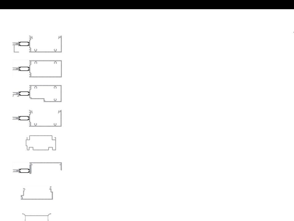
Section 3 - Parts Identification - 7” System
Profile |
Part No. |
Description |
Tooling Drawing / Cut Formulas |
|
|
|
|
|
5G12 |
7” Head / Sill / Jamb |
55XT-008 |
|
|
|
|
|
5G13 |
7” Intermediate Horizontal |
Cut to length = horizontal D.L.O. |
|
|
|
|
|
5G14 |
7” Door Header |
Cut to length = horizontal D.L.O. |
|
|
|
|
|
5G15 |
7” Intermediate Vertical |
55XT-001, 55XT-009 |
|
|
|
|
|
FL04 |
Splice for 5G15, 5G12 |
Reference FL04 Part Drawing. |
|
(Made from17S5) |
55XT-008 |
|
|
|
||
|
|
|
|
|
5G16 |
7” Expansion Vertical |
55XT-002, 55XT-006 |
|
|
|
|
|
17S2 |
7” Expansion Vertical |
55XT-003, 55XT-007 |
|
|
|
|
|
FK34 |
7” Mullion Clip |
Reference FK34 Part Drawing. |
|
(Made from 15H9) |
||
|
|
|
|
|
|
|
|
EFCO 2012 |
Page 8 |

Series 5500 XTherm™ Curtain Wall Assembly and Installation Instructions
Section 3 - Parts Identification - 7” System
Profile |
Part No. |
Description |
Tooling Drawing / Cut Formulas |
|
|
|
|
|
FK20 |
Splice for 5G16 |
Reference FK20 Part Drawing. |
|
(Made from 15L9) |
|
55XT-011 |
|
|
|
|
|
FL06 |
Splice for 17S2 |
Reference FL06 Part Drawing. |
|
(Made from 17S4) |
|
55XT-012 |
|
|
|
|
|
17S3 |
7” SSG Intermediate Vertical |
55XT-004 |
|
|
|
|
|
FL05 |
Splice for 17S3 |
Reference FL05 Part Drawing. |
|
(Made from 17S6) |
|
55XT-010 |
|
|
|
|
|
15B7 |
7” Frame Filler |
Cut to length = horizontal D.L.O. at |
|
std. head and sill. CW55-152 at |
||
|
Use with 5G12 and 5G15. |
||
|
|
|
verticals. |
|
|
|
|
|
. |
. |
|
|
|
|
|
|
. |
. |
|
|
|
|
|
|
. |
. |
|
|
|
|
|
EFCO 2012 |
Page 9 |
Series 5500 XTherm™ Curtain Wall Assembly and Installation Instructions
Section 4 - Parts Identification - 8” System
|
|
Profile |
Part No. |
Description |
Tooling Drawing / Cut Formulas |
|
|
|
|
|
|
|
|
|
5G06 |
8” Head / Sill / Jamb |
55XT-008 |
|
|
|
|
|
|
|
|
|
5G07 |
8” Intermediate Horizontal |
Cut to length = horizontal D.L.O. |
|
|
|
|
|
|
|
|
|
5G08 |
8” Door Header |
Cut to length = horizontal D.L.O. |
|
|
|
|
|
|
|
|
|
5G09 |
8” Intermediate Vertical |
55XT-001, 55XT-009 |
|
|
|
|
|
|
|
|
|
FL01 |
Splice for 5G09, 5G06 |
Reference FL01 Part Drawing. |
|
|
|
(Made from 15P7) |
55XT-008 |
|
|
|
|
|
||
|
|
|
|
|
|
|
|
|
|
|
|
|
|
|
5G10 |
8” Expansion Vertical |
55XT-002, 55XT-006 |
|
|
|
|
|
|
|
|
|
17P4 |
8” Expansion Vertical |
55XT-003, 55XT-007 |
|
|
|
|
|
|
|
|
|
FK35 |
8” Mullion Clip |
Reference FK35 Part Drawing. |
|
|
|
(Made from 15K3) |
||
|
|
|
|
|
|
|
|
|
|
|
|
EFCO 2012 |
Page 10 |
Series 5500 XTherm™ Curtain Wall Assembly and Installation Instructions
Section 4 - Parts Identification - 8” System
Profile |
Part No. |
Description |
Tooling Drawing / Cut Formulas |
|
|
|
|
|
FK22 |
Splice for 5G10 |
Reference FK22 Part Drawing. |
|
55XT-011 |
||
|
(Made from 15M2) |
|
|
|
|
|
|
|
FL03 |
Splice for 17P4 |
Reference FL03 Part Drawing. |
|
(Made from 17P6) |
|
55XT-012 |
|
|
|
|
|
17P5 |
8” SSG Intermediate Vertical |
55XT-004 |
|
|
|
|
|
FL02 |
Splice for 17P5 |
Reference FL02 Part Drawing. |
|
(Made from 17P8) |
|
55XT-010 |
|
|
|
|
|
15B2 |
8” Frame Filler |
Cut to length x horizontal D.L.O. at |
|
std. head and sill. CW55-152 at |
||
|
Use with 5G06 and 5G09. |
||
|
|
|
verticals. |
|
|
|
|
|
. |
. |
|
|
|
|
|
|
. |
. |
|
|
|
|
|
|
. |
. |
|
|
|
|
|
EFCO 2012 |
Page 11 |

Series 5500 XTherm™ Curtain Wall Assembly and Installation Instructions
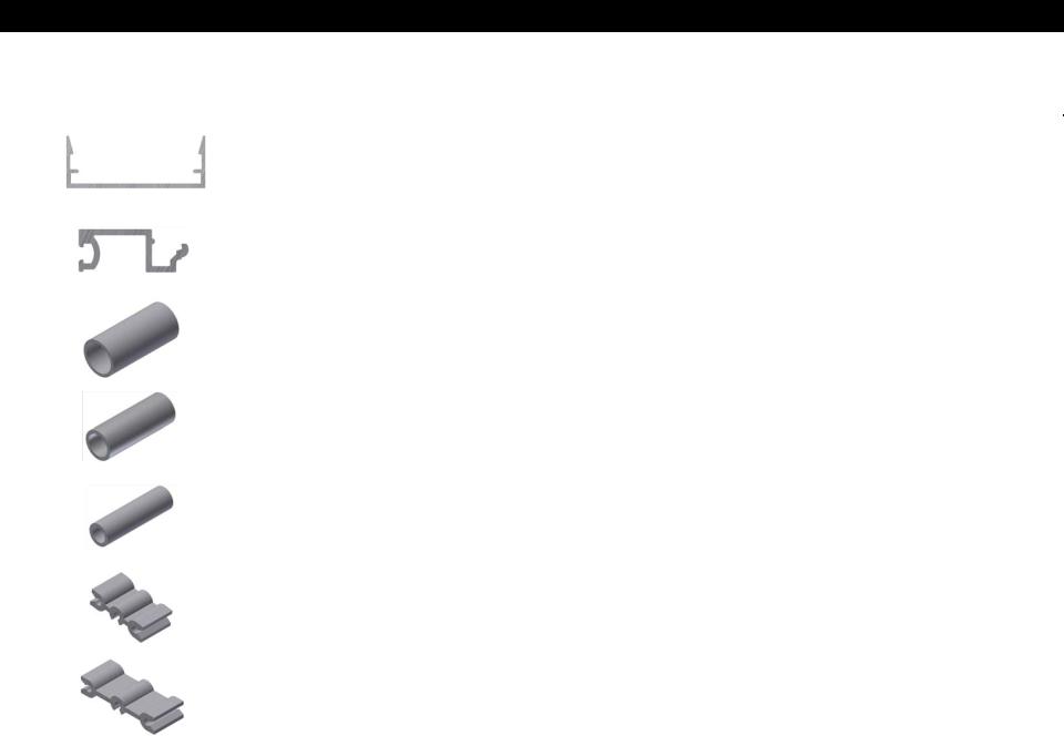
Section 5 - Parts Identification - Misc. Extrusions
Profile |
Part No. |
Description |
Tooling Drawing / Cut Formulas |
|
|
|
|
|
|
|
55XT-000974, 55XT-001649, 55XT-001679, |
|
5G11 |
Door Jamb Adapter |
55XT-000823, 55XT-000878, 55XT-000846, |
|
55XT-002487, 55XT-002520, 55XT-002523, |
||
|
|
|
55XT-002524, 55XT-002525, 55XT-002526, |
|
|
|
55XT-002533 |
|
|
|
|
|
|
|
55XT-000767, 55XT-00827,55XT-00950, |
|
5G17 |
Door Header |
55XT-000951, 55XT-00952, 55XT-002521, |
|
55XT-002522, 55XT-002527, 55XT-002528, |
||
|
|
|
55XT-002529, 55XT-002530, 55XT-002531, |
|
|
|
55XT-002532 |
|
1283 |
Snap Filler for 5G11 and 5G17 |
Cut to length x horizontal |
|
D.O. minus 1/32”. |
||
|
|
|
|
|
9155 |
Door Stop Snap Cover |
Cut to length x horizontal |
|
D.O. minus 1/32”. |
||
|
|
|
|
|
|
|
|
|
4437 |
Door Header Door Stop |
Cut to length x horizontal |
|
D.O. minus 1/32”. 55XT-000576 |
||
|
|
|
|
|
|
|
|
|
9933 |
|
Cut to length x horizontal |
|
Door Header Door Stop |
D.O. minus 1/32”. 55XT-000953, |
|
|
|
|
55XT-000954, 55XT-000605 |
|
|
|
|
|
17R1 |
Door Header Filler |
Cut to length x horizontal D.L.O. at |
|
side lite minus 1/32”. |
||
|
|
|
|
|
|
|
|
|
FWF1 |
Strike Plate Adapter |
Reference FWF1 Part Drawing. |
|
|
|
|
EFCO 2012 |
Page 12 |

Series 5500 XTherm™ Curtain Wall Assembly and Installation Instructions
Section 5 - Parts Identification - Misc. Extrusions
Profile |
Part No. |
Description |
Tooling Drawing / Cut Formulas |
|
|
|
|
|
FWF2 |
Strike Plate Adapter |
Reference FWF2 Part Drawing. |
|
|
|
|
|
FWF3 |
Strike Plate Adapter |
Reference FWF3 Part Drawing. |
|
|
|
|
|
FWF4 |
Strike Plate Adapter |
Reference FWF4 Part Drawing. |
|
|
|
|
|
FWF5 |
Strike Plate Adapter |
Reference FWF5 Part Drawing. |
|
|
|
|
|
FL08 |
2” Glazing Setting Chair |
Reference FL08 Part Drawing. |
|
|
|
|
|
KW95 |
Standard 2 1/2” Pressure Plate |
Reference KW95 Part Drawing. |
|
|
CTWL-594F |
|
|
|
|
|
|
|
|
|
|
7090 |
Standard 2 1/2” X 3/4” Cover |
Cut to frame dim. at vertical. |
|
CTWL-219A at horizontal. |
||
|
|
|
|
|
|
|
|
|
KZ54 |
2” Pressure Plate used at Door |
Reference KZ54 Part Drawing. |
|
|
Header |
|
|
|
|
|
EFCO 2012 |
Page 13 |
Series 5500 XTherm™ Curtain Wall Assembly and Installation Instructions
Section 5 - Parts Identification - Misc. Extrusions
Profile |
Part No. |
Description |
Tooling Drawing / Cut Formulas |
|
|
|
|
|
7419 |
2” x 3/4” Snap Cover used at Door |
CTWL-219A |
|
Header |
||
|
|
|
|
|
|
|
|
|
17S7 |
1” Glazing Adapter |
Cut to length |
|
Horizontal D.L.O. minus 1/16” |
||
|
(2” to 1” for 2 1/2” glazing pocket) |
||
|
|
Vertical D.L.O. Plus 1” |
|
|
|
|
|
|
|
|
|
|
FK12 |
Head Pipe Sleeve Anchor x 1 3/8” |
Reference FL12 Part Drawing. |
|
Long |
||
|
(Made from 1835) |
||
|
(1/2” Dia. Fasteners) |
|
|
|
|
|
|
|
|
|
|
|
FK81 |
Head Pipe Sleeve Anchor x 1 3/8” |
|
|
Long |
Reference FK81 Part Drawing. |
|
|
(Made from 15Y7) |
(3/8” Dia. Fasteners) |
|
|
|
|
|
|
|
|
|
|
FK82 |
Head Pipe Sleeve Anchor x 1 3/8” |
Reference FK82 Part Drawing. |
|
Long |
||
|
(Made from 15Y8) |
||
|
(1/4” Dia. Fasteners) |
|
|
|
|
|
|
|
|
|
|
|
FK18 |
Alternate Anchor x 1 3/8” Long |
Reference FK18 Part Drawing. |
|
(Made from 15H4) |
||
|
|
|
|
|
|
|
|
|
FK19 |
Alternate Anchor x 1 3/8” Long |
Reference FK19 Part Drawing. |
|
(Made from 15H5) |
||
|
|
|
|
|
|
|
|
|
|
|
|
EFCO 2012 |
Page 14 |

Series 5500 XTherm™ Curtain Wall Assembly and Installation Instructions
Section 6 - Typical Installation Configurations
The wall sections below depict the standard types of installations for the S-5500 X-Therm curtain wall. Refer to the approved shop drawings for dimensions and configurations of the frame, anchor and splice.
 Head Anchor
(Page 33 and 44)
350” MAX. MULLION LENGTH |
|
|
|
|
350” MAX. MULLION LENGTH |
|
|
|
|
||
|
|
|
|
|
|
|
|
|
|
|
|
 Head Anchor
(Page 33 and 34)
Intermediate Wind
Load Anchor (Page 42 through 44 at jamb)
(Page 46 and 47 at intermediate vertical)
 Floor Slab
350” MAX. MULLION LENGTH
350” MAX. MULLION LENGTH
Sill Anchor |
|
|
|
Sill Anchor |
|||||
(Page 33 and 34) |
|
|
|
(Page 33 and 34) |
|||||
|
|
|
|
|
|
|
|
|
|
 Head Anchor
(Page 33 and 34)
Intermediate Dead
Load Anchor (Page 42 through 44 at jamb)
(Page 46 and 47 at intermediate vertical)
 Floor Slab
Mullion Splice (Page 55)
Intermediate Wind
Load Anchor (Page 42 through 44 at jamb)
(Page 46 and 47 at intermediate vertical)
 Floor Slab
Sill Anchor (Page 33 and 34)
Single Span |
Twin Span |
Multi-Span |
EFCO 2012 |
|
Page 15 |

Series 5500 XTherm™ Curtain Wall Assembly and Installation Instructions
Section 7 - Frame Assembly
Perimeter O.G.
Jamb Mullion
Perimeter O.G.
Mullion
Perimeter O.G.
Jamb Mullion
Apply sealant in reglets of jambs at horizontal locations.
Frame assembly screws : 1/4” - 14 x 1 1/2” HWH SMS 18-8 typical.
Vertical Filler
Frame Gasket
Intermediate
Horizontal
Figure 2
Perimeter O.G.
Mullion
 Apply a bead of sealant into the snap reglet of the jambs adjacent to the head, sill, and intermediate horizontal locations (2 1/2” height) prior to snapping the filler and mullion, to seal the filler to the jamb at the glazing pockets.
Apply sealant in reglets of jambs at horizontal locations.
Frame Gasket
Vertical Filler
Figure 4
Apply sealant in reglets of jambs at horizontal locations.
Vertical Filler
Head
Horizontal Filler Apply at installation.
Horizontal Filler
Apply at installation.
Frame Gasket 
Sill 
Figure 3 |
Figure 5 |
EFCO 2012 |
Page 16 |

Series 5500 XTherm™ Curtain Wall Assembly and Installation Instructions
Section 7 - Frame Assembly
1.Using an approved solvent or cleaner, clean the frame gasket contact surfaces of all oils and other contaminants.
2.Remove the liner from the frame gaskets and apply them to the matching surfaces of the mullions ensuring the holes and edges align as required. See Figure 2, 3, 4, page 17. Butt sealing the ends of the horizontals may be used instead of applying frame gaskets, if desired.
3.Smooth out the frame gaskets onto the mullion surfaces by forcing out any remaining air bubbles.
4.Assemble the outside glazed framing members as shown below. Additional support for frames with the filler as a vertical on both sides may be needed depending on the overall frame size. See the note on page 17 for special sealant requirements at perimeter jamb, filler and horizontal intersections.
5.Carefully trim away excess gasket material around the exposed areas if required.
Perimeter O.G.
Mullion
Vertical Filler
|
Intermediate |
Head |
O.G. Mullion |
|
|
|
Clean mullion |
|
surfaces. |
Frame assembly screws : 1/4” - 14 x 1 1/2” HWH SMS 18-8 (SFQ5) typical.
Female
Expansion
Mullion
Male
Expansion
Mullion
Frame Gasket
Frame Gasket
Intermediate
Horizontal
Sill
Mullion 
Clip
|
Perimeter O.G. |
Figure 1 |
Mullion |
EFCO 2012 |
Page 17 |

Series 5500 XTherm™ Curtain Wall Assembly and Installation Instructions
Section 7 - Frame Assembly
6.Seal the jamb as shown in Figures 3 thru 5 on page 17 at the horizontal locations, and snap the perimeter jamb mullion onto the filler portion of the assembled frame.
7.Fasten the jamb to the filler with SPC9 screws at the horizontal locations. The number of fasteners will vary with the length of the perimeter jamb member and the number of horizontals in the frame, but a minimum of 1 SPC9 per jamb is required. Jamb attachment is required for left and right jamb frame assemblies.
Apply sealant in reglets of jambs at horizontal locations.
(See Figures 3 thru 5 on page 16.)
Perimeter O.G.
Jamb Mullion
Fasten the jamb to the filler with SPC9 screws at the horizontal locations. (1 location minimum).
Typical Left Jamb Frame
Figure 6
EFCO 2012 |
Page 18 |
 Loading...