


 Loading...
EVS_CSN_2_E_Rev.0
INSTRUCTION MANUAL
MULTI-STAGE DRY VACUUM PUMP
MODEL EV-S20
MODEL EV-S50
MODEL EV-S100
MODEL EV-S200
CE / SEMI / NRTL MODEL 200-220V(50/60Hz)
 Caution:
Please read and understand this INSTRUCTION MANUAL thoroughly before using this equipment.
Be sure to keep this INSTRUCION MANUAL on hand for future reference.
To Facility and Tool Manufactures:
Be sure to distribute this INSTRUCTION MANUAL to all end-user personnel actually operation this equipment.
Model ООО in this INSTRUCTION MANUAL is our model code.
ISSUED BY PRECISION MACHINERY COMPANY
EBARA CORPORATION
PM40U

Do not reproduce or reprint any portion of this manual without permission. Manufacturer reserves the right to discontinue or change any specifications or designs without notice and without incurring obligations. Model ООО in this catalog is our model code.
All rights reserved, copyright EBARA Corporation.
EBARA CORPORATION
M10U

i
Environmental Basic Policies
It is our responsibility, as people of the earth, to protect nature's irreplaceable treasures and to pass them on to future generations.
As we undertake our business activities, we will establish environmental management systems and implement ongoing improvements and reviews, while striving to promote harmony between technology and nature, prevent environmental pollution, and improve the overall results of our environmental management activities. We are aware that environmental protection and management activities are the responsibility of all managers and employees of the Corporation, and each person will demonstrate this awareness when carrying out his or her duties.
We will widely publicize these basic policies to regional societies and the general public and work to make Ebara's position on the environment clear to society in general.
EBARA CORPORATION
PM10U

ii
Safety Information
It is essential that those operating this pump should have the knowledge to identify and avoid hazardous conditions associated with the pump.
Inadequate or rash operation may cause dangerous and serious accidents.
Before installation and operation, the operator should first have a good knowledge of the pump construction, operation procedure, and its hazards.
The operator should read through this instruction manual and other documents issued by EBARA in detail.
If you have any questions on pump operation, safety, and maintenance, please do not hesitate to contact EBARA directly. Refer to Global network for contact address.
Three terms designating the level of hazard are used in this manual.
 DANGER indicates an imminently hazardous situation which, if not avoided, will result in death or serious injury.
 WARNING indicates a potentially hazardous situation which, if not avoided, could result in death or serious injury.
 CAUTION indicates an imminently hazardous situation which, if not avoided, may result in minor or moderate injury.
This term may also be used as a warning for situations liable to damage to equipment.
EBARA CORPORATION
PM10U

iii
Important Prior Warnings
 DANGER Keep out from under the pump when lifted.
Only qualified personnel shall unload and lift the pump.
 WARNING Be careful not to overturn the pump when pushing and pulling it sideways, because the width of the pump is small to its height.
 WARNING All electrical works must be performed by only a qualified electrician. All national and local electrical regulations must be observed.
 WARNING Circuit Breaker (CB) is not installed in the pump unit.
Please install Circuit Breaker (CB) based on the law and the standard in the installation region.
 WARNING Interrupt Circuit Protector (CP) before starting on wiring and maintenance work.
Do not switch on the power supply to the pump until work is completed.
 WARNING Supply N2 gas to the exhaust piping when necessary to dilute the inflammable or toxic gas up to a safe concentration.
 WARNING Purge with sufficient N2 gas before removing and washing the vacuum and exhaust piping.
Do not let inflammable, toxic or dangerous materials disperse and guard against contact with the human body.
Always work in a location with an escape route in an emergency.
 WARNING Do not use the pump for another process without a previous overhaul. Gases or reaction products remaining in the pump will react and lead to accidents with the formation of large amounts of products.
EBARA CORPORATION
PM10U

iv

 WARNING Check for gas leaks after installing and maintaining the piping. Gas leaks will result in the discharge of harmful and dangerous substances and in abnormal reactions due to the ingress of air into the pump. When checking for gas leaks by pressurization, please pressurize by less than 0.05 MPa into the purge port and do check.
 WARNING Do not alter the pump member nor change any parts without the EBARA's consent or approval.
 WARNING The pump casing and exhaust piping become extremely hot during operation and for some time after stopping.
Be sure that pump and exhaust piping do not come in contact with humans or inflammable substances.
Do not remove the pump cover during operation.
 WARNING Check Safety Interlock functions periodically (every 6 months) to confirm the interlocks will work correctly.
 CAUTION Disposal of process by-products shall be strictly in accordance with all local and national environmental and safety regulations.
 CAUTION Disposal of Printed circuit board containing Lithium battery shall be strictly in accordance with all local and national environmental and applicable regulations.
WARNING In designing the dry pumps, Ebara does not assume risks caused by hazardous chemical reactions resulted from simultaneous injection or mixture of multiple process gases in the pumps, and the pump is not equipped with a protection against the dangers from such pump usage. The tool suppliers and users must pay attention not to simultaneously inject or mix those gases.
EBARA CORPORATION
PM10U

v
 WARNING Do not perform a withstand voltage test.
Failure to comply could result in damage to the sensitive devices.
 CAUTION Never operate the pump without pump cover for safety.
EBARA CORPORATION
PM10U
vi
Following safety warning labels are attached to pump covers.
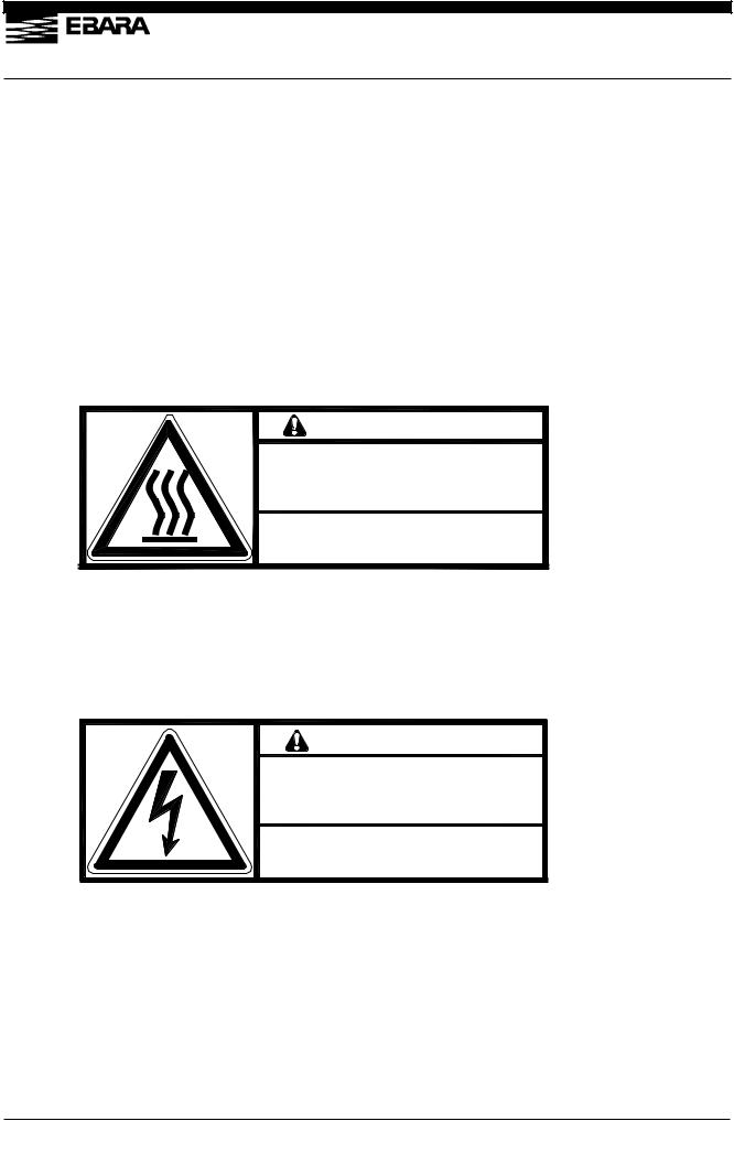
1.High temperature warning
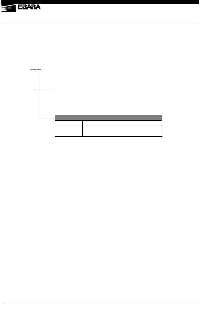
2.Hazardous voltage warning
3.Hazardous materials warning
4.Electric charge mark
5.Hazardous weight danger
1.High temperature warning
Hot surface may burn or cause injury.
Allow the piping and casing to cool before servicing.
WARNING
Hot Surfaces
Will burn skin on contact.
Allow piping and casing to cool
Before servicing
C-7110-312-0001
2.Hazardous voltage warning
Hazardous Voltage may shock, burn, or cause death. Turn power off and lockout before servicing.
WARNING
Hazardous Voltage
Contact will cause injury or death by electrical shock. Disconnect
line power before servicing.
C-7110-313-0001
EBARA CORPORATION
PM10U

vii
3. Hazardous materials warning
In case of hazardous materials are handled. Run the pump only with N2 gas purge before servicing. Take adequate measures against dangerous reaction and contact with human body.
WARNING |
|
|
Hazardous Materials
Exposure to air may cause spontaneous fire or explosion. Inhalation or skin absorption will cause severe injury or death by poisoning.
Purge thoroughly with nitrogen for at least 30 minutes before servicing. Use personal protective equipment appropriate to the materials to prevent exposure.
C-7110-314-0001
4.Electric charge mark
5.Hazardous weight danger
Heavy weight may cause severe injury or death due to overturning or falling pump. Keep out from under the lifted pump.
Raise all adjuster-feet fully when moving.
Heavy Object
Can cause impact injury through falling or tipping.
Use appropriate, properly rigged lifting equipment and keep from under suspended pump. Raise all adjuster feet fully when moving.
C-7110-316-0001
EBARA CORPORATION
PM10U

viii
EBARA CORPORATION
PM10U
ix
EBARA CORPORATION
PM10U

x
Safety Interlocks
 WARNING Check Safety Interlock functions periodically (every 6 months) to confirm the interlocks will work correctly.
NITROGEN FLOW LOW
A normally open flow switch breaks when nitrogen supply to the pump (oil bearing(s) and inter stage injection) drops below its factory set point, opening the motor starter relay(s) and shutting down the pump. Restoration of sufficient nitrogen flow permits restarting the pump.
MOTOR OVERLOAD
Motor thermostat protect the pump motor from overheating due to extended current draws in excess of the motor rating. Under a persistent overload condition, motor thermostat opens a contact, which interrupts the motor run circuit. A brief cool down interval permits restarting the pump.
EBARA CORPORATION
PM10U

PM10U
CORPORATION EBARA
POWERSUPPLY |
|
|
|
|
|
|
||
3φ3W 200VAC 50Hz |
|
|
|
|
LCDcontroller |
|
||
3φ3W 200-220VAC 50/60Hz |
|
|
|
|
|
|
||
|
|
|
|
|
|
|
RESET |
|
R |
S |
T |
|
|
|
|
|
|
E |
|
|
User side |
|
|
|
|
|
|
|
|
|
|
|
|
|
|
|
|
|
(EXT.IL) |
|
|
|
||
(CN_A) |
|
|
|
|
|
|
|
|
A |
B |
C |
|
|
|
|
|
|
|
|
|
Pump side |
|
|
|
|
|
E |
|
|
|
|
|
|
|
|
|
|
CP |
|
|
|
|
|
|
|
|
|
(CN_11) |
1 |
2 |
[ INTERLOCK BOARD ] |
|
|
|
|
[ UL1077 ] |
|
|
|
|
CPU |
CPU |
|
|
|
|
|
|
|
||
|
|
|
|
|
|
(CN_1) |
(CN_8) |
|
|
|
|
|
|
|
1 |
|
|
|
|
|
|
|
|
1 |
|
|
|
|
|
|
|
|
|
|
|
|
|
|
|
|
|
2 |
2 |
|
|
|
|
|
|
|
|
|
|
NOIZE |
|
|
|
|
|
[ DVP401 ] |
[ DVP402 ] |
|
|
|
|
|
X1 |
|
|||
|
|
|
|
|
|
|||
FILTER |
|
|
|
|
|
|||
|
|
|
|
|
|
|||
E |
|
|
|
|
|
|
|
|
|
|
|
+12V |
|
|
|
|
|
R |
S |
T |
|
|
|
|
|
|
|
|
|
(CN_8) 1 |
2 |
|
|
|
|
[ MP MOTOR DRIVER ] |
[ DVP414] |
|
|
|
|
|
||
|
|
|
|
|
|
|||
|
|
|
(CN_1) |
|
|
|
|
|
|
|
B1 |
3 |
|
|
|
|
|
|
|
|
1 |
|
|
|
|
|
E |
|
|
(MP-TH) 1 |
3 |
|
|
|
|
|
|
CPU |
|
|
|
|
|
|
U |
V |
W |
|
|
|
|
|
|
E |
|
|
|
|
|
|
|
|
|
|
|
MP |
|
|
|
|
|
|
M |
|
MOTOR |
|
|
|
|
|
|
|
THRMO |
|
|
|
|
||
|
|
|
|
|
|
RS485communication |
|
|
S20)-Schematic(EV Interlock
xi

PM10U
|
|
|
|
POWERSUPPLY |
|
|
|
|
|
|
|
||
|
|
|
|
3φ3W 200VAC 50Hz |
|
|
|
|
|
LCDcontroller |
|
||
|
|
|
|
3φ3W 200-220VAC 50/60Hz |
|
|
|
|
|
|
|
||
|
|
|
|
|
|
|
|
|
|
|
|
RESET |
|
|
|
|
|
R |
S |
T |
|
|
|
|
|
|
|
|
|
|
|
E |
|
|
User side |
|
|
|
|
|
|
|
|
|
|
|
|
|
|
|
|
|
|
|
|
|
|
|
|
|
|
|
(EXT.IL) |
|
|
|
|
||
|
|
|
|
(CN_A) |
|
|
|
|
|
|
|
|
|
|
|
|
|
A |
B |
C |
|
|
|
|
|
|
|
|
|
|
|
|
|
|
Pump side |
|
|
|
|
|
|
|
|
|
|
E |
|
|
|
|
|
|
|
|
|
|
|
|
|
|
|
CP |
|
|
|
|
|
|
|
|
|
|
|
|
|
|
(CN_11) |
1 |
2 |
[ INTERLOCK BOARD ] |
|
|
|
|
|
|
|
|
|
[ UL1077 ] |
|
|
|
|
|
CPU |
CPU |
|
|
|
|
|
|
|
|
|
|
|
|
||
|
|
|
|
|
|
|
|
|
|
|
(CN_1) |
(CN_8) |
|
|
|
|
|
|
|
|
|
|
|
|
1 |
|
|
|
|
|
|
|
|
|
|
|
|
|
1 |
|
|
|
|
|
|
|
|
|
|
|
|
|
|
|
|
|
|
|
|
|
|
|
|
|
|
|
2 |
2 |
|
|
|
|
|
|
|
|
|
|
|
|
|
|
|
|
|
|
|
NOIZE |
|
|
|
|
|
|
[ DVP401 ] |
[ DVP402 ] |
|
|
|
|
|
|
|
|
|
|
X1 |
|
|||
|
|
|
|
|
|
|
|
|
|
|
|||
|
|
|
|
FILTER |
|
|
|
|
|
|
|||
|
|
|
|
|
|
|
|
|
|
|
|||
|
|
|
|
E |
|
|
|
|
|
|
|
|
|
|
|
|
|
|
|
|
+12V |
|
|
|
|
|
|
|
R |
S |
T |
R |
S |
T |
|
|
|
|
|
|
|
|
|
|
|
|
|
|
(CN_8) 1 |
2 |
|
(CN_9) 1 |
2 |
|
|
|
[ BP MOTOR DRIVER ] |
[ MP MOTOR DRIVER ] |
[DVP414] |
|
|
|
|
|
|
||||
|
|
|
|
|
|
|
|
||||||
|
|
|
|
|
|
|
(CN_1) |
|
|
|
|
|
|
|
|
|
|
|
|
B1 |
3 |
|
|
|
|
|
|
|
|
|
|
|
|
|
1 |
|
|
|
|
|
|
|
E |
|
|
E |
|
|
(MP-TH) 1 |
3 |
(BP-TH) 1 |
3 |
|
|
|
|
|
|
CPU |
|
|
CPU |
|
|
|
|
|
|
|
EBARA |
U |
V |
W |
U |
V |
W |
|
|
|
|
|
|
|
E |
|
|
E |
|
|
|
|
|
|
|
|
|
|
|
|
|
|
|
|
|
MP |
|
|
BP |
|
|
|
|
|
M |
|
|
M |
|
MOTOR |
|
MOTOR |
|
|
||
|
|
|
|
|
THRMO |
|
THRMO |
|
|
||||
CORPORATION |
|
|
|
|
|
|
|
|
|
|
RS485communication |
|
|
|
|
|
|
|
|
|
|
|
|
|
|
|
|
S200)-EV S100/-EV S50/-Schematic(EV Interlock
xii

xiii
Standard Limited Warranty
The terms of this Warranty limit the liability of EBARA CORPORATION. Please read it carefully.
Duration
For new pumps, the Warranty period shall be one (1) year from the date of commencing operation by user or 18 months from shipment by EBARA, whichever comes first. This Warranty does not apply to service beyond these time periods.
For overhauled pumps, the warranty period shall be six (6) months from shipment by EBARA.
Coverage
For the duration of the Warranty period, EBARA warrants this ESA pump from failure due to defects in materials or workmanship. For such failures, EBARA will, at its option, either replace or repair the pump free of charge
Such repair or replacement will not extend the duration of the warranty beyond the original period.
For repairs not covered under this Warranty, EBARA will charge the customer for parts and labor.
Exclusions and Limitations
This Warranty does not cover the following:
1.Failure due to operating the pump in a manner or under conditions other than as described in the instruction manual.
2.Failure due to corrosion, byproducts or foreign material entering the pump.
3.Failure due to fire, flood, earthquake, Acts or God, Acts of War or other circumstances beyond EBARA’s control.
Disassembly or repair of the pump by parties other than EBARA or EBARA-authorized suppliers will void this Warranty.
EBARA’s liability is limited to repair or replacement of the pump under Warranty. EBARA accepts no liability for consequential damages, including injury to personnel and damage to facilities, tools or product.
EBARA makes no Warranty of merchanability, beyond statuatory requirements, or of fitness for a specific purpose.
EBARA CORPORATION
PM10U

xiv
EBARA CORPORATION
PM10U

|
|
|
|
|
|
|
|
|
xv |
|
|
|
Contents |
|
Environmental Basic Policies .......................................................... |
i |
|||
Safety Information.................................................................................. |
ii |
|||
Important Prior Warnings ................................................................. |
iii |
|||
Safety Interlocks ..................................................................................... |
x |
|||
Standard Limited Warranty ................................................................... |
xiii |
|||
Contents |
........................................................................................................ |
xv |
||
1. |
Foreword................................................................................................... |
17 |
||
2. |
Introduction ............................................................................................ |
17 |
||
|
2.1 |
Introduction ........................................................................................ |
17 |
|
|
2.2 |
Environmental .....................................................................Concerns |
3 |
|
3. |
Product ...................................................................................Description |
4 |
||
|
3.1 |
Outline................................................................................................... |
4 |
|
|
3.1.1 ................................................................................ |
Pump Module |
4 |
|
|
3.1.2 ........................................................... |
N 2 Gas (EV - S**P / EV - S**N) |
4 |
|
|
3.1.3 ............................................................................... |
Cooling Water |
5 |
|
|
3.1.4 .......................................................................................... |
Exhaust |
5 |
|
|
3.2 |
Control ....................................................................................System |
5 |
|
|
3.2.1 ......................................................................................... |
Warning |
5 |
|
|
3.2.2 ............................................................. |
Operation Status Control |
6 |
|
|
3.3 The ....................................................................way of pump moving |
6 |
||
|
3.3.1 .................................................................................... |
Preparation |
6 |
|
|
3.3.2 ............................................................................. |
Moving method |
7 |
|
|
3.4 Release ...................................and shut off residual internal energy |
8 |
||
|
3.4.1 .......................................Electrical Power - Lockout and Tagout |
8 |
||
|
3.4.2 ................................................................................ |
Cooling water |
9 |
|
|
3.4.3 .................................................................................. |
Nitrogen (N 2 ) |
9 |
|
|
3.4.4 ..................................................................... |
Returning to Service |
9 |
|
|
3.5 |
Detailed ......................................................................Specifications |
10 |
|
|
3.5.1 Model .........................................................................Description |
10 |
||
|
EV-S20 ..................................................................OUTLINE DRAWING |
15 |
||
|
EV-S20P ............................................./ EV-S 20N OUTLINE DRAWING |
16 |
||
|
EV-S50 ..................................................................OUTLINE DRAWING |
17 |
||
|
EV-S50P ............................................../ EV-S50N OUTLINE DRAWING |
18 |
||
|
EV-S100 ................................................................OUTLINE DRAWING |
19 |
||
|
EV-S100P ........................................./ EV-S 100N OUTLINE DRAWING |
20 |
||
|
EV-S200 ................................................................OUTLINE DRAWING |
21 |
||
EBARA CORPORATION
PM10U

|
|
|
|
|
|
|
|
|
|
|
|
xvi |
|
|
EV-S200P / EV-S 200N OUTLINE DRAWING......................................... |
22 |
|
|||
|
Performance Curve ................................................................................ |
23 |
|
|||
4. |
Installation ................................................................................................ |
26 |
|
|||
|
4.1 |
Movement and Fixation ..................................................................... |
26 |
|
||
|
4.1.1 |
Location....................................................................................... |
26 |
|
||
|
4.1.2 Caster and adjustment foot ....................................................... |
26 |
|
|||
|
4.1.3 |
Pump Fixation (Option) .............................................................. |
27 |
|
||
|
4.2 |
Piping.................................................................................................. |
32 |
|
||
|
4.2.1 Vacuum and Exhaust Piping...................................................... |
32 |
|
|||
|
4.2.2 |
Cooling Water Piping.................................................................. |
33 |
|
||
|
4.2.3 |
N2 Gas Piping .............................................................................. |
34 |
|
||
|
4.3 |
Electrical Wiring................................................................................. |
35 |
|
||
|
4.3.1 |
Power Supply Wiring.................................................................. |
36 |
|
||
|
4.3.2 |
Control Signal Wiring ................................................................. |
37 |
|
||
|
4.3.3 Additional Emergency Off (EMO) input..................................... |
41 |
|
|||
|
4.4. Power Supply for the Options (Connector CN-C) ............................. |
42 |
|
|||
5. |
LCD Controller.......................................................................................... |
43 |
|
|||
|
5.1 |
LCD Outline ........................................................................................ |
43 |
|
||
|
5.2 |
LCD Indication.................................................................................... |
44 |
|
||
|
5.3 |
Setting the operational mode............................................................ |
48 |
|
||
|
5.3.1 Setting the pump operation control mode................................ |
50 |
|
|||
|
5.3.2 Setting the DIP switch ................................................................ |
50 |
|
|||
|
5.3.3 Setting the pump running mode................................................ |
51 |
|
|||
|
5.3.4 Setting the rotational speed in the S. ENERGY mode ............. |
51 |
|
|||
|
5.3.5 Setting the rotational speed in the S. ENERGY mode................ |
52 |
|
|||
|
5.3.6 Setting the pump N2 flow low warning threshold ...................... |
52 |
|
|||
|
5.3.7 Setting the Water flow low warning threshold............................ |
53 |
|
|||
|
5.3.8 Setting the Back Pressure high warning threshold ................... |
53 |
|
|||
|
|
|
|
54 |
|
|
|
5.4 |
Dip Switch |
|
|||
|
5.5 |
DIP Switch setting display ................................................................ |
57 |
|
||
6. |
Operation .................................................................................................. |
59 |
|
|||
|
6.1 |
Before Starting ................................................................................... |
59 |
|
||
|
6.2 |
START/STOP ...................................................................................... |
62 |
|
||
|
6.2.1 LOCAL (Pump Side) Start/Stop ................................................. |
63 |
|
|||
|
6.2.2 |
REMOTE Start/Stop .................................................................... |
63 |
|
||
|
6.2.3 |
COMMUNICATION Start/Stop .................................................... |
64 |
|
||
|
6.3 |
Operation when momentarily power failure happens..................... |
64 |
|
||
EBARA CORPORATION
PM10U

|
|
|
|
|
|
|
|
|
xvii |
|
|
|
||
7. |
Maintenance and Inspection ................................................................... |
64 |
||
|
7.1 |
Internal energies ................................................................................ |
64 |
|
|
7.1.1 |
Power source .............................................................................. |
64 |
|
|
7.1.2 |
Cooling water .............................................................................. |
64 |
|
|
7.1.3 |
Nitrogen gas................................................................................ |
64 |
|
|
7.2 |
Routine Inspection............................................................................. |
65 |
|
|
7.3 |
Vacuum and Exhaust Piping............................................................. |
66 |
|
|
7.4 |
Lubricating Oil.................................................................................... |
68 |
|
|
7.5 |
Spare (Maintenance) Parts List......................................................... |
70 |
|
|
7.6 |
List of wastes during maintenance .................................................. |
71 |
|
|
7.7 |
Overhaul ............................................................................................. |
71 |
|
8. |
Disconnection and Transportation......................................................... |
72 |
||
9. For SEMI S2 standard................................................................................. |
74 |
|||
10. Troubleshooting ....................................................................................... |
75 |
|||
|
10.1 Troubleshooting (1) Basic trouble .................................................... |
76 |
||
|
10.2 |
Troubleshooting (2) WARNING....................................................... |
77 |
|
|
10.3 |
Troubleshooting (3) ALARM ........................................................... |
78 |
|
|
10.4 |
Troubleshooting (4) Option............................................................. |
79 |
|
EBARA CORPORATION
PM10U

P.1
1.Foreword
We appreciate that you have selected an EBARA Model EV-S series dry vacuum pumps. These pumps have been manufactured with much care and attention so that it can be operated safely and satisfactorily.
Incorrect operation will result in lack of performance and cause accidents and injuries to personnel.
[ NOTE ] This instruction manual contains all necessary information on operation and maintenance of the pump.
Be sure to operate the pump correctly in accordance with these instructions to ensure a long service life.
Keep this instruction manual in a suitable place for immediate reference whenever needed.
2.Introduction
2.1Introduction
Check the following items on receipt of the pump package.
(1)Check that the nameplate affixed to the outer cover of the pump to confirm that the pump supplied agrees with your order.
Check the accessories against the packing list and the previously submitted drawings and documents to confirm that the all ordered accessories have been supplied.
(2)Check whether damage has occurred or screws/bolts have worked themselves loose in transit.
 CAUTION Notify EBARA without delay when damage is discovered or when components are missing. Do not use when a leak is present as this will result in accident.
(3)Store the pump in a dry and clean place if it is not installed at once after delivery.
Temperature |
: |
5-40°C |
Humidity |
: |
80% or less |
(4) Pump must be placed in an upright position.
EBARA CORPORATION
PM10U
P.3
2.2Environmental Concerns
Handling or operating the unit other than specified may induce adverse impacts on the environment. Follow the descriptions below to handle, operate, and maintain the unit.
(1)Ask an authorized waste-disposal company to dispose packing materials from uncrating according to laws and ordinances applicable to the waste.
(2)Failure to do the unit maintenance (including overhaul) may trigger accidents causing injury or death, unit troubles, or environmental pollution. Plan the maintenance and perform it periodically to operate the unit efficiently.
(3)To dispose the unit, follow effective laws and ordinances applicable in the area where the unit is installed.
(4)To dispose the lubricant oil and chemicals, follow effective laws and ordinances applicable in the area where the unit is installed.
 WARNING If the pump becomes damaged during shipment or if parts are missing, immediately contact EBARA. If a leaking or damaged product is used, an accident resulting in injury or death could occur or the product could become further damaged. Even if leakage occurs, take measures to ensure they will not be directly discharged from the site, as such leakage also wastes resources.
 CAUTION If the product is not to be immediately installed, store it in a clean, dry location.
EBARA CORPORATION
PM10U

P.4
3.Product Description
3.1Outline
These pumps have a compact design and includes various sensors and controls to enhance reliability and operation.
3.1.1Pump Module
The pump is Roots type vacuum pump which rotates a pair of non-contact multi-stage rotors synchronized by timing gears.
The timing gears and bearings are enclosed in a compartment which is independent of the casing. For lubrication Perfluoro-Polyether (PFPE) oil and grease are used.
The pumps of this series are factory filled with lubrication oil. Use only the recommended lubrication oil grades shown in specification Table 3.1 for replenishing or replacing.
3.1.2N2 Gas (EV-S**P / EV-S**N)
Introduce nitrogen gas to dilute the hazardous gases to an unharmful level. Properly connect the nitrogen gas line to the purge port provided according to the instructions in Table 3.1 and the descriptions in Section 4.2.3. In the cases the gas concentration may become higher than the specified for safe gas exhaust, introduce the nitrogen gas to lines to the exhaust outlet. The tool user shall provide the purge port for this purpose.
N2 gas is also required to supply to seal the shaft section. This protects the penetration to bearing section, such as corrosive gas. To reduce pump corrosion due to process gas or accumulation of reaction by-products, N2 gas is supplied to each pump component as dilution purge gas. Stopping the dilution N2 with a selector valve can save N2 gas, when process does not produce corrosion and reaction by-products. The correct amount of N2 gas is supplied for those two types of purge operation, by adjusting the regulation pressure to the specified value. The nitrogen gas selector is locating on the right side of the unit, facing the utility connectors. It is under the outer cover.
EBARA CORPORATION
PM10U

P.5
3.1.3Cooling Water
Because the pump compresses gas from a vacuum to atmospheric pressure, compression heat is generated. Therefore cool the pump with cooling water. The cooling water connector takes the form of a coupler for easy connection and disconnection.
3.1.4Exhaust
A check valve is built into the pump unit to prevent reverse flow of gas from the exhaust through the pump to the vacuum chamber when pump is stopped.
3.2Control System
These pumps have a built-in unit consisting of a Circuit Protector (CP), Noise Filter (NF), control source.
To improve reliability and safety, the condition of each utility and pump section is monitored by a sensor.
During pump operation all operating conditions are monitored, including power supply, cooling water flow, N2 gas flow, casing and motor coil temperature, motor speed, and electric power for motor.
Continuous operation is possible when there is a momentarily power failure (170V or less) of 1 sec or less.
3.2.1Warning
To assure the reliability of the pump as a vacuum exhaust system, the pump protection system generates two levels of alarm WARNING and ALARM.
A WARNING signal is generated when pump operation exceeds the normal range. It therefore only draws attention that the normal operating values are not adhered to but does not signify that danger is imminent. The pump will continue to operate in this condition.
An ALARM signal output is generated and the pump will stop automatically when the upper mechanical safety limit is reached during pump operation.
EBARA CORPORATION
PM10U

P.6
When an ALARM output is suddenly generated, while the plant unit is operational, a WARNING signal will be generated to ensure that the plant operation is not discontinued. This enables the operator to check the pump after the equivalent of one cycle has been completed.
Be sure to contact EBARA Corporation for details on checking the WARNING and ALARM setting conditions.
3.2.2Operation Status Control
The sensor data are displayed on the LCD provided on the controller to facilitate operation status control and daily inspection.
All WARNING and ALARM signals are displayed on the LCD. For remote operation and monitoring, the signals are available as individual and group outputs.
3.3The way of pump moving
3.3.1Preparation
Before pump moving, all adjuster feet shall be raised fully at four places.
In case of being not raised fully, pump may be tripped over by obstacle on floor.
EBARA CORPORATION
PM10U

P.7
3.3.2Moving method
Move pump slowly by pushing eye bolt toward direction A. Be sure not to be caught by toes. If pump needs to be moved toward direction B in order to be set at a corner or narrow spaces, two persons shall move the pump by pushing its terminal portion alternately as directed below.
B
 A
A
If pump needs to be moved on steps or ditches, spread steel plate or the like which can sustain the pump weight over the steps / ditches and pump shall be moved on it by two persons with care.
 Steel Plate
If pump should lose its balance when moving and start tripping over, never try to sustain the pump, get away from the pump immediately.
EBARA CORPORATION
PM10U

P.8
3.4Release and shut off residual internal energy
 WARNING To avoid dangers potentially encountered during maintenance, transportation or storage, follow instructions below to shut off power.
 WARNING Capacitors within the control panel retain residual energy after interruption of power supply. Wait five (5) minutes after shutting off breaker before opening the control panel. Carefully check that bleed circuits have discharged the residual energy before servicing the control panel.
 WARNING To comply with SEMI S2, install lockable shutoff devices on electrical, nitrogen and cooling water supplies. These devices should be adjacent to and within sight of the pump.
3.4.1Electrical Power - Lockout and Tagout
Lock the branch circuit in the OFF position and tag it out to perform maintenance or troubleshooting.
1.Verify that the LCD display is lit (confirming that pump is powered).
2.Turn the branch circuit disconnect off.
3.Insert padlock through holes provided on locking device. Close padlock and attach tag.
4.Keep the key with you while working. Prepare the tagout label per factory procedures.
5.Verify that LCD display is unlit (confirming that pump is unpowered).
6.If unable to confirm interruption of power via LCD display, use a voltmeter to probe contacts at Connector CN-C. Potential between any two pins indicates that electrical power to the pump is not interrupted.
7.The Lockout/Tagout procedures must comply with OSHA 29 CFR 1910.147 and 1910.331-335
EBARA CORPORATION
PM10U

P.9
3.4.2Cooling water
1.Close [facility] water supply to stop water supply to the pump, then close water return valve. Follow [facility] procedures for locking these valves in the off position.
2.Push the knurled outer ring of the quick-connect couplers toward the pump to disconnect the water hoses. Carefully remove the male coupling halves from the hoses and remake the quick-connects to drain the pump lines. Have a catchment vessel and absorbent cloths at hand before removing the couplings.
3.Make sure water outflow stops from both the facility lines and the pump.
3.4.3Nitrogen (N2)
1.Close [facility] nitrogen supply valve and follow facility procedures for locking this valve in the off position.
2.Verify that the nitrogen pressure gauge (on front panel of the pump) drops to 0 MPa, confirming that no pressurized gas energy is stored in the pump.
3.Pull out the red detent ring on the N2 regulator.
4.Turn knob counterclockwise until pressure gauge reads 0 MPa. (Both N2 regulator knob and nitrogen pressure gauge are located on front panel of the pump.)
5.Disconnect tube connection of N2 supply line by turning tube nut counterclockwise.
6.Plug (cap) ¼” tube connector on the pump with a tube fitting cap.
3.4.4Returning to Service
1.Unlock and open water and nitrogen valves.
2.Remove handle stop bracket and switch circuit breaker on.
3.Restrart pump and open foreline valve only after appropriate leak checks and safety verifications.
EBARA CORPORATION
PM10U
P.10
3.5Detailed Specifications
The following tables and figures should be consulted for pump specification, dimension and performance details.
3.5.1 Model Description
EV – S 20 P
Mark |
Description |
Pumping Speed |
|
20 |
1670 L/min |
50 |
5000 L/min |
100 |
10000 L/min |
200 |
20000 L/min |
Materials / N2 Purge Unit
- Standard / Without N2 purge unit
P Standard / With N2 purge unit
N Corrosion Resistant / With N2 purge unit
EBARA CORPORATION
PM10U

P.10
|
|
|
|
Table 3.1 Specifications |
(EV-S20 / EV-S20P / EV-S20N) |
|
||||
|
|
|
|
Model |
|
Model |
|
Model |
|
Model |
|
|
|
|
|
EV-S20 |
|
EV-S20P |
|
EV-S20N |
|
|
|
|
|
|
|
|
|
|||
|
|
|
|
|
|
|
|
|
|
|
|
|
|
Pumping Speed |
|
|
|
1670 L/min |
|
|
|
|
|
|
Ultimate Pressure |
|
3.0 Pa |
|
5.0 Pa |
|||
|
Connection |
Gas Inlet |
|
|
|
NW50 |
|
|||
|
Gas Outlet |
|
|
|
NW25 |
|
||||
|
|
|
|
|
|
|
|
|||
|
|
|
Approx. |
Power at Ultimate |
|
|
|
0.4 kW |
|
|
|
|
|
|
Pressure |
|
|
|
|
||
|
|
|
|
|
|
|
(2.2 kW) |
|
||
|
|
|
(Max. Power) |
|
|
|
|
|||
|
|
|
|
|
|
|
|
|
||
|
|
|
|
Connection |
|
|
|
Rc1/4 (Coupler) |
|
|
|
|
|
Cooling |
Pressure |
|
|
Differential Press.: Min. 0.2 MPa |
|||
|
|
|
[Gauge Press.] |
|
|
Supply: Max. 0.4 MPa |
|
|||
|
|
|
Water |
|
|
|
||||
|
|
|
Flow Rate |
|
|
|
1.5 - 3.0 L/min |
|
||
|
|
|
|
|
|
|
|
|||
|
|
|
|
Temperature |
|
|
|
Max. 30°C |
|
|
|
|
|
|
Connection |
|
---------- |
|
1/4” Tube Fitting (Same as SWAGELOK) |
||
|
Util |
|
N2 |
Pressure |
|
---------- |
|
Supply: 0.15 - 0.7 MPa |
||
|
i-ty |
|
[Gauge Press.] |
|
|
[Setting: 0.09 - 0.012 MPa] |
||||
|
|
|
|
|
||||||
|
|
|
Gas |
|
|
|
|
|
|
|
|
|
|
Approx. Flow Rate |
|
---------- |
|
17 - 20 Pa m3/s |
|||
|
|
|
|
|
|
|||||
|
|
|
|
[N2-0 Mode] |
|
|
[2.4 Pa m3/s] |
|||
|
|
|
|
|
|
|
|
|
||
|
|
|
Duct |
Connection |
|
---------- |
|
Φ50 mm |
||
|
|
|
Venti- |
Pressure |
|
---------- |
|
-196 Pa |
||
|
|
|
Lation |
Approx. Flow Rate |
|
---------- |
|
0.5 m3/min |
||
|
|
Lubrication |
Brand |
|
|
BARRIERTA J100ES (NOK) |
||||
|
|
|
Oil |
Quantity |
|
|
|
0.05 L |
|
|
|
|
|
Approx. Weight |
|
|
|
60 kg |
|
||
|
|
|
|
Phase/Volt/Freq. |
|
|
3 Phase, 200-220V , 50 / 60Hz |
|||
|
|
Power |
Power Capacity |
|
|
|
3.2 kVA |
|
||
|
|
Supply |
Connection |
|
|
|
Amphenol |
|
||
|
|
|
|
|
|
|
C016 20C003 100 12 |
|
||
|
|
|
|
|
|
|
|
|
||
|
|
|
Control Signal |
|
|
D-sub 15 Pin + D-sub 25 Pin |
||||
|
|
|
Communication |
|
|
RS-232C D-sub 9 Pin X 2 |
||||
|
|
|
CP Rating |
|
|
|
15 A |
|
||
|
|
|
|
SCCR |
|
|
|
1.0 kA |
|
|
|
|
|
Airborne noise test data |
|
|
|
57 dB |
|
||
[Note] |
The |
ambient temperature of the |
pump installation place shall be 30 |
degrees of |
||||||
|
|
|
centigrade of lower. |
|
|
|
|
|
||
EBARA CORPORATION
PM10U

|
|
|
|
|
|
|
|
|
|
|
|
|
|
|
|
|
|
|
|
|
|
P.11 |
|
|
|
|
|
|
|
|
|
|
|
||
|
|
|
Table 3.2 Specifications |
(Model EV-S50 / EV-S50P / EV-S50N) |
|||||||
|
|
|
|
Model |
|
Model |
|
Model |
|
Model |
|
|
|
|
|
|
EV-S50 |
|
EV-S50P |
|
EV-S50N |
|
|
|
|
|
|
|
|
|
|
|
|||
|
|
|
|
|
|
|
|
|
|
|
|
|
|
|
Pumping Speed |
|
|
|
5000 L/min |
|
|
|
|
|
|
|
Ultimate Pressure |
|
|
|
0.5 Pa |
|
|
||
|
Connection |
Gas Inlet |
|
|
|
NW50 |
|
|
|||
|
Gas Outlet |
|
|
|
NW25 |
|
|
||||
|
|
|
|
|
|
|
|
|
|||
|
Approx. Power |
at Ultimate Pressure |
|
|
|
0.55 kW |
|
|
|||
|
|
|
(Max. Power) |
|
|
|
(3.6 kW) |
|
|
||
|
|
|
|
Connection |
|
|
|
Rc1/4 (Coupler) |
|
|
|
|
|
|
Cooling |
Pressure |
|
|
Differential Press.: Min. 0.2 MPa |
|
|||
|
|
|
[Gauge Press.] |
|
|
Supply: Max. 0.4 MPa |
|
|
|||
|
|
|
Water |
|
|
|
|
||||
|
|
|
Flow Rate |
|
|
|
2.0 - 3.0 L/min |
|
|
||
|
|
|
|
|
|
|
|
|
|||
|
|
|
|
Temperature |
|
|
|
Max. 30°C |
|
|
|
|
|
|
|
Connection |
|
---------- |
|
1/4” Tube Fitting (Same as SWAGELOK) |
|
||
Utili- |
|
N2 |
Pressure |
|
---------- |
|
Supply: 0.15 - 0.7 MPa |
|
|||
|
ty |
|
[Gauge Press.] |
|
|
[Setting: 0.09 - 0.012 MPa] |
|
||||
|
|
|
|
|
|
||||||
|
|
|
Gas |
|
|
|
|
|
|
|
|
|
|
|
Approx. Flow Rate |
|
---------- |
|
17 - 20 Pa m3/s |
|
|||
|
|
|
|
|
|
|
|||||
|
|
|
|
[N2-0 Mode] |
|
|
[2.4 Pa m3/s] |
|
|||
|
|
|
|
|
|
|
|
|
|||
|
|
Duct |
Connection |
|
---------- |
|
Φ50 mm |
|
|||
|
|
Venti- |
Pressure |
|
---------- |
|
-196 Pa |
|
|||
|
|
Lation |
|
|
|
|
0.5 m3/min |
|
|||
|
|
Approx. Flow Rate |
|
---------- |
|
|
|||||
|
|
Lubrication |
Brand |
|
|
BARRIERTA J100ES (NOK) |
|
||||
|
|
Oil |
Quantity |
|
|
|
0.1 L |
|
|
||
|
|
|
Approx. Weight |
|
|
|
100 kg |
|
|
||
|
|
|
|
Phase/Volt/Freq. |
|
|
3 Phase, 200-220V , 50 / 60Hz |
|
|||
|
Power |
Power Capacity |
|
|
|
4.8 kVA |
|
|
|||
|
Supply |
Connection |
|
|
Japan Aviation Electronics Industry |
|
|||||
|
|
|
|
|
|
|
JL04HV-2E22-22PE-B |
|
|
||
|
|
|
|
|
|
|
|
|
|
||
|
|
|
Control Signal |
|
|
D-sub 15 Pin + D-sub 25 Pin |
|
||||
|
|
|
Communication |
|
|
RS-232C D-sub 9 Pin X 2 |
|
||||
|
|
|
CP Rating |
|
|
|
20 A |
|
|
||
|
|
|
|
SCCR |
|
|
|
1.0 kA |
|
|
|
|
|
|
Airborne noise test data |
|
|
|
57 dB |
|
|
||
[Note] |
The |
ambient temperature of |
the pump installation place shall be 30 |
degrees of |
|||||||
|
|
|
centigrade of lower. |
|
|
|
|
|
|
||
EBARA CORPORATION
PM10U
Loading...