

EATON Pulsar User Manual
www.eaton.com
_
Evolution
650/650 Rack 1U
850/850 Rack 1U
1150/1150 Rack 1U
1550/1550 Rack 1U
Installation and user
manual
Pulsar Series

34008235EN/AC - Page 2
Thank you for selecting an EATON product to protect your electrical equipment.
The Evolution range has been designed with the utmost care.
We recommend that you take the time to read this manual to take full advantage of the many features of your UPS
(Uninterruptible Power System).
Before installing Evolution, please read the booklet presenting the safety instructions. Then follow the indications in
this manual.
To discover the entire range of EATON products and the options available for the Evolution range, we invite you to
visit our web site at www.eaton.com or contact your EATON representative.
Environmental protection
EATON has implemented an environmental-protection policy.
Products are developed according to an eco-design approach.
Substances
This product does not contain CFCs, HCFCs or asbestos.
Packing
To improve waste treatment and facilitate recycling, separate the various packing components.
◗ The cardboard we use comprises over 50% of recycled cardboard.
◗ Sacks and bags are made of polyethylene.
◗ Packing materials are recyclable and bear the appropriate identification symbol .
Material Abbreviation Number
Introduction
in the symbol
Polyethylene terephthalate PET 01
High-density polyethylene HDPE 02
Polyvinyl chloride PVC 03
Low-density polyethylene LDPE 04
Polypropylene PP 05
Polystyrene PS 06
Follow all local regulations for the disposal of packing materials.
End of life
EATON will process products at the end of their service life in compliance with local regulations.
EATON works with companies in charge of collecting and eliminating our products at the end of their service life.
Product
The product is made up of recyclable materials.
Dismantling and destruction must take place in compliance with all local regulations concerning waste.
At the end of its service life, the product must be transported to a processing centre for electrical and electronic waste.
Battery
The product contains lead-acid batteries that must be processed according to applicable local regulations concerning
batteries.
The battery may be removed to comply with regulations and in view of correct disposal.
34008235EN/AC - Page 3

Introduction
Pictograms
Important instructions that must always be followed.
Information, advice, help.
Visual indication.
Action.
Audio signal.
In the illustrations on the following pages, the symbols below are used:
LED off
LED on
LED flashing
34008235EN/AC - Page 4

Contents
1. Presentation
1.1 Standard positions ...................................................................................................................... 6
Tower models ................................................................................................................................ 6
Rack models................................................................................................................................... 6
1.2 Rear panels................................................................................................................................... 7
Evolution 650/850/1150/1550......................................................................................................... 7
Evolution 650/850/1150/1550 Rack ................................................................................................7
1.3 Control panel ................................................................................................................................7
2. Installation
2.1 Unpacking and contents check................................................................................................... 8
2.2 Installation of tower model......................................................................................................... 9
2.3 Installation of rack model ........................................................................................................... 9
2.4 Installation 650 rack model ........................................................................................................10
2.5 Communication ports.................................................................................................................11
Connection of RS232 or USB communication port (optional).......................................................11
Installation of the communication cards (optional) .......................................................................11
Characteristics of the contact communication port (optional) ...................................................... 11
2.6 Equipment connections .............................................................................................................12
3. Operation
3.1 Start-up and normal operation..................................................................................................13
3.2 Operation on battery power ......................................................................................................13
3.3 Return of AC input power ..........................................................................................................13
3.4 UPS shutdown ............................................................................................................................14
3.5 UPS remote-control functions ...................................................................................................14
4. Measurements and personalisation15
5. Maintenance
5.1 Troubleshooting..........................................................................................................................16
5.2 Replacing the battery module in the tower model ..................................................................16
Safety recommendations..............................................................................................................16
Battery-module removal................................................................................................................16
Mounting the new battery module ...............................................................................................17
5.3 Replacing the battery module in the rack model.....................................................................17
Safety recommendations..............................................................................................................17
Battery-module removal................................................................................................................17
Mounting the new battery module ...............................................................................................18
5.4 Training centre.............................................................................................................................18
6. Appendices
6.1 Technical specifications..............................................................................................................19
6.2 Glossary ...................................................................................................................................... 20
34008235EN/AC - Page 5
1. Presentation
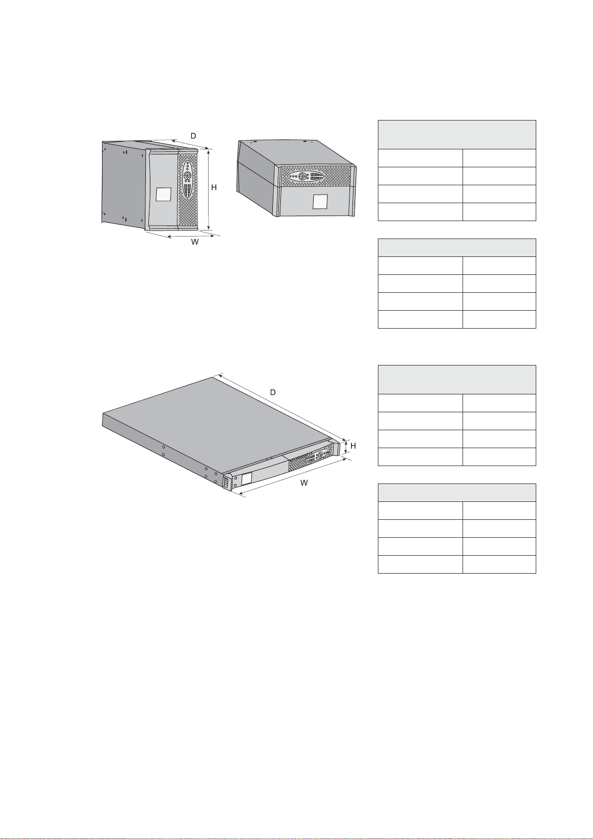
1.1 Standard positions
Tower models
Dimensions (H x W x D)
in mm
Evolution 650 234 x 147 x 418
Evolution 850 234 x 147 x 418
Evolution 1150 234 x 147 x 418
Evolution 1550 234 x 147 x 492
Weights in kg
Evolution 650 8.4
Evolution 850 10.8
Evolution 1150 12.5
Evolution 1550 16.5
Rack models
Dimensions (H x W x D)
in mm
Evolution 650 Rack 43.5 x 438 x 366
Evolution 850 Rack 43.5 x 438 x 512
Evolution 1150 Rack 43.5 x 438 x 512
Evolution 1550 Rack 43.5 x 438 x 556
Weights in kg
Evolution 650 Rack 10.1
Evolution 850 Rack 16.1
Evolution 1150 Rack 16.6
Evolution 1550 Rack 20
34008235EN/AC - Page 6
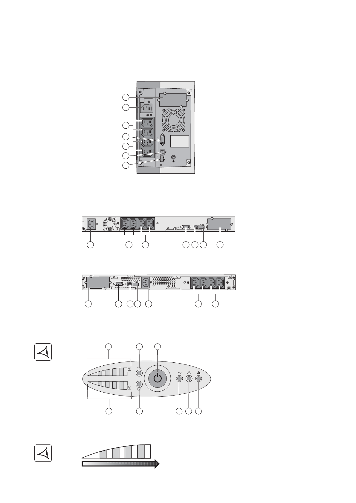
1.2 Rear panels
230V/10A Max
RS232
ROO RPO
1
2
Ue/In/Eing
Us/Out/Ausg
I max 6.5A
2
3
5
1
4
6
7
2
4 6 7
1
3 5
2
4 6 7
1
3 5
Evolution 650/850/1150 Rack
Evolution 1550 Rack
2
1
2
9
10
12
13
14
15
11
8
25
50 75 100
%min max
Evolution 650/850/1150/1550
Evolution 650/850/1150/1550 Rack
1. Presentation
(1) Slot for optional communication card
(2) Socket for connection to AC-power
source
(3) 2 outlets for connection of equipment
(4) RS232 communication port
(5) 2 programmable outlets (1 and 2) for
connection of equipment
(6) USB communication port
(7) Connector for remote ON/OFF and RPO
(Remote Power Off) control
1.3 Control panel
Bargraphs (8) and (11)
(8) Bargraph indicating the percent load
(9) Programmable outlet 1 is supplied
(10) ON/OFF button for UPS and outlets
(11) Bargraph indicating battery-charge
level
(12) Programmable outlet 2 is supplied
(13) Load protected LED
(14) Downgraded operation LED
(15) Load not protected LED
34008235EN/AC - Page 7
 Loading...