

Page 1
Technical Data
Technical Data
Effective November 5, 2014
OAWC-DT – Dual Technology
Wall/Corner Sensor
Catalog# Prepared by
Project Date
Comments Type
Overview
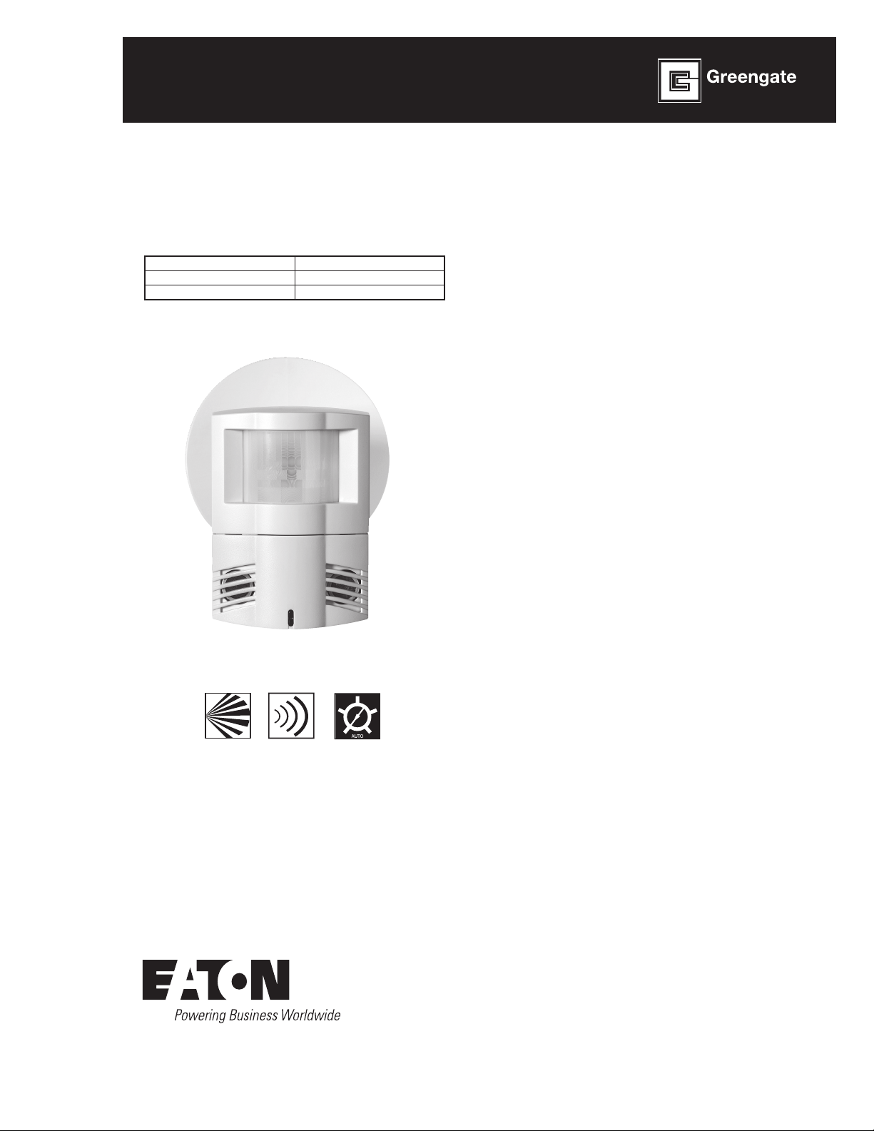
The Dual Technology sensor’s combination of Ultrasonic and Passive
Infrared technologies offers the most complete sensing equipment
available today. Self-adjusting Dual Technology sensors drastically
simplify and reduce a contractor’s installation and adjustment time
period.
Features
MicroSet self-adjusting time delay and sensitivity
Optional built-in light level sensor
Optional BAS/HVAC isolated relay
NEMA WD7 Guide robotic method utilized to verify coverage
patterns
Manual On feature for use with 1 or 2 momentary switches
controlling 1 or more Switchpacks
Selectable Walk-Through Mode
PIR
Activated
Ultraasonic
Activated
Self-Adjusting
Page 2

Technical Data
November 2014
OAWC-DT – Dual Technology Wall/Corner Sensor
Specifications
Technology Passive Infrared (PIR) and Ultrasonic (US)
Power
Requirements
Time Delays Self-Adjusting, 15 seconds/test, 5, 10, 15,
Light Level
Sensing
(-R Models)
Operating
Environment
Housing Durable, injection molded housing. Polycarbonate
Size 4.4”H x 3.4”W x 2”D (112mm x 86.4mm x
Mounting Mounts directly to ceiling tile, to a 4” square box
LED Indicators Red LED for PIR detection; Green LED for
Standards FCC Compliant
Input
0-30 VDC from Greengate Switchpack or Greengate
System
Maximum current needed is 25 mA per sensor
Output
Open collector output to switch up to ten
Greengate Switchpacks
Isolated Form C Relay in (-R models)
Isolated Form C Relay Ratings: 1A 30 VDC/VAC
30 minutes
0 to 300 foot-candles
Temperature: 32°F - 104°F (0°C - 40°C)
Relative humidity: 20% to 90% Non-condensing
For indoor use only
resin complies with UL 94V-0
50.8mm)
and round mud ring or to 4” octagon box
Ultrasonic detection
cULus Listed
RoHS Compliant
Description/Operation
The OAWC-DT combines Ultrasonic (US) and Passive Infrared (PIR)
sensor technologies to monitor a room for occupancy to deliver
maximum energy savings and ensure the greatest sensitivity
and coverage for tough application without the threat of false
triggers. PIR is used to turn the lights ON and then either or both
technologies are used to keep the lights ON. The sensor includes
MicroSet self-adaptive technology that continuously self-adjusts
sensitivity and time delay in real-time, maximizing the potential
energy savings that are available in particular application. In
Automatic On Mode, the lights turn ON when a person enters the
room. In Manual-On Mode, the lights are turned ON by activating
a momentary switch (model # GMDS-*) that is connected to the
sensor. When used with 2 level lighting (-R model only), Bi-level
Automatic On can be achieved which allows Zone 1 to come on
automatically upon occupancy. Zone 2 does not come on unless the
occupant presses the optional momentary switch. When enabled,
the daylighting feature (-R models only) prevents lights from turning
ON when the room is adequately illuminated by natural light.
Applications
Classrooms
Conference Rooms
Large Offices
Common Areas
Computer Rooms
Break Rooms
2
www.coopercontrol.com
Page 3
OAWC-DT – Dual Technology Wall/Corner Sensor
PURPLE (NORMALLY CLOSED)
GRAY (ISOLATED RELAY COMMON)
ORANGE (NORMALLY OPEN)
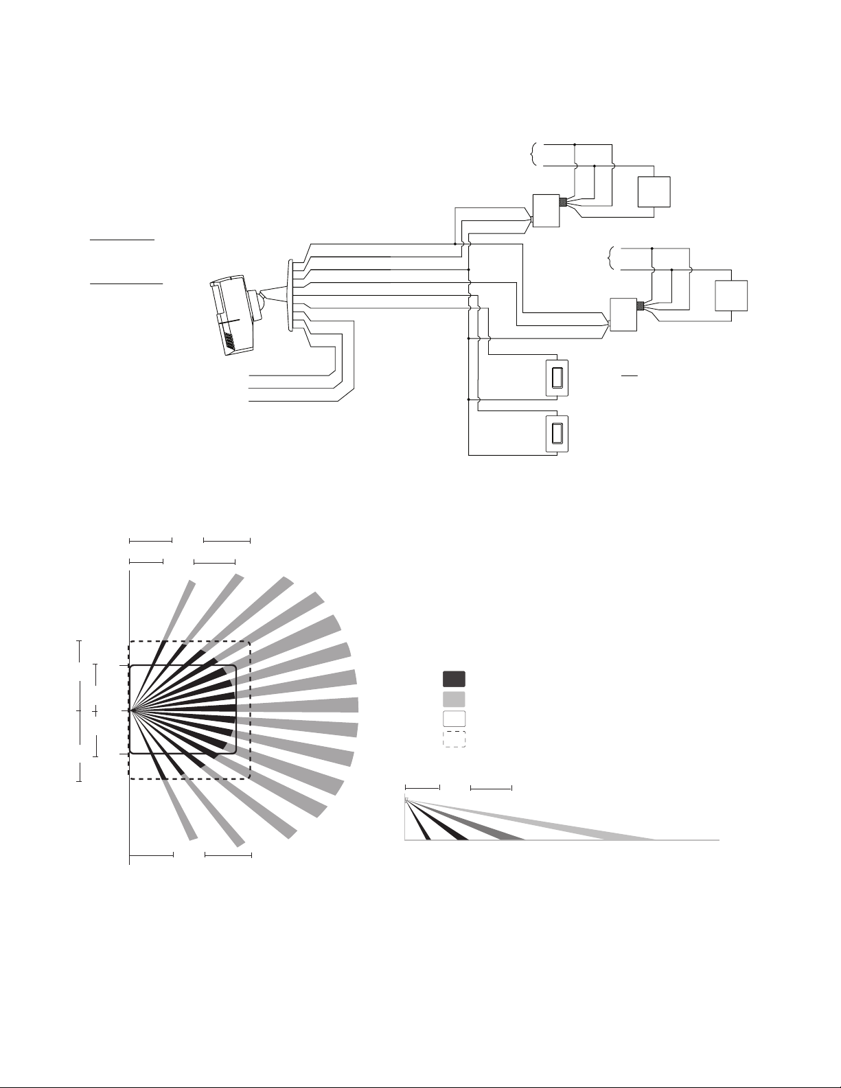
MANUAL MODE OPERATION:
1. SWITCHES ARE REQUIRED TO TURN
CORRESPONDING LOADS ON.
2. LOADS TURN OFF WHEN SENSOR
TIMES OUT OR WITH SWITCHES.
AUTOMATIC MODE OPERATION:
1. WHEN SENSOR ACTIVATES, BOTH
LOADS TURN ON.
2. SWITCHES CAN BE USED TO TURN
LIGHTS ON OR OFF.
3. IF DAYLIGHT SENSOR IS ENABLED AND
LIGHT LEVEL IS ABOVE SETPOINT,
SWITCHPACK CONNECTED TO YELLOW
LEAD WILL NOT TURN LOAD ON.
RECOMMENDED WIRE:
18-3 AWG STRANDED WIRE SHIELDED OR
NON/SHIELDED
LOAD "A"
BLUE
NEUTRAL
HOT
**USE BLACK LEAD FOR 120 VAC.
USE ORANGE LEAD FOR 277 VAC.
CAP UNUSED LEAD.
LINE
**HOT
WHITE
BLUE
SWITCH-
PACK
LOAD "B"
BLUE
NEUTRAL
HOT
**USE BLACK LEAD FOR 120 VAC.
USE ORANGE LEAD FOR 277 VAC.
CAP UNUSED LEAD.
LINE
**HOT
WHITE
BLUE
SWITCH-
PACK
BLACK (COMMON)
BLUE (CONTROL)
RED (15 VDC)
MODEL GMDS - LOAD "B"
(NORMALLY OPEN
MOMENTARY SWITCH)
MODEL GMDS - LOAD "A"
(NORMALLY OPEN
MOMENTARY SWITCH)
BLACK (COMMON)
BLUE (CONTROL)
RED (15 VDC)
NOTES
1. LOADS MAY BE ON SAME
CIRCUIT OR DIFFERENT
CIRCUITS OR VOLTAGES.
2. SP20-MV SWITCHPACK SHOWN.
120/277 VAC 20AMP RATING.
BLACK (COMMON)
YELLOW (CONTROL-OCC/DAY)
BLUE (CONTROL-OCC)
RED (10-30 VDC)
BROWN/WHITE (YELLOW CONTROL)
BROWN (BLUE CONTROL)
Minor Motion, Ultrasonic
Major Motion, Ultrasonic
Maximum coverage area may
vary somewhat according to room
shape and the presence of obstacles.
32’
(9.8 m)
Minor Motion, IR
Major Motion, IR
24’
(7.3 m)
11’
(3.4 m)
11’
(3.4 m)
32’
(9.8 m)
24’
(7.3 m)
0
10 ft
(3 m)
16’
(4.9 m)
16’
(4.9 m)
6 ft
(1.7 m)
15 ft
(4.6 m)
24 ft
(7.3 m)
50 ft
(15.3 m)
Wiring Diagrams
OAWC-DT-120W-R Model
*Wiring diagram for single sensor application.
Visit our website for other wiring diagrams.
Technical Data
November 2014
Coverage
www.coopercontrol.com
3
Page 4
Technical Data OAWC-DT – Dual Technology Wall/Corner Sensor
Activation
3 4
PIR 5
1
9715-000004-00
Power Pack One
Power Pack Two
(-R model only)
(-R model only)
12345678 910
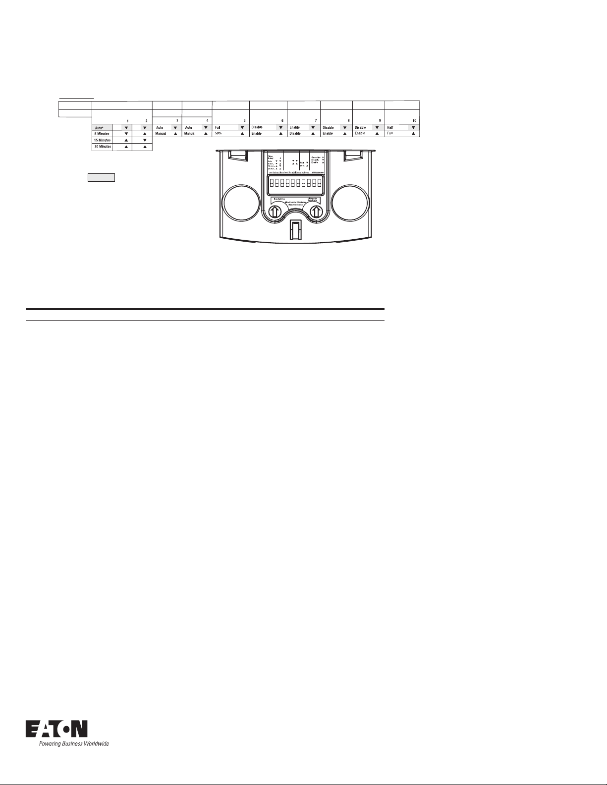
DIP Switch Legend
Time DelayActivation
PIR Sensitivity LEDs OverrideLighting Sweep Daylighting Mode
DIP Switch
Walk-Through Mode
Default =
Activation
*Self-Adjusts to
10 min. user
mode
Controls
Ordering
Catalog # Coverage Field of View Features
OAWC -DT-120W-R 1,200 sq. ft. Wide Angle, 120° w/ BAS Relay and Daylight Sensor
OAWC-DT-120W 1,200 sq. ft. Wide Angle, 120°
Eaton
1000 Eaton Boulevard
Cleveland, OH 44122
United States
Eaton.com
Eaton’s Cooper Controls Business
203 Cooper Circle
Peachtree City, GA 30269
coopercontrol.com
© 2014 Eaton
All Rights Reserved
Printed in USA
Publication No. ACC141015
November 5, 2014
Eaton is a registered trademark.
All other trademarks are property
of their respective owners.
 Loading...