

Page 1
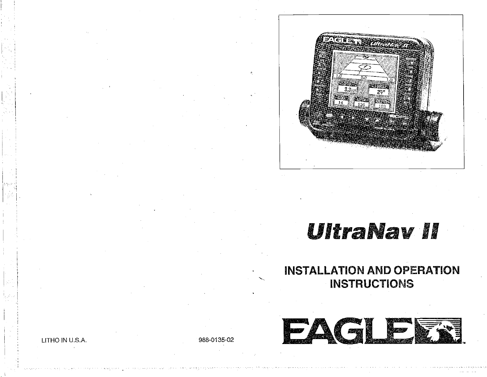
UltraNav
INSTALLATION AND OPERATION
INSTRUCTIONS
II
LITHO IN U.S.A.
PDF compression, OCR, web-optimization with CVISION's PdfCompressor
988-0135-02
E&GI
Ek1
Page 2
USE THIS GPS
CAREFUL
RECEIVER ONLY
NAVIGATOR
OBTAIN POSITION
This OPS
shortest, most direct
waypoint regardless
not
only
a
waypoint,
the
waypoint
As of
GPS
Satellites can
operators.
accurate as the
receiver,
take
advantage
but will also
is
always
this
writing,
navigation system
the
beturned off
Remember that the
system
WARNING!
NEVER RELIES
INFORMATION.
CAUTION
all
(like
path
of
GPS
to a
waypoint.
obstructions.
navigation
of all available
visually
available.
checkto
NOTICE!
UltraNav
using.
of
Defense
Department
operational.
oracburacycan
it's
AS AN AID TO
ON ONLY ONE
equipment)
It
provides
(DOD)
system
be
degraded
or
any
the
tools when
is still in a
GPS
Therefore,
navigation
make certain a
The
II,
NAVIGATION. A
METHOD TO
will show
navigation
prudent
data to the
navigator
travelling
safe
clear,
has not
declared the
testing phase.
atwill
bythe system
receiver is
path
only
the
will
to
to
as
SONAR SPECIFICATIONS
UltraNav II Dimensions
Input Voltage
Current
Transmitter
Frequency
Output
Display
Pixels
Size
UltraNav II GPS
Power 600 watts
(typical)
RECEIVER SPECIFICATIONS
GPS Module Dimensions
Channels
5.875"H x 7.75W x
10-15 vDC
500 ma
650 ma
192kHz
75 wafts
2.8"H x 3.5W
(lights
(lights on)
(RMS)
128Hx160W
20,480
2.5"H x4.1"Wx7" D
Five Parallel
Four
Total
continuous for
All satellites in
Update
Accuracy
Position 25
Velocity
NMEA 0183
RMB
RMC Minimum Recommended
GLL
APB
DBT
MTW Water
VHW
VLW
rate One second
Maximum
Standard
0.25
meters/sec AMS
Without SA PDOP.c6.0
SENTENCES
Minimum Recommended
Present Position
Autopilot Steering
Water
Depth
Temperature
Speed Through
Distance Travelled/LOG
-
Latitude/Longitude,
Data
Water
Sentence,
Sentence,
(oC)
(KPH)
(NM)
3.875"D
off)
(peak-to-peak)
position
view tracked
accuracy
Positioning
meters CEP
achievable with
Service
Part B
Part C
All
1993
rights
Electronics
Eagle
reserved.
subject
manual are simulated.
to
change
without notice.
79
All features and
All
screens in this
Copyright0
specifications
PDF compression, OCR, web-optimization with CVISION's PdfCompressor
Page 3
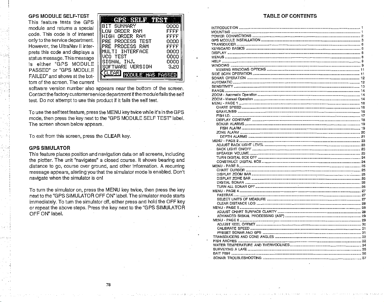
OPS MODULE SELF-TEST
P
feature tests the GPS
This
module and returns
This Code Is of
Code.
to the service
only
However,
prets
status
the UltraNav II inter-
this code and
message.
a
special
interest
department.
displays
This
message
a
is either "GPS MODULE
PASSED" or "OPS MODULE
FAILED" and shows at the bot-
.fl SELl. TESTI .:fl
BIT SUMMARY
LOW ORDER
HIGH ORDER RAM rrrr
PRE PROCESS TEST
PRE PROCESS
MULTI INTERFACE 0000
UCO TEST 0000
SIGNfL INJ.
OFTWARE
CLEAR
.c
VERSION
I
MUE'ULE.:. HASi FA%E
tom of the screen. The current
software version number also
appears
Contactthefactotycustomerservice departmentif
Do not
test.
To use the
mode,
screen shown below
The
To exit from
then
attempt
self test
press
this
to use
this
feature, press
the
next to the "GPS MODULE SELF TEST" label.
key
appears.
screen,
press
product
the MENU
the CLEAR
near the bottom of the screen.
fails
if it
keytwice
key.
OPS SIMULATOR
feature
This
the
plotter.
distance
place.s position
The unit
to
course over
go,
message appears,
navigate
To turn
next to the
immediately.
or
when the simulator is onl
the simulator
"GPS SIMULATOR
To turn the simulator
repeat
the above
alerting
steps.
and
s:navigatesJ
ground,
that the simulator mode is enabled. Don't
you
on,
press
OFF ON" label.
Press the
navigation
data on all
a closed course. It shows
other information. A
and
the MENU
off,
either
key
key
The simulator mode starts
press
next to
OFF ON" label.
RAM
FEET
0000
0000
RAM
FETE
0000
3.20
the modulefailstheselt
self test.
the
while it's in the
GPS
screens, including
bearing
recurring
then
twice,
and hold the
press
the
OFF
the "GPS SIMULATOR
and
key
key
TABLE OF CONTENTS
INTRODUCTION
MOUNTING 1
CONNECTIONS 2
POWER
GPS MODULE INSTALLATION 3
TRANSDUCER
KEYBOARD
DISPLAY 8
MENUS 8
HELP
WINDOWS 9
VIEWING
SIDE SCAN OPERATION ii
SONAR
AUTOMATIC 12
SENSITIVITY is
RANGE ¶4
ZOOM - Automatic
ZOOM - Manual
MENU-PAGE
CHART SPEED is
GRAYUNE® 16
FISH I.D 17
DISPLAY CONTRAST 18
SONAR
ZONE
MENU-PAGE2 23
ADJUST BACK LIGHT
BACK LIGHT ON/OFF 23
SPEAKER VOLUME 23
TURN
CONSTRUCT DIGITAL BOX 24
MENU-PAGE3 25
CHART
DISPLAY ZOOM BAR 25
DISPLAY ZONE BAR 26
DIGITAL SONAR 26
TURN ALL SONAR OFF 26
MENU-PAGE4 27
FASTRAK 27
SELECT UNITS OF MEASURE
CLEAR DISTANCE LOG• 28
MENU-PAGES 28
ADJUST CHART SURFACE CLARITY 28
ADVANCED SIGNAL PROCESSING
MENU-PAGES 29
ADJUST KEEL OFFSET 30
CALIBRATE SPEED 31
PRESET SONAR AND GPS 31
TRANSDUCERS AND CONE ANGLES 32
FISH ARCHES 32
WATER TEMPERATURE
SURVEYING A LAKE 35
BAIT FISH 36
SONAR TROUBLESHOOTING 37
BASICS 6
WINDOWS OPTIONS
OPERATION 12
Operation
Operation
I 16
ALARMS . 19
FISH ALARM ¶9
ALARM 20
DEPTH ALARMS 21
LEVEL
BOX OFF 24
DIGITAL
CURSOR
(ASP)
AND THERMDCLINES
6
9
11
14
14
23
25
27
29
34
78
PDF compression, OCR, web-optimization with CVISION's PdfCompressor
Page 4
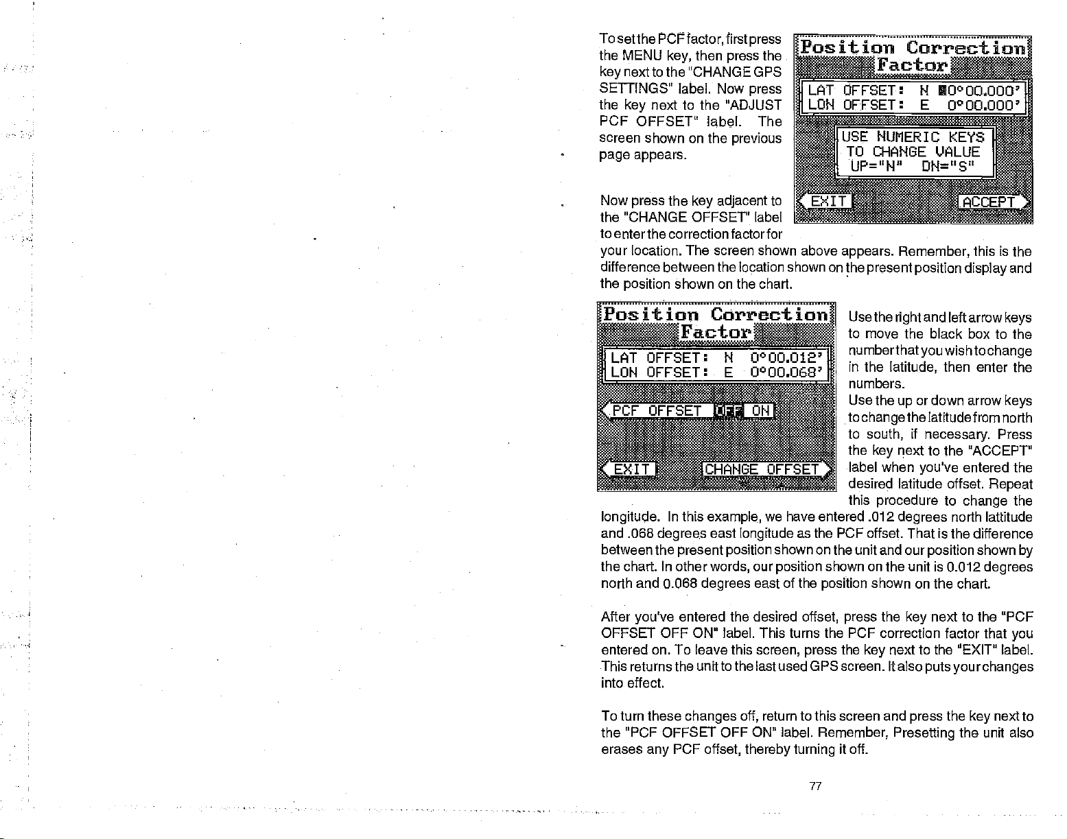
To
setthe
PCFfactor,
the MENU
next to the "CHANGE GPS
key
SETTINGS" label. Now
the
PCF
screen shown on the
page appears.
key,
next to the "ADJUST
key
OFFSET'
then
label.
first
press
previous
press
the
press
The
jgJt
ion
Correction
9r
UOOOaOOO
0OO,OOO'
IUSE
NUMERIC
TO CHANGE VALUE
I
UP="H" DN="S"
KEYS
I
l
Now
the "CHANGE OFFSET" label
to eriterthe correctionfactorfor
your
difference between the location shown on the
the
position
Position Correction
Lc4T OFFSET:
LON OFFSET:
longitude.
and .068
between the
the chart. In other
north and 0.068
press
the
key adjacent
to
SEPT
location. The screen shown above
shown on the chart.
Factor
N O0OOO12
E U°OO.068'
In this
example,
degrees
east
present position
words,
degrees
we have entered .012
longitude
our
east of the
as the PCF offset. That is the difference
shown on the unit and our
position
shown on the unit is 0.012
position
appears. Remember,
Use the
to move the
numberthatyou
in the
numbers.
Use the
to
to
the
label when
desired latitude offset.
this
present position
and left arrow
right
black box to the
wishto
latitude,
up
changethe
south,
next to the "ACCEPT"
key
procedure
degrees
shown on the chart.
then enter the
or down arrow
latitudefrom north
if
necessary.
you've
entered the
to
change
north lattitude
position
this is
display
change
Press
Repeat
shown
degrees
the
and
keys
keys
the
by
After
you've
OFFSET
entered on. To leave this
This returnsthe unitto the last used GPS screen. Italso
into effect.
To turn these
the "PCF OFFSET OFF ON" label.
erases
entered the desired
OFF ON" label. This
any
changes
PCF
offset,
off,
thereby turning
offset, press
the PCF
turns
screen,
press
return to this screen and
Remember,
77
the
correction factor that
the
key
it off.
next to the "PCF
key
you
next to the "EXIT" label.
putsyourchanges
the
press
Presetting
next to
key
the unit also
PDF compression, OCR, web-optimization with CVISION's PdfCompressor
Page 5
OFFSET
PCF
GPS
The
to determine
factor is the Earths
in the calculations
matters more
navigation system
position
your
shape.
have
complex,
what the deviations are. The size and
to
approximate
if
errors
your navigation
a different one.
the earth's surface are
The term used for these
To reduce the errorfactor between
to move or "offset" the
relies on
based on satellite data and other factors. One
Since
be made to accommodate deviations. To
to
not
everyone
device uses one
position
complex
Earth is not atrue
the
uses
shape
improved
ellipsoids
datum,
shown on the
the chart. The unit will add this offset to all
Remember,
never
feature
is. This feature should
chart.
the GPS error is
be used in an
should
only
be used if
attempt
always
very dynamic
to cancel the error. In
your map
be reset to zero
indicates what the
mathematical calculations
sphere,
the same data to
of the
ellipsoids
often. This can
ellipsoid,
while
variations
determine
that are used
chart uses
your
is "Datum."
this unit
gives you
display
position displays
the
capability
to match the one
at all times.
and the PCF offset should
general
when finished with that
(0)
terms this
possible
make
lead to
on
error
INTRODUCTION
The UltraNav II is a
differntial
its class.
also one
"UltravisionTM"
of the easiest-to-use
and detail. The
Installing
speed,
surface
Read this manual
It makes a
MOUNTING
Install the UltraNav
clearance behind the
in the bracket base
need to
secure the
place a piece
OPS receiver
ready
menu features and
Using
screen shows the underwater world with
display
an
optional
water
and take itwith
reference if
great
allow wood screw
mounting
the unit to attach the
high quality,
and
keyboard
ST-T
speed/temperature
temperature,
II in
any
wide screen combination sonar and
with
performance
"soft-key" operation,
products
you
that
are also
and distance travelled
the firstfew times
you
it.
need
convenient
that is
has ever built. The wide
Eagle
lighted
sensor,
location,
unitwhen it is tilted forthe best
orthrough-bolt mounting.
of
plywood
hardware. Make certain there is
power
on the back of thin
and transducer cables.
second
to
none in
the UltraNav II is
resolution
high
for
night operation.
gives digital
(log) displays.
use
you
provided
viewing angle.
fiberglass panels
enough
your
there is
Holes
You
room behind
boat
unit.
may
to
For
example, suppose you
are
stopped
marked on a chart. Your unit shows a
degrees
Factor
Position
less than the one on the chart.
(PCF)
Offset
feature,
you
make the
Correctq
Factor
OFFSET:
LAT
LOll OFFSET:
N.:,C!PiJO1I1OC.
76
at a location
longitude
Using
that is
position
accurately
that is .010
the Position Correction
unit read the same as the chart.
If
move,
you
tinuously
position displays.
more
closely
used
by
son,you
entering
offset is saved
doesn't
turned
erase the PCF factor.
does
the unit will con-
add the
change
to all
This makes it
match the datum
the chart. Forthis rea-
should be careful when
the PCF offset. This
in
memory.
change
off.
whenthe unit is
However,
a Preset
The smallest hole that
Afterthe hole is
then
first,
It
pass
After the cables
compound.
through
transducer cable.
Offset
the slot and
will
drilled, passthe
the
power
have been
the bracket to cover the hole. Route the
break out one of the other slots in the bracket for the
one
pass
cable down
routed,
power
transducerconnector
through
fill the hole with a
1
or transducer
up throughthe
it.
SLOT
good
is one inch.
plug
marine
power
hole
sealing
cable
PDF compression, OCR, web-optimization with CVISION's PdfCompressor
Page 6
POWER
The UltraNav
results,
power
problems
attach the
#18
CONNECTIONS
I! works
attach the
cable to an
with electrical
powercable
wire
gauge
onto it. The
and white. Red is
certain to
source as
the
battery
in the event of
attach the in-line
possible.
or
or
power
battery
power buss,
buss.
a short.
polarity protection
connected
backwards,
from a
power cable
accessory
interference.
twelve-volt
directly
or
power
direotlytothe battery.
cable has
power
the
positive
lead,
fuse holder to the
For
example,
This will
attach one
if
protect
The UltraNav
built into
no
damage
the UltraNav II.
battery system.
to the
battery.
however
buss,
Therefore,
ifs saferto
If
the cable
four
black is
you
end of the fuse
II uses a
negative
red lead as
have to extend the
both the unit and
3-amp
If the
will occur to
the unit.
For the
You can
istoo
wires; red, black,
you
go
or
ground.
attach the
may
ahead and
short,
close to the
power
holder
directly
the
power
fuse. There is
power
wires are
best
have
splice
green,
Make
power
cable to
to the
cable
reverse
The
plotter display
Overboard mode. Your
is
pressed
"0" Steer
Man
shown
to the
Overboard
The UltraNav II
table.
However,
The UltraNav II
Man Overboard screen
the
stop
next to the
navigtion.
unitfrom
"DISABLE MOB" label.
automatically
the "S' with a circle
by
waypoint flag
was
key
doesn't save the Man Overboard
it does save
always
shows
navigating
shows a .1
when
position
to
get
pressed.
IMPORTANT!
the
position
navigation
whenever the Man
to the Man
the Marl
and
back to the
on the Man
datato
Overboard
This resets the Man
mile
Overboard
the
by
waypoint
position
position
the
position
Overboard
position, press
in
display
the Man
key
icon with a
saved when the
in the
waypoint
Overboard
shown
is
key
pressed.
Overboard
was
screen.
on the
To
the
key
Do not use
Failure to use
If
you're
temperature
the
sensor's cable to
this
product
a
installing
sensor's
3-amp
connector marked
TOP"
ON
TO
S PEE P1
TEMP
SENSOR
IMPORTANT!
without a
fuse will void
an
optional
installation
the UltraNav
"SPEED/TEMP CABLE'
CONNECTOR
ULTRANAV II
3-amp
your
speed/temperature sensor,
manual for
Il's
fuse wired into the
warranty.
mounting
power
instructions.
cable and
power
read the
it
plug
cable!
speed/
Route
into the
For
example, suppose you
the Man Overboard
then
displays
then switches
key again,
first
you
Repeated
your present
Overboard
must first clear the old Dosition by
stores
backtothe Position screen. If
it will
still show
pressed
pressing
the Man Overboard
position!
is
key
pressed.
are
then
key,
your
present position
navigation
of the Man
The unit
To save a
viewing
press
Overboard
onlysaves
"DISABL MOB" label.
You can
however
stops
Remember,
the
tion are also
safety
procedures
navigate
when
navigating
saving
person immediately
good
courses. Instruct all
before
to do before
For more information on
a
Waypoint"
to a
you go
to the recalled
the victim is the
accident
leaving
any
emergency
section in
waypoint using
back to the Man Overboard
waypomnt.
primary goal.
after the accident
preventatives.
members on board
the dock. Make certain all on board
occurs.
and
saving
recalling waypoints,
this manual.
the Position
the OPS
on the
you press
data to the
key
key
the
new Man Overboard
pressing the
the
happens.
The
screen,
The
key.
Man Overboard
the Man
position you
-
not
your present position.
does not
position
thefirsttime the
key adiacent to the
Waypoint
screen,
all
Try
Training
Coast Guard has
your
and
you press
UltraNav II
were in when
repeatedly
Dostion.
Recall
first
screen,
Overboard
save
Man
you
feature,
the UltraNavIl
options
to rescue
and educa-
excellent
boat on
safety
know what
see "How to Save
2
75
PDF compression, OCR, web-optimization with CVISION's PdfCompressor
Page 7
PRESET
The Presetfeature returns all sonar and OPS units to their
settings.
mode onthe
waypoints
To
appears.
the UltraNav
to their
MAN OVERBOARD
One of
fall overboard. This situation can be
salt. It's
course,
measures
can
This resets the units of
sonarside,
or
routes,
the
preset
Press the
II returns to
factory settings.
boating's mostterrifying
particularly dangerous
the first
to
try
use the UltraNav II to
however.
unit,
press
key
thing
and rescuethe
displaycontrast,
the
nextto that label. The menu screen
the OPS
to do is remain calm and
help
measure,
and more. This doesn'terase
MENU
key
position
events is
deadly
at
person.
start a search
night
or if
If
speaker
until the "PRESET UNIT"
screen.
having
on
you're
lose
you
pattern.
volume, automatic
All units will be
afriend
any body
orfamily
of
out of
all standard
try
of the
sight
iasmffg
H 36°09.669'
Once
you're
after initial rescue efforts have
failed, press
MAN OVERBOARD
screen shown at
Your
position
the
top
pressed
navigation
Course
display. Using
of the
overboard
back at
the UltraNav Vs
at the time
left corner of the
the Man Overboard
data
(COG),
display gives you
position.
the helm
The
key.
right appears.
you pressed
display.
displays
and TimeTo Go
these
showing
displays
the information
UI
9E°37.171'fIsnBLE
isiia[
4:26:35
Pfl
..L
DTI3 0.07
BRG 3340
bbs
TTG00:O2:4O
Beneath
At the
key.
the Distance
(TTG)
with the
along
74
3400
the Man Overboard
the
position
bottom of the screen are the
backto the
plotterinthe
need to steer
you
FHJ
[H]
is the time that
(DTG), Bearing (BRG),
postion
original factory
any
label
disappears
water,
sight
person, you
.
key
atthe
lower
back to the man
and
returned
member
fresh or
of land. Of
safety
MOBS
S0.11I
is shown in
you
of the
top
corner
right
E
The white wire
another electronic
wire is for a differential
wires are not
green
To connect
a two-wire
white and black
to the black
other device. See
tions. Use the
the
green
Note: The
to use
environments.
shielded wires
two instruments.
manual for more information.
The GPS thodule can be installed on a flat surface or
view of the
from the
it due to the
GPS MODULE INSTALLATION
adapter)
cabin
roof,
the
pole mounting adapter
stall the module on a one inch mast.
However,
antenna shouln't be the
is for a NMEA interface. The UltraNav II sends data to
GPS
power
devices
(DGPS)
through
ends
their
cable. Do not connect the shield to the
navigation
used, tape
a device to the UltraNav's NMEA
shielded cable from the other device's NMEA
wires on the UltraNav il's
wire on the
the other instrument's manual
same
procedure
and black wires on the
shielded wire is not
high
To avoid
whenever
See the NMEA section in the GPS
on a
sky
satellites,
Mount the module in an area that
pole.
at all times. In order for the module to receive the
it must not be obstructed. An ideal
or deck. The
for
lightning protection,
to connect the DGPS
UltraNav
absolutely necessary,
electrical noise levels found in
problems
making
gunnels
highest part
later,
a communications connection between
also make a
lets
you
in-
the
of
the white wire. The
receiver
input.
so that
power
they
output (white wire);
cable.
for more
II.
we
highly suggest
good
17mm
(11/16')
Hole
the boat.
-
Surface
If
mounting
plied
plate.
and one 17
module's cable.
module and
hole in
surface.
ers,
GPS module
Mounting
have
you
surface,
with the GPS
Drill four 5.5 mm
mm
pass
the
gasket
Use 5 mm
and
lock
to the
With Access
access underneath the
use the
(11/16")
Attach the cable to the
it
washers to fasten the
mounting
gasket sup-
module as a tem-
(7/32a)
down
and
th mounting
screws,
holes
hole for the
through
the
flat wash-
surface. Route the cable to the UltraNav II.
3
GASKET
DECK
/
green
If the white
cannot short.
intput
Solderthe shield
wiring
receivers
however it is best
today's
that
section in this
the
(with
guarantees
location
location.
5.5mm
sMMscREws
and
attach
to the
instruc-
output
marine
you
supplied
a clear
signals
is on a
Attaching
(7/32")
Hole
(4 places)
.
use
to
PDF compression, OCR, web-optimization with CVISION's PdfCompressor
Page 8
Surface
If
you
the "cleats"
Mounting
don't have
supplied
can "snake" the
will still need
the
gasket
cable.
cable
through
gasket.
cleats
as
Drill the
the
mounting
UltraNav II.
"CLEAT"
to be drilled in
as a
Attach the cable to
the
Slide
the
templates)
then
holes,
surface
-
Without Access
access to the
with the
module's
UltraNav II.
cableto a
the
template,
mark and drill
the
gasket
"cleats" onto each
and down the
mark four holes for
replace
the cleats
with 5 mm
back side of the
(Note:
location that is
mounting
surface for the
the 17mm
module .and
end of the module
on the module and
(#10)
dropthe
hole. Place the
5 mm
(#10)
screws.
mounting surface,
This is
assuming you
accessable. A hole
cable.) Using
(11/16")
hole for the
use
other end of the
module on the
and
mounting
fasten them
Route the cable to the
(using
screws.
the
to
strength (the higher
the
ber,
to-noise ratio
erthe SNR
also.
better),
(SNR).
number,
the num-
and the
The
the
The lower half of the
shows statistics for
receiver's five channels.
includes the
its
(PRN),
User
(UDRE),
The
an "OK"
68
percent
status
Differential
Time status
UDRE is the
in this
of the time.
each of the
satellite number
(STAT),
Range
(TIME),
range
then the
field,
signal-
high-
better,
screen
This
the
Error
error
range
and if SA
from
your position
errorto that
(Selective
to the
satellite is 8 meters or less
Availablity)
satellite. If there is
is on or off.
DRILL
•
FOUR
PLACES
GA5
CABLE
For mOre
SELECT UNITS
MEASURE
(See
TRUE and
True and
the world.
location our
true
Charts are
north. If
either have to convert
The UltraNav II
information,
OF
the
Select Units of Measure in the
MAGNETIC POSITION
magnetic
north are not
It's where all lines of
compasses point.
at a location in
north,
usually
you ptot
laid out
a
course on chart
can
display navigation
When it's turned on for
the MENU
press
next to the
the "SELECT UNITS
to the "BEARING"
Press the
keywhile
"CHANGE GPS SETTINGS" label.
OF MEASURE' label.
label; This moves the black
next to the "EXIT" label
key
read
according
beacon
your
always
longitude
It lies
Canada.
the
several hundred
to
aMercatorprojectionthatuses true
using
magnetic readings
information in
the first time
magnetic
a GPS screen is
when
receiver's manual.
Plotter section of
same. True north is
converge. Magnetic
the
Mercator
to
true or use true
this
north is the
miles to the south of
projection, you'll
readings.
magnetic
is used. To switch to
displayed.
Nowsimply pressthe key
you're
Next,
press
Now
box from "MAG" to "TRU."
the
press
finished.
key
manual.)
the
top
or
true.
true,
the
key
next to
next
of
4
73
PDF compression, OCR, web-optimization with CVISION's PdfCompressor
Page 9
DGPS
(Differential GPS)
You'll have to tell the UltraNav II which beacon receiver's data to
and
key,
press
previous page appears.
the
setup
then
pressthe key
the
key
parameters
next
The beacon receiver is
frequency
Repeat
page.
shown
and bit rate of the station
the above
Now
below
press
appears.
steps
the
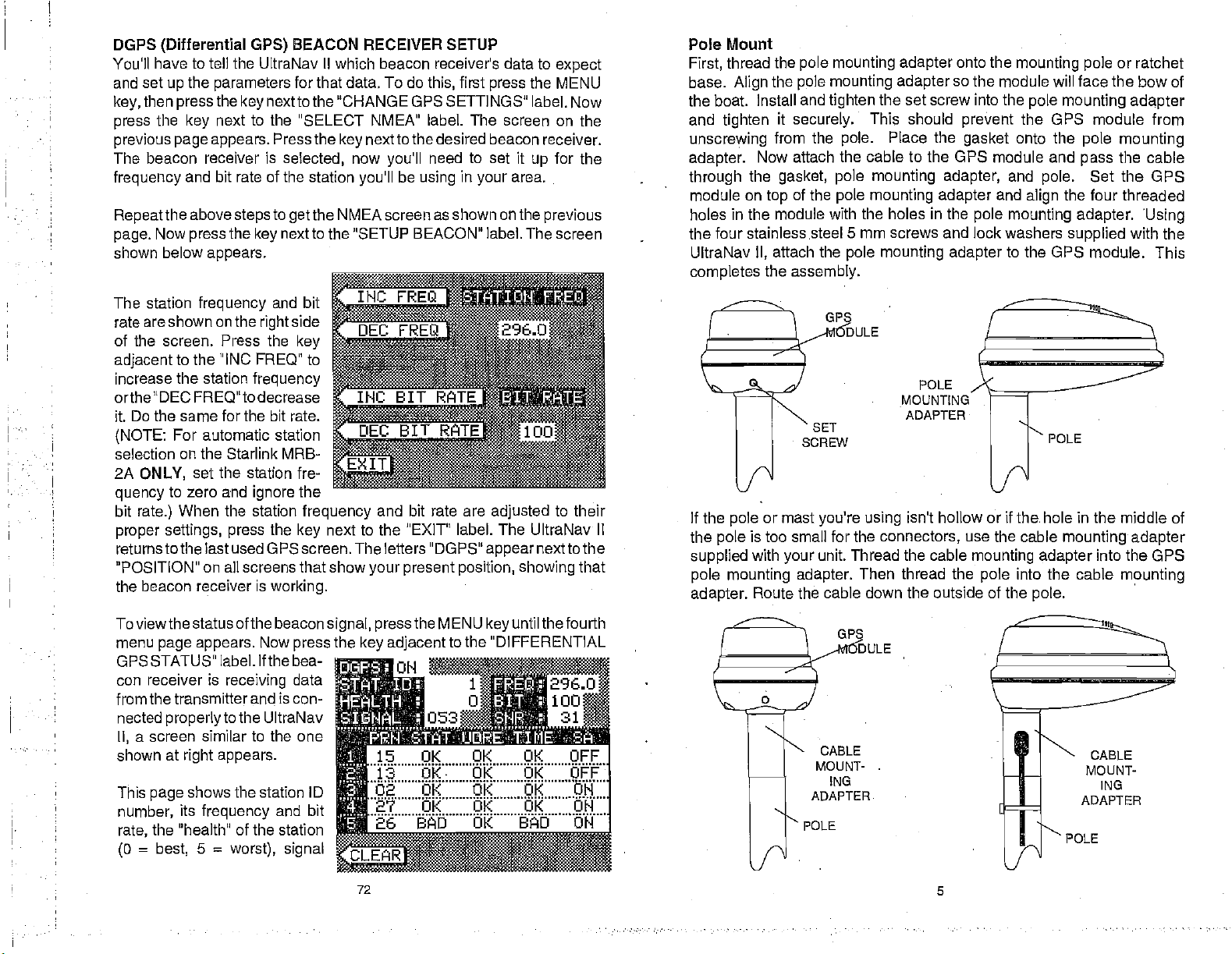
BEACON RECEIVER SETUP
for
that data.
To do
this,
first
press
nextto the 'CHANGE GPS SETTINGS"
to
the "SELECT NMEA" label.
Pressthe
selected,
to
the NMEA screen as shown on the
get
nextto the "SETUP BEACON" label. The
key
nexttothe desired beacon receiver.
key
now
you'll
be
you'll
using
need
The
to
in
set it
your
the MENU
label. Now
screen on the
up
area.
previous
expect
for the
screen
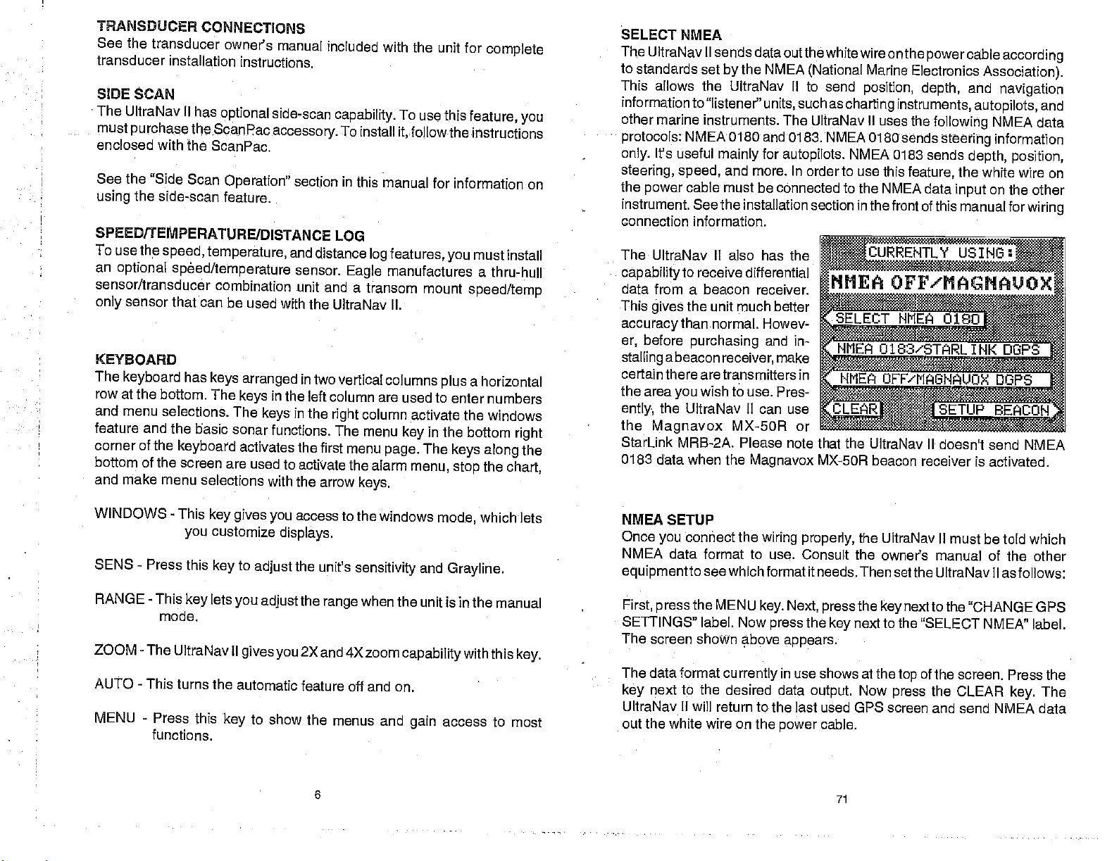
Pole Mount
thread the
First,
base.
Align
pole mounting adapter
the
pole
the boat. Install and
and
tighten
unscrewing
adapter.
through
module on
holes in the module
it
securely.
from the
Now attach the cable to the GPS module and
the
gasket, pole mounting adapter,
of the
top
mounting adapter
tighten
the set screw
This should
pole.
pole mounting adapter
Place the
with the holes in the
onto
the
mounting pole
so the module will face the bow of
into the
prevent
gasket
pole mounting adapter
the GPS module from
onto the
and
pole.
and
align
pole mounting adapter. Using
the four stainless steel 5 mm screws and lock washers
UltraNav
completes
attach the
II,
the
assembly.
pole mounting adapter
to the OPS module.
or ratchet
pole mounting
the cable
pass
Set
the OPS
the four threaded
supplied
with the
This
The station
are shown on the
rate
frequency
of the screen. Press the
adjacent
increase the station
to the INC FREQ" to
and bit
side
right
key
frequency
orthe DEC FREQ"to decrease
it. Do the same for the bit rate.
(NOTE:
selection on the Starlink MRB-
2A
quency
bit
proper settings, press
For automatic station
ONLY,
rate.)
set the station fre-
zero and
to
When the station
ignore
the
the
frequency
next to the "EXIT' label. The UltraNav II
key
and bit rate are
returnstothe last used GPS screen. The letters "DGPS"
"POSITION" on all screens that show
the beacon receiver is
working.
Toviewthe status of thebeacon
menu
page appears.
GPS STATUS" label. If the bea-
con receiver is
from the transmitter
nected
II,
shown at
This
number,
rate,
(0
properly
a screen similar to the one
right appears.
shows the station ID
page
its
frequency
the "health' of the station
=
best,
5
Now
press
and
data
is con-
receiving
to the UltraNav
and bit
=
worst), signal
your present position,
signal, pressthe
the
key adjacent
15
OK OK OK OFF
OK OK OK OFF
02 OK
27 OK OK OK ON
ft
26 BAD OK BD ON
MENU
the "DIFFERENTIAL
to
adjusted
appear
keyuntil
OK OK ON
to their
nexttothe
showing
thefourth
that
SET
SCREW
If the
the
supplied
or mast
pole
is too small for the
pole
with
your
you're using
unit. Thread the cable
pole mounting adapter.
adapter.
Route the cable down the outside of the
CABLE
MOUNT-
ING
ADAPTER
POLE
ULE
POLE
MOUNTING
ADAPTER
isn't hollow or if the. hole in the middle of
connectors,
Then thread the
POLE
use the cable
mounting adapter
pole
mounting adapter
into the cable
pole.
POLE
into the GPS
mounting
CABLE
MOUNT-
ING
ADAPTER
72 5
PDF compression, OCR, web-optimization with CVISION's PdfCompressor
Page 10
TRANSDUCER
See the
transducer
transducer
SIDE
SCAN
The UltraNav
must
purchase
enclosed
See the
using
SPEED/TEMPERATURE/DISTANCE LOG
with the
"Side Scan
the side-scan
To use the
an
optional
sensor/transducer
sensor that can be
only
KEYBOARD
The
keyboard
row at the
and menu
feature and
corner of the
bottom of the screen are
and make menu
CONNECTIONS
owner's manual
installation
II has
instructions.
optional side-scan
theScanpacaccessory.
ScanPac.
Operation"
feature.
speed,
bottom. The
selections. The
temperature,
spOed/temperature
combination unit
used with
has
keys arranged
in the left column
keys
the basic
keyboard
selections with the
keys
sonar functions. The
activates the
used to
included with the
capability.
To install
section
and
sensor.
in this
distance
Eagle
and a transom mount
the UltraNav II.
in two vertical
in the
right
first menu
activate the alarm
arrow
unit for
To use
this
feature, you
it,followtheinstructions
manual for information
features,
log
manufactures a
columns
are used to enter
column activate the
menu
key
page.
keys.
you
speed/temp
a
plus
in the bottom
The
keys along
menu, stop
complete
on
must install
thru-hull
horizontal
numbers
windows
right
the
the
chart,
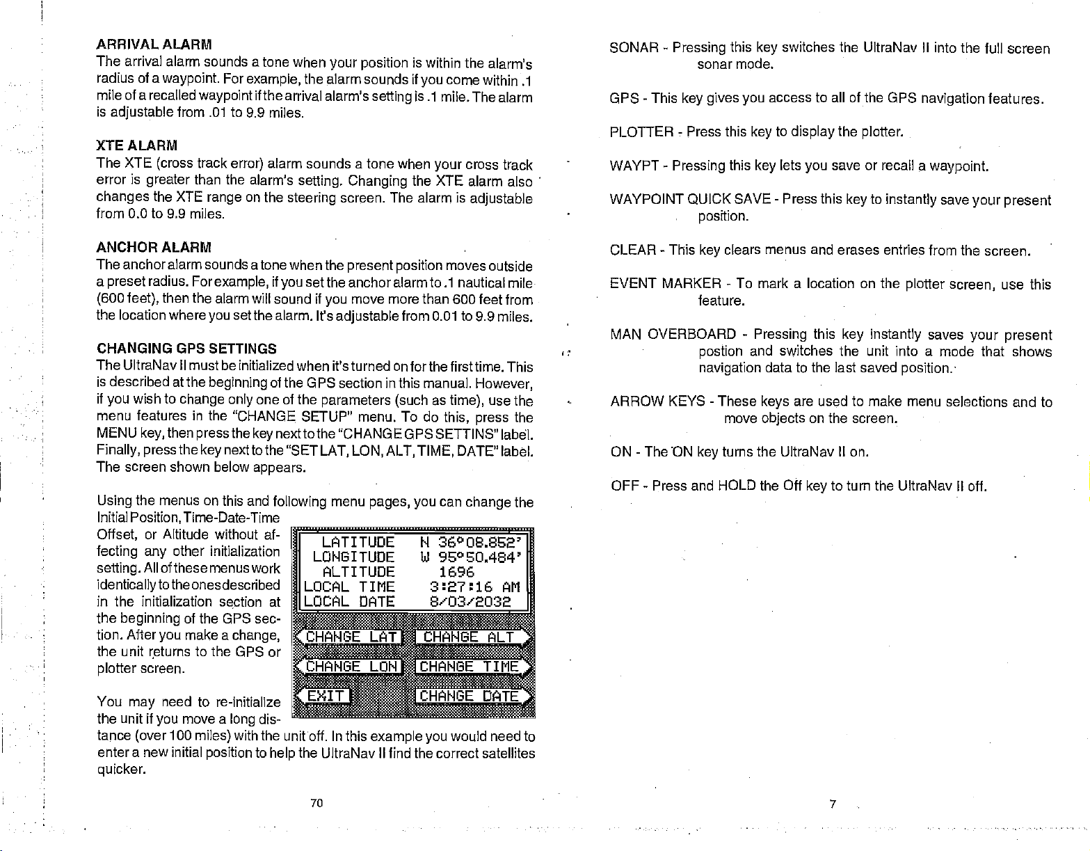
SELECT NMEA
UltraNav II
The
to
standards set
This
allows the UltraNav II to send
information
other
marine instruments. The UltraNav II uses
protocols:
It's useful
only.
steering, speed,
the
power
instrument. See the installation section in the
connection information.
The
UltraNav II also has the
capability
data from a beacon receiver.
This
gives
accuracy
before
er,
stalling
a beacon
sends data outthewhite wire onthe
the NMEA
by
to "listener"
NMEA 0180
mainly
cable
units,
and 0183. NMEA 0180
for
and more. In order to use this
must be connected to the
(National
such as
autopilots.
NTLY
to receive differential
the unit much better
thannormal. Howev-
purchasing
receiver,
and in-
make
NIIEA
Marine
position,
charting instruments,
NMEA 0183
NMEA data
certaintherearetransrnitters in
the area
ently
the
Magnavox
StarLink MRB-2A. Please note that the
0183 data when the
wish to use.
you
Pres-
the UltraNav II can use
MX-50R or
Magnavox
MX-50R
UltraNav II doesn't send NMEA
beacon receiver is activated.
powercableaccording
Electronics
depth,
the
following
sends
sends
feature,
front of this manual for
Association).
and
navigation
autopilots,
NMEA data
steering
information
depth, position,
the white wire on
on the other
input
and
wiring
USING:
OFF'MAGHAUOX
WINDOWS - This
SENS - Press
RANGE - This
mode.
key gives
customize
you
this
key
lets
key
ZOOM - The UltraNav II
AUTO - This turns
MENU - Press
functions.
the automatic
this
key
to
you
gives you
to show
access to the windows
you
displays.
the unit's
adjust
the
adjust
range
2X
and 4X zoom
feature off and on.
the menus and
6
mode,
sensitivity
and
Grayline.
when the unit is in the
capabilitywith
access
gain
whichlets
manual
this
key.
to most
NMEA SETUP
Once
NMEA
equipmentto
First,
SETTINGS" label. Now
The screen shown above
The data format
key
UltraNav II will return to the last used GPS
out the white wire on the
connect the
you
data format to use. Consult
wiring properly,
seewhich format it needs. Then
the MENU
press
key. Next, press
press
currently
appears.
in use
next to the desired data
power
the
the owner's manual of the other
the
the
output.
next to the "SELECT NMEA" label.
key
shows at the
Now
cable.
71
UltraNav II must be told which
setthe UltraNav II as follows:
next to the "CHANGE G
key
of the screen. Press the
top
the CLEAR
press
screen and send NMEA data
key.
PS
The
PDF compression, OCR, web-optimization with CVISION's PdfCompressor
Page 11
ARRIVAL ALARM
The arrival
radius of a
mile of a recalled
is
adjustable
XTE ALARM
The XTE
error is
changes
alarm sounds a tone when
waypoint.
waypoint
from .01 to 9.9
track
(cross
greater
than the
the XTE
range
from 0.0 to 9.9 miles.
For
example,
if the arrival alarm's
miles.
alarm sounds a tone when
error)
alarm's
on the
steering
your position
the
alarm sounds if
setting
setting. Changing
screen. The
is
within the
you
come
alarm's
within .1
is .1 mile.The
cross track
your
the
XTE alarm also
alarm is
adjustable
alarm
SONAR
-
Pressing
this
sonar mode.
GPS - This
key gives you
PLOTTER- Press this
WAYPT
WAYPOINT QUICK
-
Pressing
position.
this
SAVE
switches
key
access to all of the GPS
to
key
display
lets
key
-
Press
the UltraNav II into the full
the
plotter.
save or recall
you
this
key
to
navigation
a
waypoint.
instantly
save
your present
screen
features.
ANCHOR ALARM
The anchor alarm sounds
a
(600 feet),
the location where
CHANGING GPS SETTINGS
preset
radius. For
then the alarm will sound if
you
atone when the
example,
if
you
set the alarm. It's
The UltraNav II must be initialized
is described at the
if
wish to
you
menu features in the
MENU
key,
then
Finally, press
beginning
change only
pressthe
the
next to the "SET
key
The screen shown below
the menus on this and
Using
Initial
Position,
Offset,
fecting any
setting.
identicallytothe
in the initialization
the
beginning
tion. After
the unit returns to
screen.
plotter
Time-Date-Time
or Altitude without af-
other initialization
All of these
you
menus work
ones
described
section at
of the GPS sec-
make a
the GPS or
of the GPS section in this
one of
"CHANGE.
nexttothe "CHANGE GPSSETTINS"
key
appears.
following
change,
moves
present position
set the anchoralarmto .1
move more than 600
you
adjustable
from 0.01 to
outside
nautical mile
feet from
9.9 miles.
when it'sturned on forthefirsttime. This
manual.
the
parameters (such
SETUP" menu. To do
LAT, LON,
menu
pages, you
ALT,
TIME,
as
time),
this,
can
However,
use the
press
DATE"
change
the
label.
label.
the
LATITUDE N 36°OS.852'
LONGITUDE hi 95°EO.464'
ALTITUDE 1696
TIME 3:7:j AM
DATE S'03'2032
GE flNGE ALT
flHANGE
TIME
CLEAR
-
This
clears menus and erases entries from
key
EVENT MARKER - To mark a location on the
feature.
MAN OVERBOARD
postion
navigation
-
ARROW
KEYS
ON - The 'ON
-
OFF
Press and HOLD the Off
These
move
turns the UltraNav II on.
key
-
Pressing
and switches the unit into a
data to the last saved
keys
objects
this
key instantly
are used to make
on the screen.
to turn the
key
the screen.
plotter screen,
saves
mode that shows
position.
menu selections and to
UltraNav II off.
use this
your present
You
the unit if
tance
enter a new initial
quicker.
may
(over
need
you
100
to re-initialize
move a
long
with the unitoff. In this
miles)
position
dis-
to
example you
the UltraNav II find the correct satellites
help
70
would need to
.
7
PDF compression, OCR, web-optimization with CVISION's PdfCompressor
Page 12
DISPLAY
The
II is first
press
on the
seconds and the
will also
the
CLEAR
-
are turned on
lights
turned on.
the
key adjacent
display
disappear
General
Menus
and
lights
after ten
atthe bottom of
key
the screen
The
Display
tom of the
the
just
the best
ingthe
the
contrast,
increases it.
contrast for
angle, press
erase the menu or
proximately
Contrast section for
When the UltraNav II
one above.
indicates
displayed
MENUS
The UltraNav II uses
and features
allowing you
unit to
andwaterconditions.
you may
menu
reach the desired
have to do is
you
menu
menu. if
menu,
simply pressthe
key.
menu at the
screen lets
display's
viewing angle.
left arrow
contrast for
keydecreases
the
After
the best
the CLEAR
ten seconds
The word "AUTO"
the automatic
in this box.
of the unit. The menu
to
customize the
your particular
have to leave
and enter another
function,
to select
key
ever
you
get
for
approximately
appear
to the
keyboard.
will
automatically
seconds,
at
Light
If
you
_______________________________
ten
the same time. To
label. It controls the
don't want the
turn themselves
or
you
2.2F'T
bot-
ad-
you
Press
arrow
right
setting
the
viewing
key
wait
ap-
and it will
more information on this
is first turned
feature is on. The
menus
press
extensivelyto guideyou through
needs
Although
one
all
the
the next
lost in a
CLEAR
to
to
_________________
4JGHT
LIT
Ii
automatically
the
on,
in the
display
upper
accesses
key
ADJUST CHART SPEED
ADJUST; GRAYLI "lE
ADJUST 0
TURN F]
seconds when the
keep
backlighting
lights on,
offh
can turn
ON
I
digital
them off
ii1JJJ
SO.,
ORK-
I
erase.
See the
feature.
will
appear
left corner of the
bottom
of these
many
ALARMS
:SPLAY COl'
SH ID 3
PAGE 1
UltraNav
the
lights on,
used
wait ten
menus
by pressing
.. -u
Display
similarto the
display
is also
depth
thefunctions
features,
'RAST
ERASING A ROUTE
To
create a
mode.
Next,
tothe
"ROUTE PLANNING"
side of the
beneath the route number and name, If
the
press
available routes.
After
key
you've
first
route,
the
press
screen.
key
The list of
next to the "+RTE" or "-RTE" labels to
selected the desired
RTE" label. This erases the route from
to the "EXIT" label. This returns
the
press
MENU
while the unit is in the GPS
key
next to the "More" label. Now
label.
Route numberone
waypoints
route,
you
used in
wish to erase a different
you
the
press
memory. Finally, press
to the GPS
display.
the
press
appears
the route are shown
cycle through
next to the "ERASE
key
the
GPS ALARMS
The UltraNav il's GPS receiver
has an Arrival
Track Error
(XTE)
Alarm,
Cross
Alarm,
and
an Anchor Alarm. All of these
alarms
adjust identically
sonar alarms. To
these
alarms,
MENU
key.
adjacent.to
menu. The screen shown at
right appears.
first
Now
press
the "ALARMS"
Press the
to the
adjust any
the
press
the
key
key
of
next to the desired alarm. Now
press
next to the "CHANGE VALUE" label. The screen shown below
Use the numbered
alarm to .2
When
"ENTER" label. The unit returns to the ALARMS screen.
miles, press
the desired value has been
NUMERIC;KEYS TOII
to set the alarm. For
keys
the 0
key,
then the 2
entered,
Thefollowing
each GPS alarm and its limits.
example,
key; finally press
press
to set the arrival
the
key
section describes
CHANGE VALUE. USE
RIGHT ARROW
BACKSPACE.
TO
next
key
on the
right
route,
the
next
key
the
key
appears.
the 0
key.
next to the
8
69
PDF compression, OCR, web-optimization with CVISION's PdfCompressor
Page 13
No matter if
reach the
last
it off.
Turningthearrival
nextwaypoint
unit will still show
time the arrival alarm was turned off.
CANCEL NAVIGATION
To
waypoint
Now
all
Canceling navigation
memory.
MODIFYING A ROUTE
Any part
have a route
change waypoint
waypoint
presstheMENU
the
Next,
"Route
press
call Route" label. Route num-
•
•
ber one
side of the screen. The list of
waypoints
shown
ber and name.
Using
press
change
label. You've
to
the UltraNav II from
stop
in a
press
navigation.
It
of a route can be
next to the "More"
key
press
Planning"
the
appears
beneath
the down arrow
the
the
the "EXIT" label and
travel
you
waypoint
in the route.
route, press
the
key
merely stops
consisting
number 5.
key,thenpress
the
key
next to the "Re-
key
used in the route
the route num-
next to the "CHANGE'
key
waypointfrom
changed
forward or reverse
in the
alarm off
navigation
next to the
number 3 to
label.
on the
preventsthe
This,
the GPS
does not erase
the UltraNav II from
changed
of
waypoints
Simply
label.
next to the
Finally,
right
move the black box to
key,
3 to 5.
the
waypoint
you're
through
the arrival alarm sounds
route,
IMPORTANT!
UltraNavil from
in
datato the
navigating
"CANCEL NAVIGATION" label. This
NOTE:
turns the route off.
effect,
currentwaypoint
to
waypoint
then
key,
route or
the
at
anytime.
number
the
sequencingtothe
or
the MENU
press
any waypoints
navigating.
For
example, suppose you
and 3 and
1,2,
ROUTEIt 1
NAME: JAYS
1 BUOY 1
2 BUOY
when
route,
until
you
However,
in the route
navigating
key
you
2
SANDY
4EEEEEEEEEE
are
Ifl!!
:
number 3. Now
nexttothe"ACCEPT"
the
Next,
press
from 3 to 5.
finished.
label.
waypoint
Use
the numbered
the
key
Finally, press
you
turn
the
atthe
to a
twice.
stops
from
wish to
COVE
PT
keys
next
key
to
HELP
An
extremely
incorporated
II series is the
Virtually every
menu label
help
pressed, gives
of text
pages
to use that feature.
ample, pressing
up
brings
switch the unit into oroutofthe
automatic mode. A
also
appears
gives you a description
functions.
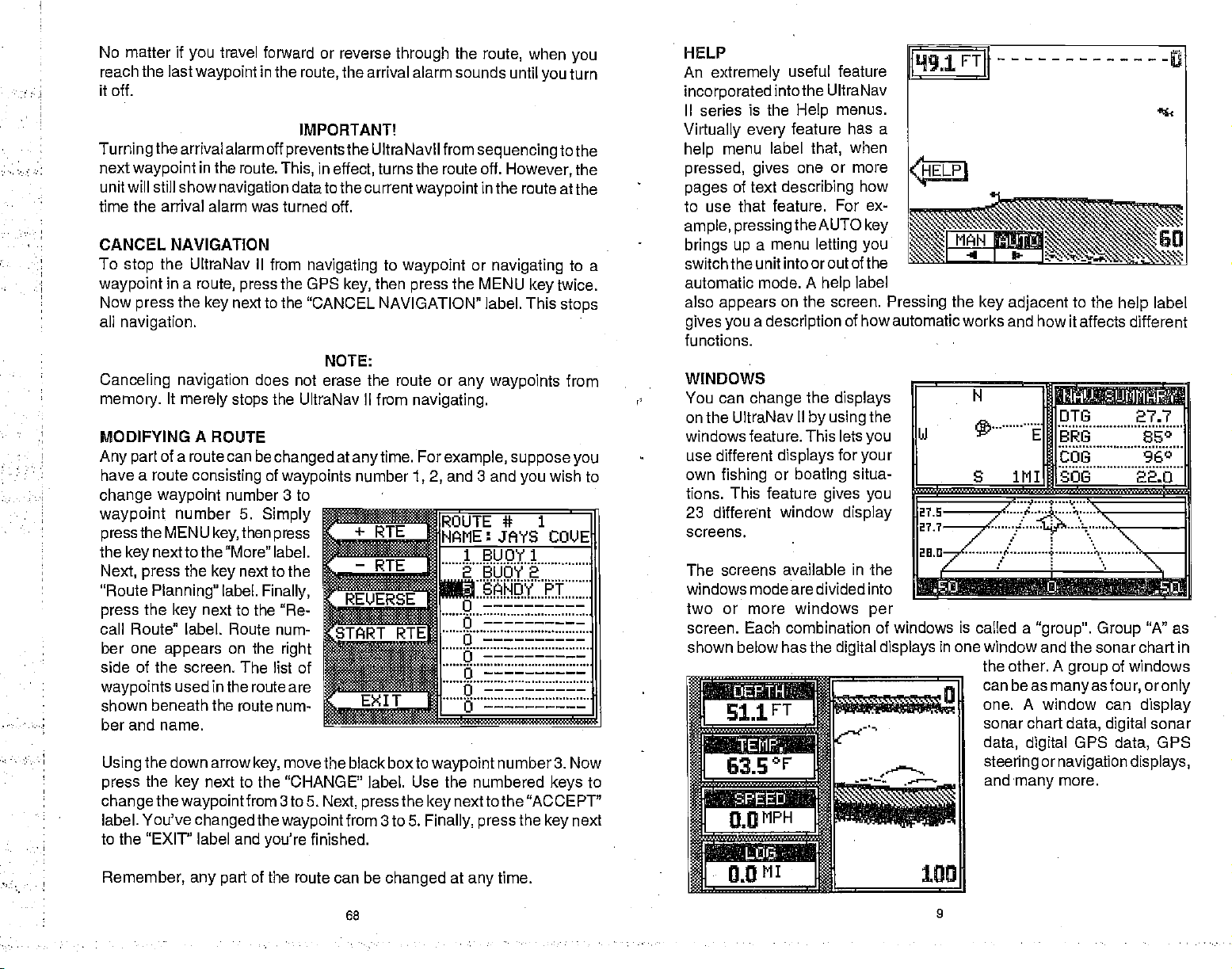
WINDOWS
You can
on the UltraNav
windows
use different
own
fishing
tions. This
23 different
screens.
The screens available in the
windows mode are divided into
two or more windows
screen. Each
shown below has the
useful
intothe UltraNav
describing
menu
a
on the screen.
change
feature. This lets
displays
or
feature
window
combination of windows is called a
feature
menus.
Help
feature has a
when
that,
one or more
how
For ex-
theAUTO
letting you
the
II
by using
boating
key
label
help
of how automatic works and how it
displays
the
you
for
your
situa-
gives you
display
per
digital displays
Pressing
the
key adjacent
to the
affects different
_______________________
N
itt
in
one window and the sonar chart in
the
can beas
one. A window can
sonar chart
data,
steering
and
___
JH]DTG
FIU3
COG 96°
SOB
1MIIH
"group". Group
A
other.
many
group
manyasfour, oronly
data,
GPS
digital
ornavigation
more.
digital
label
help
27.7
"A" as
of windows
display
sonar
GPS
data,
displays,
Remember,
any part
the route can be
68
changed
at
any
time.
9
cf
PDF compression, OCR, web-optimization with CVISION's PdfCompressor
Page 14

To
use the windows
flrstpressthe
A
screen similar to the
shown at left
menu af the
screen
the
"pages"
are lettered "A"
Group
WINDOWS
Ietsyou
"A" shows
switch
of
displays.
the down arrow
forward
Press the
move backward.
pressing
once shows
screen which
screen. To return to the full
sonarscreen,
SONAR
one of the
•
•
Every
example, press
labels
appear
window menus.
labels
gives you
example,
ADJUST
—
TURN FISH
ru
THESE
AFFECT ALL
FULL
T1
arrow
up
the
down arrow
the
is the side scan
simply pressthe
key.
on the
key
Forexarnple,
group
group
the
MENU
display
Pressing
a menu with
if
you press
——
UJINDObJS AND
SCREEN CHART.
the
SRAYLINE
ID OFF
ADJUSTMENTS
4W
to
key•
"B"
screens can
key
as
the
key
functions that relate
key adjacent
CHART
be modified to some extent. For
while
group
shown above. Two of these labels are
adjacent
to one of the "window
to the window menu
sonarchartwindow,
will clear
new
as "ADJUST
and "ADJUST GRAYLINE"as
shown at left. Other window
menus
of measure or
To exit from a window
press
through
"A" is
displayed.
to that
only
and
you
menu with selections such
CHART SPEED"
letyouchangethe
the CLEAR
feature,
key.
one
appears.
bottom of the
through
first. Press
key
the
window. For
label on the
adjust
The
between
These
"W".
to move
screens.
Four new
menu"
the screen
will have a
units
alarms.
menu,
key.
The cursor should now be on the second
next to the "CHANGE" label and enter
key
second
the
the "EXIT"
You
other
1, 3,
this
the
FOLLOWING A ROUTE
To follow a
"More"
press
appears.
list of
route are shown beneath the
route number and name. If
wish to recall a different
pressthe key
or"-RTE"
waypoint
waypoints
must select
words,
and 5.
case,
you
route.
label.
the
key
Route number one
waypoints
Iabelstocyclethrough
the available routes.
After
you've
sired
route,
box
surrounding
waypoint
the
wish to start the route
first
label.
simply
waypoint
To follow a
For
numbered
shownavigation datatowaypointnumber3first,
travel backward
2
first,
in the route. This is
starting waypoirit
waypoint
However,
use the down arrow
number. Then
example, suppose you
then
in the route. Continue
have been entered for the
label. This saves
waypoints
suppose you
However, you
must
route, press
Next, pressthe key
next to the "Recall Route" label. The screen shown below
used in the
nexttothe "+RTE"
want a
wish to travel to 3
select
waypoint
the MENU
route,
route in
your
IMPORTANT
in the order
route that consists of
nextto the "Route
appears
you
SE
selected the de-
notice a black
you'll
the first
u
:flfl_flflfl
.
box. If
you
the
using
in the
route,
simply press
if
wish to start the route
you
to move the black
key
the
press
route
3,6,
6,
and
backwards,
2. If
and
through
end with
press
have three
travel
you
the
route,
waypoint
waypoint
the
entering
route. Then
memory.
are to be used in the route. In
they
and 5 in that order
3, 1,
then
key,
on the
RTE
li
fl
EXI
T
=
the
key
next to the "START RTE" label.
key
the
forward
the unit will start with
next to the "REVERSE" label.
key
waypoints
through
number 3.
line.
Again, press
waypoint
the
then
first,
press
Planning"
side of the screen. The
right
number for the
waypoints
the
press
waypoint
and
1,
when
the
key
label.
finally
next to the
ROUTE* 1
NAME:
.t..UQt1
JAYS COVE
2 BUOY 2
9
BUOY 3
o
ci
ci
U
j
next to the
using
in a route and
the
then
"START RTE"
a different
box to the desired
route,
and
6,
finally2.
waypoint
the
until all of
next to
key
numbers
5.
In
making
Finally,
waypoint,
they're
the unit will
If
you
number
PA9E1MORE
10
PDF compression, OCR, web-optimization with CVISION's PdfCompressor
67
Page 15

This menu lets
the
waypoints
a Route
Name
To
assign
label to move
appears
until the black box moves to the "NAME"
a name to a
in the window at the
select the route
you
used in the route.
route,
press
through
the list of routes. When the
top
number,
the
of the
name the
next to the "-i-ATE"
key
screen,
press
position.
to the "CHANGE" label. The screen shown below
Use the
the screen to
name. For
route"REEFl",
ber "4"
letter "R"
dow.
Next, press
row
key
to the next
the "1"
press
appears
this
process
name has been wriften on the
screen. Now
UltraNav
in the route.
used
on both sides of
keys
enterthe
example,
key repeatedly
appears
waypoint
to name a
pressthe
until the
in the win-
the
right
num-
ar-
to move the black box
letter
position.
The letter"E"
key.
on the screen.
until the entire
press
II returns to the route menu. You can now enter the
the
Now
Repeat
next to the "ACCEPT" or "ENTER" label. The
key
route,
desired
Now
appears.
route number
the down arrow
the
press
and
choose
or "-RTE"
key
waypoints
key
next
VIEWING
To see all of the
dows, press
key,
Now
the "MAIN
nally, press
'VIEW
The screen
The firstwindow
upper
A
description
shows in the box at
to the "NEXT' label. This
When
SIDE-SCAN OPERATION
Twp different side scan
Windows mode. To use the side scan
transducer
UltraNav
Now
key
right appears.
WINDOWS
available win-
WINDOWS
the
then
press
ALL WINDOWS" label.
right
you've
press
until the screen shown at
the MENU
press
the
key adjacent
MENU" label. Fi-
the
at
cornerof
on
Il unit.
next to the
key
right appears.
appears
the screen.
of the
finished
your trolling
the down arrow
This is
screen
the bottom of the screen. Now
viewing
displays
key.
in the
changes
motor.
group
_______________________________
to
WATER
the
the
windows,
are available when the UltraNav II is in the
Next,
0
FEET
I
Digital Depth
DEPTH DISPLAY.
DEPTH
UNITS OF
ARE SET IN MENU.
displayed
feature,
press
ALARMS AND
MEASURE
the
press
window and
the
press
first install the ScanPac
the WINDOWS
key adjacent
description.
CLEAR
key
I
key.
on the
Waypoint
If
you've
screen. If
H
keys.
below
Now
of the
first in the route. For ex-
to
ample,
number 8to be
key.
waypoint,
spacetothe rightofthewaypoint
number.
next to the "ACCEPT" label.
The UltraNav II reverts to the
menu shown above.
Selection
named a
not,
Now
appears.
press
waypoint you
if
you
If
you've
route,
move the
the
press
the numbered
want
first,
named the
it shows in the blank
Next,
press
the black box should be on the "0"
black box to the
next to the "CHANGE' label. The screen shown
key
key
wish to
go
"0"using
RTE# 6
NAME REEF1
the
atthetop
or down arrow
up
I U
waypoint
the 8
press
the
key
66
U
0
of the
are the side scan win-
These
dows. Bothwindowsshowthe
digital depth display
transducer
tom
ducer. The window
shows a Fish ID
the unit identifies
display
shows the
a fish
The window on the
short,
The
pointed
-
Not the side scan trans-
at the bottom of the
distance from the side scan transducer to the
symbol.
horizontal lines.
distancetothesetargets
of the echo to the
from the
at the bot-
on the left
symbol
a
target
right
range
when
as a fish. When this
shows all return echoes. These echoes
The thicker the
markers on the side of the
LS
ni
FISH 36.5 FT
flL__
window
can
changes
line,
be
determined
11
11!FDcPTH
happens,
from
"DEPTH" to "FISH" and
the
stronger
bycomparingthe position
the
target
the
display.
48.1
digital depth
shown as
appear
return echo.
as
PDF compression, OCR, web-optimization with CVISION's PdfCompressor
Page 16

To
change
bottom of the
the
display.
of the side scan
you've changed
the
press
Group
group
scan
windows.
summaryon
plete
groups.
CLEAR
"L" as shown
"U" also
displays
along
See the
page39foracom-
of all the
listing
Use
the
the RANGE
up
range, press
modefrom ten to
the
key
at
range
to
right
and the
erasethe
and
use the side
with other
windows
window
or down
key.
sixtyfeet.
menus will
menus.
A new menu
arrow
keys
Eitherwait
automatically disappear
appears
to
change
afew seconds
—'--I'
the
at the
range
after
or
next to the "WPT
key
Now
"÷ WPT" or
the
desired
appears
does,
to
the "GO TO WYAPOINT"
label. The UltraNav II returns to
the last used
orplotterscreen, showing
gation
recalled.
ROUTES
A route
to
re-program
more
navigation
the
firstwaypoint, (signalled bythe
the
press
"-WPT" label until
waypoint
on the screen. When it
simply pressthe key
sonar,
data to the
gives you
the unit after
waypoints.
information to the
cally sequences
this
in a
waypoint
route,
and the
the arrival alarm sounds until
RECALL' label. The
next to the
key
number
next
navigation,
navi-
waypoint you
the
abilityto navigate
arriving
When
to the next
travell on a
you
waypoint. Navigation
process
ILON
to
at
each one. A route
first
waypoint
Arrival
repeats.
screen shown
J.iJPT#
1
NAME
LAT
several
the
route,
in the route.
Alarm),
When
you
turn it off.
you
below
appears.
UERD BROS
N
36°09.869'
bi
95°37.171'
waypointswithout
consists of two or
UltraNav It first shows
When
the
UltraNav II automati-
information is shown to
reach the last
having
reach
you
waypoint
SONAR OPERATION
When the UltraNav
This is indicated
Automatic feature
in
displayed
To turn
bottom
the lower half of
Automatic
of the screen
-
AUTOMATIC
II is first turned
the word
by
adjusts
off,
the sensitivity
first
press
above
theleftandrightarrows.Press
the left arrow
the manual
"Man"
appear
corner
ing
mode. To turn Automatic
press
then
of the
the
unit
the AUTO
the
press
to switch
key
mode. The
in the
upper
display,
is in the
indicat-
manual
key
arrow
right
to
letters
left
on,
again,
key.
the Automatic
on,
"AUTO" at the
and
range
the screen at all
the AUTO
_________
151.2
key.
FTIF 0
feature is enabled.
of the screen. The
top
so
the bottom
times.
A
menu
appears
signal
at the
is
There arefour
steps required
create and name the route.
Then determine the
Finally,
the unit will
After these
navigation
CREATING A ROUTE
create a
To
MENU
data to the first
route,
white the unit is in
key
the OPS mode.
next to the "More" label.
key
Now
press
the
steps
first
Next,
key
starting waypoint. Next,
askyou
are
press
pressthe
next to the
"ROUTE PLANNING" label.
Finally, press
the
key
the "SAVE/EDIT ROUTE" la-
bel. The screen
appears.
shown.at
to create
Next,
if
wish to run the routeforward
you
completed,
waypoint
the
next to
right
and follow a route.
select the
waypoints
tell the unitto
the UltraNav II
on the route.
.
TE
aRTE
First,
used in the
follow the route.
orbackward.
will start
RQUTE4@
HAME:
must
you
route.
showing
1
::::::g:::E:EE:E:
gEEEEEEEE
12
65
PDF compression, OCR, web-optimization with CVISION's PdfCompressor
Page 17

Use the
the screen to
name. For
waypoint
letter "C"
the
window.
arrow
key
box to the next letter
Now
press
until the "0"
edly
.
the screen.
until the entire name
cess
nextto the "ACCEPT" or"ENTER" label. The UltraNav Il
key
waypoint
first
name,
to the "EXIT" label to exit the
Erase a
The
Waypoint
To erase
the WAYPT
next to the "WAYPT SAVE"
key
label. The screen shown at
appears.
on both sides of
keys
enterthewaypoint
example,
"COVE
key repeatedly
Next, press
to name a
1",
press
appears
the
the
until
in the
right
to move the black
position.
the "3"
save menu as shown above. To save the
press
Waypoint
awaypoint,first press
Now
key repeat-
appears
Repeat
key,
this
the
Erase feature lets
then
press
key
press
the
next to
on
pro-
has been written
"SAVE" label. Now
the
waypoint
the
save menu.
erase
you
r7IUJPT#
]NflI1E
JLAT
right
key
on the screen. Now
waypoints
ILUN bJ 95°37.1?t'
the
press
returns tothe
waypoint
press
with this
the
key
next
from the list.
L'ERIJ BROG
N 36°09S69'
next to the "÷ WPV' or "-WPT"
label until the desired
numberappears
Simply press
the
"ERASE" label. A
appears
"WAIT!!
on the screen that
DELETE
ARE YOU SURE?." If
erase, press
the
"NO" arrow. Press the
informationfromthewaypoint numberthatappears atthetop
To exit from the
waypoint
onthescreen.
nexttothe
key
message
says
WAYPOINT
are certain this is the
you
next to the "YES" arrow. If
key
next to the "YES" arrow erases all
key
save
waypoint
menu,
press
waypoint
not, press
the CLEAR
that
the
key.
wish to
you
key
ofthescreen.
next to
SENSITIVITY
The
sensitivity key
echoes. A
up
fish
signals,
to see this
you
signals.
signal
When the UltraNav
Typically,
with
Grayline
cally adjusted
This
However,
it the
gives
situations occur where it becomes
on the UltraNav II controls the
lowsensitivitylevel
and other
detail,
target
but it can also clutterthe screen with
the best
excludes much of the
information.
sensitivity
and some surface clutter.
II is in the Automatic
to
a
keep
capability
solid bottom
to show fish and other detail.
High
level shows a
mode,
signal displayed, plus
decreasethesensitivity.This typically happens
so an increase in
detail,
same whether the unit is in the automatic
is the
To
appears
The
The
the
adjust
sensitivity, press
at the bottom of the screen.
sensitivity
graph gives
menu
abovethe INC arrow also
the
percentage
use.
increasethe
To
the
press
you press
bar
graph
the
percentage
value.
difference on the chart record
You can
of
sensitivity
arrow
right
the
key,
will
grow
will increase in
sensitivity
has left and
a visual indication of the
shows
sensitivity
level,
key.
the menu's
wider and
see the
also
is indicated. The
the SENS
right
in
As
key.
arrows,
sensitivity
as it scrolls. When the sensitiv-
is at the desired
ity
lease the
key.
To decrease the
The bar
desired
graph
level,
and
release the
sensitivity
percentage
level,
re-
press
the
key adjacent
level,
will decrease. When the
key.
the
of
ability
bottom
sensitivity
the
sensitivity
levels
many
solid bottom
good
information,
a little
necessary
whenyouwishto
or manual mode.
The
sensitivity adjust
a horizontal bar
plus
to increase or
procedure
level. The number
to the left arrow.
sensitivity
unit to
enables
undesired
is
automati-
more.
see more
to
adjust
menu
graph.
is at the
pick
it
-U
RECALL A WAYPOINT
You must recall a
UltraNav II. To recall a
waypoint
in order to
waypoint,
navigate
first
press
64 13
to that
the WAYPT
position
key,
then
with the
press
the
When
To turn the menus
bottom left side of the unit or wait a few seconds and the menus
disappear.
reach either the maximum or minimum
you
off, press
the
key adjacent
a tone
limit,
to the CLEAR
sounds..
at the
key
will
PDF compression, OCR, web-optimization with CVISION's PdfCompressor
Page 18

RANGE
When
bottom
and is
manually
RANGE
The UltraNav II
mode.
To
mode.
key.
menu
cornerof the
up
crease or increase
The available
10, 20, 30,
-
Automatic
turned on for the
in the
signal
of the
part
while the
-
Manual
gives
change
the
range,
Next,
pressthe
The
range adjustment
appears
iii the
display.
or down arrow
ranges
40, 60,
first
time,
lower half of the
automatic
unit is in
lower
Press the
keys
the
100, 150,
automatic.
control over the
you
first
make certain the
RANGE
right
to de-
range.
are
0-5,
200,300,500,800,1000, 1500,
2000, 3000,
ter the desired
played, press
to erase the
NOTE: The
installation,
and 5000
range
the
CLEAR
menu.
range
depth
capability
water and
feet. Af-
is
dis-
key
of the UltraNav II
bottom
the
UltraNav II
screen. This is called
function. The
range
conditions,
and other factors.
automatically places
Auto
cannot be
range
when
its in the
UltraNav
depends
II is in the
on the
the
Ranging
changed
manual
manual
transducer
Enter New
To save a
Then
key.
below
down
"CHANGE FIELD" label at the
bottom
screen. Use the arrow
change
latitude is
location
the numbered
left
arrow
make a mistake. In other
you
words,
moves the black box over
key
the
last number entered. No-
tice that the
in
degrees, minutes,
you've
waypoint
FIELD"
to
east,
to the
is 85
when
entered in the
you
position
Waypoint
location otherthan
the
press
appears. Using
to the
right
the "N" to a
south.
wish to save
you
key
pressing
position
entered the
save menu
label. Press the down arrow
if
necessary.
longitude
degrees,
you've
is
correct, press
key
latitude/longitude
corner of the
"S",
Now
keys.
as a
backspace
the left arrow
entered is
latitude, press
reappears. Next,
Now enter the
if it's less than 100
then enter "085".
finished. The save
waypoint position
your present position,
next to the 'WPT SAVE"
the
up
to
keys
if
your
enter the
using
Use the
and
hundredths of a minute.
the
and down
position.
arrow
Now
IJ
if
the
Press the
waypoint
next to the "SAVE"
key
nextto the
key
press
to switch
key
longitude.
degrees.
key
menu
box at the
first
press
label. The screen
move the black
keys,
the
press
I:,i+#
.,I
NAME
LAT
L0N
USE NUMERIC
TO
UP=
the
key
the
Make
For
example,
next to the
appears
top
key
N !—°——,———'
...TTTCT
CHANGE LJALUE
"N1' Q=
(Not
seconds!)
"ACCEPT" label. The
nextto the "CHANGE
longitude
certain to add a
"ACCEPT" label
with the
of
the screen. If this
label.
the WAYPT
next to the
KEYS
from west
if the
longitude
position
shown
box
After
zero
ZOOM
Enlarging or"zooming"the
detail and fish
a
plus
screen zoom
split
signals.
The UltraNav II
different in the automatic
ZOOM
To zoom the
targets
AUTOMATIC MODE
display
in the
are
display
on the
The menus shown at the
Turn the zoom feature on
ON" label.
(or
H
picture
option.
is acommon
The
and manual
automatic
of
the
four times
next
14
enlarged
top
off) by pressing
gives you
zoom
operation
modes.
first
mode,
page
the
method used to show
two different zoom
and
adjustment
the
press
normal size
also
key adjacent
ZOOM
appear.
key.
automatically.
to the "OFF!
small
sizes,
is
All
Name a
To
next to the
the
WPT"
the list of
desired
wibdow,
key
the "NAME"
the
FIELD" label. The
at
Waypoint
assign
a name to a
waypoint, press
'WPT SAVE" label. The
next to the "+WPT" or
key
label to move
waypoints.
waypointappears
the down arrow
press
until the black box movesto
position
next to the
key
through
When the
inthe
Now
press
"CHANGE
screen shown
right appears.
the WAYPT
waypoint
63
then
key,
save menu
press
appears.
the
Press
key
PDF compression, OCR, web-optimization with CVISION's PdfCompressor
Page 19

Saving
•
•
•
(Quick
The UltraNav II lets
one
of a wreck or other locations.
Present Position
Save
Feature)
key press.
This "Quick Save" feature lets
you saveyour present position
as
a
Waypoint
as
awaypointwith only
you easily
save the
position
Pressing
the "2X/4X" label
oesfromtwotimestofourtimes
their normal size.
the
key adjacent
enlarges
to
ech-
•
•
I The "Quick Save" feature doesn't let
To save
QU
the first
Saving
have to use the next available number when
and Save method lets
position
number that
save
your present position
ICKSAVE
available
Present Position - View and Save Method
is stored in.
your present position, press
The UltraNav II takes
key.
waypont
you pick
(Note:
already
has a
as
number to it.
the
You can store
position assigned
the WAYPT
to the "V/PT SAVE" label. A screen similar to the one
The first
the list
appears
This is the number that
page.
present position
your
the
WAYPT
"CURRENT POSITION" box in
under. Your
time
the middleof the screen. If
wish to save the location in the
CURRENT POSITION box un-
der this
ply press
• position
waypoint
naming it; simply press
To save the location
number ito
waypoint
location
label. Then
location under the
used
position, plot,
waypoint
you pressed
key
waypoint number,
the
shown in the
location at the
number. Once
under, press
press
number in
at the
is shown in the
of the
top
will be
position
at
ar
the
FJ
you
EHT
H4NGE
sim-
next to the "USE CURRENT POSITION" label. The
key
CURRENT POSITION
of the screen. To save the
top
Press the
2).
the
underadifferentwaypoint
to increase
you've
the
the
key
waypoint
or
navigation
next to the "SAVE" label.
key
the
next to the
key
decided the
next to the "USE CURRENT
key
next to the "SAVE"
number
screen.
waypoint, simply press
yourpresent
select the
you
using
waypoint
a
key.
ILON
waypoint
"-
WPT" label to decrease the
waypoint
selected and return to the last
you
position
waypoint
that method. The View
number that
position
to it
CJJPRENT.F'iJi.T1ON
box also will show in the
number,
number
under a
this
using
Now
press
below
_.c'__•.__'
N
H 36°08.866'
Ui 96°EQ.441'
waypoint
press
(i.e.
number to save the
label. This will store the
the
WAYPT
and
assigns
number. You
your present
waypoint
method.)
the
appears.
FIELD
the
from
POSITION"
To
next
key
I....
without
next
key
waypoint
of the ones on the
size
on the left side
the
right.
echoes on both sides of
side. This feature tracks the
when.the
the CLEAR
press
ZOOM
When
screen shown below
identically
shown when the unit is in the manual
To
screen
appear
ones
the
ove the zoom bar
As
echoes move on the
-
you
adjust
similar to the one below
on the screen. The echoes on the left side of
that
or down
up
adjustthe
you
of the screen are shown at twice the size as the ones on
The echoes that
automatic feature
key
MANUAL MODE
the zoom
press
described above.
as
the
zoom,
appear
press
between the
arrow
or down.
up
zoom
left side of
If
right.
scroll across the screen are
the screen.
erase the menus.
to
key
appears.
keys
the
bar,
switch to the 2X zoom
you
bottom, keeping
is on. Once
while the unit is in the manual
All of the menus on this screen work
However,
the
key adjacent
appears.
and the bottom of the zoom bar. Press
top
to
hst ri
the screen at the same time.
zoom
The
automatically
onds after
last
UltraNav
tom when it's in the
mode.
adjust
you've pressed
key.
II won't track the bot-
menus will
clear a few sec-
Remember,
manual
the
the
To switch between the
screen zoom and full screen
zoom, press
tothe "SPLIT/FULL' label. The
screen
sections. All
are shown at four times the
the
key adjacent
instantly splits
targets
mode,
the exact same
They're simply enlarged
it on the
you've
one additional menu item is
mode: "ADJUST".
A zoom bar and
display
set the zoom as
to the "ADJUST" label. A
adjust
screen are the
th.e
37.3
tafl
at all
split
into two
on the left
echoes
on
the left
times,
desired,
mode,
the
arrows
0.
62
15
PDF compression, OCR, web-optimization with CVISION's PdfCompressor
Page 20

MENU
-
PAGE 1
CHART SPEED
The rate
the screen
speed.
pressing
pressing
the
label. The chart
appears
echoes scroll
is called the
it's
adjustable
the menu
the
key adjacent
"ADJUST CHART
speed menu
at the
bottom of the
screen. Increase
speed
row
by pressing
or
decrease it
key
across
chart
by
then
key,
SPEED"
the chart
the
right
by
pressing
first
to
ar-
the left arrow
chart
the
arrow
The bar
graphical
speed.
on the
and
on the chart
press
madethe
CLEAR
The
key.
speed
percentage
in use
keys
chart also
indication of the
You
can seethe
screen
(both
record)
the
keys.
adjustment,
erasethe menu.
keytb
changes
are
pressed.
gives
change
on the
After
press
of
as
a
chart
menu
as
you
you've
the
cursor. To
one of
makes the
appear
move the lines to the
pôsitionon
the arrow
ing
the desired
EVENT MARKER
select an
places
tion of the
To
erase the cursor
Erasing
Although you
do
the arrow
plotter
on the
the
location, press
icon. The UltraNav II
the
icon at the intersec-
ploçter
first
this,
keys.
cursor lines
display.
desired
displaybypress-
When
keys.
key,
cursor lines.
lines,
the Icons
can
place
press
This
Now
it's at
the
then
press
icons on the
them one at a time. You have
example,
if
you've place
20 fish
all 20.
To erase an
next
to the "DELETE ICON BANK"
appears.
icon,
first
press
the EVENT
SO.?
.
22,0
s
the
CLEAR
plotter individually,
to erase the
symbol icons,
MARKER
label. The screen
UJ 95*5O.496
W
key.
whole
group
erasing
one of them
key. Next, press
can't
you
erase
of icons.
erases
the
shown below
E
For
key
To
start the
chart,
GRAYLINE°
GRAYLINE lets
"paints" gray
to tell the
you
soft,
muddy
a narrow or
causes a
If
have
you
then
the
weeds
GRAYLINE is
strong
GRAYLINE
on
difference
or
weedy
no
wide
two
target
from trees on
adjustable.
and weak
level, also. The level
the
press
you
targets
gray
line.
gray
signals
with
gray
the
signals, adjusting
key adjacent
distinguish
that are
between a hard and
bottom returns a
line.
A hard
of
equal size,
is the
bottom,
Since
To
adjacent
to the 'START"
between
stronger
than a
weaker
bottom returns a
one with
stronger signal.
or
fish from
GRAYLINE
the
chosen
16
showsthe difference
sensitivity
by
the
stop
to
strong
the
and weak
preset
soft bottom.
signal
strong
and
gray
This
structure.
may require
UltraNav II at
chart, press
the
the "STOP" label.
label.
echoes. It
value.
This allows
For
which is
example,
shown with
which
signal
the other
without,
helps distinguish
between
a
different
on is
power
key
a
Now
select the
thatyou
ing
icon.
UltraNav Ii erases all of
selected icons
wish to erase
the
next to the desired
key
Afterpressing
from the
group
the
of icons
by press-
the
key,
the
plotter.
WAYPOINT NAVIGATION
HOW TO SAVE A WAYPOINT
are
Waypoints
to.
Waypoints
otherfishing
memory
afew buttons.
your present position
waypoints.
locations on the earth's surface that
are
useful for
or
makes
navigation
iteasyto
locations.
return to
The UltraNav II can store
as a
waypoint
Ma0O9.Oo2
'I?
,
''
SELECT
GROUP TO ERASE
FROM
'is,
156°
marking shipwrecks,
Storing waypoinfs
in the
any point
upto
or enter
61
world
200
waypoints.
latitude/longitude positions
W
95°50.389'
AN ICON
PLOTTER.
I4ARNING!
wish to
you
hot
go
fishing spots,
in the UltraNav Ti's
bysimply
You can
or return
and
pressing
store
as
PDF compression, OCR, web-optimization with CVISION's PdfCompressor
Page 21
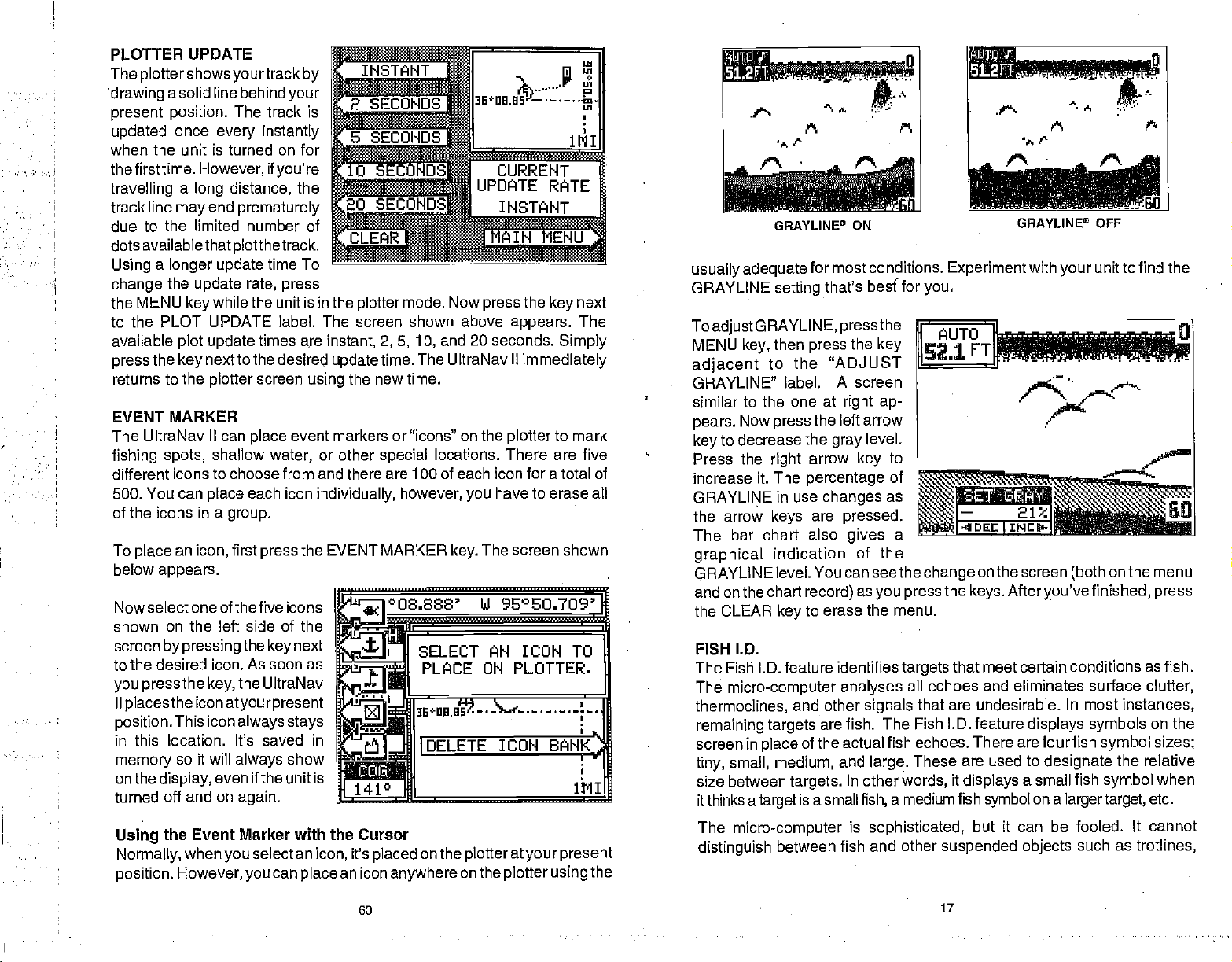
PLOTTER UPDATE
The
plottershows yourtrack by
drawing
present
updated
when the unit is turned on for
the tirsttime.
travelling
track line
due to the limited number of
dots available that
Using
change
the MENU
asolid line
position.
once
a
may
a
longer update
the
The track is
every instantly
However,
distance,
long
end
plotthetrack.
update rate, press
while the unit is in the
key
behindyour
if
you're
the
prematurely
time To
to the PLOT UPDATE label. The screen shown above
available
press
returns to the
EVENT MARKER
The UltraNav
fishing spots,
different
500. You can
plot update
the
next to the
key
plotter
II can
icons to choose
place
of the icons in a
To
below
Now
shown
screen
an
place
select one of the five icons
icon,
appears.
on the left side of the
by pressing
place
shallow
each icon
group.
first
the
times
desired
screen
event markers or "icons" on the
water,
from and there
press
next
key
to the desired icon. As soon as
you pressthe key,
II
placestheiconatyourpresent
position.
in this location. It's saved in
memory
on the
turned off
•
•
Using
Normally,
position.
This icon
so it will
display,
and on
the Event Marker with the Cursor
when
However,
the UltraNav
always stays
always
even if the unit is
again.
you
show
select an
can
you
__________
—I--
SECONDS Iib*DD.US t 2
______
•
SECONDS
_____________
_______________
20 SEC0NDSW
a ENU
mode.
plotter
aye instant, 2,5, 10,
update
using
or other
individually,
the EVENT MARKER
time. The UltraNav II
the new time.
special
are 100 of each icon for a total of
however,
''i°O8.888'
0
SELECT
PLACE UN PLOTTER.
UPDATE RATE
INSTANT
_______________
___________
Now
press
and 20 seconds.
locations. There are five
have to erase all
you
The screen shown
key.
LI 96°SO.709'
flN WON TO
jj
3tflfljP._..S%d-.-._.—.-1_.
IDELETE
on the
placed
anywhere
plotteratyourpresent
on the
ICON
plotter
icon,
place
N
th
141°
it's
an icon
URRENT
the
key
appears.
Simply
immediately
to mark
plotter
BANK
using
next
The
1111
the
GRAVLINE°
usually adequate
GRAYLINE
ToadjustORAYLINE,
MENU
adjacent
GRAYLINE"
similar to the
pears.
key
Press the
increase it. The
GRAYLINE in use
the
The
key,
Now
to decrease the
arrow
bar chart also
graphical
GRAYLINE
and on the
the CLEAR
FISH I.D.
The Fish l.D. feature
The
micro-computer
thermoclines,
remaining targets
screen in
tiny,
size between
it thinks a
The
distinguish
place
small, medium,
target
micro-computer
for most conditions.
setting
then
to
press
right
keys
indication of the
level. You can seethe
chart
that's besf
press
the "ADJUST
label. A screen
one at
the
arrow
percentage
changes
are
record)
to erase the menu.
key
other
and
are
of the
targets.
is a small
between fish and other
!uu
r
..
ON
Experimentwith
for
you.
pressthe
the
key
right ap-
left arrow
level.
gray
identifies
and
to
key
of
as
pressed.
a
gives
changeonthe
as
you press
analyses
signals
fish. The Fish ID. feature
actual fish echoes. There arefourfish
large.
In other
a medium fish
fish,
is
sophisticated,
the
targets
words,
that meet certain conditions as fish.
all echoes and eliminates surface
that are undesirable. In most
These are used to
it
displays
suspended objects
GRAYLINE° OFF
your
.p-
screen
keys. Afteryou'vefinished, press
displays symbols
designate
a small fish
symbol
but it can be fooled. It cannot
on a
larger target,
unit to find the
?1aC12%&dLb,,
on the menu
(both
instances,
symbol
the relative
symbol
as
such
Ps
clutter,
on the
sizes:
when
etc.
trotlines,
60
17
PDF compression, OCR, web-optimization with CVISION's PdfCompressor
Page 22
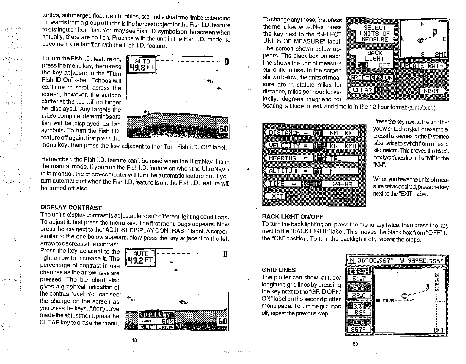
turtles,
outwards from a
to
actually,
become more
ToturntheFishj.D.featureon
pressthemenukey,thenpress
the
Fish-ID On" label.
continue
screen,
clutter
be
micro-computerdetermines are
fish will be
symbols
feature off
menu
Remember,
the
is
turn automatic
be turned off
submerged floats,
group
distinguishfromfish.
there
are no
familiar
key adjacent
to the
Echoes will
to scroll
however,
at the
displayed.
To
again,
key,
manual
in
manual,
then
mode. If
the surface
will no
top
Any targets
.displayed
turn the Fish
first
press
the
Fish I.D.
the
micro-computer
off when the
also.
air
of
limbs isthe
You
maysee
fish. Practice
with the
'Turn
across
you
the
longer
the ________________
as fish
l.D.
the
press
the
key adjacent
feature can't be
turn
Fish I.D.
bubbles,
the Fish I.D.
etc.
Individual tree limbs
hardest
Fish l.D.
with the unit in
Fish I.D. feature.
I AUTO I
]Lh198
will
turn the automatic
feature is
objectforthe
symbols
FTD
to the
"Turn Fish I.D. Off"
used when the
feature on when
on,
on the
the Fish
the
Fish l.D.
extending
Fish l.D.
feature
screenwhen
ID. mode to
———-0
label.
UltraNav II is
the UltraNav II
feature on. If
feature will
60
in
you
To
change
the menu
the
UNITS
The
pears.
line
currently
shown
sure are in
distance,
locity, degrees
bearing,
anythese,
keytwice.
next to the "SELECT
key
OF MEASURE'
screen shown below
The black
shows the unit of
in use. In
the units of mea-
below,
statute miles for
miles
altitude in
first
Next,
box on each
measure
the screen
hourforve-
per
magnetic
and time is iii the
feet,
press
press
label.
ap-
for
IE-
ELOCITY jj
IN6=-
UOE=M'
TIME
=
<N
24—HR
KMH
12 hour
format
(a.m.Ip.m.)
Press the
youwishtochange.
pressthekeynexttothe
label twice to switch
kilometers. This
box two times from the
'XM".
When
sure
setas
next to the
key
have
you
desired,
"EXIT' label.
next to the unit
Forexample,
from miles to
movesthe black
the units of mea-
pressthe key
that
Distance
"MI" to the
DISPLAY
The
To
adjust
press
similar to the one
arrowto
Press the
right
percentage
changes
pressed.
gives
the
contrast level. You can
the
you pressthe
madethe
CONTRAST
unit's
display
it,
the
key
decrease the
key adjacent
arrow to
as
The bar
a
graphical
change
adjustment,
to erase
key
contrast is
first
next to the
increase it.
press
below
the
"ADJUST DISPLAY
contrast.
of contrast in
the arrow
on the
keys.
keys
chart also
indication of
screen as
Afteryou've
pressthe
the menu.
adjustable
menu
appears. Now
to the
The
use
are
see
The
key.
FUTO
18
to
suit different
first menu
CONTRAST"
the
press
FT
DRK
I
lighting
page appears.
label. A screen
key adjacent
conditions.
Now
to the left
a
Go CLEAR
BACK LIGHT
To turn
next to
the
GRID LINES
The
longitude grid
the
ON" label on the second
menu
off,
the back
the "BACK LIGHT' label. This
"ON"
plotter
nextto the "GRID
key
page. Toturnthegrid
repeat
ONIOFF
lighting
position.
can show
lines
the
previous
To turn the
latitude!
by pressing
step.
on,
the
press
backlights off, repeat
menu
moves the black
H
36°O 836?' bJ
fl
rr
OFF!
plotter
lines
IA
22.0
830
i..........,.
59
key
twice,
box from "OFF" to
the
steps.
press
the
key
then
96°EO.S%'
—
aE÷na.as——
PDF compression, OCR, web-optimization with CVISION's PdfCompressor
Page 23

All of the
to the location
plotter displays.
CHANGE DISPLAY
The four
changed
after it's
Over Ground
Ground
windows are: Distance To Go
to
Water
To
digital displays,
MENU
showing.
navigation displays
you
digital
displays
or customized at will. When the UltraNav II is first turned
preset,
waypoint (BRG),
depth (DEPTH),
change any
the four
(SOG), Bearing
(COG).
The available
or all of the
first
while the
key
Now
press
marked. This includes the
on the left side of the
digital displays
Course Over Ground
and
Altitude
the
press
is
plotter
the
key
next to the "CHANGE DIS-
PLAY" label. The unit returnsto
the
box
This means the DTG box is
readyto
left or
the
change
Cross Track Error
To
change
flashing
until the desired
When
This locks the screen
screen with a black
plotter
surrounding
be
right
display.
the Distance To Go to
the DTG box.
changed.
arrow
keyto change
For
example,
(XTE), press
another
Pressthe
digital box, press
box is on the desired
display appears.
have the
you
digital displays customized, press
to
displays,
on the UltraNav II will show
navigation,
are Distance To Go
to
waypoint (BRG),
displays
(DTG), Speed
that can be
(COG),
(ALT).
Over Ground
Cross track error
plotter
and
navigation
steering,
screen can
(DTG), Speed
Course Over
placed
(SOG),
N 36°09,fl21' bi 95°SU.54O'
rk
N
700
L1'I
22.0
34°
the
right
display.
Now
even if the unit is turned off and on
the
.
arrow
key
or down arrow
up
the
press
four times.
or left arrow
right
the CLEAR
lii
key
data
and
be
or
on,
in
these
Bearing
(XTE),
2111
until the
key
key.
again.
SONAR
The UltraNav
Fish Alarm. It sounds
group
of a bar.
alarm is
alarm.
navigation.
To
appears.
adjust
the "SET DEPTH OR GPS
next
alarm has its own menu which
is shown and described in the
zone alarm section. Once
see this
arrow
on the
example,
selected,
next to the 'CHANGE VALUE"
label. Use the numbered
to set thealarm. For
ALARMS
II has three different
when
the
Fish
of
types
sonar alarms. The first is
l.D. feature determines an echo or
of echoes is a fish. Another alarm is the Zone Alarm which
echo that
Any
called
the
appears
Depth
This is useful as an anchor
See the GPS section for information on
alarm,
press
first
press
next to the "SET
key
or
deep digital
The zone
the down
alarm is
the
example,
an
adjust
Press the
the shallow
page appears.
screen, press
until the black box is
key
desired alarm. In this
the shallow
Now
inside this bar
Alarm.
Only
the
ALARM
alarms. When
ALARMS",
LET
yOu
key
watch,
triggers
the bottom
a
shallow water
The screen shown
key.
DEPTH OR GPS ALARMS" to
you press
the menu shown at the
DEPTH OR GPS
I_____ TURh FISH ALM ON
keys
E<IT TURN ZuNE
to setthe shallow alarm's value
to 10
feet, press
the 0
press
next to the "ENTER" label. The unit returns
When either
bottom of the screen. Press the "CLEAR"
alarm is
The
triggered again,
following
the 1
When the desired value has been
key.
depth
section
then
key,
alarm
sounds,
the alarm
describes each
a "Silence
will also sound.
sonar alarm and its limits.
to the ALARMS screen.
Alarm" label
mutethe alarm. When the
keyto
the alarm. The
will
signal
trigger
alert,
GPS alarms.
the
key
i'ILARMS
4LM ON
entered,
press
appears
consists
or for
below
next to
of the
top
the
at the
the
last
this
key
PLOTTER MENU
SELECT UNITS OF MEASURE
The UltraNav II can
velocity
magnetic
format.
in miles
or
-
PAGE TWO
display
perhour,
Altitude in feet or
true,
distance in
kilometers
FISH ALARM
Use the fish alarm for a distinctive audible alarm when fish or other
miles, kilometers,
or
hour,
per
meters,
58 19
knots,
and time in 12 hour or 24 hour
or nautical
bearing
miles,
in
degrees
suspended objects
sounds for each fish
are detected
symbol
size shown on the
by
the Fish l.D. feature. A
display.
different tone
PDF compression, OCR, web-optimization with CVISION's PdfCompressor
Page 24

ZONE ALARM
The zone alarm consists of
bar that
side of the screen.
that
between the
the zone alarm's bar
the zone alarm.
Note:Thezone alarm isn'tavail-
able in the Windows mode.
appears
appears
on the
Any
on the
and bottom of
top
will
right
echo
screen
"trip"
a
HE4LARM
.11
TURN FISH
URhZuNEALMQH
To set the zone
the ALARM
screen similar to the one
19L7FT11
Ii SET 2QNE
L0WER
<'CHINGE
a
The above
zone
the
"Turn Zone Alarm Off"label at the
Normally,
adjustments.
the
alarm
the zone alarm bar
"Display
alarm,
Now
key.
TO
UPPER!
steps automatically
off,
leave the zone
To
Zone Alarm Bar"
press
press
shown below
LIMIT
the
press
the
next to the "Set Zone Alarm"
key
appears.
The zone
the
Use the
the bottom of the bar
N
lower. To
E
bar,
the "CHANGE TO UPPER" la-
bel. Now use the arrow
move the
or lower. When
zone alarm bar set as
press
menus.
turn
the zone alarm on if it was off. To turn
ALARM
bottom of the screen.
disappears
alarm baron the screen all of the
section in this manual for instructions.
then
key,
from the screen after
alarm bar shows on
side of the screen.
right
arrow
move the
first
press
top
the CLR
the
press
LlI ON
keys
the
key
of
the
you
to erase the
key
key
label. A
to move
or
higher
of the
top
next to
to
keys
bar
higher
have the
desired,
next to the
make
you
see
time,
SET RANGE
Use this menu to
plotter's range
across the
range
UltraNav II is turned on for the
first time. The available
ranges
20,50,
you
tions in
out" to see
tion,
ICON
Pressing
the EVENT MARKER
Event Marker section. This also turns on all of the
ALARMS
Press this
see the ALARMS section.
plotter's display.
is 1 statute mile when the
are
.1, .2, .5, 1, 2, 5, 10,
and 100 miles. This lets
"zoom in"to see small varia-
your
present position,
ON/OFF
this
key
change
or distance
course or "zoom
your starting posi-
turns on the icons that
key
for the alarms menu. For more information on the
the
The
plotter
track, course,
For more
key.
and
destination.
placed
you
information on this
GOTO CURSOR
As
previously
highlightaposition.
hairs on the
next to the "GOTO CURSOR" label on the
UttraNav II to show
the cross hairs. This
To use this
the
plotter
the MENU
the
key
CURSOR" label. The unit re
turns to the
waypoint flag appears
screen
the location of the cursor cross
hairs when
next to the "GOTO CUR
key
SOR" label.
described,
display
feature,
screen.
key. Finally, press
next to the "GOlD
plotter
(numbered"O")thatwas
you pressed
the cursor lines can
When
are shown at the
navigation
automatically
first move the cursor lines to the
Next,
screen. A
usethecursorlines,
you
and
steering
turns the arrival alarm
press
N 36°09.067' Ui 96°SO.646'
U1fl N
______
065
the
_______
______
th
_______
2700 S 21'lI
on the
top
770
be used to
of the screen.
plotter
data to the
Ui
on the screen
feature,
waypoint icons,
an icon or
place
the
position
menu causes
desired location on
ofthecross
Pressing
position
on,
shown
also.
using
see the
also.
alarms,
the
key
the
by
E
20
57
PDF compression, OCR, web-optimization with CVISION's PdfCompressor
Page 25
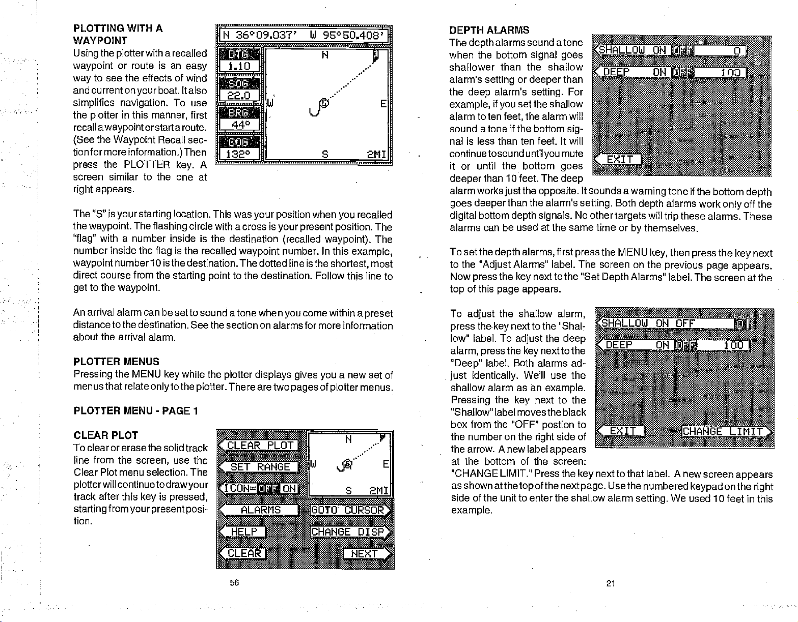
PLOTFING WITH A
WAYPOINT
Usingthe
waypoint
•
•
•
•
•
•
way
andcurrentonyourboat.
simplifies navigation.
recall
(See
tionfor more
press
screen similar to the one at
The "5" is
the
"flag"
number inside the
waypoint
direct course from the
get
plotterwith
or route is an
to see the effects of wind
plotter
waypoint.
to the
in this
awaypoint
the
Waypoint
information.)
the PLOTTER
appears.
your starting
The
with a number
number 10 is the destination. The dotted line isthe
waypoint.
arecalled
easy
Italso
To use
manner,
orstart a route.
flashing
flag
first
Recall sec-
Then
A
key.
location. This was
circle with a cross is
inside is the destination
is the recalled
starting point
36°09.037' W 95°EQ
a
1.10•
s
22.0
—
132 S
waypoint
to the destination.
'
W
fi
your position
your present position.
when
(recalled waypoint).
number. In this
Follow
403'
/•
/
.....
recalled
you
example,
shortest,
this
2M1
The
The
most
line to
DEPTH ALARMS
The
when the bottom
shallower
alarm's
the
example,
alarm to ten
sound a tone if the bottom
nal is less than ten feet. It will
continuetosound until
it or until the bottom
deeper
alarm works
goes deeper
digital
alarms can be used at the same time or
To setthe
to the
Now
top
alarms sound atone
depth
than the shallow
setting
deep
than 10 feet. The
bottom
"Adjust
press
of this
or
alarm's
if
set the shallow
you
feet,
the
just
than the alarm's
depth signals.
alarms,
depth
Alarms" label. The screen on the
the
key
page appears.
signal goes
deeper
setting.
the alarm will
than
For
sig-
mute
you
goes
deep
opposite.
No other
first
press
next to the "Set
It sounds a
setting.
Both
targets
the
MENU
Depth
tone if
warning
depth
will
trip
themselves.
by
key,
previous page appears.
Alarms" label. The screen at the
the bottom
alarms work
these alarms. These
then
press
only
the
key
depth
off the
next
An arrival alarm can be set to
distance to the
about the arrival alarm.
PLO1TER MENUS
Pressing
menus that relate
PLOTTER MENU - PAGE 1
CLEAR PLOT
To clear orerase the
line from the
Clear Plot menu selection.
plotterwillcontinuetodrawyour
track after this
starting
tion.
destination. See the section on alarms for more information
the MENU
from
your present posi-
only
solid track
screen,
is
key
key
sound atone when
while the
to the
plotter.
use
the
The
pressed,
come within a
you
plotter displays gives
There are two
58
pages
a new set of
you
of
plotter
preset
menus.
To
adjust
press thekey
low" label. To
alarm,
"Deep"
just identically.
shallow alarm as an
Pressing
"Shallow" label movesthe black
box
the number on the
the arrow. Anew label
the shallow
next to the "Shal-
the
adjust
the
press
label. Both alarms ad-
the
from the "OFF"
next to the
key
We'll use the
example.
next to the
key
postion
right
alarm,
deep
to
side of
appears
at the bottom of the screen:
"CHANGE LIMIT."
as
shown
side of the unit to enter the shallow
example.
atthetop
Press the
of the
nextpage.
next to that label. A new screen
key
Usethe numbered
alarm
21
setting.
We used 10
keypad
appears
onthe
right
feet in this
PDF compression, OCR, web-optimization with CVISION's PdfCompressor
Page 26

After
you've
sired
alarm
next to the
key
bel. This enters the alarm
ihto
memory
turns
theshallowalarmon. Now
the
press
CEPT' label.
entered the de-
depth, press
"ACCEPT"
and
automatically
next to the
key
the
la-
depth
"AC-
]USE
!
NUMERIC
CHANGE LJflLUE. USE
I RIGHT ARROW TO
BACKSPACE.
KEYët1
OLD. VALUE:. •0
tEW
VALUE;
IrPT
10
The
flashing
present
is
just
is a
North, South, East,
The
shows at the bottom of the
screen.This isthedistancefrom
one side to the other and from
the
present position
top
position.
your track,
traveled. The
compass
square's height
top
of the screen.
cross is
The solid line
or
path you
large square
rose marked with
and West.
and width
to the bottom.
is shown atthe
your
have
Your
...'
22.0
id E
I
1040
S 1111
The screen
pears
is now set. If the bottom
shallowerthan 1
will sound and a
sage appears
the same time. A
pears letting you
if desired.
To
return to the sonar
ALARM MUTE
When eitherthe shallow or
A different tone sounds
know which alarm
alarm is
if the
that's five feet
beeping
To
keep
This turns the alarm's sound
shown at
next. The
on the
triggered,
shallow alarm is set to 10
all the time.
this situation from
whenever a
right ap-
shallow alarm
goes
the
Ofeet,
warning
label also
mute
deep, you're
alarm
mes-
screen at
the
alarm,
screen,
deep
forthe shallowthan the
is
sounding
it
keeps sounding
alarm sounds. This label
depth
ap-
the
press
alarm is
without
until
and
feet,
to
going
happening,
off until it's
next to the "EXIT" label.
key
triggered,
looking
you change depth.
you
tired of
get
a new label
triggered again.
an audio tone
deep alarm,
at the unit. Once a
move into and
listening
appears
says
sounds.
thus
letting
you
depth
For
example,
in water
stay
to the alarm
on the sonar
"Silence Alarm".
If
your
present position
clears
the
display,
of the screen. Your
To clear the
On
the left side of the screen are the Distance To Go
(BRG), Speed
digital displays.
except
See the Plotter Menus section for more detail.
PLOTTER CURSOR
The
plotter
waypoint
the
plotter
new lines
the
present position display
latitude/longitude position
plottercursor- notyourpresent
position.
move the
the desired location. To erase
the cursor
CLEAR
the
position display
the screen backto
present position.
plotter screen,
Over
All of these
COG that is
cursor can
or event marker. To use
is
displayed.
appear
Use the arrow
plotter
lines, press
key.
This
starts to move outside the
then re-draws
present position
Ground
always
help
A
on the screen. These
your present position
will
see the Plotter Menus
(503),
displays
active. These
screen similar to the one below
at the
of the
are used when
determine the
you
it, press
top
I1*MM
to
keys
cursor lines to
the
alsowill switch
atthe
top
showing your
•flM N
,22.fl,
of
A
always
and Course Over Ground
of the screen switches to show the
be
displays
the
up
are the
w:
k
28°
square,
displayed
section,
awaypoint
also
latitude/longitude
or down arrow
plotter
the UltraNav II
closerto the center
on
(DTG), Bearing
be
can
customized.
appears.
cursor lines.
LZS*ft
+
k
S 1111
the
plotter.
(COG)
is
recalled,
key
of a
while
Two
Also,
22
55
PDF compression, OCR, web-optimization with CVISION's PdfCompressor
Page 27

In this
the
(Distance
the
To
play, press
row
digital display
you press
press
to
The
BRG
SOG
DTG
DESTWPT
POSITION
ALT
DEPTH
RTE NAME
WPT NAME
TTG
XTE
LOCAL TIME
COG
When
This "locks" the
as
example,
Bearing display
To
Go) by pressing
arrow
up
change
key.
the
change
digital displays
you designed
key
another
the left or
The label in the next
box
the arrow
or down arrow
up
the
display.
have the
you
we
changed
to DTG
twice.
dis
digital
ar-
right
changes
key. Again,
available for use are:
display arranged
display. Every
unless
it,
as _____ ______
key _____________ _______
time
you preset
• j II II
N
36°O8.856
U 950 50
_____________
278
____________________________
MIII
2:59:4?_PMHIL_001
Bearing
Speed
Distance To Go
Destination
Present Position
Altitude
Water
Route Name
Waypoint
Time To Go
Cross Track Error
Time at
Course Over Ground
Over Ground
Depth
your
as
desired, press
switch to this
you
the unit.
Waypoint
Name
location
496'
287°
the CLEAR
display,
it will
appear
rn
key.
MENU
ADJUST
LEVEL
The UltraNav II has internal
lights
board. To
of the
key twice,
adjacenttothe
LIGHT LEVEL" label. The
screen shown below
Now
decrease the
percentage
The bar chart also
made the
BACK LIGHT ON/OFF
To turn the
press
press
"BACK LIGHT" label. This
movesthe black boxfrom "OFF'
to the "ON"
backlights
steps.
-
PAGE 2
BACK LIGHT
for the
lighting, press
press
the menu
display
adjust
then
press
"ADJUST BACK
the left arrow
light
of back
adjustment, press
back
key
the
key adjacent
position.
off,
repeat
and
key-
the
intensity
the MENU
the
key
appears.
to
key
level. Press
in use
light
gives a graphical
the CLEAR
lighting
twice,
Toturn the
on,
then
to the
the same
ADJUST BACK LIGHT
LEVEL
Bfl$
-.
CONSTRUCT
-.---.-
DWITAL
BOX
MORE
fl
the
changes
arrow
right
as the arrow
indication of the level. After
to erase the menu.
key
to increase it. The
key
are
keys
pressed.
you've
PLOTTER
The
If
you've
present position,
waypoint
The
latitude and
location
To use the
one at the
lets
plotter
plotter
you
recalled a
to use the
also can show
longitude
of
other
plotter, simply press
of the next
top
see
your
waypoint,
and
destination.
plotter.
lines that can
objects.
course and direction of travel on the screen.
the
plotter
However,
lines on the
grid
the PLOTTER
page appears.
54
shows
display.
help you
your starting
do not have to recall a
you
These
visulize
A
key.
your position
screen
lines show
grid
similar to the
location,
or the
SPEAKER VOLUME
The
speaker
first turned
keytwice,
This switchesthevolumefrom
key.
hear the volume. To switch back to
you
To exit from this
volume has two levels:
the
on,
then
speakervolume
pressthe key
menu,
press
nexttothe "SPEAKER VOLUME LOW HIGH"
high
is
high.
highto
high, simply press
the CLEAR
23
or low. When the UltraNav II is
To
change
low. A
shorttunesounds,
key.
it,
press
the
the MENU
letting
key again.
PDF compression, OCR, web-optimization with CVISION's PdfCompressor
Page 28
.
.,,,. ii
TURN DIGITAL
The
digital
It has the
off, press
digital
the
DIGITAL BOX
CONSTRUCT DIGITAL
The
UltraNav II Plus
and distance
ture,
UltraNav II Plus is
each
digital
To select the
Next,
press
A screen
Press the CLEAR
seconds and the
appears
BOX OFF
box is
displayed
depth
MENU
OFF"
can
log
firstturned
display
the
on
digital
displays menu,
key adjacentto
that is similar
key
menus will
and
key twice,
label.
in the
as desired
to exit
in the
automatic/manual
then
Repeat
upper
press
the
left corner
above,
BOX
display
the
depth,
left
upper
on, Onlythe
portion
depth
or turn all of them
first
press
the "CONSTRUCT
to the one below.
from this menu or wait
automatically
of the full sonar screen.
indicators. To turn this
the
key adjacent
to turn the box
steps
speed,
surface
of the
is
displayed.
the menu
DIGITAL BOX' menu.
Now
press
the
desired
ample,
display on, press
cent to the "INCLUDE
label. Once
digital
the screen
peraturein
The
now shows "REMOVE
You can turn each
off
to turn the
display
temperature
individually.
clear.
to the
watertempera-
screen. When the
You can turn
as desired.
off,
three times.
key
the
key adjacent
display.
temperature
the
do
you
in the corner of
will show the tem-
additiontothe
menu
displayon
approximately
box
'TURN
on.
to
For ex-
key adja-
TEMP."
the
this,
depth.
label
TEMP."
or
ten
NAVIGATION SCREEN
Use
the
navigation
when
you're
waypoint.
tance To Go
Waypoint (BRG),
Speed
Course Over Ground
and Cross
To use the
first
recall a
the MENU
press
the
press
SCREEN" label. A screen similar to the one at
CUSTOMIZE SCREENS
The
digital
alt the
plus
navigating
It shows
(DTG), Bearing
Over
Ground
Track Error
navigation
waypoint,
next to the "NAV
key
displays
displays
To show how this is
make certain the
First,
MENU
the
"POSITION SCREEN" label at the
while the unit is in the GPS mode. Now
key
screen
to a
Dis-
your
to
Local
Time,
(SOG),
(COG),
(XTE).
screen,
then
Next,
key.
onthe bottom half of the Position and
on the
Navigation
we'll use the Position
done,
Position screen is
screen can
displayed.
of the
top
To customize the Position
Screen,
key.
appears.
first
ThefirstGPS menu screen
Press the
press
the MENU
next to
key
the "CHANGE POSITION DIS-
PLAY" label. The
unit returnsto
the Position Screen with a black
box
around the
label.
Bearing (BRG)
right
appears.
Steering
be
changed
screen as an
If it
isn't,
the
press
display.
screens,
as desired.
example.
the
press
next to
key
To turn the entire
pressthe
press
DIGITAL
MENU
the
nexttothe 'TURN
key
BOX OFF' label. The
box
digital
keytwice,then
unit will return to the sonar
play
with the
digital
box
erased
from the screen. To turn
again,
The
repeat•the
label on the
now reads "TURN
page
above
steps.
second menu
DIGI-
TAL BOX ON."
off,
dis-
it on
24
±.-.'..:;"1",.-'k
--a
'
The black box identifies the
Bearing
change."
box as
To
to select the
"ready
change
display
NORMAL DISPLAY
for
the
Bearing display, press
that
you
2:69:16
want to show
DISPLAY READY FOR CHANGE
53
PML
the
or down arrow
up
inside the box.
OO8 MI
keys
PDF compression, OCR, web-optimization with CVISION's PdfCompressor
Page 29

the bottom of the screen are the Local Time and Cross Track
At
Displays.
and Cross Track Error
Please note that
must recall a
you
displays.
waypoint
to
use the
Error
Bearing
MENU
CHART CURSOR
The
STEERING SCREEN
The
steering
travelled.
Distance To Go
(BRG),
screen
This is called a Course
(DTG),
and Course Over Ground
shows
Speed
a
pictorial
Deviation
view of
Over Ground
(COG).
boat and
your
Indicator or CDI. It also
(SOG), Bearing
to
Waypoint
course
shows
cursor that allows
point
sor
that extends
from left to
the end
Your
present position
the arrow. The arrow shows
by
the direction the boat is head-
relative to the
ing
theory,
if
you
with the arrow
•
•
towards
will arrive at the
solid line
arrow is
you've
•
to a
arrow on the center line. The
the
thewaypoint,
extending
your
taken. To travel
waypoint, try
depicted bya boxatthetop
waypoint,
the arrow and the box will move
pastthewaypoint,thewaypoint's
The numbers on
showing
have
the
remaining
a black box
the distance PAST the
surrounded
by
is shown
waypoint.
steer the
always pointing
waypoint.
track or
to
the
surrounding
a black
In
boat
then
you
The
from the
path
directly
the
keep
left side of the screen
top
distance to the recalled
waypoint.
then
box
________________________________
the
of
CDI
display.
closertogether.
boxwill movetothebottom
waypoint.
them,
you
then the
In other
have
distance markers is
words,
passed
As
you approach
If
you
ofthedisplay.
are distance
markers,
If the numbers
showing
if the numbers are
the
waypoint
and need
travel
side shows the
the
To
to the one at the bottom
to turn around.
The numbers
gives you
is
halfway
range
CDI
alarms to
Using
display
an idea of how far off course
between the course line and the outside left line and the CDI
is 0.5
is the same as the CDI alarm
range
change
the
digital displays
at the
immediately
then
miles,
the CDI
let
top
below the CDI are the CDI
are. For
you
cross track error is to the left 0.25 miles. The
your
setting.
range.
example,
See the section on GPS
at the bottom of the screen with the
you accurately
steer the boat to a
range
waypoint.
in miles. This
if the arrow
graphical
-
PAGE 3
UltraNav II
a
target's depth.
is
simply
right. A depth
of fhe line on the
example
30.0 feet.
is at
(line)
displaythe
key adjacent
has a chart
to
you
pin-
The cur-
a horizontal line
across the
display
box at
right
line's
below,
the cursor
depth.
In
chartcursor, pressthe
'TURN CHART CURSOR ON" label. A screen similar
to the
menu
of this
page appears.
down arrow
cursor
sired
up
depth.
Use
keys
or down to the de-
To turn the chart
pressthe
Now
menu
press
keythreetimes.
the
key adjacent
the
to move the
cursor
up
or
off,
to
the 'TURN CHART CURSOR
OFF" label. The unit
returns to
the sonar screen.
DISPLAY ZOOM BAR
When the unit is in the zoom
on the screen. The zoom bar shows the
of the
feature
To turn
tinuously,
key
appears.
next to the
BAR" label.
To turn
the MENU
screen that the zoom
displays
ontheleftside.
the zoom bar on con-
first
until the
Now
'DISPLAY ZOOM
the zoom bar
key
the MENU
press
3rd menu
the
press
off,
until the third
page
key
press
mode,
473
the zoom
AUTO H 34.3
bar
doesn't
times. Now
normally
keythree
section of water on the
FT
pressthe
show
side
right
52
25
PDF compression, OCR, web-optimization with CVISION's PdfCompressor
Page 30

menu
page appears,
BAR" label.
Note:
Turning
DISPLAY
When the
zone
on the
baron
the
menu
the
ZONE
zone alarm
bardoesn't
screen. To
continuously,
MENU
page appears.
next to the
key
ZONE BAR"
To turn the
the MENU
menu
page
the
key
Note:
appears,
adjacent
Turning
then
the zoom
BAR
normallyshow
turn the zone
first
until the 3rd
key
Now
"DISPLAY
label.
zone bar
key
off, press
until the
then
to the
the
zone bar on also
press
on also
bar
is
the
on,
press
press
third
press
"REMOVE
the
key adjacent
turns the zoom
AUTO
5fl3FT
4.C
_____________________________
to the
4.'
"REMOVE
feature on.
ZOOM
ZONE BAR" label.
turns the zone
alarm on.
.oZ
U
H
I
the
satellite above the horizon
direction of the satellite from
a
satellite is 180
ratio. This tells
number,
The
lower
In
you
(GDOP), position (PDOP),
is
GDOP's number
on
the
satellites that are visible in the
right
the lower left corner of the
the
"Dilution Of Precision"
the combination value of
GDOP,
values. These
any ground
Remember,
degrees,then
how
you
better.
strong
corner of the screen under
time
the
better. The OPS receiver
is,
therefore it
depend
based obstructions.
always
on the azimuth and
the smaller the number
from
yoUr position.
your
position.
it is due south.
the satellite's
sky
For
signal
from
your position
example,
SNR is the
the "VISIBLE SATS"
screen are the DOPS
forthe horizontal
(DOP)
(TDOP),
HDOP, VDOP,
and vertical
and
tries to use satellites
elevation of the
-
the
better on all of the
AZM
is the azimuth
or
if the azimuth of
signal-to-noise
is. The
TDOP. The smaller the
selects satellites based
higherthe
are shown
heading.
displays.
(VDOP).
These show
(HOOP), geometric
that have
satellite,
SNR
in the
The GDOP
DOP
good
and
DOPs.
DIGITAL
When the
is
located at the
separate digital
If it loses the
the
depth again.
The
features
To turn
the
on
TURN
To turn all
only, press
appears.
the chart sonar off.
at the bottom of
Pressing
SONAR
UltraNav Ills
top
sonar built into
bottom,
finds
digital
digital
off
the
key
adjacentto
again, repeat
the
sonar can be
also,
digital
ALL SONAR OFF
sonarfunctions off
the MENU
Press the
sonar menu
the
key
turned on
left corner of
the
last known
bottom,
turned
such
as auto
sonar
off,
the
'TURN DIGITAL SONAR OFF"
the
same
key
next to
key
Repeat
adjacent
forthe first
the screen.
the unit. It
it will
off,
sensitivity,
press
steps.
and turn
until the
automatically display
displays only
depth
however this also
the
Menu
the UltraNav II into a
'TURN ALL SONAR
that label. This turns the
the
above
steps
3 now reads
page
to
that label starts
26
the
time,
This
digital depth
display
the bottom
will
flash
on the
the
turns all automatic
auto
ranging,
three times.
key
to turn
"TURN ALL
all sonar functions.
and Fish I.D.
label, to turn it back
digital
the sonar on. The
display
comes
display.
from a
depth.
When
valid bottom
Now
press
OPS receiver
OFF" label
sonar and
label
SONAR ON."
POSITION SCREEN
The
position
ized. The
(COG),
Your
present
near the
latitude/longitude
This is shown
thousandths
example,
present position
8.856 minutes
degrees,
gitude.
tion on the left side
to
ing
Waypoint (BRG) display.
This is
true
or
on the
Over Ground
screen
position
cross
top
display
track error
position displays
of
the screen in
coordinates.
in
minutes,
of a minute. For
on this.
is 36
latitude and 95
50.496 minutes Ion-
Belowthe
present
is the Bear _____________
expressed
magnetic, depending
mode the UltraNav II is in. To
(COG)
automatically appears
shows
yourpresent
(XTE),
bearing
and
N
page,
degrees,
in
degrees
display.
the
posi
—
the
51
U
after the UltraNav II is
position,
(BRG),
course
and local time.
h — — ' —a-——
36°O8856'
95°50.496'
__________
.850
of the
right
MI
PIIH1L
287G M
_____ ______
tOl MI
Bearing
initial-
overground
—
is the Course
PDF compression, OCR, web-optimization with CVISION's PdfCompressor
Page 31

it
does,
Use the method shown above to setthe time and date to their
settings.
when the unit is turned off. The GPS
unit is locked on to the satellites.
POSITION/NAVIGATION DISPLAYS
UltraNav II has a
The
indicator,
signed
of them
"Change Display"
•
screens that can be customized
Windows section for more
'Customize" section.
If the data shown in
then it means that data is invalid. Do not
For
example,
satellites and hasn't
last known
until
you
Each of the
then
pressing
description
local time and
your
Oncethis is
and a satellite information screen. These
done,
to show the most
(except
the satellite
feature on the first GPS menu screen.
digital
if the
position display
position, notyour present position!
have found the reason the unit has lost the satellites!
following
the
key
possibly
an internal clockwill
position
important
position screen)
detail.)
IMPORTANT!
numbers on
re-aquired
screens is available
next to the desired screen label. A detailed
date
display
system updates
screen,
navigation
data.
However,
by using
the Windows feature. See the
To customize these
screen on this unit is
any
rely
is
flashing,
them. The
position
by
will
probably
keepthecorrecttime,
this clock
screen,
plotter, steering
displays
can customize
you
to some extent
(There
screens,
on that data if it is
then the unit has lost the
that is
flashing
Do not
navigate
first
pressing
of each screen follows.
be
wrong,
proper
when the
were de-
through
are other
see the
flashing,
flashing.
is
with this unit
the MENU
local
even
all
the
your
key,
MENU - PAGE 4
FASTRAK
This feature
oes to short
the
display's
graph
•
normally.
a
rapid update
directly
• makes
or when
chor. Since the boat isn't mov-
To turn it
appears
converts all
horizontal lines on
far
continues to
FASTRAK
right
side. The
operate
gives you
of conditions
the boat. This
under
it useful for ice
you're
off,
repeat
instead of the "TURN
fishing
the same
fishing,
at
ech-
an-
The 'TURN
steps.
FASTRAK ON" label.
PA GE 4
fish
ing,
out lines on a normal
play.
graph
that,
useful addition to
stationary
To turn FASTRAK
the menu
press
"TURN FASTRAK ON" label.
signals
FASTRAK converts the
to a
vertical bar
with
practice,
location.
four
key
the
key
FASTRAK OFF" label
N U RE
are
long,
chart dis-
makes a
fishing
on, press
times,
adjacent
drawn
graph
at a
then
to the
SATELLITE INFORMATION SCREEN
The satellite information screen shows technical data about each
in view. The UltraNav II has a five channel GPS receiver. Data on each
channel is shown
through
five on the left side of
the screen.
constellation has a number
the
assigned
The
to
PRN is the first number
atthetop
Every
called the PRN.
it,
the channel's row. TIRK stands
"track.' If the UltraNav II is
for
placed
the
satellite,
in this column. If the
issearchingforthe
then a 'S'
tracking
is
UltraNav II
satellite,
ELV is the elevation
of the
satellite in
in
then a 'T'
appears.
(height)
of
display.
______
____
___
____
The channels are numbered one
13 1 6O0i3110 3S
1
12
S 1270132401 29
"b2 N
N
14
T
1
HOOP 1.69
I3DIJP 3.87
pOOp 3.33
TDOP 1.98
UDOP 2.87
1
i
I 19°i 74°i
13 02 06 24
12 14
satellite
dfl2
35
SELECT UNITS OF MEASURE
The U!traNav
surface water
degrees
speed
kilometers
and distance
meters,
To
sure,
Fahrenheit or
in statute miles
per
(log)
or nautical miles.
change
the units of mea-
the
press
II can
display
temperature
hour,
in
miles,
key adjacent
Celsius,
hour,
per
or
knots,
kilo-
the
in
to
the "SELECT UNITS OF MEA-
SURE" label.Thescreen shown
at
right appears.
The black box
water
SPEED.
depth
in
feet, fathoms,
=
IUI
KH KMH
or
meters,
50 27
PDF compression, OCR, web-optimization with CVISION's PdfCompressor
Page 32

on each line shows the
shown
in
Press the
press
meters. This
you
"EXIT"
CLEAR
The UltraNav II
the distance
LOG" label
MENU
ADJUST CHART
CLARITY
The
ward from the zero line
chartare called
ter." These
caused
wakes,
and other
The Surface
signals
decreasing
increases. The maximum
depth range.
surface
There are thre levels
and
change
the "ADJUST CHART
the desired 5CC
Press the
below,
degrees Fahrenheit,
the
have the units of
label.
-
markings extending
temperature inversion,
high.
the
units of measure
and both
key adjacent
next to the
key
moves the black
DISTANCE LOG
starts
to
log
appears,
PAGE 5
markings
wave
by
natural causes.
Clarity
from the
it near
For
clutter will be reduced
When it's turned
press
next to
key
the
it,
to the unit
measure set as
counting
zero,
pressthe
then
SURFACE
on the:
"surface clut-
action,
Control
display.
the surface and
example,
of 8CC available on the
MENU
SURFACE
level.
the "EXIT"
unit of
measure
speed
that
DEPTH label two times to
boxtwo times from the "Fr"
distance as soon as it is
MENU
the
press
currently
are in feet for the
and
key adjacent
are in statute
log
wish to
you
desired,
untilthe
key
ADJUST
E
down-
depth
TLEVELOF
CHART ASP
fl
are
MINFORMATIQN
boat
AGEIE
(SCC)
5CC
on a 0-60 foot
on for the first
key
reduces or eliminates surface
varies the
gradually increasing
that
3CC will affect is 75% of the
down to 45 feet.
five
times,
CLARITY" label until the black box is on
label when
28
sensitivity
range
UltraNav II:
time,
then
press
you're
in
use. In the screen
depth,
temperature
miles
change.
press
"CLEAR DISTANCE
to that label.
with
the SCC
finished.
For
switch from feet to
to the "M".
the
key
turned on. To reset
HIGH
of the
it
as the
maximum
low, medium,
level is low. To
the
key adjacent
perhour.
example,
When
next to
clutter
receiver,
depth
selected
SCC,
the
to
the number
Use
the time. Press the
to
key
AM to PM or
key
Press the
CEPT"
ished.
change
to
change
key
label when
the down arrow
from PM to AM.
next to the "AC-
to enter
keys
arrow
up
the time from
you're
f in-
LOCAL TIME
.L9CAL
SUMERIKEYS
1
UP="AM"DN=P
CHANGE DATE
To enter
the
DATE"
numbered
The
the
you
thing
next to the "EXIT" label. The
unit will switch to the
screen and start
the satellites
It should find the satellites and
show a
utes.
COLD START
When the UltraNáv II is turned
on for the first time "out of the
message
the receiver.
If the unit can't lock
it has
can
given
with the unit turned off.
To send a cold start
press
SE1TINGS" label.
label. The unit will
satellites. It should lockonto them in
today's date, press
next to the "CHANGE
key
label. The screen shown below
When
keys.
numbers atthe
next to the label that
key
need to
is
correct,
position
to the GPS receiver. You
troublefinding
happen
it east
the MENU
top
change.
press
searching
currently
in a few min-
on to the satellites
the
if
you've
longitude
key.
Finally, press
If
entered the
message
begin
of the screen should be correct. If
the
position
in view.
instead of west. Or if
finished,
you're
every-
key
for
satellites,
Now
press
a cold start
aAccEPY
LOCAL
WUNERIc
5
box",
also can send a cold start
perhaps
wrong
to the
the
LATITUDE N
LONGITUDE hi 950E0.484'
ALTITUDE
DATE 1/03/1993
TO
CHANGE VALUE
____
appears.
press
LATITUDE
LONGITUDE hi
ALTITUDE 1696
TO CHANGE VALUE
it
automatically
using
data
receiver, press
the
key
nextto the "GPS "COLD" START'
key
technique
15 minutes or less.
49
Enter
the
TIME 10:17:23 PM
DATE
the data
it is
using
accident. For
by
you've
next to thefl "CHANGE GPS
36°O8.82'
1696
O:17:23 PM
the date
"ACCEPT" label.
key
they
N 36°O8.862'
1'03'1993
sends a "cold start"
you've given it,
the
wrong
moved a
the GPS
to find the available
Remember,
using
aren't,
press
%°EU.484'
KEYS
message
data.
example,
distance
long
key.
I
Next,
when
the
to
or if
This
PDF compression, OCR, web-optimization with CVISION's PdfCompressor
Page 33
CHANGE POSITION
Use a chart to determine
longitude
if
UltraNav II should
your
The screen shown below
"N" to
simply
tude
Notice thatthe
is in
hundredths of a minute.
seconds!)
take,
row
ber in the latitude that needs
changing.Afterthe
been
next to the "ACCEPT' label.
Now
"CHANGE LON" label. The black box will be next to the "E" on
longitude. Again,
or west
numbered
longitude
press
CHANGE ALTITUDE
• To
•
label. The UltraNav II needs to know
your height
•
cient. Use the numbered
arrow
in Death
You would need to enter the numbers
change
done.
CHANGE TIME
To
the "CHANGE TIME" label. The screen shown at the
appears.
that
you
enter a
you
position
present position,
if
"5",
necessary.
enter
your present
the numbered
using
position
degrees, minutes,
If
you
the left or
press
to move to the num-
keys
entered,
press
press
the
key
longitude,
keys.
if it's lessthan 100
the
enter
key
change
next to the "ACCEPT" label.
key
your present altitude, press
above the
if
your
Valley
itto -35 feet. Press the
the local time
your position
enter doesn't have to be
within
one
degree
quickly
make a mis-
find
first
press
appears.
Next,
lati-
keys.
entered
and
(Not
ar-
right
actual
your
the
next to the "CHANGE LAT" label.
key
Use the down arrow
LATITUDE
LONGITUDE hi
ALTITUDE 1696
LOCAL TitlE 10:17:23 PM
LOCAL DATE 1'03'1993
don't know it. The
you
extremely
of
your
Iatitude!Iongitude.
accurate.
present
key
N
36°08.862'
95°SO.484'
USE NUMERIC KEYS
latitude!
Typically,
position,
To
change
to
change
if
UFD:''
latitude has
the
key
&flW
to the
next
use
the
or down arrow
up
if
necessary.
Now enter the
Be certain to enter a zero "0" as the first number in the
degrees! Afteryou've
the
key
elevation above sea level.
your
ground.) Again,
altitude is below
and the
keys
spot you're standing
(the
to enter
key
time at
an
your
sea level.
"35",
nexttothe "ACCEPT" label when
your position), press
to switch the "E" to "W"
keys
longitude using
enteredthe last
next to the "CHANGE ALT"
approximation
altitude data. Press the
For
example, suppose you're
is
usually
number,
in is 35 feet below sea level.
then
press
the
up
the
of the next
top
arrow
key
key
you're
next to
(Not
suffi-
page
the
the
the
the
up
to
ASP
(Advanced Signal Processing)
ASP feature is a noise
The
constantly
interference. This automatic feature
under most
evaluates the effects of boat
conditions.
rejection system
The ASP feature is an effective tool in
cnoise is
sources such as
bubbles
engine.
The ASP feature
levels,
with
noise,
and fix
However,
This allows
undesired
any
signal.
bilge pumps, engine ignition systems
passing
In all
try using
rather than
it,
over the face of the
cases,
we
noise
has two levels
the
"High"
suggest
that
continually using
there are times when
to view all
you
It is caused
cap produce
-
Normal and
ASP
setting.
take
you
you may
incoming
echoes before
gives
transducer,
steps
built into
speed,
the best
you
combating
electrical and mechanical
by
even
unwanted
High.
However,
if
to find the interference source
the unit with the
want to turn the ASP feature off.
the ASP feature.
To
change
key
level is obtained.
SYSTEM INFORMATION
The
the software used in the Accura. To view this
then
"More" label until the fifth menu
page appears.
key
FORMATION" label. A screen
similar to the one at
pears.
screen, press
the
"Exit" label.
the ASP
next to the "ADJUST LEVEL OF CHART ASP" label until
System
press
Information menu
the
level,
next to the
key
Now
press
next to the "SYSTEM IN-
press
the
the MENU
gives yoU
____________
five times.
key
the date and revision number of
menu,
EAGLE
ELECTRONICS
right ap-
To return to the sonar
the
key
next to
COPYRIGHT 1992
CODE UERSIUN
the UltraNav II that
water
conditions,
display possible
noise. In sonar
and
wiring,
vibration from the
marks on the
If
have
you
you
they
are
high
are
high
having
ASP
processed by
Then
press
the desired
the Menu
press
——
U2.5B
and
terms,
air
display.
noise
trouble
setting.
the
key,
48
29
PDF compression, OCR, web-optimization with CVISION's PdfCompressor
Page 34

MENU
ADJUST
The keel offset
compensateforthetransducers
location. Since
measures the water
the face of the
can be
between the
unit. For
mount a bolt-thru-hull
launch the boat
belowthe surface of
three feet shallower than
bottom is 50 feet
is mourfted three
depth
called the keel
Another time
the bottom
measurmentyou
face of the transducer.
sonar unit will show
bottom.
The
feature. The
transducer.
To
press
while a sonar screen is
played.
to the
SET" label. The screen
below
The
upper
The keel offset in use
-
PAGE 6
KEEL OFFSET
feature lets
this sonar unit
depth
transducer,
a significant
actual
example, suppose
sounder's
you may
depth
digital depth
chart will
the keel
adjust
the
MENU
Now
press
"ADJUST KEEL OFF-
appears.
digital depth
left corner of
difference
w:flpth
find
you
thewater.
deep,
feet below the
reading (47 feet)
offset. In this
from the
find
thatthe
the bottom
display
offset,
key
the
displays
the screen.
you ____
from
there
you
transducer on the bottom
that this location
the actual water
the
depth
example
wish to
deepest part
deepest part
By setting
is
the
always
first
6
times
dis-
next
key
shown
in the
shows in
______________________
ADJUST KE EL
OFFSET
—S
CALIBRAT
—
°RESET
_________
E SPEED
_____
p
flNAR AHDP
______
fl
PAGc
the
places
Therefore,
sounderwill read
change
depth
IMPORTANT!
only
show the
naafl
the
depth.sounderalways
depth. (In
surface.)
and the actual
a
negative
from the
sonarthat is affected
I
5
The
will use
you
the keel offset is if
of the boat.
of the boat is
keel offset of four
lowest
distance from the face of the
FEET I
2.2.
USE
NUMBERED KEYS TO
ENTER KEEL OFFSET.
USE UP DOWN CURSORS
FOR PLUS
6
of the boat. When
transducer three feet
other
words,
47feet,
difference between the
water
Forexample,
ifthetransducer
depth (50 feet)
a
positive
part
keel offset.
want to know
you
by
fourfeet below the
of the boatto the
the keel offset
by
S
O.O
OR MINUS.
MORE
you
reads
if the
careful
feet,,
is
the
GETTING STARTED
Initialization - Power On
In order
If
in 15
the time
orthe time at
including
local
the UltraNav II or "tell it where it is"
initialization
data:
1.
2.
3.
The unit
it's been initialized
Afterthe
key,
key
next tG the "SET
below
This is the GPS
The
shown atthe
If
first
probably
tion and time. To
the numbers on this
simply pressthe key
arrow with the desired label.
For
local
the "CHANGE TIME' label.
Note: If
all of the
can't
values
for the UltraNav
you
simplytum
minutes orless. This
display
the
time.)
Present
Elevation above sea level
Today's
usually only
powercable
then
next to the "CHANGE GPS SETTINGS"
appears
settings
you're using
time,
example,
time,
you
settings
simply
by
the unit on and
will
Greenwich,
position display
To
speed up
process
position
date and time
the GPS
press
LAT, LON, ALT, TIME,
next.
setup
now in use
of the
top
the unit for the
these
for
wrong
change any
to
the
press
don't use the "cold stan'
enter
itself.
II
to lock onto the
the unit will find the satellites
wait,
is
called "Cold Start." If
probably
is
in
latitude/longitude
takes a few minutes or less to find the satellites once
by
and GPS antenna module are
settings
your posi-
nexttothe
change
key
on this
your present position
be
wrong,
England.
the satellite
usually
the user.
key. Next, press
screen.
are
display.
are
display,
the
nextto
page
However,
will
be
done
(altitude)
—
of
to their
correct.
acquisition
only
LONGITUDE W 9S0SO.4S4
feature,
satellites,
since it will be
(You
the first time it's turned on. This
once and
the MENU
DATE" label. The screen
LATITUDE N 36°08.8E2'
ALTITUDE 1696
TIME 10:17:23 PM
DATE
it must first find them.
let itfindthe
you
all other
process, you
label.
LA
showing
navigation
can set the time to
requires
installed, press
Finally, press
-
the
Now
key.
1'03'1993
..
I CHANGE ALT
itself
by
satellites,
UTC
time
displays,
your
can initialize
following
the ON
press
the
shown
NETI1
rtEDATE
then
correct values. In other
and have the
will have to
you
words,
unit find the correct
change
the
key
you
30
47
PDF compression, OCR, web-optimization with CVISION's PdfCompressor
Page 35
ACCURACY
You
The
However,
us and other unauthorized
coding.
Civilian OPS receivers
•
• most accurate
than the
benefit from excellent
code can
adequate
However
accuracy
"Selective
added to the
Of
horizon,
(the
may
off the screen even while
Don't let this
updates
to use.
systems.
market
The
This GPS receiver is
rugged,
and
to the UltraNav II once
receiver
ing capabilities,
OPS marine
have
may
DOD
requires accuracy
only
In other
military's
give
for most
of this
(as
in the
Availability"
system
course,
accuracy
signal-to-noise ratio,
more the
better),
not be usable if
discourage you,
than other
Accuracy,
You've
today.
EAGLE EGP-1 GPS Module
and fast. The
acquire up
technology
navigation
heard tales of
extraordinary accuracy
of 10
the
military gets
people
words,
system away
accurate
the data
use "C/A Code." It's
"P
Code." in this
position
from
position
people.
writing),
hands of the world.
the
or SA. This is
so
your
also
accuracy
depends
the
and
other factors. The smallest
the SA is
systems (such
even with SA on is
purchased
We
hope you'll
currently
five channel
to five
with
Eagle brings
high.
you're sifting
however. GPS
one of
enjoy
used in all
satellites at onetime. It sends
second.
every
Eagle's
to the consumer
systems
from GPS
to 15 meters from the satellite
this
precision.
from
coming
manner,
fixes.
Meanwhile,
potential
fixes
up
military
small,
will
on the
number of satellites tracked
The
as
Loran),
still better than most other
the finest
it for
design
state-of-the-art
available in the world.
The
the more
using
from The
accuracy
civilian
enemies.
the
way
precise
satellites is
is
intentionallyworse
users worldwide can
the
military keeps
Theoretically,
to 15 meters. This is more
isn't satisfied with C/A's
it's
So,
present position symbol
still.
By incorporating
degrading
random errors
typically
angle
navigation
many years
Eagle
lets it track all satellites
be within 100 meters.
of the satellite above
ranges
nature has much faster
by
and
typically
instruments on the
to come.
OPS receivers, It's
position
Rockwell's
design
and manufactur-
the most advanced line of
receivers.
system.
military keeps
system
encrypted.
the
C/A
than
potential
it further with
intentionally
the
at one time
on the
plotter
can move
is much
easier
navigation
small,
in view
information
GPS
is
the
upper right
numbered
offset to three
next to the ENTER label.
key
return to the sonar screen.
To enter a
the down arrow
the
press
To
turn the keel offset feature
corner. To set
Remember to add
keys.
first
feet,
negative
key
keel
switch the
keyto
next to the "ENTER" label.
press
offset,
the
CALIBRATE SPEED
The
speed display
sensor
press
the
appears.
-
not the GPS receiver. To
the MENU
next to the "CALIBRATE SPEED"
key
Your current boat
shown in the
key
upper
on the sonar
sixtimes while asonarscreen is
speed
is
left coner of
the screen. The calibration in
percent
rightcorner.
cent
make the UltraNav li's
display
speed.
UltraNav Ii's
five
actual
tive five
UltraNav's
use a
change
When
"EXIT" label to return to
is shown in the
Now enterthe
change
that is needed to
match
For
example,
speed display
speed,
slower than
then use a
percent
percent.
speed display
negative
five
the factor from
have the
you
upper
per-
speed
actual
your
if the
is
your
posi-
If the
isfive
percent speed
positive
speedometer calibrated,
sonar screen.
the
it,
simply
Press the
use the same
depth
off,
enterthe desired
tenths. For
then
3,
press
from
enter
0.0.
screens comes from the
calibrate this sensor to
MPH
example,
the 0
keys. Next,
next to
key
steps
positive
label. The screen shown
the "EXIT" label to
as
above,
to
negative
showing.
I•
depth
0.0
USE NUMBERED KEYS
ENTER
USE UP & DOWN
FOR
percentfasterthan youractual
calibration.
to
negative.
CALIBRflTION.
PLUS OR MINUS,.
The
and down arrow
up
the
press
key
using
to
set the keel
press
but
press
before
optional
speed
your boat,
Now
press
below
TO
CURSORS
speed,
next to the
the
the
you
first
then
keys
PRESET SONAR AND OPS
46
The UltraNav II has a built-in
sensitivity,
all
settings except
memory. (Waypoints, icons,
chart
speed,
for
waypoint
keel
offset, speed calibration,
and
memory
and
routes are saved in a
that saves all
route information
31
such
settings
and more.
as
Virtually
is saved in this
separate memory.)
PDF compression, OCR, web-optimization with CVISION's PdfCompressor
Page 36

Therefore, every
time
turn the unit
you
on,
the
settings
are
exactly
as
you
left them.
However, you
preset
feature. This returns all
same time. To usethis
screen is
AND GPS" label. The
TRANSDUCER CONE ANGLES
•
•
The sound waves from the
shaped
between the outside
offers a
Eagle
The transducer
angle.
angle. Typically,
operating
allows
you
degree
ducer covers
can return the UltraNav
sonar and GPS receiver
feature,
showing. Next, press
screen will clear and return to thesonar
beam, This looks much
edges
choice of transducers with either an 8
supplied
wide cone
press
the
transducer
like the beam from a
of the cone is the cone
with the UltrNav II has a 20
angle
in shallow to medium water
to see more of the
cone
covers
only
an area
about a two foot circle;
underwater world. In 15 feet of waterthe 20
about six feet across. The 8
II to it's
the MENU
key adjacent
spread
transducers
depths.
factory settings using
settings
sixtimes
key
whiJe
the
at the
a sonar
to the "PRESET SONAR
display.
out into thewater in a cone
flashlight
angle.
or
(2O degrees)
The 20
degree
The
20
degree
degree
are ideal for
cone
degree
angle
cone
cone
angle
trans-
-
GPS
HOW IT WORKS
The Global
that has ever
(DOD)
needs of 24 hour
Basically,
Earth
system
Positioning System (GPS)
been devised. Conceived
and the United States
global positioning,
the
system
11,000
miles in
is
fully operational.
works
space.
military,
using
b
There will be 21 satellites
more satellites will act as
Three
total of 24. When all satellites are in
view
nearly anywhere
requires
in
at least three satellites to
latitude/longitude.
it locks on to at
on Earth
A 3D fix is
least four
twenty-four
give
your latitude/longitude plus
satellites,
is the best
by
the GPS
365
days a year.
approach
the
Department
system
to
is an answerto their
a cohEtëllatibn Of sàtOllites
in
orbit when
spares,
place,
"2D" fix.
a
it
displays
at least four
hours a
a
of
them
The OPS receiver
day.
2D fix is
(A
your position
altitude.)
3D fix.
navigation
of Defense
orbiting
the
for a
will be in
When
The 20
the 8
-
Since the sound
degree
degree
freshwater,
to much
Both 8
degree
even
though
because
is
of the
edge
whether
if the cone
UltraNav
the resolution limitations of the
transducer is almost
in
mostly
1
Oofeet- salt
salt water. In a
energy
deeper depths.
the
you
signal
you
passes
II
may
and 20
are over
degree
bottom.signal
are
seeing
shows
rocks; mud,
over a
not arch at all. This is due to the narrow cone diameter and
the best to use in
water
deep
envirOnment, (300
angle
the narrowcone
water)
always
is concentrated in a smaller
transducers
accurate bottom
give
is much wider on the 20
more of the bottom.
the true
you
fish in shallow
depth.
etc.
water,
display.
Remember,
The rest of the
the
fresh•water,
is more desirable.
it can
area,
degree
penetrate
readings,
model. This
the shallow
tells
signal
signal displayed
feet
you
on the
FISH ARCHES
Fish arches are created when the cone of sound
passes
over a fish. The
distance to a fish when the cone first strikes it is shown as "A" on the next
When the center Of the cone
page.
as shown "B" As the cone
shown in "C".
leaves the
strikes the
fish,
32
fish,
the distance increases
the distance is shorter
as
again
It takes three satellites to
As the receiver locks on to
satellite
it.
by measuring
Each satellite has an
each
the
length
extremely
satellite,
of time it takes the radio
accurate clock that tells the receiver
when the radio transmission started.
against
(travelling
you
its own
atthe
speed
can calculate
the receiver can determine
thus it knows
clock,
of
lightl)
distance. Once
position.
reach it. If
to
you
45
determine posifion.
it calculates the distance from the
to reach
signal
The receiver
how
long
you
have this from three
compares
it took the radio
knowtime and
that time
signal
speed,
satellites,
then
then
PDF compression, OCR, web-optimization with CVISION's PdfCompressor
Page 37

GPS
-
HOW
GPS
ACCURACY
THE EAGLE GPS MODULE
GETTING STARTED
CHANGE POSITION
CHANGE
CHANGETIME
CHANGE DATE
•
•
•
•
COLD
POSITION/NAVIGATION
SATELLITE INFORMATION SCREEN
POSITION SCREEN
STEERING SCREEN
NAVIGATION
CUSTOMIZE
PLOTTER
PLOTTER CURSOR
PLOTTING WITH A
PLOTTER MENUS
PLO1TER MENUS
IT WORKS
-
INITIALIZATION
ALTITUDE
START
SCREENS
PLOTTER MENU
CLEAR PLOT
SETRANGE
ICON
ON/OFF
ALARMS
GOTO
CURSOR
CHANGE DISPLAY
SCREEN
WAYPOINT
-
DISPLAYS
PAGE 1
PAGE 2
SELECT UNITS OF MEASURE
BACK LIGHT ON/OFF
•
•
GRID LINES
PLOTTER UPDATE
MARKER
USING
THE EVENT MARKER WITH ThE CURSOR
ERASING ICONS.
WAYPOINT NAVIGATION
HOWTOSAVEAWAYPOINT
QUICK SAVE METHOD
VIEWANDSAVEMETHOD
ENTER
NEW WAYPOINT
NAME A WAYPOINT
ERASEAWAYPOINT
RECALL A WAYPOINT
ROUTES
CREATING A ROUTE
NAMEAROUTE
WAYPOINT SELECTION
FOLLOWING A ROUTE
CANCEL NAVIGATION
MODIFYING A ROUTE
ERASINGAROUTE
•
•
GPS ALARMS
ARRIVAL ALARM
XTE
ANCHOR ALARM
CHANGING GPS SETtINGS
SELECT NMENDGPS RECEIVER
TRUE AND MAGNETIC POSITION
PRESET
MAN OVERBOARD
(CROSS
TRACK
ERROR)
PCF OFFSET
GPS MODULE SELF-TEST
•
GPS
SIMULATOR
SPECIFICATIONS
TABLE OF CONTENTS
ALARM
44
.46
46
47
48
48
48
49
49
SC
SC
52
53
53
54
55
56
56
56
56
57
57
57
57
58
58
58
59
6D
60 •
60
61
61
61
62
62
63
63
64
64
65
65
65
66
67
66
68
69
69
70
70
70
70
71
73
74
74
76
78
76
79
TRANSDUCER CONE ANGLES
.1'
A
33
B
8
degree
C
PDF compression, OCR, web-optimization with CVISION's PdfCompressor
Page 38

small fish
Very
arch,
partial
will
.
.
arch,
Because of
the
etc.,
probably
or a
shape
but turn the
waterconditions,
sensitivity
will not arch
similarto an arch if
sensitivity up
such as
sometimes
cannot be increased
at all. Medium sized fish will show a
they're
in
deeper
heavy
in
water to see the arch.
surface
deep
clutter,
enough
water.
Large
thermoclines,
to
get
fish
fish
ULTRANAV H
One of the best
of the water. For
better the screen
UltraNav II is
making
as
medium to
If
fish
it easier to see detail. For the best
as
high
you
symbols
possible
deep
see fish
WATER TEMPERATURE AND
Water
temperature
activities of
temperature
all
slows down their metabolism. At this
much
food as
Most fish don't
limits. A
water
streams
surface
spawning temperatures
that
stocked in lakes
• have a wider
•
within which it tries to
at the
level that
comfortable here.
The
temperature
Layers
layer
of different
of water is called a
thermocline can
be two or more at
may
fishermen because
fish will be above the
below it.
just
to
ways
example,
resolution will be. The
fish arches is to
get
expand
from 45 to 60 feet. The smallerthe
easiest
with the Zoom feature. This feature
results,
water,
signals
without
when the unit is in
getting
this
method should
when the Fish I.D. feature is
has an
fish.
Fish are cold blooded and their bodies are
of the
surrounding
consume in
they
spawn
temperature
too warm. Bass and other fish
get
important-if
unless the
that remain too cold
temperature
provides
tolerance than
stay. Schooling
this
temperature.
too much noise on the screen. In
work
to
the manual
on,
try increasing
THERMOCLINES
not
controlling-influence upon
water.
During
time, they
the
need about a fourth as
the summer.
watertemperature
meter
helps identify
for various
species.
eventually
the summer. While some fish
during
others,
fish
each has a certain
suspended
We assume
of water in the lake is seldom constant from
temperatures form,
thermocline. The
with the
vary
they
thermocline while
season
different
are areas where fish are active.
and the
or
depths.
larger game
junction
depth
time of
day.
Thermoclines are
or "zoom" a
to do this on the
way
expands
turn the
display
mode,
winter,
is within rather narrow
the desired
Trout can't
segment
segment,
the
echoes,
sensitivity up
fish arches.
but don't
the
sensitivity.
always
colder water
surface
survive
the
get
the
the
die out when
range
over
they
of
a warm and cool
and thickness of the
In
deep
Many
fish will
water lie
deep
are the most
to
bottom.
top
lakes there
important
times bait
suspend
in or
in
to
GPS
OPERA11ON
WARNING!
USE THIS GPS RECEIVER
CAREFUL NAVIGATOR
OBTAIN POSITION INFORMATION.
This GPS
shortest,
waypoint regardless
not
only
a
waypoint,
the
waypoint
As of this
GPS
Satellitescan beturned off
operators.
accurate as the
receiver, (like
direct
most
take
advantage
but
is
writing,
navigation system operational.
Remember that the UltraNav
path
of
will,also
always
the
Department
system
obstructions.
available.
ONLY AS AN AID TO NAVIGATION. A
NEVER RELIES ON ONLY ONE METHOD TO
CAUTION
all GPS
to a
of all available
visually
navigation equipment)
waypoint.
check to
NOTICE!
of Defense
oraccuracycan
it's
using.
It
provides navigation
Therefore,
navigation
The
the
make certain a
(DOD)
system
be
II,
is
degraded
or
any
will show the
data to the
prudent navigator
tools when
clear,
travelling
safe
has not declared the
in a
still
GPS
testing phase.
atwill
bythe system
receiver is
path
only
will
to
to
as
34
43
PDF compression, OCR, web-optimization with CVISION's PdfCompressor
Page 39

SURFACE LAYER
ABSORBS HEAT
FROM THE SUN
EPILIPQ1NION
830
780
770
760
750
The UltraNav
will
probably
e
II can detectthis invisible
have to be turned
to see it.
up
THERMOCUNE
MOST PRODUCTIVE
ZONE FOR FISHING
VARIES IN DEPTH
DUE TO
WIND,
CURRENTS,
layerinthewater,
butthe
560
500
470
sensitivity
42
35
PDF compression, OCR, web-optimization with CVISION's PdfCompressor
Page 40
TROUBLESHOOTING
If
following
service
your
unit is not
department.
working,
troubleshooting
It
may
IMPORTANT
INFORMATION!
Or if
section
save
need
you
before
the trouble of
you
technical
contacting
help, please
the
factory
retqrning your
customer
use the
unit.
N
36*08,8801
U 95*50.529
Unit won't turn
1. Check the
2. Make
to
3.
4. Measure the
at least 11 volts.
terminals or
charging.
Unit
1.
may
cables
sonar unit's
block or
2.
3. Checkboth the
securely plugged
Weak bottom
1. Make certain
transducer.
reducing
sure it is
bonded to the
2. Electrical
causes the sonar to
rejection
as fish or even
certain the
the
positive
Check the fuse.
freezes,
Electrical noise
be
interfering
away
ignition
Inspect
its
shootingthrough onlyone
feature. This
on:
power
battery terminal,
battery voltage
If it
wiring
locks
from the boat's
with the sonar
from
other electrical
cable
power
switch
the transducer
transducerand
in
echo,
transducer is
Oil, dirt,
effectiveness. If the
hull. Do NOT use
noise from
structure from the
cable's
power
on the
up,
to the unit.
and fuel
connection
cable is
the
isn't,
terminals are
or
operates
directly
cable f&
digital
the boat's motor can
automatically
can cause the unit to
wired
black to
at the
unit's
wiring
motor,
unit.
Re-routing
wiring
to the
breaks, cuts,
powerconnectors.
readings erratic,
pointing straight
can cause a film to form
transducer is mounted
layerof fiberglass
RTV silicone
increase its Discrimination or
display.
38
at the unit. Also check
properly.
negative
power
to the unit is
corroded,
erratically:
trolling motor,
on the
battery
eliminate weaker
The red wire
or
ground.
connector. It should
defective,
or the
battery
or an
the
pwerand
boat
may help.
instead
or no fish
down. Clean
rubberadhesive orMarinetex
interfere with the sonar.
of
or
pinched
Make
on the
inside the
andthat itis
through
wires.
certain both are
signals:
the face of the
signals
the
wiring.
connects
be
the
battery
needs
accessory
transducer
Route
the
a fuse
transducer,
be
hull,
securely
This
noise
such
GROUP 'P'
____________
02
65.5
:sfl
.j.
14 1
GROUP "H"
:
GROUP
FT
'..
i..i PL.2
SIi
65.5°F
12T
19°:
74°:
SOB 22.0
"1"
38.'l
'
.<
36
.1a.
GROUP "V'
:ni;
GROUP
w1?amg
sHALLOW 0
DEEP 100
ARRIVAL 0.10
XTE
018
RG 19?
coo 69°
0.60
0.13
22.0
1.1FT I
55,5°F
"Q"
a
,..r-
•
N
rn
J
S UI!
—
e9
41
3,7MPH
11.2M1
tRIP 944
BRG 203°
coo 73°
GROUP "W"
U
100
PDF compression, OCR, web-optimization with CVISION's PdfCompressor
Page 41

O
tfram
FISH 36.
'—r
DEPTH 46.1
FTI
GROUP "H"
Th9
5
-
1MI
-
D$ :n'vui :i DtB1fl ;U
GROUP "I"
100
3. The water
the sonar can't find the bottom
will flash
digital
than the
mode,
and increase
signal
4. Check the
power
water
then
should
also
be
may
change
the
battery voltage.
drops,
deeper
continuously.
are in. If this
you
the
range
sensitivity.
appear.
reducing
than the sonar's
As
its
while it's in the automatic
signal
It
may change
happens, place
to a realistic
move into shallower
you
If the
voltage drops,
to find the bottom or
ability
ability
the
range
one,
(for example,
to find the bottom. If
the
mode,
to limits far
the unit in the manual
water,
the unit's
greater
0-100
a bottom
transmitter
targets.
feet)
MI
I
I
0.15
*te
HH:MM:SS
OO01O
GROUP "J"
GROUP "L"
GROUP "N"
•:)DrflI(eI
45
I,i,piiAni,i Iou,, Au,,
Ei
MI
J
L
I
0.14
H
S 1MI
s:s'a
E
rr'
r
Ui
JOLTS I
I
15.4
GROUP "K"
H
S1MI 9
•:R4'I:IU
,,,6,,,,i,lu,i
S
.i,,,,,,, I,,.,, 6
22
A ,,,,,,I sun6'..,,, Ii,,,,, 6,,,
RtM
GROUP "M"
• oi
I FEET I
51.1
;i
°F
I
65.5
GROUP "0"
---a
I
H
11*1
45
.—
100
100
'
Bottom echo
weak bottom echo
1. The transducer
smooth
bubbles
find the bottom
2. Electrical noise from
causes the sonar to
rejectionfeature.
as fish or even structure from the
or
routing
electrical
No fish arches
1. Make certain transducer
common
in this manual for
2. The
sensitivity may
afish
arch,
the cone until it leaves. If the
displays
3. Use
zoomed in on a small
will have much better luck
than a 0 to 60 foot
to show much more detail.
4. The boat must be
If the boat is
straight
disappears
may
flow of water in order for the sonar to work at all boat
in the water
or other
This can causethe unitto
the sonar unit's
on the boat.
wiring
when the
problem
the fish
the Zoom feature. It is much easier to
horizontal lines.
if a
more information.
it hasto be able to receivethefish's echofrom thetime itenters
only
range.
motionless,
at
high speeds
while boat is
be in turbulent water. It must be mounted in a
disrupt
the
sonarsignals, interfering
targets.
the boat's motor can interfere with
automatically
power
Fish
is
pointing straight
arch is
partial
not be
high enough.
when it is in the center of the cone.
of water than a
range
seeing
This
enlarges
moving
at a slow
fish
stay
or
erratic
moving
The technical term for this is
increase its Discrimination or noise
eliminateweakersignals
display. Try using
and transducer cables
ID feature is off:
displayed.
In order for the unit to
sensitivity
fish arches with a 30 to 60 foot
in the
is not
large
the
targets, allowing
trolling speed
cone,
digital
resistor
down. This is the most
See the Fish Arch section
high enough,
display
one. For
showing
reading
speeds.
with its
Cavitation.
the sonar. This
spark plugs
from other
away
fish arches when
example, you
the
to see fish arches.
on the
display
or
Air
ability
such
display
the unit
range
display
to
as
40
37
PDF compression, OCR, web-optimization with CVISION's PdfCompressor
Page 42
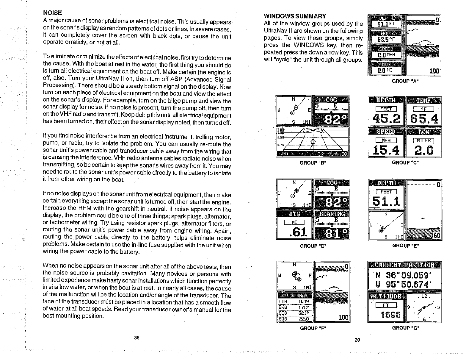
NOIISE
A
on the
it can
operate erraticly,
To eliminate or
the cause. With
is turn all electrical
off,
Processing).
turn on each
on the
sonar
on the
has been turned
If
pump,
sonar unit's
is
transmitting,
need to
it from other
If no noise
certain
Increase
display,
or
routing
routing
problems.
wiring
cause of sonar
major
sonar's
completely
also. Turn
sonar's
display
VHF radio and
find noise
you
or
radio, try
power
causing
tachometer
the interference. VHF
route the sonar
wiring
displays
everything except
the RPM with the
the
problem
the sonar
the
power
Make certain
the
power
display
minimize the effects of
the boat at rest in
your
There should
piece
display.
for noise. If
on,
interference from an
so be certain to
wiring. Try
problems
as
random
cover
the screen with
or
not at all.
equipment
UltraNay II
of electrical
For
transmit.
their
to isolate the
cable and
on
the boat.
on
the sonar
could
unjt's
cable
cable to the
on the
be a
example,
no noise is
Keep doing
effect on the sonar
transducer cable
keep
unit's
power
the sonar
gearshift
be one of three
using
power
directly
to use the in-line fuse
battery.
is electrical
patterns
electrical
the
water,
boat off. Make
then turn off ASP
on,
steady
equipment
turn on the
present,
electrical
problem.
radio antenna cables radiate
the sonar's wires
cable
unit from electrical
unit is turned
in neutral. If noise
resistor
cable
to the
noise. This
of dots or lines. In severe
black
dots,
noise, firsttryto
the first
bottom
away
signal
on the
boat and view the
bilge pump
turn
this until all
display noted,
instrument, trolling motor,
You can
away
directly
off,
things; spark
spark plugs,
from
battery
supplied
usually
or
thing you
certain the
(Advanced Signal
on the
the
pump
electrical
usually
from the
awayfrom
to the
battery
equipment,
then
starithe
appears
plugs,
alternator
engine
eliminate noise
helps
with the unit
appears
cases,
cause the unit
determine
should do
engine
display.
and view the
then
off,
equipment
then turned
re-route the
wiring
noise when
it. You
to isolate
then make
alternator,
filters,
wiring. Again,
is
Now
effect
turn
off.
that
may
engine.
on the
or
when
WINDOWS SUMMARY
All of the window
UltraNav II are shown on the
pages.
press
peated press
will
To view these
the WINDOWS
"cycle'
the unit
H
groups
the down arrow
.
1NI
used
groups,
key,
through
5 E
:.S
all
/
GROUP "B"
H
d
W E
•
S dM1
i)1
Ph
.61
€oie
5 E
,,,,,iI,,,,nñ,,uuI,,m, ñ
,,,,,. r,,,,,,i ,,,,,,l,,,,,, n
ti
GROUP " 0"
the
by
following
simply
then re-
This
key.
groups.
GROUP "A"
NON'ad:p
I FEET I
45.2
awjssi
I MPH I
15.4
GROUP "C"
I FEET I
51.1
H
fliI
I
65,4
It'IILESI
2.0
I
When no noise
the noise
limited
in shallow
of the malfunction will
face of the
of water at all
best
experience
mounting position.
appears
source is
water,
transducer must be
probably
make
or when the boat is
boat
speeds.
on the sonar
cavitation.
sonar
hasty
be the location
placed
Read
your
38
unit after all of the above
novices or
Many
installations which fUhotion
at rest. In
and/or
angle
in
a location that has a
transducer owner's manual for
all
nearly
of the transducer.
persons
cases,
smooth flow
tests,
perfectly
the
then
with
cause
The
the
H
E
1MI
.2
—
DIG 0.09
BRG 170°
QQ?.
BOG
3210
GROUP"F"
100
N
36°09.059'
U
95°50.674'
-
.
39
GROUP"G"
PDF compression, OCR, web-optimization with CVISION's PdfCompressor
 Loading...