

Page 1
Ultra Na vGPS
INSTALLATION AND OPERATION
INSTRUCTIONS
LITHO IN U.S.A. 988O1 06-61
PDF compression, OCR, web-optimization with CVISION's PdfCompressor
EAGI
F:1
TM
Page 2
NOTES:
Copyright © 1991, Eagle
WARNING!
Electronics. All
rights
reserved.
USE THIS GPS RECEIVER ONLY AS AN AID TO NAVIGATION.
CAREFUL NAVIGATOR NEVER RELIES ON ONLY ONE METHOD TO
OBTAIN POSITION INFORMATION.
CAUTION
This
GPS receiver,
shortest,
waypoint regardless
not
a
waypoint,
to the
As of this
GPS
phase.
the
receiver is
most direct
take
only
advantage
but will also
writing,
is
always
the
waypoint
navigation system
Satellites can be turned off or
system operators.
as accurate as the
only
all GPS
(like
to a
path
of obstructions.
navigation equipment)
waypoint.
Therefore,
of all available
visually
Department
as
Remember that the
check to make certain a
available.
NOTICE!
of Defense
operational.
system
It
provides navigation
the
navigation
The
accuracy
tools when
(DOD)
system
can be
UitraNavGPS,
it's
using.
will show the
data to the
prudent navigatorwill
travelling
clear,
safe
to
path
has not declared the
in
is still
degraded
or
a
testing
at
any
will
GPS
by
A
Features and
All
display
screens in this manual are simulated.
specifications
subject
to
change
without notice.
PDF compression, OCR, web-optimization with CVISION's PdfCompressor
Page 3
NOTES:
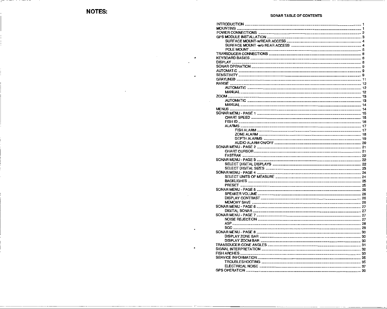
SONAR TABLE OF CONTENTS
INTRODUCTION
MOUNTING .
POWER CONNECTIONS .2
GPS MODULE
SURFACE MOUNT-w/REAR ACCESS 4
SURFACE MOUNT /o REAR ACCESS 4
POLE MOUNT 5
TRANSDUCER CONNECTIONS 6
KEYBOARD BASICS 6
DISPLAY
SONAR OPERATION 9
AUTOMATIC
SENSITIVITY 9
GRAYLINBTh 11
RANGE
AUTOMATIC 12
MANUAL 12
ZOOM 13
AUTOMATIC
MANUAL 14
MENUS 14
SONAR MENU-PAGE 1
CI-IARTSPEEO 15
FISHID 16
ALARMS 17
SONAR MENU - PAGE 2 21
CHART CURSOR 21
FASTRAK 22
SOKARMENU-PAGE3 22
SELECT DIGITAL DISPLAYS 22
SELECT DIGITAL SIZES
SONAR MENU
SELECT UNITS OF MEASURE 24
BACKLIGHTS 25
PRESET 25
SONAR MENU - PAGE 5 26
SPEAKER VOLUME 26
DISPLAY CONTMST 26
MEMORY SAVE 26
SONAR MENU - PAGE 6 27
DIGITAL SONAR
SONAR
NOISE REJECTION 27
ASP
SCC 29
SONAR MENU
DISPLAY ZONE BAR 30
DISPLAY ZOOM BAR 30
TRANSDUCER CONE ANGLES SI
SIGNAL INTERPRETATION 32
FISH ARCHES
SERVICE INFORMATION 35
TROUBLESHOOTING 35
ELECTRICAL NOISE 37
GPS OPERATION 39
.
INSTALLATION 3
8
9
12
13
15
FISH ALARM 17
ZONEALARM ID
DEPTH ALARMS
AUDIO ALARM ON/OFF 20
-
PAGE 4 24
MENU - PAGE 7 27
-
8
PAGE
19
23
27
28
30
33
PDF compression, OCR, web-optimization with CVISION's PdfCompressor
Page 4

NOTES:
PDF compression, OCR, web-optimization with CVISION's PdfCompressor
Page 5
NOTES:
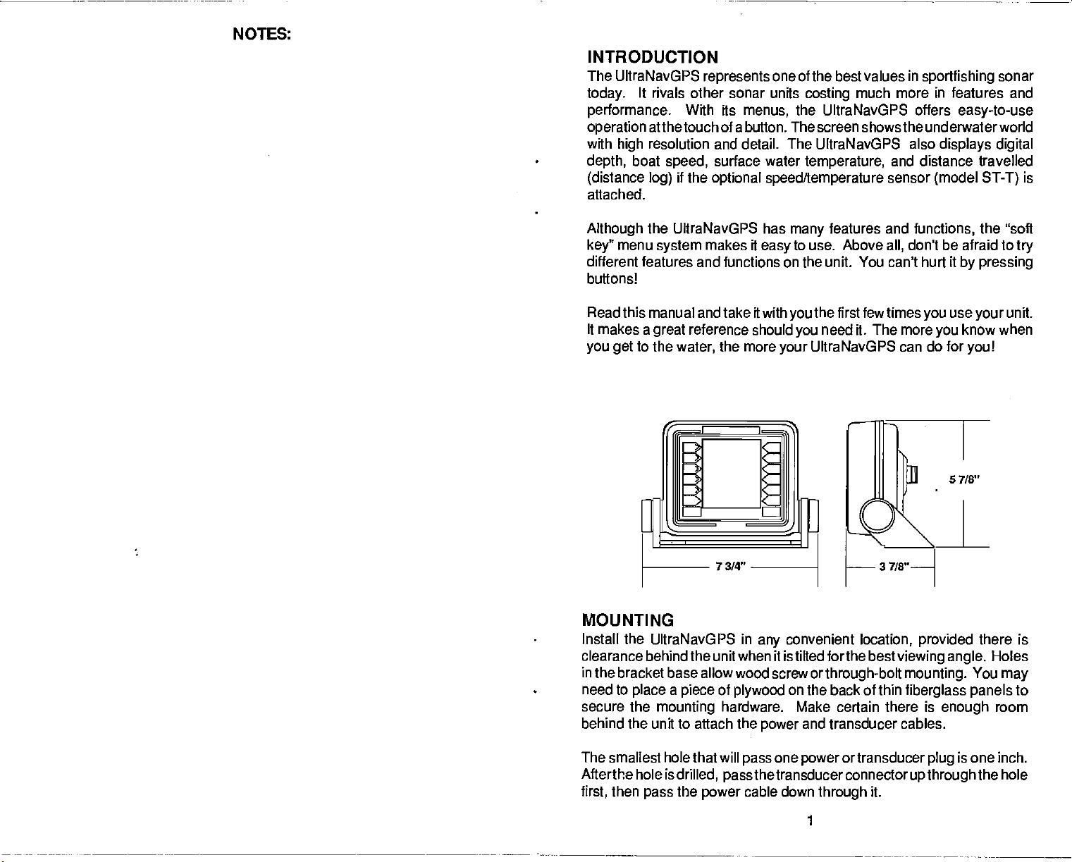
INTRODUCTION
The
UltraNavGPS
today.
performance.
operation
with
depth,
(distance
attached.
It rivals other sonar units
atthetouch of a button. The screen shows the underwaterworld
resolution and detail. The UltraNavGPS also
high
boat
log)
With its
speed,
if
the
represents
one of the best values
menus,
surface water
optional
speed/temperature
in
sportlishing
costing
much more in features and
the UltraNavGPS offers
displays digital
temperature,
and distance travelled
sensor
(model
sonar
easy-to-use
is
ST-T)
Although
key"
different features and
buttons!
the UltraNavGPS has
menu
system
makes it
easy
functions on the unit. You can't
Read this manual and take it with
It makes a
you get
to the
reference should
great
the more
water,
your
features and
many
to use. Above
first few times
the
you
need it. The more
you
UItraNavGPS can do for
all,
MOUNTING
Install the UltraNIavGPS in
clearance behind the unit when it is tilted forthe best
in
the bracket base allow wood screw
need to
secure the
behind the unit to attach the
place a piece
mounting
of
plywood
hardware. Make certain there is
convenient
any
orthrough-bolt mounting.
on the back of thin
and transducer cables.
power
location,
functions,
the "soft
don't be afraid to
hurt it
by pressing
use
you
your
know when
you
you!
provided
viewing angle.
there is
You
fiberglass panels
enough
try
unit.
Holes
may
to
room
The smallest hole that will
Afterthe hole is
then
first,
pass
drilled,
the
power
passthe
pass
one
power
ortransducer
transducerconnector
cable down
through
1
upthroughthe
it.
plug
is one inch.
hole
PDF compression, OCR, web-optimization with CVISION's PdfCompressor
Page 6
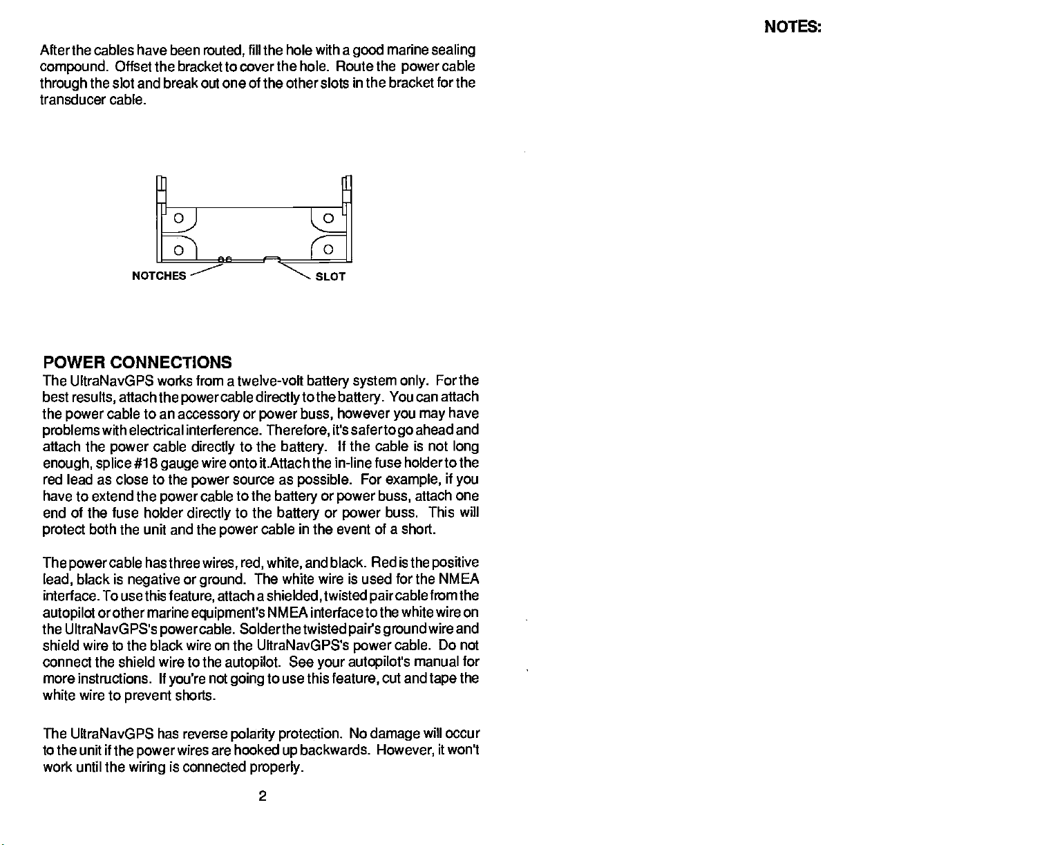
After the cables have been
compound.
through
Offset the bracket to cover the hole. Route the
the slot and break out one of the other slots
transducer cable.
routed,
fill the hole with a
marine
good
in the bracket for the
sealing
power
cable
NOTES:
o
0
NOTCHES
o
0
SLOT
POWER CONNECTIONS
The tJltraNavGPS works from a twelve-volt
best
results,
the
power
problems
attach the
enough, splice
red lead as close to
have
to extend the
end of the fuse holder
protect
The
powercable
black is
lead,
interface. To usethis
autopilot
the UltraNavGPS's
attach the
cable to an
accessory
power
cable
with electrical interference.
#18
cable
gauge
the
power
directly
wire onto it.Attach the in-line fuse
power
cable
power
directly
both
the unit and the
hasthree
negative
feature,
orother marine
powercable.
power
wires, red, white,
or
ground.
attach a
equipment's
directlyto
or
power
to the
source as
to the
to the
cable in the event of a short.
The
Solderthetwisted
shield wire to the black wire on the UltraNavGPS's
connect the shield wire to the
more
instructions.
white wire to
If
prevent
you're
shorts.
autopilot.
not
going
battery system only.
the
battery.
however
buss,
Therefore,
battery.
battery
battery
it's
If the cable is not
possible.
or
power
or
power
and black. Red is the
wire is used for the NMEA
white
shielded,
twisted
NMEA interface tothe white wire on
See
your autopilot's
to use this
feature,
You can attach
you may
safertogo
ahead and
holderto the
For
example,
attach one
buss,
buss. This will
paircable
pairs ground
cable. Do not
power
manual for
cut and
For the
have
long
if
you
positive
fromthe
wire and
the
tape
The UltraNavGPS has reverse
to the unit if the
work until the
wiring
power
is connected
wires are hooked
polarity protection.
backwards.
up
properly.
2
No
damage
However,
will
occur
it won't
PDF compression, OCR, web-optimization with CVISION's PdfCompressor
Page 7
NOTES:
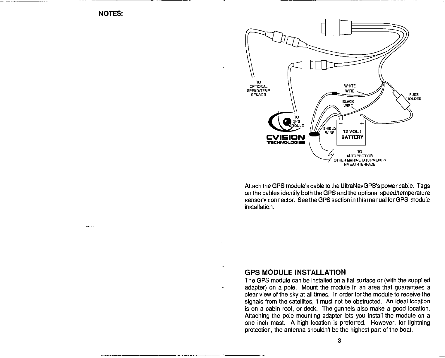
TO
OPTIONAL
SPEED/TEMP
SENSOR
TO
OPS
MODULE
TO
AUTOPILOT OR
OTHER MARINE EQUIPMENTS
NMEA INTERFACE
FUSE
Attach the GPS module's cable to the UltraNavGPS's
on the cables
identify
both the GPS and the
optional speed/temperature
power
cable.
Tags
sensors connector. See the GPS section in this manual for GPS module
installation.
GPS MODULE INSTALLATION
The GPS module can be installed on a flat surface or
adapter)
on a
clear view of the
signals
is on a cabin
Attaching
from the
roof,
the
pole mounting adapter
one inch mast. A
protection,
the antenna shouldn't be
Mount the module in an area that
pole.
at all times. In order for the module to receive the
sky
satellites,
or deck. The
high
it must not be obstructed. An ideal location
gunnels
location is
also make a
lets
you
preferred.
the
highest part
install the module on a
However,
3
the
(with
supplied
guarantees
location.
good
for
lightning
of the boat.
a
PDF compression, OCR, web-optimization with CVISION's PdfCompressor
Page 8
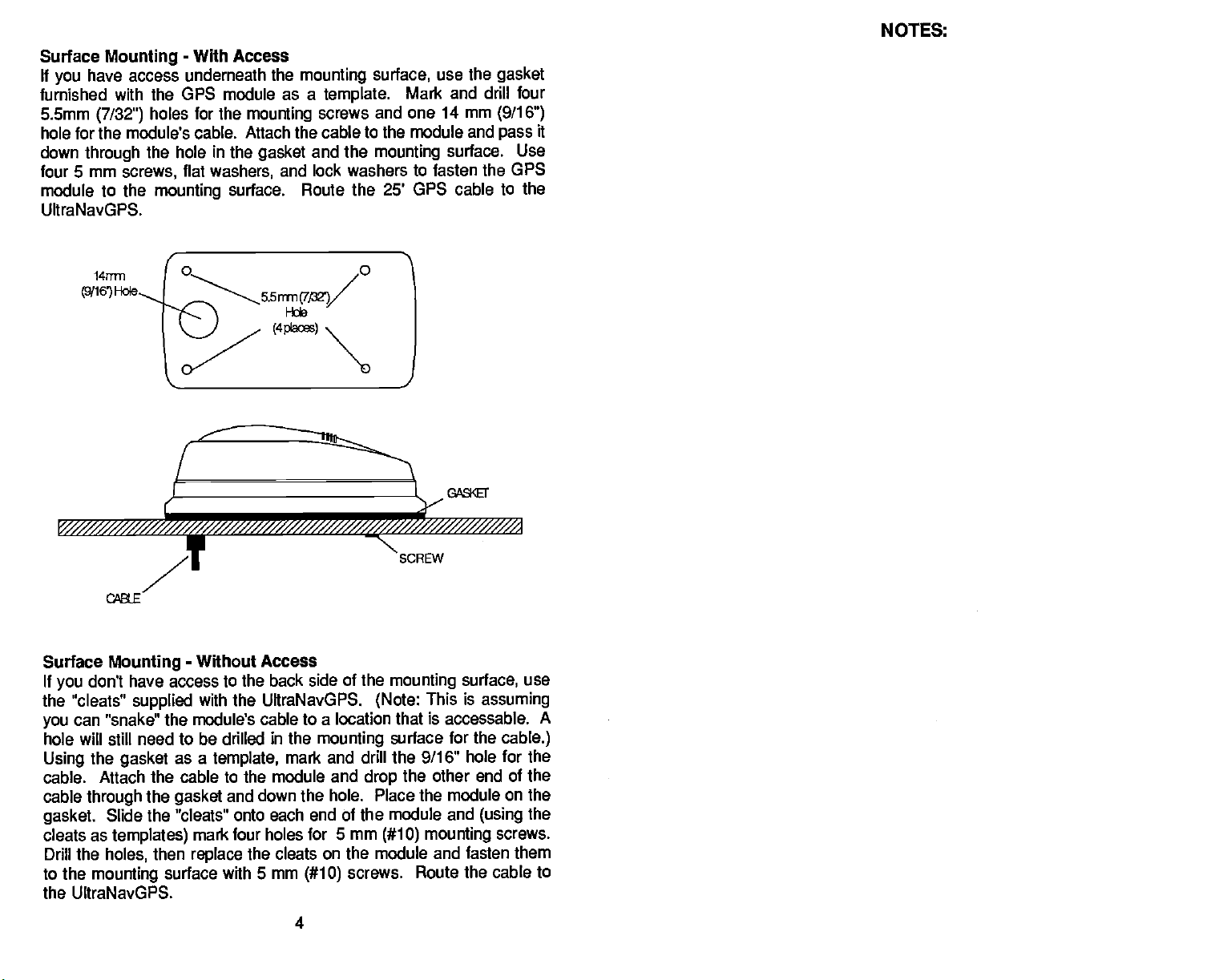
Surface
If
you
furnished with the GPS
5.5mm
hole for the module's cable.
down
four 5 mm
module to the
UltraNavGPS.
Mounting
have access underneath
(7/32")
through
screws,
-
With Access
module as a
holes for the
the hole
mounting
in
flat
washers,
7
the
mounting
template.
mounting
Attach the cable to the module and
the
gasket
surface. Route the 25' GPS cable to
screws and one 14 mm
and the
lock washers to fasten the OPS
and
surface,
mounting
use the
Mark and drill four
surface. Use
gasket
(9/16")
pass
NOTES:
it
the
y///////////////////
Surface
If
don't have access to the back side of the
you
the "cleats"
can "snake" the
you
will
hole
the
Using
cable. Attach
cable
through
gasket.
cleats as
Drill
the
to the
the UltraNavGPS.
mounting
I
/////////////////////////////////////////A
-
Mounting
supplied
need to be drilled in the
still
gasket
the
Slide the "cleats" onto each end of the module and
templates)
holes,
Without Access
with the UltraNavGPS.
module's cable to a location that is accessable.
mounting
a
as
template,
the cable to the module and
gasket
then
surface with 5 mm
and down the hole. Place the module
mark four holes for 5 mm
replace
mark and drill the 9/16" hole for the
the cleats on the module and fasten them
screws. Route the
(#10)
4
SCREW
mounting
(Note:
drop
This is
surface for the
other end of the
the
(#10) mounting
surface,
use
assuming
cable.)
on the
the
(using
screws.
cable to
A
PDF compression, OCR, web-optimization with CVISION's PdfCompressor
Page 9
ULTRANAVGPS SONAR
UItraNavGPS Dimensions 5.875"H x 7.75"W x 3.875"D
Input Voltage
Current
Transmitter
Display
Pixels
Frequency
Output
Size
Power
(typical)
SPECIFICATIONS
10-15 vDO
500 ma
650 ma
192 kHz
600 watts
75 watts
3.1"H x 2.4"W
128 H x 80W
10,240
(lights off)
(lights on)
(peak-to-peak)
(RMS)
Total
fl,o
"\ Myl<ANDmtL/"
FOLJRRAES
__
I I-
ULTRANAVGPS GPS RECEIVER SPECIFICATIONS
GPS Module Dimensions 2.5"H x 4.1W x 7" D
Channels Five Parallel
Four continuous for
All
satellites
Update
Accuracy
Position: 25 meters CEP
Velocity:
NMEA
rate One second
Maximum
Standard
0.25 meters/sec RMS
Without SA PDOP.c6.0
0183 SENTENCES
RMB Minimum Recommended
RMC Minimum Recommended
GLL Present Position
APA
DBK Water
MTW Water
VHW
VLW Distance Travelled/LOG
Autopilot Steering
Depth
Temperature (oC)
Speed Through
-
Latitude/Longitude
Data
Water
in
accuracy
Positioning
Sentence,
Sentence,
(MPH)
(NM)
position
view tracked
achievable with
Service
Part B
Part C
— sa
rr
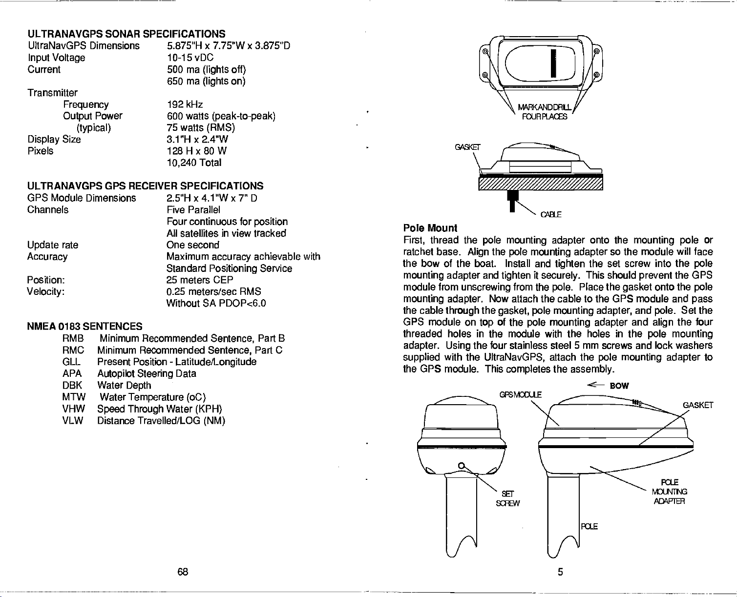
Pole Mount
thread the
First,
ratchet base.
the bow of the boat. Install and
mounting adapter
module fitm
mounting
the cable
GPS
threaded holes in the module with the holes in the
adapter. Using
supplied
the GPS module. This
adapter.
through
module on
with the
pole mounting adapter
the
Align
unscrewing
the four stainless steel 5 mm screws and lock washers
pole mounting adapter
tighten
and
tighten
Now attach the cable to the GPS module and
the
gasket, pole mounting adapter,
of the
top
UltraNavGPS,
it
securely.
from the
completes
pole.
pole mounting adapter
attach the
the
I I
( '•l
onto the
mounting pole
so the module will face
the set screw into the
This should
Place the
assembly.
gasket
and
and
pole mounting adapter
BOW
TAsKET
prevent
the GPS
onto the
Set the
pole.
the four
align
pole mounting
or
pole
pole
pass
to
PDF compression, OCR, web-optimization with CVISION's PdfCompressor
68 5
Page 10
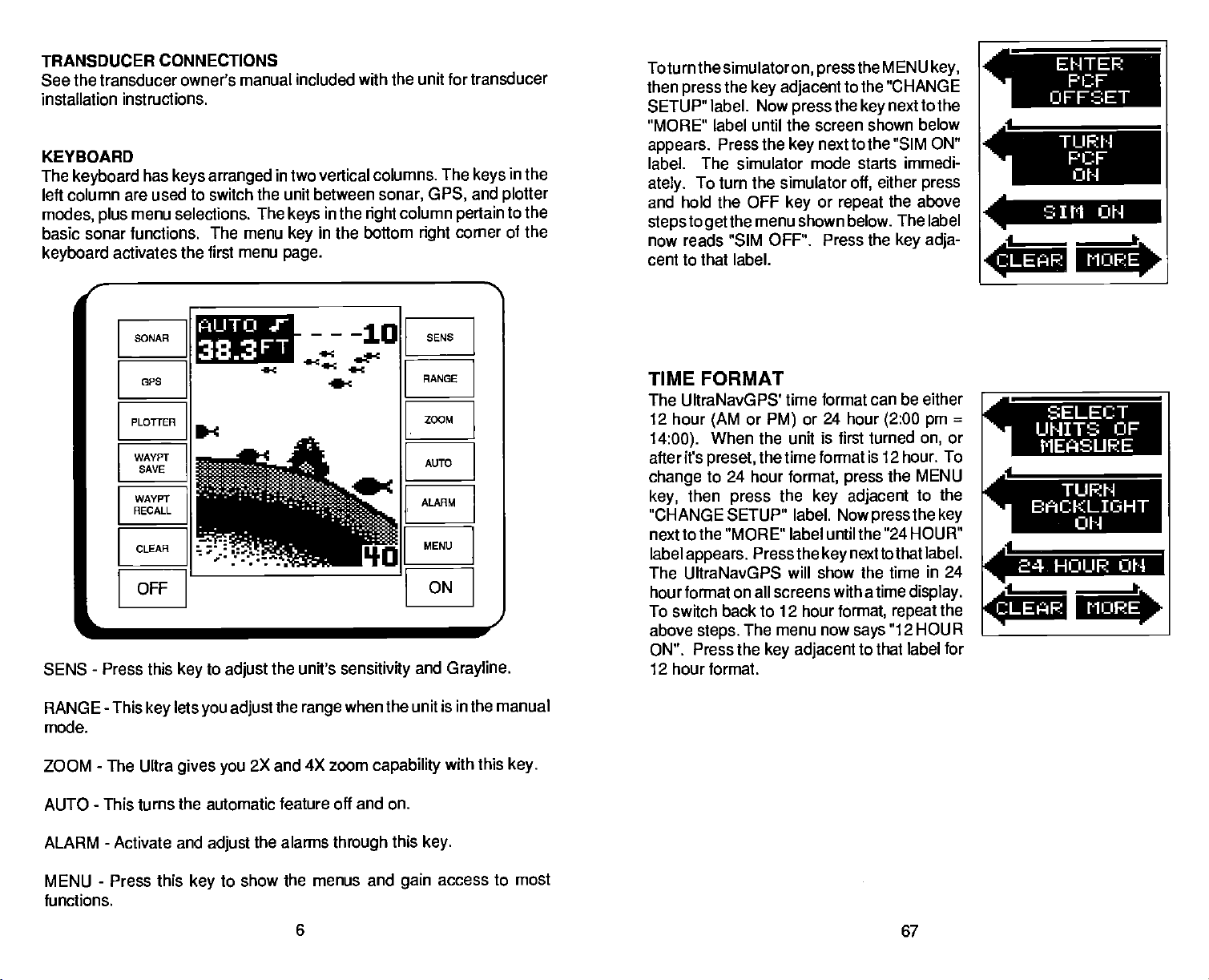
TRANSDUCER
See the transducer owner's manual
installation instructions.
KEYBOARD
The
keyboard
left column are used to switch the unit between
modes, plus
basic sonar functions. The menu
keyboard
CONNECTIONS
has
keys arranged
menu selections. The
activates the first menu
included with the unit for transducer
in two vertical columns. The
in the
keys
in the bottom
key
page.
sonar, GPS,
column
right
right
keys
and
pertain
corner
in the
plotter
to the
of the
Toturnthesimulatoron,
then
SETUP" label. Now
'MORE" label until the screen shown
appears.
label. The simulator mode starts
ately.
and hold the OFF
stepstogetthemenu
now reads "SIM
cent to that label.
the
press
To turn the simulator
key adjacent
Press the
pressthe
press
next to the
key
or
key
shown below. The label
OFF". Press the
MENU
to the "CHANGE
the
repeat
key
off,
next to the
"SIM ON"
immedi-
either
the
key adja-
key,
below
press
above
.4
.1
C L E ' F:
ENTER
F' CF
OFFSET
I
SIM OH
I.
F1 ORE
SONAR
GE'S
PLOTTER
WAVEr
SAVE
WAVPT
RECALL
CLEAR
OFF
L
SENS - Press this
RANGE - This
mode.
ZOOM
-
key
The Ultra
flLlTO .r
38.3
to
key
adjust
lets
you adjust
gives you
----10
FT
2X and 4X zoom
-C
-C
the unit's
the
range
-C
sensitivity
when the unit is in the manual
SENS
RANGE
ZOOM
AUTO
ALARM
MENU
ON
and
capability
-I
Grayline.
with this
key.
TIME FORMAT
The UltraNavGPS' time format can be either
12 hour
14:00).
after it's
change
then
key,
"CHANGE SETUP" label.
next to the "MORE' label until the
label
appears.
The UitraNavGPS will show the time
hou rformat on all screens with a time
To switch back to 12 hour
above
steps.
ON". Press the
12 hour format.
or
(AM
When the unit is first turned
preset,
to 24 hour
press
The menu now
or 24 hour
PM)
the time format is 12 hour. To
format,
the
key
Press the
key adjacent
key
(2:00 pm
the
press
adjacent
Nowpressthe
"24 HOUR"
next tothat label.
format, repeat
"12 HOUR
says
to that label for
=
or
on,
MENU
the
to
key
in 24
display.
the
SELECT
UNITS OF
MEflSUF'.E
4
TURN
BACKLI'3HT
OH
____
1
e_
F11JRE
AUTO - This turns the automatic feature off and on.
ALARM
MENU - Press this
functions.
-
Activate and
the alarms
adjust
to show the menus and
key
6
through
this
key.
access to most
gain
67
PDF compression, OCR, web-optimization with CVISION's PdfCompressor
Page 11
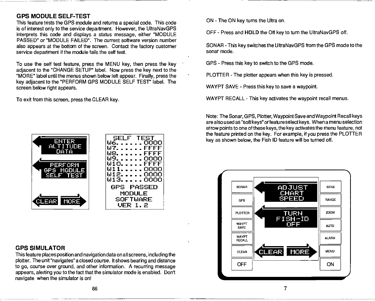
GPS MODULE SELF-TEST
This feature tests the GPS module and returns a
is of interest
interprets
this code and
PASSED" or "MODULE FAILED". The
also
appears
service
department
To use the self test
adjacent
to the 'CHANGE SETUP" label. Now
"MORE" label until the menus shown below left
key adjacent
screen below
To
exit
from
to the service
only
department.
displays
a status
However,
message,
current software version
at the bottom of the screen. Contact the
if the module fails the self test.
feature,
press
the MENU
appear. Finally, press
to the "PERFORM GPS MODULE SELF TEST' label. The
right appears.
this
screen,
press
the CLEAR
key.
special
then
key,
press
code. This code
the UltraNavGPS
either "MODULE
number
press
next to the
key
customer
the
factory
the
key
the
-
ON
The ON
-
OFF
Press and HOLD the Off
SONAR - This
sonar mode.
-
GPS
PLOTTER
WAYPT
WAYPT
Press this
-
The
SAVE - Press this
RECALL
turns the Ultra on.
key
to turn the UltraNavGPS
key
switches the UltraNJavGPS from the
key
to switch to the GPS mode.
key
plotter appears
-
This
key
when this
to save a
key
activates
key
waypoint.
the
waypoint
GPS mode to the
is
pressed.
recall menus.
off.
EHTER
flLTITUDE
DATA
4
PERFORM
15PS MODULE
SELF TEST
CLEAR MORE
GPS SIMULATOR
This feature
plotter.
to
go,
appears, alerting
navigate
places position
The unit
"navigates"
course over
you
when the
ground,
simulator is on!
and
navigation
a closed course. It shows
and other information. A
to the fact that the
simulator mode is enabled. Don't
SELF TEST
t'J6 0000
147 FFFF
148 FFFF
149 0000
kilO
FFFF
kill 0000
1412 0000
1413 0000
UPS PASSED
MODULE
SOFTWARE
VER 1. 2
data on all
screens,
bearing
including
and distance
recurring message
the
Note: The
Sonar,
G
PS, Plotter, Waypoint
are also used as "soft
arrow
the feature
as shown
key
to one of these
points
printed
on the
below,
r
____________________________________________________________
SONAR SENS
GPS
PLOTrER
WAYPT
SAVE
WAYPT
RECALL
CLEAR
OFF ON
L
Save and
orfeature select
keys"
the
keys,
key.
For
example,
key
the Fish ID feature
I
activates
will
When a
keys.
if
you press
be turned
ADJUST
CHART
SPEED
___________________
FISH—ID
___________________________
________________________________
.4
CLEAR MORE
OFF
Waypoint
menu
the menu
the
off.
____________________________________________________________
RANGE
ZOOM
AUTO
ALARM
I
MENU
Recall
keys
selection
feature,
PLOTTER
I
I
not
PDF compression, OCR, web-optimization with CVISION's PdfCompressor
66
7
Page 12
ALITO ,F
I}53FT
I
METRICI
)
<ONEiJI
<ADJI
ONI
LIt
OISP
0
4C
LAVI
SELECT UNITS OF MEASURE
TURN BACKLIGHT ON
SET SPEAKER VOLUME
ADJUST DISPLAY CONTRAST
These menus are
sonar section for more information on these features.
duplicates
of the ones found in the sonar menus. See
MAN OVERBOARD
One of
fall overboard. This situation can be
salt. It's
course,
measures to
can use the UltraNavGPSto initiate a search
boating's
particularly dangerous
the first
most
terrifying
to do is remain calm and
thing
and rescue the
try
events is
deadly
at
night
person.
having
if
or
If
you
a friend or
on
any body
you're
lose
pattern.
out
try
sight
family
of
water,
of
sight
of land. Of
all standard
of the
person, you
the
member
fresh or
safety
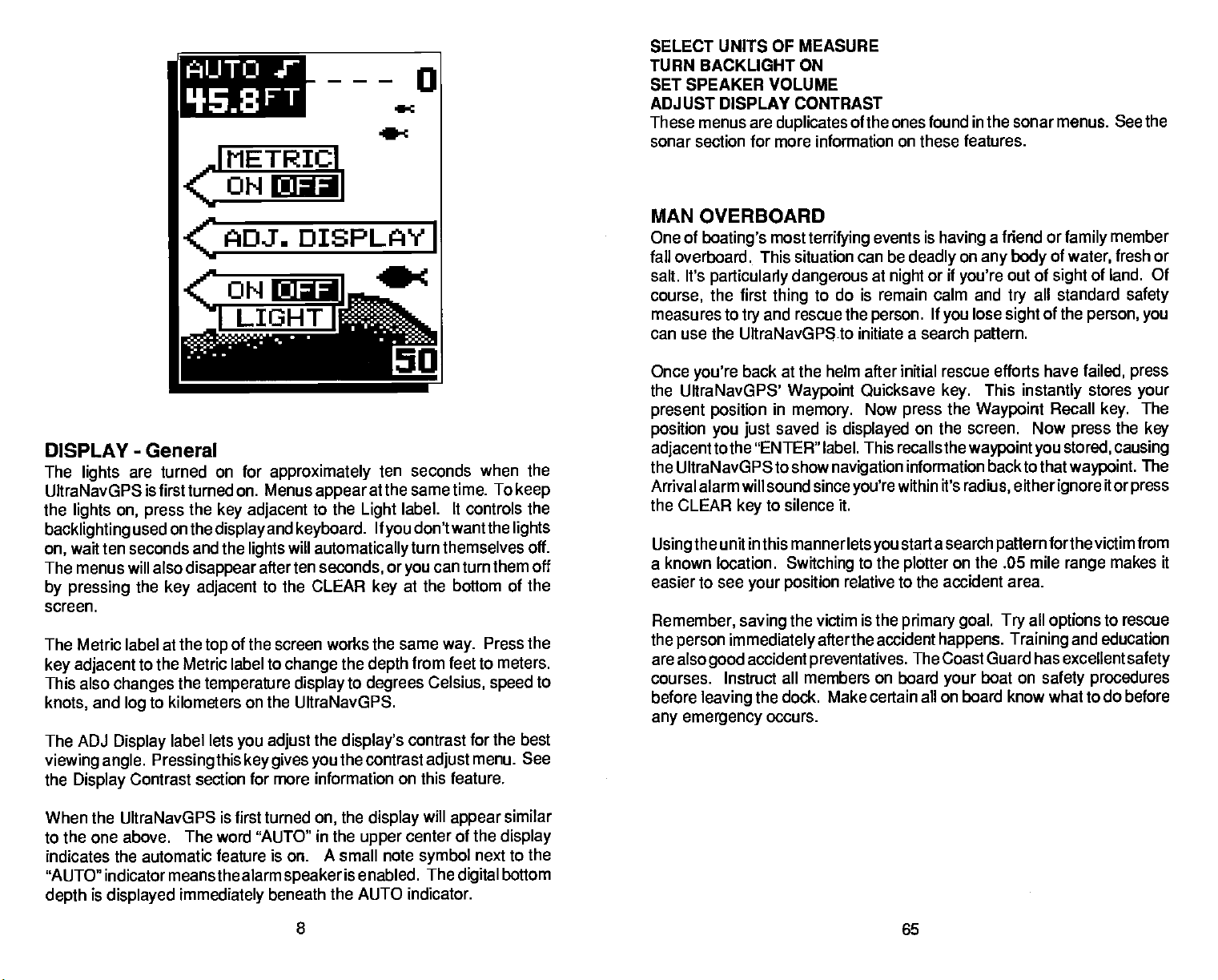
DISPLAY
The
lights
UltraNavGPS
the
lights on, press
backlighting
wait ten seconds and the
on,
The menus will also
by pressing
screen.
The Metric label at the
key adjacent
This also
knots,
The ADJ
viewing angle. Pressing
the
Display
When the UltraNavGPS
to the one above. The word "AUTO"
indicates the automatic
"AUTO" indicator means the alarm
depth
-
General
are turned on for
is first turned on. Menus
the
key adjacent
used on the
the
key adjacent
display
disappear
top
to the Metric label to
changes
and
log
Display
is
displayed
the
temperature
to kilometers
label lets
this
Contrast section for more
is first turned
feature is on. A small note
immediately
approximately
and
keyboard.
will
lights
after ten seconds,
to the CLEAR
of the screen works the same
change
display
on the UltraNavGPs.
you adjust
key gives you
speaker
beneath
seconds when the
ten
appear
to the
automatically
the
information on this feature.
on,
in the
at the same time. To
label, It controls the
Light
If
don't want the
you
turn themselves off.
or
can turn them off
you
at the bottom of the
key
way.
the
to
display's
the contrast
the
upper
is enabled. The
the AUTO indicator.
from feet to meters.
depth
degrees
display
Celsius,
contrast for the best
adjust
will
appear
center of the
symbol
digital
Press the
speed
menu. See
next to the
keep
lights
to
similar
display
bottom
Once
you're
the UUraNavGPS'
present position
position you just
adjacenttothe
the UltraNavGPS to show
Arrival alarm will sound since
the CLEAR
Using
a known location.
easier to see
Remember, saving
the
person
are also
courses. Instruct all
before
emergency
any
back at the helm after initial rescue efforts have
Waypoint
in
memory.
saved is
"ENTER" label. This recalls
navigation
to silence it.
key
the unit in this manner lets
Switching
your position
the victim is the
immediately
accident
good
leaving
the dock.
occurs.
afterthe accident
preventatives.
members on board
Make certain all on board know what to do before
Quicksave
Now
press
displayed
you're
to the
relative to the accident area.
on the screen. Now
information backto that
within it's
start asearch
you
plotter
primary goal. Try
The Coast Guard has excellent
This
key.
the
thewaypointyou
radius, eitherignore
on
instantly
Waypoint
pattern
.05 mile
the
all
happens. Training
boat on
your
failed,
press
stores
your
Recall
press
stored, causing
waypoint.
forthevictim
range
options
and education
safety procedures
The
key.
the
key
The
itor
press
from
makes it
to rescue
safety
8
65
PDF compression, OCR, web-optimization with CVISION's PdfCompressor
Page 13

NMEA COMMUNICATION
The UItraNavGPS
according
Association).
to send
mation to "listener'
instruments, autopilots,
instruments.
following
and 0183.
mation
NMEAO183 sends
speed,
feature,
to standanis
position,
NMEAdata
NMEAO18O sends
only.
and
the white
must be connected to the
other instrument. See the installation
on the
section
information.
Oncethe
in this manual for
wiring
data format to use. Consult the owner's
to see which format it needs. Then set the UltraNavGPS
First, press
press
tothe"More" label untilthe "SELECTNMEAOUTPUT"
the
key
The data lormat
key adjacent
last used GPS or
the
power
the MENU
the
key
next to this label. The screen
cable.
sends data out the white wire on the
set
allows the UltraNavGPS
This
and
depth,
units,
and other marine
the NMEA
by
navigation
such as
infor-
charting
The UltraNavGPS uses the
protocols:
Its useful
more. In order to use this
mainly
depth, position, steering,
wire on the
is connected
key
next tothe
"Change Setup"
currently
to the desired data
screen,
plotter
NMEA 0180
steering
for
power
NMEA data
wiring
properly,
while a
intor-
autopilots.
cable
input
connection
the UltraNavGPS must be told which
manual of the "listener"
GPS or
label. Now
shown above
in use shows at
output.
and send NMEA data out the white
The UltraNavGPS will return
(National
_____________________
Marine
OUTPUT
Select
SELECTION SCREEN
NMEA
the
screen is
press
label
appears.
of the screen. Press the
top
plotter
power
Electronics
IS:
OFF
equipment
as follows:
displayed.
the
key
appears.
cable
Next,
adjacent
Press
to the
wire on
SONAR OPERATION
AUTOMATIC
When .the UltraNavGPS
enabled. This is indicated
The Automatic feature
is
signal
displayed
To turn Automatic
appears, indicating
AUTO
the
press
AUTOMATIC
MODE ON
in the lower half of the screen at all
off, simply press
the unit is in the manual
key again.
is first turned
the word "AUTO" at the
by
adjusts
JALJTO
38.3FT
the
J
4<
on,
sensitivity
AUTO
the
mode. To turn Automatic
-C
4<4<
4<
ec
the Automatic
of
top
and
key.
so the bottom
range
times.
The letters "Man"
feature is
the screen.
on,
SENSITIVITY
The
PRESET
The Preset feature returns all sonar and
settings.
mode on the sonar
waypoints
To
preset
appears.
and the UltraNavOPS
returned to their
This resets the units of
or
routes,
the
unit,
Press the
side,
display
however.
press
key adjacentto
returns to the GPS
contrast,
the
MENU key
factory settings.
PDF compression, OCR, web-optimization with CVISION's PdfCompressor
GPS units to their
measure, speaker
volume,
and more. This doesn't erase
until the "PRESET UNIT" label
label. The menu screen
that
position
64
screen. All units
original
automatic
disappears
factory
any
will be
sensitivity key
pick up
information,
echoes. A low
levels enables
noise.
signal
When the UltraNavGPS is in the Automatic
automatically adjusted
more. This
Typically,
with
Grayline
gives
on the UltraNavGPS
sensitivity
fish
signals,
to see this
you
the best
and some surface
to
keep
it the
capability
and other
detail,
sensitivity
a solid bottom
controls the
level excludes
information.
target
it can also clutter the screen with
but
shows a
level
clutter.
to show fish and
much of the bottom
mode,
displayed, plus
signal
other detail.
9
of the unit to
ability
High sensitivity
solid bottom
good
the
sensitivity
is
a little
Page 14
However,
decrease the
more
adjust
To
adjust
appears
menu is
The
The
above the
situations occur
so
detail,
it is the same whetherthe unit is in the
the
on the left side of the screen. The switch forthe
immediately
sensitivity
graph gives
up
q3•3rT
where it becomes
sensitivity.
an
increase
sensitivity, press
menu has
a visual indication of
arrow also shows the
This
in
beneath
up
typically happens
sensitivity
the SENS
it.
and
___________ For
-20
ec
e
04
GRAY
down
percentage
I
U
necessary
when
is indicated. The
automatic or manual mode.
The
key.
arrows,
the
sensitivity
sensitivity adjust
plus
of
sensitivity
to increase or
you
Grayline adjust
a vertical bar
level. The number
wish to see
procedure
menu
graph.
in use.
to
example, suppose you
marked on
.010
Factor
the
chart.
change you
datum used
entering
the unit is turned off.
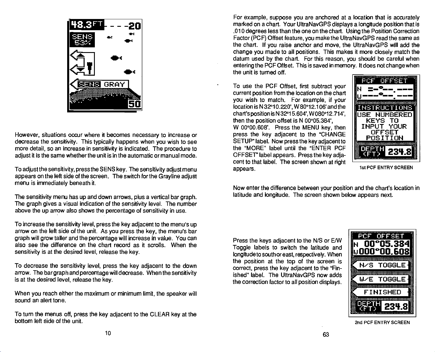
To use the PCF
current
you
location is N 32°1
chart's
then the
W 00°00.608'. Press the MENU
press
SETUP" label. Now
the "MORE" label until the "ENTER PCF
OFFSET" label
cent to that label. The screen shown at
appears.
Now enter the difference between
latitude and
a chart. Your UltraNavGPS
degrees
wish to match. For
less than the one on the chart.
Offset
(PCF)
If
made to all
by
the PCF Offset. This is saved in
position
position
position
the
key adjacent
longitude.
feature,
raise anchor and
you
the chart. For this
Offset,
from the location on the chart
0.220',
is N 32°1
offset is N
press
appears.
are anchored at a location that is
displays a longitude position
make the UltraNavGPS read the same as
you
the UltraNavGPS will add the
move,
positions.
first subtract
example,
W80°1 2.106' andthe
5.604',
00°05.384',
to the 'CHANGE
the
Press the
The screen shown below
This makes it more
reason,
memory.
your
if
your
W080°1
key adjacent
2.714',
then
key,
to
key adja-
right
your position
accurately
that is
the Position Correction
Using
closely
should be careful when
you
It does not
match the
change
when
•aa.iaa
— 0_ —
N
U———0——.
JSE NUMBERED
KEYS TO
INPUT YOUR
OFFSET
POSITION
—— —
-
r
itt PCF ENTRY SCREEN
and the chart's location in
appears
next.
To increase the
arrow on the left side of the unit. As
will
graph
also see the difference on the chart record as it scrolls. When the
sensitivity
To decrease the
arrow. The
is at the desired
When
you
sound an alert tone.
To turn the menus
bottom left side of the unit.
sensitivity
taller and the
grow
is at the desired
sensitivity
bargraph
level,
reach either the maximum or minimum
off,
level,
percentage
level,
level,
and
percentage
release the
the
press
the
press
release the
press
key.
key adjacent
key adjacent
you press
will decrease. When the
the
will increase in value. You can
key.
the
key adjacent
to the CLEAR
10
to the menu's
the menu's bar
key,
the
limit,
up
to the down
sensitivity
key
will
at the
speaker
Press the
Toggle
longitudetosouthoreast, respectively.
the
correct,
ished" label. The UltraNavGPS now adds
the correction factor to all
keys adjacent
labels to switch the latitude and
press
at the
the
position
to the N/S or E/W
of the screen is
top
key adjacent
position displays.
When
to the "Fin-
63
N 00005334
LI000°0O.603
ra
N'S TOGGLE
W'E TOGGLE
-
FINISHED
2nd PCF ENTRY SCREEN
PDF compression, OCR, web-optimization with CVISION's PdfCompressor
Page 15

CHANGING STARTUP SETFINGS
The UItraNavGPS must be initialized when it's turned
This is described at the
if
However,
use the menu features in the "CHANGE SETUP"
the MENU
The screen shown
the menus on this and
Using
pages, you
Time-Date-Time
affecting any
these
described in the initialization section at the
sequence
want to enter a new initial
menus work
beginning
achange,
screen,
For
(over
UltraNavGPS find the correct
however. It doesn't
example,
100
wish to
you
then
key,
can
change
Offset,
other initialization
of the GPS section.
the unit
through
if
you
miles)
returnstotheGPSorplotter
with the unit
beginning
change only
the
press
below
key adjacent
appears.
following
the Initial
or Altitude without
identically
Afteryou
the initialization
move a
position
position quicker.
of the GPS section in this manual.
one of the
menu
Position,
setting.
All of ____________________
to the ones
make ____________________
automatically
menus.
distance
long
off,
you may
to
help
parameters (such
menu. To do
tothe "CHANGE SETU P" label.
______________________
_____________________
A
________ ________
the
on for the first time.
as
time),
this,
press
ENTER
INITIAL
POS IT ION
ENTER
TI P1 E/
DATE
N OR
GRAYLINE®
GRAYLINE lets
"paints" gray
to tell the difference between a hard and soft bottom.
you
a
soft,
muddy
with a narrow or no
causes a wide
If
have two
you
then the
weeds from trees on the
GRAYLINE® is
between
different GRAYLINE®
at
unit to find the
target
strong
poweron
you distinguish
on
targets
or
gray
signals
with
adjustable.
and weak
is
usually adequate
GRAYLINE®setting
that are
weedy
bottom returns
line. A hard bottom
gray
line.
of
equal
is the
gray
bottom,
signals,
level,
}9•3
_____
between
strongerthan a preset
strong
a weaker
returns a
one with
size,
stronger signal.
or fish from structure.
Since GRAYLINE®
adjusting
also. The level chosen
for most conditions.
that's
FT
---20
gray
the
sensitivity may require
best for
and weak echoes. It
value. This allows
For
example,
which is shown
signal
strong signal
and the other
This
helps
shows the difference
the UltraNavGPS
by
Experiment
you.
which
without,
distinguish
with
your
a
•4
jj
PCF OFFSET
(Position
The GPS
determine
is the Earth's
calculations
more
deviations are.
approximate
if
your navigation
one. The term used for these
To reduce the error factor between
capability
shown on the chart. The unit adds this offset to all
PDF compression, OCR, web-optimization with CVISION's PdfCompressor
Correction
navigation system
yourposition
shape.
have to be made to accommodate deviations. To make matters
complex,
not
everyone
The size and
the earth's surface are
device uses
to move or "offset" the
Factor)
on
relies
based on satellite data and otherfactors. One factor
Since the Earth is not a true
one
complex
uses the same data to determine what the
shape
improved
ellipsoid,
ellipsoids
datum,
position
62
mathematical calculations to
sphere,
of the
ellipsoids
often. This can lead to errors
while
is
your
"datum."
variations in the
that are used to
chart uses a different
the UltraNavGPS
shown on the
displayto
position displays.
gives you
match one
the
cRAvuNea—
To
adjust
appears
label
"SENS GRAY" label. This
GRAYLINE®
increase the
decrease it. The
keys
GRAYLINE® level. You can see
menu and on the chart
the
adjustmentr press
GRAYLINE
in the
appears immediately
adjust.
gray
are
pressed.
left side of the
upper
Now
level. Press the
percentage
The bar chart also
record)
the CLEAR
the SENS
press
beneath it. First
changes
press
of GRAYLIN
as
the
the
you
key
01
key.
display,
key adjacent
11
while
press
the
sensitivity adjust
key adjacent
E® in
a
gives
change
press
graphical
on the screen
the
to erase the
The
sensitivity
menu
the GRAYLlNEwitch
menu to
arrow
up
to the
the
key adjacent
to the
to the down arrow to
use
keys.
changes
menu.
as the arrow
indication of the
on the
(both
After
you've
made
to
Page 16

- •- S_S!_
flMflUC
When turned on for the first
the bottom
Ranging
changed manually
RANGE
The UltraNavGPS
mode. Both the lower and the
-
uwmauc
in the lower half of the screen. This is called Auto
signal
and is
-
Manual
part
while the unit is in automatic.
gives you
time,
of the automatic function. The
control overthe
the UItraNavGPS
rangewhen
limit are
upper
automatically places
range
in
it's
adjustable.
cannot
manual
the
be
left.
Thesatellitenumber(SAT)inusebythechannelshowstotherightof
the channel number.
present
SIG is the
status has three
location. Elevation
signal-to-noise
the channel is not
the
displays
appears.
example
is
searching,
for that channel. If it is
Once it's locked on to the
screen on the
and 5 is idle.
Azimuth is the direction of the satellite from
possible
using
previous page
is the
ratio. The
modes: Idle
a
satellite,
of the satellite above the horizon.
height
the
higher
(-), Searching(S),
then it is idle and dashed lines
searching
satellite,
has channels
then the
the better. Channel
SNR,
for the
1,2,
or
Tracking (1).
satellite,
(T) appears.
4
and
your
appear
the
The
tracking,
If
in
(S)
3
To
changethe range,
mode. If
Next,
of the
corresponding
range.
900 feet. After the desired
erase the
necessary, press
the RANGE
press
display.
The available
range
first make certain the UItraNavGPS is in the manual
key.
These are the
to the
upper
ranges
arrows.
MiTh1 t
j33FT
MANUAL
RANGE
ADJUSTMENT
MENU
flDJUST
R'HOEi
NOTE: The
ducer
can
expect
water.
depth capability
installation,
to read
water and bottom
depths
the AUTO
Two arrows
range adjust
or lower arrow to decrease or increase the
are 0-1
is
range
to switch to the manual mode.
key
appear
0,20,40,60,100,150,200,300,500,
displayed, press
in
lower left corner
the
arrows. Press the
CLEAR
the
key
key
0
r
of the UltraNavGPS
conditions,
depends
and other factors. You
in excess of 350 feet in both fresh and salt
on the trans-
to
Beneath the Satellite Info
location.
your
To exit from the satellite info
They
display
are listed
is the list of satellites that are
their satellite number.
by
screen,
ENGINEERING SCREEN
The UltraNavGPS lets
(HDOP), geometric (GDOP),
(TDOP).
To view this
adjacent
GDOP stands for Geometric Dilution
cision. This is a
shows the
(HDOP),
The smaller the GDOP number
the
selects satellites based
always
good crossing angles.
GDOP is to
other
creasing,
out
system may
lites don't
Above the GOOP
horizontal
crossing angles
10 is
between
These are
screen,
to the "ENG SCREEN"
crossing angle
combination value of horizontal
vertical
crossing angles
tries to use satellites that will result in
words,
then the satellites
of
your viewing
for all
poor
your
(VDOP),
anticipate system problems.
if the
crossing angles
become unusable if more satel-
appear shortly.
display
crossing angle. Again,
are.
displays
local time and UTC
view the Dilution of Precision for the
you
vertical
displayed
press
are. The GPS receiver
on
range. Therefore,
on the
the MENU
and Time
GDOP,
The best
could be
is the HDOP
label. The screen shown below
indicator.
the better
is,
therefore it
way
the smaller the number
on this
1-4 is
page.
(GMT).
Typically,
visable from
the CLEAR
press
(VDOP),
Engineering
key
Of Pre-
(TDOP).
to use
are de-
moving
good,
The UTC OFFSET is the difference
position (PDOP),
times. Now
three
It
In
the
______________________
display.
5-10 is
key.
horizontal
and time
Screen.
press
appears.
HOOP
GOOP
'JooP
PooP
TOOP
2.37
3.83
2.41
3.38
1.79
UTC OFFSET
05:00
This shows the
the better
is,
and
fair,
anything
the
key
2D,
the
over
12
61
PDF compression, OCR, web-optimization with CVISION's PdfCompressor
Page 17

CDI Alarm and
Changing
range
CDI alarm
Then
ALARMS" label. This screen
The CDI alarm
middle of the screen. Press the
to the
creasethe CDI alarm. The alarm is
from 0.0 to 9.9 miles.
After
"C.D.l. OFF" label. This turns the CDI alarm on. If
the CDI
the CDI alarm also
on the
settings,
press
or down arrow
up
setting
the alarm to the desired
range
Range
steering
first
the
key adjacent
adjustment
without
changesthe
screen. To
press
to increase or de-
using
change
the MENU
to the "GPS
appears.
menu is
key adjacent
adjustable
the
alarm,
CDI
the
key.
r
___
r
in the
range, press
leave the CDI alarm off.
ZOOM
ARRIVAL
ALARM
-
-
ARRIVAL
o.sa
ALARM
0.2
OFF4
Enlarging
small detail and fish
zoom
adjustment
ZOOM - AUTOMATIC MODE
To zoom the
targets
The menus shown below
-
OFF
the
key adjacent
you merely
to the
wish to
set
or
sizes,
plus a split
is different
display
on the
AUTO
'18.3
"zooming"
signals.
in the automatic
display
are
FT
the
picture
The UltraNavGPS
screen zoom
in
the automatic
enlarged
also
appear.
is a common method used to show
gives you
option.
mode,
times normal size
four
The zoom
and manual modes.
first
press
two different
operation
the ZOOM
automatically.
key.
and
All
The CDI Alarm sounds a tone when
alarm
setting.
mile. If
alarm sounds an alert tone.
you
For
example, suppose
movetothe left of course
cross track error is
your
the CDI alarm is set
more than 0.1 nautical
by
more than the
to 0.1 nautical
the CDI
mile,
(SjflhJUj
After
you've
to return to the GPS screen.
SATELLITE
The Satellite Information screen shows technical data about each satellite
in
the
onetime. To viewthe satellite
MENU
adjacent
The screen shown at
This screen
channel
azimuth
ratio
(SIG),
lites.
The UltraNavOPS
The channel number
PDF compression, OCR, web-optimization with CVISION's PdfCompressor
finished with the
INFORMATION SCREEN
viewing range. Up
two
key
to the SATELLITE INFO SCREEN.
number(CH),
(AZ),
times,
right appears.
shows the
satellite number
elevation
channel status and visible satel-
has afive-channel receiver.
appears
settings
5 satellites can be used
to
data, press
then
following
(EL), signal-to-noise
the
press
information: _________________
at the
display's
60
on this
the
key
(SAT),
page, press
by
_____
-a
En A Ft
HT 2 1 CT
I 132DS'19]T
2 II 11.6 '45 SLIT
3 IS 212 IS ID S
'4 lB 21.5 I] 26 T
_________________
S
_________________
VIS. SATS
_________________
SATELLITE INFO.
the CLEAR
the UltraNavGPS at
SAT. INFO
S S
'1 II IS lb
IN 211 21
SCREEN
key
FULL SCREEN ZOOM
Pressing
two times and four times their normal size.
To switch between the
key adjacent
two sections. All
ones on the
side of the screen are shown at twicethe
echoes that scroll across the screen are the
sides of the screen.
tracks the
automatic feature is on. Once
CLEAR
Press the RANGE
the
key adjacent
to the "SPLIT/FULL" label. The screen
targets
If
right.
bottom,
to erase the menus.
key
key
to the "2X14X" label switches
screen zoom and full screen
split
on the left are shown at four
switch to the 2X zoom
you
They're simply
keeping
it on the
you've
to turn the zoom feature off.
size asthe ones on the
enlarged
display
set the zoom as
13
SPLIT SCREEN ZOOM
echoes between
zoom, press
instantly splits
times the size of the
echoes on the left
mode,
exact same echoes on both
on the left side. This feature
all
at
times,
desired, press
the
into
The
right.
when the
the
Page 18

ZOOM
When
screen shown below
zoom
label.
label. Remember, the
-
MANUAL MODE
For a 2X
a
split
the zoom
appears.
screen
you press
mode.
For
zoom,
it's in the manual mode.
in
white the unit is
key
The unit is
simply press
zoom,
press
UttraNavGPS won't track the bottom
automatically placed
the
key adjacent
the
key adjacent
manual
the
to the SPLIT/FULL
the
mode,
in the 4X
to the 2X/4X
white
signat
ERASING A ROUTE
To erase a
then
the
previous page appears.
labels to view a different route number.
the
display, press
screen shown in the middle of the
setected route,
UltraNavGPS returns to the last used GPS or
now erased from
press
route,
the
key
press
the MENU
press
next to that label. The route
Press
the
key adjacent
the
key adjacent
memory.
until the "ROUTES" label
key
the
adjacentto
keys
When the desired route shows on
to the "SELECT" label. The route
previous page appears.
to the "ERASE ROUTE" label.
appears,
selection screen shown on
the "UP" or "DOWN"
menu
To erase
The
plotter display.
The route is
the
MAN S
'18.3
FT
-20
-C
ADJUST
To
adjustthezoom, pressthe key
similar to the one on the
appear
ones that
the
adjust
sametime. The zoom
after
on the screen.
appear
keys adjacent
the zoom
you've pressed
The echoes on the left side of the screen are the
between the
to the arrows to
the echoes
bar,
adjust
the last
right
adjacent
appears.
and the bottom of the zoom bar. Press
top
move the zoom bar
move on the teft side of the screen at the
menus witl
key.
MENUS
The UltraNavGPS uses menus
functions and features of the unit. The menu
features, allowing you
water conditions.
anotherto reach
to setect the next menu.
key
to customize the unit to
Although you may
the desired
extensivety
function,
If
you
totheADJUST
A zoom bar and
automaticatty
have to leave one menu and enter
all
you
ever
get
ZOOM
label. A screen
or down. As
up
clearafew seconds
to
guide you through
accesses
key
your particular
have to do is
lost in a
press
menu,
arrows
adjust
you
of these
many
needs and
the menu
simply press
the
CANCEL NAVIGATION
To
the Cancel
the "CANCEL NAV" tabel
The UltraNavGPS
waypoint.
the UttraNavGPS from
stop
Navigation
immediately stops showing
It atso cancels the
navigating
feature. To do
appears.
Now
route,
on a
this, simply press
pressthe key
if it was
GPS ALARMS
The UltraNavGPS
when
alarm that sounds when
come within a
you
hastwo GPS alarms. One is an arrival alarm that sounds
distance to a
preset
move off course more than the alarm's
you
ARRIVAL ALARM
The arrival alarm sounds a tone when
radius of a
nautical mites of a recatled
mile.
To
adjust
waypoint.
the arrival
For
atarm,
example,
waypoint
pressthe
to the GPS ALARMS label. The screen
shownbelowappears.
is turned on for the first
is
preset
arrival atarm
the + arrow. To decrease the alarm radius,
press
the
to .1 nautical
radius,
the
key adjacent
key adjacent
Whenthe UItraNavGPS
the arrival alarm
time,
mite. To increase the
the
press
to the
key adjacent
-
to the
"ARRIVAL OFF" label
arrow. Press
to turn it off.
Press the CLEAR
to exit the alarm
key
your position
the alarm sounds if
if
the arrival
MEN U
key,
to
menu.
route or to a
navigation
in
use.
waypoint.
alarm's
then
pressthe key adjacent
+
k.
÷ C.D.I,
GPS ALARMS SCREEN
waypoint,
MENU
the
adjacenttothat
information to the
The other is a C.D.
is within the atarm's
come within .1
you
setting
is .1 nautical
use
until
key
label.
setting.
ARRIVAL
ALARM
0.10
ALARM
I.
14
59
PDF compression, OCR, web-optimization with CVISION's PdfCompressor
Page 19

FOLLOWING A ROUTE
To follow
the "ROUTES"
key
right appears.
menu. The route number
of the screen.
show
route number. Press the
"UP" or "DOWN" labels to view a different
route number. When the desired route shows
on the
"SELECT' label.
The screen shown at
forward
waypoint
next to the "RTE FORWARD" label. To travel
backward
adjacent
screen shown below
starting waypoint.
list is the one
press
a
route,
press
label
appears, theqpress
next to that label. The screen shown at
This is the route selection
in
display, press
the
Waypoints
the box
through
on the list to the
through
to the
key adjacentto
immediately
the
right
the route
the
"RTE
BACKWRD" label. The
appears.
If
the first
wish to travel to
you
MENU
the
appears
stored in the route
beneath the
keys adjacent
key adjacent
appears.
from the first
(i.e.,
last), press
route,
press
Now select the
waypoint
first, simply
the "SELECT" label.
until
key
the
at the
top
to the
to the
To travel
the
key
the
key
on the
RTE: *01
030105
I I .I1M Wi
SELECT A
ROUTE.
rN
TELE
LJ
ROUTE SELECT
flOU
SCREEN
—
0UTE
rRTE FORWARD
BjD
ROUTE MENU
the
key adjacent
accessible with the menu
depending
is
showing, pressing
If
the
plotter
plotter
SONAR MENU - PAGE 1
menu screen.
to the CLEAR label. There are
The menu
key.
on which mode the unit is in. For
the menu
screen is
showing, pressing
will show the first sonar menu screen.
key
key
the menu
shows different
example,
CHART SPEED
The rate echoes scroll across the screen
adjustable by
to the "ADJUST CHART SPEED" label. The chart
on the left side of the screen. Increase the chart
key adjacent
to the down arrow. The
arrow
keys
of the chart
menu and on the chart
first
to the
are
pressed.
speed.
pressing
up
the menu
arrow or decrease it
percentage
The bar chart also
You can see the
record)
as
you press
is
then
key,
of chart
change
called the chart
pressing
by pressing
speed
gives a graphical
on the screen
the
keys.
AIJTO
CHART
SPEED
.1
TURN
sonar menus
eight
it a sonar screen
key displays
the
key adjacent
menu
speed
by pressing
speed
the
key adjacent
in use
changes
After
you've
----20 ADJUST
FT
menus,
the first
speed.
appears
as the
indication
on the
(both
It's
the
made
FISH—ID
OFF
if
However,
in the middle of the
adjacent
movethrough
surrounds the desired
the
to the "SELECT" label. The UltraNavGPS
returns
showing navigation
in the route. After
the UltraNavGPS
the next
until
the route.
of
top
to the last used GPS or
waypoint
you've
PDF compression, OCR, web-optimization with CVISION's PdfCompressor
wish to start with a
you
route,
to the "UP" or "DOWN" labels to
the
waypoint
the
screen,
data to the first
you
will
in the route. This
travelled to all of the
list. When the box
starting waypoint
the
press
arrive at that
automatically
waypoint
the
press
key
plotter
waypoints
key
near
adjacent
screen
waypoint
waypoint,
switch to
repeats
in
58 15
RTE: *01
01 05
WPT *03
H
w 80001.442
flaEE
t-
STARTING WAYFOINT
SELECT
SCREEN
.1
the
adjustment, press
menu.
To
Repeat
stop
the
this
chart,
ALARMS
MORE
the
press
to
step
start
key adjacent
the
key adjacent
the
chart
again.
START
______
to the CLEAR
to the "START STOP" label.
STOP
to erase the
key
It'
Page 20

SONAR MENU
FISH 1.0.
The Fish 1.0. feature identifies
The
micro-computer analyses
thermoclines,
remaining targets
screen in
tiny, small,
size between
it thinks a
etc.
The
distinguish
turtles, submerged
outwards
feature to
screen
Fish I.D. mode and without to become more familiar
feature.
place
medium,
target
micro-computer
between fish and other
from a
distinguish
when
-
PAGE
and other
are fish. The Fish 1.0. feature
of the actual fish echoes. There arefourfish
and
targets.
actually,
In
is a small
is
floats, airbubbles,
group
from fish. You
there are no fish. Practice
1
targets
signals
large.
otherwords,
fish,
sophisticated,
of limbs is the hardest
that meet certain conditions
all echoes and eliminates surface
that are undesirable.
displays symbols
These are used
it
displays
a medium fish
but it can be fooled.
suspended objects
etc. Individual tree limbs
may
to
designate
a small
symbol
object
see Fish 1.0.
with the unit in both the
flUTO .I-
333FT
.1
as fish.
clutter,
In most
fish
on a
with the Fish ID.
instances,
on the
symbol
symbol
larger target,
such as trotlines,
for the Fish l.D.
symbols
sizes:
the relative
when
It cannot
extending
on the
Now
label. The screen shown below
pears.
This lets
be
placed
number and location
the screen. Use the
and DOWN arrows to move
waypoint
simply press
LECT" label.
You must select
to be used in the route. In other
suppose you
waypoints
to 3
must select
when
the
press
This is the
you
in
list. To add a
1, 3,
then
first,
creating
next to the
key
waypoint
choose which
route. The first
your
appears
keys adjacent
the
key adjacent
IMPORTANT!
waypoiñts intheorderthey're
want a route that consists
and 5.
and
1,
finally
waypoint
3, 1,
the route.
"EDIT ROUTE"
selection menu.
waypoints
in the center of
through
waypoint
But
wish to travel
you
In this
5.
and 5
right ap-
waypoint's
to the UP
to the
the "SE-
to
case, you
in
that order
are to
the
route,
words,
of
E011
_
'ERASE ROUTE
RTE FORWARD
RTE BACKWRO
ROUTE
ROUTE MENU
RTE: #01
NO
WPTS IN
ROUTE
LJJPT #00
H 32°14.226
w 80045.896
TI'
L4
EDIT ROUTE SCREEN
FISH-ID
#01
I
db
MORE
As each
appears
near the
waypoints
nexttothe "EXIT" label. This stores
in
memory.
waypoint
beneath the route number
top
have been
is
selected,
of the screen. After all of
selected,
press
ft's number
in
box
the
the
the
key
route
your
PIE:
030105
WPT #05
N 32°21.307
u 79°58.241
r
When the UItraNavGPS is turned
turned
press
key.
Toturnthe Fish 1.0. featureon
also. To turn the Fish
on,
the
key adjacent
This turns the
Fish ID. feature and automatic off at the same time.
to the 'Turn Fish-ID Off" label. Or
PDF compression, OCR, web-optimization with CVISION's PdfCompressor
the Fish l.D. feature is
on,
l.D. feature
again,firstpressthe
16
off, press
the menu
menu
automatically
key,
the AUTO
press
Next,
key.
then
press
-4
EDIT ROUTE SCREEN
WITH WAYPOINTS SELECTED
57
Page 21

memory storage,
this
waypoint
re-enter the location, If
simply press
return to the last used GPS or Plotter screen
recalled
press
ROUTES
The UltraN avG
row. This feature is
gives you navigation
you
alarm
waypoint
route have been reached.
There are two
number
a
route to start
the route or backward.
show
CREATING
To create
until the 'ROUTES"
press
screen shown
route selection screen.
the UP or
route number
screen. If there are
route,
number. Once the desired
displays
key
shown at the
waypoint displayed.
the
key adjacent
come within the
sounds,
in
(from
route,
you simply
navigation
the
they
at the
next to the "SELECT"
the STAT
if a checksum
the
key adjacent
PS
gives you
called Routes. When
and the
route. The
the
steps necessary
ito
20).
select the route and determine
with. Then tell the unit if
intormation to the first
A ROUTE
a
key adjacent
DOWN arrows until the desired
first
route,
at
right appears.
appears
will
appear
of the
top
of the next
top
waypoints
message
wish to
you
To exit
to the CLEAR
the
intormation
arrival alarm's radius at the first
UltraNavGPS
process repeats
Then
pickthe waypoints
After
completing
the MENU
press
label
appears.
to that label. The
Press the
at the
beneath the route
route number
screen, press
label. The screen
page appears.
will read "CHECKSUM". Do
error
message
navigate
the ENTER label. The UltraNavGPS
to
this menu without
label,
to travel to several
ability
you
tothefirstwaypoint
automatically
to create a route. First select
going
you're
these
waypoint
key
Now
This is the
nextto
key
of the
top
stored in the
the
not use
is
displayed!
to the
with
run a
until all
to use
to
steps,
in the route.
displayed waypoint,
navigation
recalling a waypoint,
waypoints
the UltraNavGPS
route,
inthe route's list. When
waypoint,
switches to the next
of the
waypoints
in the route. To follow
which
waypoint
travel forward
the UltraNavGPS
it and
Erase
data for the
the arrival
in the
the route's
in the
through
RTE: #01
140
IIJPTS IN
ROUTE
I Wi IN1IS S tIWø
SELECT A
ROUTE.
N
TS
ROUTE 5ELEcTScREEN
will
in a
will
the
key adjacent
disappears
across the
played. Any targets
displayed
Remember,
in the manual mode.
UltraNavGPS is in
feature on.
Fish I.D. feature
ALARMS
The UltraNavGPS
Alarm. It sounds
is a fish.
echo that
called the
is useful
You can also turn the alarm
FISH ALARM
Use the fish alarm for a distinctive
suspended objects
alarm
the "ALARMS" label. Now
menu shown below
Another alarm is the Zone Alarm
as an anchor
feature,
SELECT
to the 'Turn Fish-l.D.
and the sonar
screen, however,
the
as fish
appears
Depth
symbols.
the Fish
If
you
I .D. feature can't be used when the UItraNavGPS
If
manual,
turn automatic off when the Fish
will be turned off also.
has three different
when the Fish I. D. feature
inside this bar
Alarm.
first
Onlythe
watch,
are detected
the MENU
press
right appears.
TYPE
screen returns. Echoes
the surface clutter wilt no
micro-computer
turn the Fish l.D.
you
the
micro-computer
bottom
a shallow
speaker
by
pressthe key adjacent
OF ALARM
-I
-I
On" label. The
determines
alarms. The first is the Fish
of
types
determines a
which consists of a bar.
triggers
the Fish I.D. feature.
key.
the alarm.
will
signal
water
off
through
audible alarm when fish
Next,
menu
will continue to scroll
are fish will be
feature on when the
will turn the automatic
l.D. feature is
group
The last alarm
triggerthis
or for
alert,
the ALARM menu.
the
press
the "FISH" label. The
to
FISH ALARM
a
TIJRN
a
immediately
longer
To use the fish
key adjacent
be dis-
on,
of echoes
Any
alarm.
navigation.
This
or other
the
IS
OF-I
is
is
to
PDF compression, OCR, web-optimization with CVISION's PdfCompressor
56
17
Page 22

To turn the fish alarm
The screen will clear
symbol displays
shows in the lower left corner of the screen. The
alarm sounds.
To turn the fish alarm
key adjacenttothe
label.
Finally, press
is now oft.
on,
and return to the chart
on
the
screen,
off,
"ALARMS" label. Now
the
key adjacent
press
again
the
key adjacent
display.
sound. The word "FISH" also
the MEN U
press
a tone
first
press
will
tothe 'TURN OFF" label. The alarm
ZONE ALARM
To activatethe Zone
next to the "ALARMS" label.
ALARM"
"ZONE ALARM" show on the screen's
Alarm is active. The
display,
appears
alarm will sound on
To
SHALJDEEP label. The SHAL
key adajacent
adjustthetop
To
label. A screen similar to the one below
whereas the zone bar
between
ZONE ALARM
ADJIJSTM ENT
MENUS
the
adjust
top
the
of
to the
of
the bar
the bottom of
adjust
fish, structure,
the zone alarm
first
Alarm,
adjustment
top
AUTO
I}93FT
pressthe
Finally, press
label
shows on the far
and bottom of this bar will
bottom
-
-
—
ISETI
çSHAL
<ALARM
arrow to move the
top
deeper,
the zone alarm
EaaI
bar,
letters
press
OFFI
first
appear
the
bar,
MENU
the
key adjacenttothe
right
appears
echoes,
.I'nz
—N
press
in
top
key adjacent
again press
to the 'TURN ON" label.
Each time a fish
symbols
the
key.
side,
flash when the
then
key,
nexttothe "FISH"
key
Next,
press
appears.
signifying
The words
the
press
the
key
"ZONE
the Zone
on the left side of the
side.
right
triggerthe
etc.
echo that
Any
alarm. This
E
A
L
A
R
the
reverse. Now
of the bar shallower. To
next to the SET
key
press
to the down arrow.
the
key adjacent
the
label.
The UltraNavGPS returns to the last used
plotter
traNavGPS will show
Erase a
Although you
had a location
assigns
Erase
To
adjacent
screen shown
number 00
location,
ENTER label. To erase the location from a
diflerent
adjacent
waypoint
ito
labeltodecreasethewaypoint
you've
key adjacent
return the UItraNavGPS to the last used
sonar,
Recall a
You must recall a
UItraNavGPS. To recall a
The screen shown below
The first
If
key adjacent
moves the list of
latitude/longitude
directly
tance To Go
(BRG)also
Bearing display
It will read "OK" if the
is valid. If there is
screen. If
Waypoint
empty waypoint
feature lets
erase a
waypoint,
to the ERASE A WPT
simply pressthe key adjacenttothe
waypoint
to the UP label to increase the
number
Press the
2).
finished
position, plot,
Waypoint
waypoirit
this isn't the
beneath the
(DTG)
show on this
can store a location under a
assigned
at
appears
(i.e.
key adjacent
erasing waypoints, press
to the CLEAR label. This will
that
waypoint you
to the
waypoints up
stored in this location shows
is the status
use
you
navigation
you
first
right appears. Waypoint
first. To erase this
number,
from
any navigation
information to the location
waypoint
to
the
it,
Waypoint
numbers to locations.
erase
press
waypoint
positions
the WAYPT SAVE
press
from the
label. The __________________
the
key
number
to the DOWN
number. When
the
or
navigation
waypoint
waypoint,
appears. _____________________
appears
desire,
or down arrows. This
up
waypoint
and
Bearing
page.
waypoint position
anything wrong
screen.
in order to
first
is number 00.
press
or down. The
number. Dis-
to
Waypoint
Beneath the
display
(STAT).
with the
navigate
press
the
data
position, navigation,
or
plotter
Quicksave feature woni. It
Therefore,
waypoint
WPT *38
N 31°08.61'2
U 82°50.853
screens,
numberthat has
table.
then
key,
you
the
press
the UI-
entered.
already
Waypoint
the
ERASE
TH is UPT
_______
______
—
_______ ________
__________________
flRER
______________________
ERASE A WAYPOINT SCREEN
to that
the WAYPT RECALL
WPT *66
N 32°14.226
u 80046996
DTG(MI) 23.34
MBRG 3200
STAT: OK
________
position
with the
l.a
nR::
L4
WAYPOINT RECALL SCREEN
or
only
key
key.
18
PDF compression, OCR, web-optimization with CVISION's PdfCompressor
55
Page 23
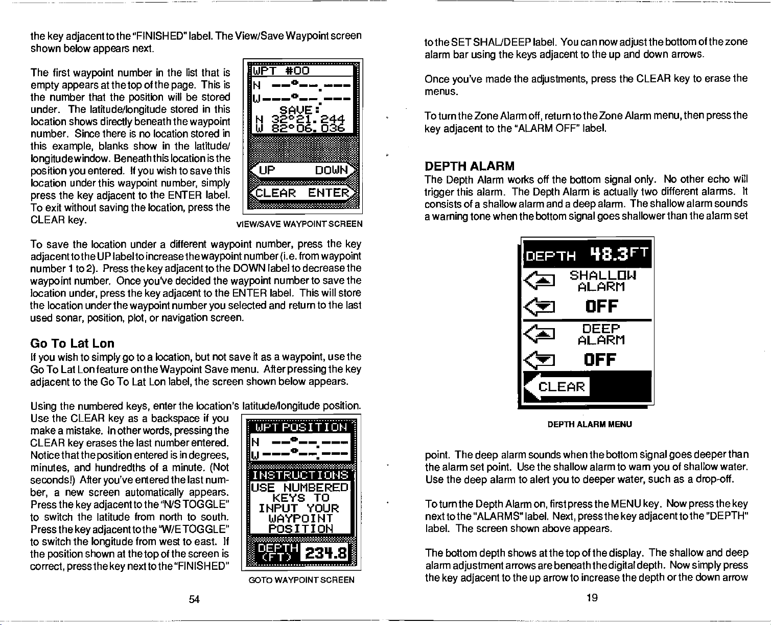
the
key adjacent
shown below
The first
empty appears
the number that the
under. The
location shows
number. Since
this
longitudewindow.
position you
location under this
press
To exit without
CLEAR
waypoint
example,
the
key.
to the 'FIN ISHED" label. The View/Save
appears
number in the list that is
at the
latitude/longitude
directly
there
blanks show
Beneath
entered. If
waypoint
key adjacent
saving
next.
of
the
top
position
beneath the
is no location stored in
the
will
in
this location is the
wish to save
you
number,
ENTER label.
to the
location, press
This is
page.
be stored
stored
in
this
waypoint
the latitude/
this
simply
the
Waypoint
screen
WPT *00
H
——°——.
u———0
SAVE
32°21. 244
N
Ui 82°06. 036
I
.
binS
VIEW/SAVE WAYPOINT SCREEN
to the SET SHAL/DEEP label. You can now
alarm bar
Once
you've
menus.
To turn the Zone Alarm
key adjacent
DEPTH ALARM
The
Depth
trigger
consists of a shallow alarm and a
a
this alarm. The
warning
the
using
made the
to the "ALARM OFF" label.
Alarm works off the bottom
tone when the bottom
keys adjacent
adjustments,
return to the Zone Alarm
off,
Depth
to the
Alarm is
deep
signal goes
up
press
signal only.
actually
alarm. The shallow alarm sounds
adjust
and down
CLEAR
the
shallowerthan
arrows.
key
then
menu,
No other echo will
two different alarms.
bottom of the zone
the
to erase the
the
press
It
the alarm set
To save the location under a different
adjacent
number ito
waypoint
location
the location under the
used
tothe UP label to increasethe
Press the
2).
number. Once
under,
sonar, position, plot,
press
key adjacent
you've
the
key adjacent
waypoint
or
navigation
waypoint
decided the
number
waypoint
to the DOWN label to decrease the
to the ENTER label. This will store
you
screen.
number,
number
waypoint
selected and return to the last
(i.e.
number to save the
press
from
the
key
waypoint
DEPTH q•3FT
SHALLOW
ALARM
OFF
DEEP
Go To Lat Lon
If
wish to
you
Go To Lat Lon feature on the
adjacent
the numbered
Using
Use the CLEAR
make a
CLEAR
Notice that the
minutes,
secondsl)
a new screen
ber,
Press the
to switch the latitude from north to south.
Press the
to switch the
the
position
correct,
simply go
to the Go To Lat Lon
mistake. In other
erases the last number
key
position
and hundredths of a
After
you've
key adjacent
key adjacent
longitude
shown at the
the
press
PDF compression, OCR, web-optimization with CVISION's PdfCompressor
to a
location,
Waypoint
label,
enter the location's
keys,
as a
key
key
backspace
words,
entered is in
entered the last num-
automatically appears.
tothe "N/S TOGGLE"
to the "W/ETOGGLE"
from west to east. If
next to the "FINISHED"
pressing
degrees,
minute.
of the screen is
top
54
but not save it as a
Save menu.
the screen shown below
latitude/longitude position.
if
you
the
entered.
(Not
waypoint,
After
pressing
twa • _-- u •
H
——°——•———
USE NUMBERED
KEYS TO
INPUT YOUR
WAYPOINT
POSITION
_______________
3010 WAYPOINT SCREEN
use the
the
appears.
key
The
point.
the alarm set
Use the
To turn the
nexttothe "ALARMS" label.
label. The
The bottom
alarm
the
deep
adjustment
key adjacent
alarm sounds when the bottom
deep
Use the shallow alarm to warn
point.
alarm to alert
Alarm
Depth
screen shown above
depth
to the
on,
shows at the
arrows are beneath the
up
arrow to increase the
ALARM
OFF
DEPTH ALARM MENU
signal goes deeper
of shallow water.
you
to
you
deeper
first
press
Next, pressthe key adjacentto
appears.
of the
top
water,
the MENU
display.
digital depth.
19
such as a
Now
key.
The shallow and
Now
or the down arrow
depth
than
drop-off.
the
press
the "DEPTH"
simply press
key
deep
Page 24

to decrease it on the desired alarm. The shallow alarm was
this
was
example,
pressed.
so the
key adjacent
to the
arrow on the Shallow Alarm
up
adjusted
in
number that
save
yourpresent position,
adjacent
appears.
already
to the
has a
position assigned
pressthe
"VIEW/SAVE LL" label. A screen similar to the one below
WAYPTSAVE
to it
using
key.
this
Now
method.)
pressthe
To
key
The
only
deeper
sound which alarm was
alarm
deep
difference is the sound the
than the alarm
adjusts
and activates
depth.
triggered.
exactly
alarm makes when the bottom
deep
This tone is different so
like the shallow alarm. The
you
can tell
goes
by
the
AUDIO ALARM ON/OFF
When
the UltraNavGPS
automatically
screen.
To turn the audio alarm on or
key adjacent
'Turn Alarm Sound Off" label to turn the audio off. To turn the audio alarm
on,
repeat
off now reads "Turn Alarm Sound On." Press the
to turn the
NOTE: The words
display
example,
enabled. This is indicated
to the "ALARMS" label. Now
the above
speaker
when the alarm is
the word "ZONE" flashes when the zone alarm is
is
first turned on,
off,
press
steps.
on.
corresponding
SPEAKER SYMBOL
The label that was used to turn the
to the alarm
triggered
by
the MENU
if
even
the audio alarm
a note
press
symbol
the
at
Next,
key.
key adjacent
key adjacent
in
will
the
speaker
use
still
is turned
(speaker)
thetop
of the
press
to the
speaker
to this label
flash on the
off. For
triggered.
the
y
AUTO 4r
333FT
ec
SELECT TYPE
OF ALARM
d
p
aaai
AUTh
—J
—I
is
The first
empty appears
waypoint
the number that
stored under. The
this location shows
number. Since there is no location
point
stored in this
latitude/longitude
tion is
your present position.
save this
ber, simply press
ENTER label. To exit without
location,
To save the location under a different
adjacenttothe
number ito
waypoint
location
the location under the
used
location under this
press
2).
number. Once
under, press
position, plot,
Enter New
To save a location otherthan
then
key,
shown below
keys,
the CLEAR
mistake. In
key
that the
utes,
onds!)
new screen
key adjacent
the latitude from north to south. Press the
adjacent
longitude
shown at
press
enterthe location
key
otherwords, pressing
erases the last number entered. Notice
position
and hundredths of a minute.
Afteryou've
automatically appears.
to the "W/E TOGGLE" to switch the
from west to east. If the
thetop
number in the list that is
at the
your present position
example,
window. Beneath this loca
the CLEAR
UP label to increase the
Press the
of the
top
latitude/longitude
directly
the
key adjacent
the
waypoint
or
navigation
page.
beneath the
blanks show
If
you
waypoint
saving
key.
key adjacent
you've
decided the
key adjacent
number
screen.
This is
will be
stored in
way-
in
wish to
num
to the
waypoint
to the DOWN label to decrease the
to the ENTER label. This will store
Waypoint
yourpresent position, presstheWAYPTSAVE
the
key adjacent
appears. Using
you
as a
backspace
entered is in
entered the last
to the "N/S TOGGLE" to switch
of the screen is
to the "INPUT LL
the numbered
wish to save. Use
if
make a
you
the CLEAR
degrees,
(Not
number,a
Press the
position
correct,
press
WPT
*00
N
SAVE:
N 32°21. 244
14 52°06. 036
the
the
waypoint
you
________________
________
___________
jJP
___________________
AR
__________________
VIEW/sAvE WAYPOINT
number,
number
waypoint
selected and return to the last
WPT"
_____________________
press
from
(i.e.
number to save the
label. The screen
i.oJ • au.ii U •
min-
sec-
key
ENTER WAYPOINT SCREEN
NUMBERED
JSE
KEYS TO
INPUT YOUR
LiJAYPOINT
POSITION
SCREEN
the
key
waypoint
20
53
PDF compression, OCR, web-optimization with CVISION's PdfCompressor
Page 25

Charts
true north.
either have to convert
The UltraNavGPS can
When it's turned on for the first time
press
label. Now
BEARING" label is on this
"SELECT
show information
above
Press the
are
usually
ltyou plot
MENU
the
TRUE BEARING" label. This will cause all
steps.
key adjacent
laid out
key,
press
in
The menu now reads "SELECT MAGNETIC BEARING".
according
acourse
then
the MENU
degrees
on a chart
magnetic readings
display navigation
the
press
key
page. Finally, press
true. To switch
this menu for
to
key adjacent
to a Mercator
usingthe Mercatorprojection, you'll
to true
information in
magnetic
two times.
magnetic
projection
or use true
is used. To switch to
to the 'CHANGE SETUP"
The "SELECT TRUE
the
key adjacent
navigation displays
back to
magnetic, repeat
data.
which uses
readings.
magnetic
or true.
to the
true,
to
the
SONAR MENU
-
PAGE
2
CHART CURSOR
The UltraNavGPS has a chart cursorthat allows
depth.
display
side shows the line's
30.2 feet.
To
adjacent
the one below
The cursor is
from left to
display
the chart
right. A depth
cursor,
to the "TURN CHART CURSOR ON" label. A screen similar to
appears.
simply
depth.
a horizontal line that extends across the
box at the end of the line on the
In the
example below,
the menu
press
keytwice.
to
you
the cursor
pinpoint
Now
press
a
target's
(line)
the
right
is at
key
WAYPOINT NAVIGATION
HOW TO SAVE A WAYPOINT
Waypoints
to.
Waypoints
other
traNavGPS's
world
100
waypoints.
latitude/longitude positions
Saving
(Quick
The UltraNavGPS lets
only
are locations
are useful for
fishing
simply by pressing
or
memory
You can store
Present Position as a
Save
Feature)
one
key press.
a wreck or other locations
To save
QUICKSAVE
assigns
indicating
your present position
key.
the first available
the location has been stored.
on
the earth's surface
marking shipwrecks,
navigational
makes it
locations.
easy
a few buttons. The UItraNavGPS can store
your present position
as
waypoints.
save
you
This "Quick Save"
The UltraNavGPS takes the
your
quickly
as
waypoint
and
that
Storing waypoint's
to return to
wish to
you
hot
fishing spots,
virtually any point
as a
waypoint
or return
go
in the UI-
or enter
Waypoint
present
feature lets
easily.
waypoint, simply press
number to it. It then sounds a
position
as a
waypoint
save the
you
present position
position
the WAYPT
and
in the
to
up
with
of
and
tone
Use the
down to the desired
To turn the chart cursor
adjacentto
returns to the sonar screen without the chart cursor.
r
keys adjacent
the 'TURN CHART CURSOR OFF" label. The UltraNavGPS
TURN CHART
to the
depth.
off,
and down arrow to move the cursor
up
press
the menu
twice.
key
AIJTO
'18.3
FASTRAK
.4
.
SONAR MENU
PAGE 2
____
MORE4
0
CHART CURSOR
Now
FT
up
the
press
key
---20
4-c
..
e
or
Saving
The "Quick Save" feature doesn't let
have to use the next available number when
and Save method lets
position
PDF compression, OCR, web-optimization with CVISION's PdfCompressor
Present Position - View and Save Method
is stored in.
you pick
(Note:
select the
you
using
the
waypoint
You can store a
52
waypoint
that method. The View
number that
position
number. You
under a
your present
waypoint
NOTE: The Chart Cursor won't work when FASTRAK is on or
Alarm or Zoom Window bars are activated.
21
if
the
Zone
Page 26

SONAR MENU
FASTRAK
This feature converts all echoes to
short horizontal lines
far
operate
you
rectly
useful for ice
fishing
moving,
out lines on a normal chart
FASTRAK converts the
vertical bar
makes a useful addition to
stationary
To turn FASTRAK
key twice,
tothe'TLJRN FASTRAKON" label. To
turn it
'TURN FASTRAK OFF' label
instead of the "TURN FASTRAK ON"
label.
side.
right
normally.
a
rapid update
under the boat. This makes it
at anchor. Since the unit is not
fish
graph
location.
then
off, repeat
-
The
graph
fishing,
signals
that,
on, press
press
the same
PAGE 2
on
the
display's
continues to
FASTRAK
of conditions di-
or when
are
with
the
key adjacent
long,
display.
graph
practice,
fishing
the menu
steps.
appears
gives
you're
drawn
to a
at a
The
Plot Radius
Use this menu to
The
UltraNavGPS is turned on for the
The available
2, 5, 10, 20,50,
"zoom in"
course or "zoom out" to
position, present position, track,
destination.
Plot
The
solid line behind
position
whenthe unit isturned on forthefirsttime.
change
whiletheunit
the
The screen shown at
available
seconds.
press
time. The UltraNavGPS
to the
radius is .05 statute miles
plot
Update
plotter
is
the
key adjacent
plot updatetimes
1, 2, 5,
the
key adjacent
plotter
change
radii are
plot
and 100 miles. This lets
see small variations in
to
shows
your present position.
updated
update rate, press
isintheplottermode. Nowpress
tothe PLOT UPDATE label.
screen
the
plotter's
.05, .10, .25,
see
track
your
once
every
the MENU
right appears.
are
2,5, 10,
and 10 minutes.
to the desired
immediately
the new time.
using
radius.
when
first time.
.50,1,
your
your starting
course,
by drawing
two seconds
and 30
Simply
update
returns
the
you
and
a
The
To
key
The
r2
±oMI
:i1
EELa10°
PLOTTER RADIUS MENU
=-
—
33
-
s-
r
103
k
EM:
OM
—
..
CLEAR
-
PLOTTER UPDATE MENU
SONAR MENU-PAGE 3
Clear Plot
SELECT DIGITAL DISPLAYS
The
UltraNavGPS
depth, speed,
and distance
ture,
portion
ST-T
It can also show
tude/longitude.
UltraNavGPS is first turned
the
on each
of the
speed/temp
is
depth
displayed.
digital display
can
display
surface
screen,
watertempera-
on the
log
if the
sensor is attached.
your position
When the
You can turn
as desired.
upper
optional
in lati-
on,
only
the
left
22
a
________
I
CLEflR NOR:
I.-
To clearor erasethe solidtrack line fromthe
selection.
pressed,
TRUE and MAGNETIC POSITION
Most
True north is the
Magnetic
miles to the south of true
The
plotter
however
people
realize there is a difference between true and
top
north is the location our
will continue to draw
your present position
of the world. It's where all lines of
compasses point.
at a location in Canada.
north,
will be centered on the screen.
51
screen,
usethe Clear Plot menu
track after this
your
magnetic
longitude converge.
lies
It
several
is
key
north.
hundred
PDF compression, OCR, web-optimization with CVISION's PdfCompressor
Page 27

The destination
screen. In this
present position
present position
from the
plotter
waypoint
example, waypoint
shows at the bottom of the screen. You can switch from
to Distance to
menu.
An arrival alarm can be set to sound a tone when
distance to the destination. See the section on alarms for more information
about the arrival alarm.
number
ga(DTG)
displays
number 10 is the destination. Your
in the lower left corner of the
and Course over
you
A
I?
ground (COG)
come within a
preset
ii — iflfl1
PLOTrER MENUS
Pressing
displays gives you
the MENU
a new set
of the items on the first menu
to the
only
Plot
This menu switches the
present position
water
shown below
for
present position. Pressing
displays
plotter.
depth.
plotter.
Display
to Distance to
depth.
Press the
appears.
Distance to
the
Press
The unit returns to the
key
while the
key
of
menus. Most
PLOTrER MENUS
display
go (DTG)
key adjacent
Now
press
go (DTG)
next to the "SHOW DEPTH" label to
plotter
plotter
page pertain
at the bottom of the
and Course
to the Plot
the
key adjacenttothe
the
key adjacent
and Course over
screen after the
Display
to
plotter
overground (COG)
label and the menu
SHOW POS label
SNOW NAV label
the
ground (COG)
key
screen from
display
is
pressed.
or
on the
water
To select the
the menu
press
the
press
DIGITAL DISPLAYS" menu at the
digital displays
three times.
key
key adjacent
to the "SELECT
menu,
top
first
Next,
of
the screen. A screen similar to the one at
right appears.
Now
sired
temperature display on, press
adjacent
Once
the
temperature
ON". You can turn each
individually.
Press the CLEAR
seconds and the menus
NOTE: The "GPS IS OFF" means the GPS
screen is off. This screen does not
SONAR MENU
the
press
display.
key adjacent
For
example,
to turn the
to the "TEMP. IS OFF" label.
you
do
the
this,
display
and read "TEMP. IS
display
to exit
key
will
automatically
-
PAGE 3
to the de-
the
key
will show
on or off
from this menu or wait
turn the GPS on or off.
SELECT DIGITAL SIZES
The
digital displays
or
three times.
SIZES" menu. The screen shown below
large.
To
change
can be shown in three different sizes
the size of the
Now
press
the
digital display,
key adjacent
DEPTH IS ON
S C' .8 FT
TEMP. 15. OFF
d
SPEED IS OFF
—fl
-'4'
CLE F: I'1'J RE
clear.
position display
first
to the "SELECT DIGITAL
appears.
_________
approximately
on the sonar
-
small, medium,
the menu
press
ten
key
A.
SELECT DIG.
SIZES
i: [u]$SVt!
: LI1J,. •jp ci
r
lii
L
E]
'41
'
b
MORE
PLOT DISPLAY MENU
PDF compression, OCR, web-optimization with CVISION's PdfCompressor
50
PLO1TER WITH DEPTH DISPLAY
23
Page 28

Now
simply press
pressthe key adjacenttothe
in small numbers.
numbers.)
The
large digital
in
large. Pressing
different from other menus. This menu lets
information,
digital displays,
restores the normal menu
the
key adjacent
The GPS
(Note:
selection erases the chart and shows the
the menu
and
the
digital display
adjust
operation.
placing
to the desired label. For
"SMALL"
the
label,thedigital displays
displays
key gives only
back in the medium
alarm.
depth
are
one menu
SELECT DIG.
SIZES
n-
s
'4
a-
example,
always
you go
Returning
shown in small
digital
if
you
are shown
displays
which is
page
back to chart
select
size,
to the chart
PLOTTER
The
plotter
If
you've
present position,
waypoint
To use the
below
The
The solid line is
traveled. The circle is a
just
marked with
The circle's radius
screen. This is the distance
the
edge
is shown at the bottom
If
your present position
of the
display,
closer to the center of the
displayed
lets
recalled a
to use the
plotter, simply press
appears. _____________________
flashing
of the circle.
circle,
then re-draws
on the
see
you
cross is
your
North, South, East,
the UItraNavGPS clears
your
waypoint,
and destination.
plotter.
your present position.
track,
displays
Your
of the screen.
starts to move outside
your present
plotter.
course and direction of travel on the screen.
the
plotter
However,
PLOT
the
or
from the centerto
screen. Your
you
path
compass
and West.
at the
top
present position
shows
you
key.
have
rose
of the
the
position
present position
starting location,
your
do not have to recall a
A screen similar to the one
1w •1
will
always
-I
E
be
To clear the
plotter
screen,
the Plotter Menus section.
see
os
SMALL DIGITAL DISPLAY
SONAR MENU - PAGE 4
SELECT UNITS OF MEASURE
The UltraNavGPS can
water
temperature
miles
menu switches all
cannot switch each
To
screen at the
to the "SELECT UNITS OF MEASURE" label. The screen at the above
right appears.
O,
equivalent. Repeat
hour or
per
change
NAUTICAL MILES" label. The unit of measure
the units of
top
Now
display
in
degrees
knots,
displays
display individually.
measure,
of the next
pressthe keyadjacenttothe
these
the water
Fahrenheit or
and distance
to their metric
first
page appears.
to switch the units of measure
steps
in feet or
depth
Celsius,
in miles or nautical miles.
(log)
equivalent
press
24
the menu
Next,
and back
key
press
"CHANGETO
change
meters,
speed
four times. The
the
surface
in
statute
This
You
again.
key adjacent
METERS,
metric
to the
again.
Plotting
the
Using
effects of wind and current on
fixed
first recall a
Waypoint
tion.)
similar to the one below
The "5" is
your position
The
and the "0" is the destination
point).
waypoint
shortest,
point
to the
plotter
point.
Then
flashing
If
you
in the route. The dotted line is the
most direct course from the
to the destination. Follow this line to
waypoint.
PDF compression, OCR, web-optimization with CVISION's PdfCompressor
a
with
To use the
waypoint
Recall section for more informa-
your starting
Waypoint
with a recalled
or start a route.
the PLOT
press
when
you
cross is
are
using
waypoint
your
in this
plotter
key.
appears.
location.
recalled the
your present position,
(recalled way-
a
route,
it's the first
or route is an
boat. It also
manner,
(Seethe
A screen
This was
waypoint.
starting
get
49
wayto
easy
simplifies navigation
see the
i'
PLOTTER SCREEN
to a
E
Page 29

the outside line and the CDI
and
is 0.1 miles. The CDI
error
the section
Using
display
NAVIGATION
The
navigating
present position,
to
ing
(XTE),
navigation
press
adjacent
screen similar to the one
on GPS alarms to
the
digital displays
top
lets
you accurately
at the
SCREEN
navigation
Waypoint (BRG),
and
the MENU
screen
to a
waypoint.
distance
waterdepth (DEPTH).
screen,
first recall
key.
to the "NAy. SCREEN
range
same as the CDI alarm
isthe
range
change
at the bottom
is used when
It shows
to
go (DTG),
Cross Track Error
a
waypoint,
Next, press
at
right appears.
the
of the screen
steer the boat to a
you're
Bear-
Tousethe
the
label. A
is 0.2
CDI
your
then
key
then
miles,
range.
along
— a.uu
31°OtB'12
IN
cross track
your
setting.
with the
waypoint.
graphical
Ji —
i s2ffO.ç3
RO.22
See
d
'
4
MORE
SONAR MENU - PAGE
4
UNITS
MEASURE
ARE IN
FEET
MILES
-A
l_:HRNI.jE
I1ETEF.:S
NALIT. F'l I
or
Tu
LEE;
NAVIGATION SCREEN
NAVIGATION SUMMARY SCREEN
Another
Navigation
This is the
Again,
To use
Now
MARY SCREEN label.
below
To Go
ing
(COG),
(ALT),
(DATE),
Please
the
position
ellipsoid
manual for more
navigation
screen,
it's used when
first
it,
the
press
appears.
(DIG),
to
Waypoint (BRG),
Speed
time of
Fix,
and water
note that altitude is also affected
ellipsoid
and
and
screen
Navigation Summary
press
key adjacent
This
Cross Track
Over Ground
day (TIME),
used
altitude. Errors in the Altitude
levels of SA. See the PCF and
high
information.
PDF compression, OCR, web-optimization with CVISION's PdfCompressor
is availablethat shows
but in smaller numbers. _______________________
screen.
navigating
the
display
Course Over Ground
depth (DEPTH).
the GPS to calculate
by
to
awaypoint.
MENU
to the
The screen shown
shows Distance
Error
(SOG),
twice.
key
NAV SUM-
Bear-
(XTE),
Altitude
today's
date
48
more information than
SUMMARY
IJTG(MI) 2.89
XTE(MI) 0.06
MAG BRIB 039°
MAO COG
SOG(MPH)
ALT (FT) 10
FIX
TIME
DATE 08/08/91
DEPTH
by
display
(FT)
__________
can be affected
Accuracy
9:49:23
sections
the
045°
18.49
9
both
by
in this
BACKLIGHTS
The UltraNavGPS
these
on,
press
the "TURN BACKLIGHT
same
steps.
has internal
the menu
PRESET
The UItraNavGPS
display
is retained even if
return the sonar
times. Now
unit will
settings.
NOTE: Preset also resets
initialized after a
contrast,
press
reset,
saves all
and more in
power
settings
the
key adjacent
to a sonar screen with all
return
preset.
lightsforthe display
four
key
ON" label. To turn the
settings
battery
is disconnected
to the
factory
all GPS
doesn't erase
It
then
times,
as
such
backed-up memory.
from the unit. If
defaults, press
to the "PRESET
settings!
25
The GPS
waypoints
and
keyboard.
the
press
backlights
sensitivity,
the MENU
UNIT" label.
of the
will have to be re-
or routes,
adjacent
key
off, repeat
chart
This
memory
you
key
original
however.
To turn
to
the
speed,
need to
four
The
factory
Page 30

SONAR MENU - PAGE 5
SPEAKER VOLUME
The
speaker
low
and
when
high
change it,
times. Now
the 'SET
label.
ume,
To switch back to the
repeat
DISPLAY
The unit's
justable
conditions. To
the
menu
menu
shown above
the
press
DISPLAY
display
the left side of
increase the
key adjacent
decrease
the down arrow.
to erase
key
approximately
automatically
MEMORY
The UltraNavGPS
display contrast,
is retained
the
memory
M EMORYSAVE
affect GPS initial
feature on
the
press
volume has two
high.
The
speaker
volume is
the unit is first turned on. To
first
press
SPEAKER VOLUME LOW"
the
press
the
above
the menu
key adjacent
steps.
CONTRAST
display
to suit
key
key
CONTRAST' label. The
contrast arrows
it, press
contrast is ad
different
adjust
it,
lighting
first
press
five times. The
appears.
next to the "ADJUST
appear
the screen. To
contrast,
to the
the
press
arrow. To
up
the
key
next to
Press the Clear
menu,
or wait
ten seconds and it
clears.
saves all
and
if
even
power
save feature
OFF" label on the fifth sonar menu
settings, waypoints,
again,
press
next to the "TURN MEMORY SAVE ON"
key
in
more
is disconnected from the
off,
the MENU
L'iJLLIF'lE
______________
-
steps
five
key
to
a
TURN
vol
high
FT
_________
1
Now
on
the
settings
battery backed-up memory.
such as
the
press
key adjacent
or routes. Toturn
until the fifth
key
sensitivity,
If
unit.
page.
the
page
SPEnKER
L 0 Li
MEMORY
___________
Fl ORE
-20
-C
chart
speed,
This
memory
wish to turn
you
to
the "TURN
This does NOT
memory
appears,
label.
save
then
degrees,
(COG).
mode the UltraNavGPS is in. Course over
is
travelling.
heading
Fix
filter in
one
is the small
the
around."
jitter;
number and HDOP
shown on the
(selective availability).
Water
50.853 minutes. Below
This is
expressed
In other
due south.
displays
beneath the SaG. Fix
the receiver is
As the fix number
(1).
position changes
boat
perfectly
Very
still,
small
it's normal and
display
shows at the bottom of the screen. This is the
depth
words,
working.
you'll
position changes
happens
numbers are
should also be
Also see
water from the face of the
the
in
present position
degrees
if the
true or
COG is 180
shows how well the
The best
decreases,
around a
see the
the
location. In other
position
will
in all electronic
then the
good,
good, excluding
the
Engineering
transducer to the bottom.
STEERING SCREEN
The
steering
This is called a
To Go
and water
Your
present position
shows the direction the boat is
if
you
then
you
line
extending
travel
circle on the center line.
depicted by
display.
two circles will move
travel
past
will move to the bottom of the
The numbers
the CDI
of how faroff course
the circle is
screen shows a
pictorial
Course Deviation Indicator or CDI. It also
(DTG), Bearing
depth (DEPTH).
to
Waypoint (BRG),
is shown
by
heading
the circle
steer the boat with the arrow
will arrive at the
from the circle is
directly
to a
anothercircle at
As
you approach
the
waypoint,
immediately
in miles. This
range
halfway
waypoint.
yourtrack.
The
to
waypoint
waypoint, try
thetopofthe
the
waypoint,
closer
together.
the
waypoint's
display.
below the CDI are
gives you
are. For
you
between the course line
example,
viewof
relative to the
always
The solid
keep
CDI
If
you
circle
an idea
is course over
magnetic, depending
ground
is the direction the boat
degrees,
fix
number is nine
position's "jitter"
displayed
constantly
navigation
occur, This is called
latitude/longitude position
then the boat is
latitude/longitude
(9),
increases. Jitter
words,
on the unit
devices.
ground
on the
the worst is
if
you
"jump
If
the fix
the effect of S/A
Screen section.
of
depth
boat and coursetravelled.
your
shows Distance
Course Over Ground
with an arrow inside. The arrow
waypoint.
pointing
To
the
is
towards the
(COG),
In
theory,
waypoint,
the
if
STEERING SCREEN
hold
26
PDF compression, OCR, web-optimization with CVISION's PdfCompressor
47
Page 31

MENUS
The UItraNavGPS uses menus to
through
Pressing
tures, allowing you
your
which are accessed
the menu
second menu
key
menus,
POSITION/NAVIGATION
The UItraNavGPS
and a
showthe most
the
the
Navigation
Summary
Menu
A detailed
the unit's functions and features.
the MENU
accesses these fea-
key
to customize the unit to
needs. There are several menu
by repeatedly pressing
For
key.
page. simply press
two times. If
simply press
steering
Plotterscreen)
key adjacent
key
indicator screen. These
important
screen
screen selection is on the second menu screen.
twice to see the second menu
description
example,
ever
you
get
the CLEAR
DISPLAYS
has a
position
available
is
data in
large digits.
first
by
to the desired screen label. The
selections are on the first menu screen. The
of each screen follows.
guide you
"pages"
to see the
MENU
the
lost in the
to exit.
key
screen,
two
displays
pressingthe
page.
g
navigation
were
Each of these screens
MENU
screens, a plotter,
carefully designed
then
key,
Position,
Simply press
pressing
Steer,
Navigation
to
(except
and
the
SONAR MENU - PAGE 6
DIGITAL SONAR
When the
the
located
This
tal sonar built
only
bottom,
the
bottom,
bottom
The
features
feature.
To turn the
key adjacent
on
again, repeat
SONAR MENU
FISH I.D. ON
UItraNavGPS is turned on for
first
time,
atthetop
display
comes from
the bottom
the last known
display.
will
it
depth again.
sonar can be turned
digital
off
also,
digital
the
digital depth display
left cornerof the screen.
a
separate digi-
into the unit. It
depth.
When the
automatically display
such as auto
sonar
to the "TURN
the same
If it loses the
depth
digital
off,
-
PAGE 7
will flash on
press
DIGITAL SONAR OFF" label. To turn
steps.
rTIJPNDIr.iITAL.
TURNING
is
displays
finds the
the
however this also turns
off,
sensitivity,
the Menu
THE DIGITAL
WILL DISABLE
ALL OF THE
AUTOMATIC
FEATURES
a
AR
____________
auto
ranging,
six times. Now
key
OFF
all automatic
the Fish l.D.
and
press
the
it back
POSITION SCREEN
The
position
ized. The
position,
over
ground (SOG),
depth (DEPTH).
of the screen shows if
top
(latitude/longitude only)
longitude plus altitude).
Your
present position displays
the screen
This is
thousandths of
page,
8.642
PDF compression, OCR, web-optimization with CVISION's PdfCompressor
screen
position display
course over
automatically appears
shows
ground (COG),
satellite
The
position display
or 3D fix
in
latitude/longitude
expressed
the
present
minutes latitude. The
in
degrees,
a minute.
position
Forexample,
yourpresent
and water
fix,
have a 2D
you
(latitude/
nearthe
coordinates.
minutes,
is 31
degrees,
longitude
46
speed
at the
top
on this
is 82
the UltraNavGPS is initial-
after
_____________________
of
and
POSITION SCREEN
The UItraNavGPS's
ture is an effective tool
noise.
undesired
trical
bilge pumps, engine
and
face of the
from the
produce
play.
The UltraNavGPS has atwo
is turned
(identified by
rejection
In sonar
signal.
and mechanical sources such as
wiring,
airbubbles
transducer,
engine.
unwanted marks on the dis-
the noise
on,
level to
noise
rejection
in
combating
terms,
It is caused
In
random lines or dots
high.
noise is
by
ignition systems
passing
allcases,
rejection
overthe
even vibration
noise can
step
is on normal.
fea-
any
elec-
noise
rejection system.
on the
display), try changing
27
NOISE REJECTION
REJECTION
a
TURN
a
CLEAR
If
have noise
you
OFF ASP
I.
MORE
When the unit
problems
the noise
Page 32

To do
adjacent
The
screen at the lower
"SET
The noise should be cleared from the
the screen. If it
engine,
servicecenter,
this,
first
press
the menu
seven times. Now
key
press
to the "SET NOISE REJECTION" label.
right appears.
HIGH' label. The screen will clear and return to the chart screen.
isn't,
you may
Now
display
have a
problem
or transducer installation. Check with
orthe
Eaglefactorycustomerservicedepartmentfor help.
SET
NOISE
REJECTION
the
press
as new echoes scroll across
key adjacentto
with electrical
local
your
dealer, Eagle
CHART NOISE
REJECTION
IS SET
NC' F: II AL
the
key
wiring,
the
Enter
The Time/Date screen needs
numbered
14:00,
example,
the entire
Time/Date
enter the
keys,
enterthe
Next,
etc.).
October
year,
'mm
4,
i.e. 1991
present
present
1991 is entered as 10:04:1991. Make certain to enter
(not 91.)
SGlIJflI ..........,
H
A
H
A
— -
—
—
•
(HH:MM)
- -
(MM :DD :VYVY)
local time and
your
time
date in the
m
present
first,
24 hour time
using
month/day/year
___________________
date. With the
SIlI]fll
14:28
(HH:MF'l)
H
V12:16:1991F
<MM LID 'r"r')
(2:00 pm
format. For
=
F
I
a
eIuJEUJSiEa
-
MUSE
SONAR MENU -PAGE 7-ASP
(Advanced
ASP is a
continually
echoes are
with a minimum of screen
it
typically
the
sensitivity.
To turn ASP
thetop
Off ASP" label. The
turn ASP on
of the next
Signal Processing)
program
monitors the
noise,
allows
off, press
again, repeat
embedded in the
signals
rejects
to
you
operate
When the UltraNavGPS is first turned
the menu
page appears.
will
unit
from the receiver. It determines which
them,
allowing target
clutter. This feature is
the boat at all
seven
key
Now
press
return to the sonar screen with ASP off. To
the above
steps.
(SET
HIGH
a
UltraNavGPS's
echoes to be
especially useful,
speeds
times. The menu shown at
the
key adjacent
computer
displayed
without
on,
adjusting
ASP is enabled.
tothe "Turn
I
that
since
24 HOUR
FORMAT
If
make a
you
number. After the last number in the
label
appears.
a correction.
and
date. Press the
correct. This
appears
The
next.
present position display
mistake, press
Press the
The screen
key
completes
the unit has not calculated
the unit is
Never
navigate
longitude!
than one method to
If
move a
you
used the UltraNavGPS
unit. If
you preset
the unit. The "Initial
returns
shouldn't need to
you
for
ready
This meansthe unit is not usablefor
to the initial
navigation.
with
this unit when the
navigate.
distance with the unit turned off from the last time
long
(100
the
UltraNavGPS,
Setup"
repeat
the CLEAR
next to the EXIT label if
key
will
clear and
next to the
the initialization
at the
top
your latitude/longitude.
WARNING!
miles or
menu selection on the GPS' second menu
setup
these
more), you may
menu,
steps.
ENTER EXIT
key.
is
year
ENTER
entered,
will
you
label
procedure.
of the screen
position
you
screen flashes the latitude/
navigation. Always
will
definitely
when needed.
This will erase the last
the "ENTER EXIT"
need to make
you
need to re-enter both time
if
the time and date are
The
position
flashes,
Whenthe
need to re-initializethe
flashing stops,
need to re-initialize
Otherwise,
screen
indicating
use more
that
you
page
you
28
45
PDF compression, OCR, web-optimization with CVISION's PdfCompressor
Page 33

Press the
to switch the latitude from north to south.
the
Press
to switch the
the
position
correct,
ISHED" label. The Altitude screen
next.
adjacent
key
key adjacentto
longitude
shown at the
the
press
to the "N/S
the "W/E TOGGLE"
from west to east. If
top
key adjacent
TOGGLE'
of the screen is
"FIN-
to the
appears
ni
w 36°08,.6'}2
LI 95°50.853
E
7TOGGLE
SONAR MENU- PAGE 7-
FISH l.D. OFF
SURFACE
CONTROL-SCC
The
markings extending
the zero line can extend
the surface. These
surface clutter and are caused
action,
and more.
sion,
CLARITY
markings
boat
wakes, temperature
downwards from
manyfeet
are called
by
below
wave
inver-
-J
SEJ
F.: E .J E C TI OH
MuSE
Enter Altitude Screen
The screen shown below is the Altitude
needs to
ground.) Again,
keys
label when
adjacent
negative.
standing
"35",
this
screen. This is the last initialization screen.
know
to enter
then
step
your
you're
to this label to switch the altitude
For
in is 35 feet below sea level. You would need to enterthe
press
is
completed,
+
elevation above sea level.
your
an
approximation
altitude data. Press the
done. A new label
example, suppose you're
the
key adjacentto
the UItraNavGPS switches to the
— uu•ai ia
FT
entry
is
usually
key adjacent
appears: (+1- TOGGLE).
in Death
the +1- label to
-
lu1*. nJ
USE NUMBERED
KEYS TO
INPUT APPROX
ALT I TUDES
PUSH CLEAR
UNKNOWN.
IF
screen. The UltraNavGPS
(Not your height
sufficient. Use the numbered
to the
entered
you
and the
Valley
change
itto -35 feet. After
above the
"FIN ISH ED"
Press the
from
positive
spot you're
numbers
Time/Date
key
to
entry
Surface
from the
near the surface
Typically,
example,
be reduced to
There are three levels of SOC available when the
low,
adjustable
Clarity Control,
display.
maximum
the
on a 0-60 foot
approximately
medium,
and
and this menu doesn't shown on the
or SOC reduces or eliminates undesired
SOC varies
and
high.
the
gradually increasing
that SOC affects is 75% of the
depth
with maximum
range
45 feet.
When the Fish ID. feature is
sensitivity
of the
it as the
SCO,
display.
SCC IS
To
Fish l.D. feature is
MENU
key adjacent
FACE CLARITY" label.
the
level. The unit will return to the
using
the
adjust
seven
key
to the
key adiacent
level of SOC
the
5CC,
off,
times. Now
"SET CHART SU R
to the desired SOC
certain the
make
then
press
Finally, press
chose.
you
the ____________________
the
press
____________________
chart,
signals
receiver, decreasing
increases.
range
range.
surface
Fish 1.0. feature is off:
clutter would
the SOC is not
on,
For
Efl
SELECT
it
rtHED4
PDF compression, OCR, web-optimization with CVISION's PdfCompressor
44
29
Page 34

MENU-PAGE8
DISPLAY ZONE BAR
bar
The
mally disappears
It can be turned on
desired. To turn the zone alarm bar
on,
press
Now
press
"DISPLAY ZONE BAR" label. The
menu screen
alarm bar
the screen. This
alarm on it it wasn't
these
peat
off.
bar
zone alarm off.
in
used
the menu
the
disappears
displays
steps
Turning
the zone alarm nor-
afterthe alarm is set.
continuously,
key eight
key adjacent
on the
will
alsoturn the zone
already
toturn the zone alarm
it off
also turns the
times.
to the
and the zone
side of
right
on. Re-
if
_______________
-—
I.
FICIRE
GETTING STARTED
Initialization - Power On
The UltraNavGP5 must be initialized
turned on. This initialization
the
following
1. Present
2.
Elevation above sea level
3.
Today's
NOTICE! DON'T INITIALIZE THE UNIT WHILE THE uLTRANAvOPS's GPS
After the
ule are
shown at
the metric mode
distance
the
press
To
adjust
adjacent
menu
left side of the screen
the
keep
the
key adjacent
remove this
Now
key.
shown below
data:
position
date and time
power
installed,
right appears.
in
nautical
key adjacent
the
to the
appears, letting you
display
in
cable and GPS antenna mod-
pressthe
(Altitude
display contrast, press
"Ad]
and
keyboard lights on, press
to the
menu, simply press
the GPS
press
appears
process
latitude/longitude
(altitude)
SIMULATOR IS ON!
ON
key.
To switch the unit into
and
depth
miles, speed
to the "Metric On" label.
Display"
use the
to
next.
the contrast. To
adjust
"Lamp
key.
or "told where it is" the first time it's
is
usually
The screen
in
meters,
in
knots),
done
flUTIJ jr
LISS
once and
only
FT
I METRICI
(OHEJI
the
key
label. A new
on the
keys
On" label. To
the "CLEAR"
The screen
CA0Ji
<ONI
LIGHT
j
I
requires
0
ec
DISPLAY
Le
I
)
Initial Position Screen
MENU
-
PAGE 8
DISPLAY ZOOM BAR
When the UltraNavGPS is in the
manual
turned on
make
mode,
certain
the manual
MENU
key adjacent
Bar" label. Note: The zoom bar
shows
key eighttimes.
in
the Zoom Bar can be
continuously.
the
mode,
to the
the
Split
To do
UltraNavGPS
then
Now
"Display
Zoom mode.
so,
press
press
Zoom
first
is in
the
the
only
30
.4
Sb
F1ORE
This is the Initial Position Screen.
present position
chart to determine
know it. This doesn't have to be
accurate.
within one
the UltraNavGPS should be able to
find
CLEAR
mistake. In
key
that the
utes,
onds!)
the screen shown at the
automatically appears.
actual
your
key
erases the last number entered. Notice
position
and hundredths of a minute.
After
in
latitude/longitude.
your position
Typically,
degree
as a
otherwords,
you've
if
of
your present position,
latitude/longitude.
backspace
entered is in
entered the last
enter a
you
pressing
of the next
top
Use the numbered
Use a
if
don't
you
extremely
position
quickly
Use the
if
make a
you
the CLEAR
degrees,
min-
sec-
(Not
number,
page
43
to enter
keys
your
ii p ssni
N 36°O8.6'}2
w 95°50.853
USE NUMBERED
KEYS TO
INPUT YOUR
INITIAL
POSITION
PDF compression, OCR, web-optimization with CVISION's PdfCompressor
Page 35

ACCURACY
You
The DOD
However,
us and other unauthorized
coding.
Civilian GPS receivers use what's known as "C/A Code." It's
intentionally
worldwide can benefit from excellent
keeps
cally,
than
However
accuracy
called "Selective
ally
Of
horizon, signal-to-noise ratio,
(the
may
screen even
have heard tales of
may
requires accuracy
the
only
In other
military gets
words,
worsethan the
the most accurate
C/Acodecan
adequate
(as
give
for most
of this
writing),
in the hands of the world.
Availability"
added tothe
course, accuracy
more the
not be usable if the SA
system
belier),
while
also
and other factors. The smallest
you're sifting
extraordinary accuracy
of 10 to 15 meters from the satellite
this
precision.
people
the data
military's
system away
accurate
people.
so
your accuracy
depends
from
using
coming
from the satellites is
'P Code." Inthis
position
position
the
military
So,
or SA. This is
on the
the number of satellites tracked
is
because the
high,
still.
fixes.
from
potential
fixes
upto
isn't satisfied with C/A's
it's
degrading
small,
will
typically
angle
from GPS receivers.
The
the more
the
way
military keeps
precise system
manner,
Meanwhile,
enemies. Theoreti-
15 meters. This is more
it further with what's
random errors intention-
be within 100 meters.
of the satellite above the
ranges
position
will move off the
system.
encrypted.
accuracy
civilian users
the
military
potential
at one time
on the
plotter
is
is
TRANSDUCER CONE ANGLES
The sound waves from the transducer
cone
shaped
The
angle
offers
Eagle
angle.
cone
angle. Typically,
ideal for
cone
angle
of water the 20
8
degree
The 20
water,
the 8
feet
(300
more desirable. Since the sound
it can
area,
beam. This looks much like the beam from a
between the outside
edges
a choice of transducers with either an 8 or 20
The transducer
operating
allows
in shallow to medium water
to see more
you
degree
transducer covers
degree
transducer is almost
degree mostly
-
fresh
water,
penetrate
to much
supplied
wide cone
cone
100 feet
with the UltraNavGPS has a 20
angle
of the underwater world. In 15 feet
covers an area about six feet across. The
about a two foot circle.
only
in salt water. In a
-
salt
energy
deeper depths.
spread
out into the water in a
flashlight.
of the cone is the cone
degree
transducers
always
deep
water)
the narrow cone
the best to use in fresh
depths.
water
(20 degrees)
The 20
environment,
is concentrated in a smaller
angle.
cone
degree
degree
angle
are
is
Don't let this
updates
use.
Accuracy,
systems.
market
discourage you,
than other
even with SA on is still belier than most other
You've
today.
We
systems (such
purchased
hope you'll enjoy
The EAGLE GPS Module
This GPS receiver
GPS receivers. It's
acquire
information to the UltraNavGPS once
Rockwell's GPS receiver
and
advanced line of OPS marine
and track
manufacturing capabilities, Eagle brings
(manufactured by Rockwell) currently
small,
to five satellites at one time. It transmits
up
however. GPS
as
Loran),
one of the finest
it for
rugged,
technology
and fast. The five
with
navigation systems
nature has much faster
by
and
typically
navigation
many years
is much easier to
instruments on the
to come.
is used
channel
second.
every
Eagle's
By
state-of-the-art
to the consumer the most
available in the world.
navigation
in
all
Eagle
design
incorporating
lets it
position
design
50'
100'
150'
200'
I
PDF compression, OCR, web-optimization with CVISION's PdfCompressor
42
20° at 3 db
31
8° at 3 db
Page 36

Both 8
ings,
model. This
ber,
of the
even
the
signal
degree
shallow
and 20
though
the bottom
is because
edge
tells
you
degree
are
you
of the
signal
whether
transducers
signal
you
is much wider on the 20
seeing
more of the bottom. Remem-
shows
are over
accurate
give
the true
you
rocks, mud,
SIGNAL INTERPRETATION
Your UtraNavGPS
boat is
returns a
narrows
Mud absorbs the sound wave and returns a weak
sensitivity
passing.
fairly
down,
to see a better bottom
A bottom of firm
wide
then it means that
gives
signal.
an accurate
If the automatic mode is off and the
picture
sand,
have moved over a mud bottom.
you
signal.
of the bottom that
gravel,
depth.
shell,
signal.
bottom read-
degree
The rest
etc.
your
or hard
Turn
clay
signal
up
the
-
GPS
The Global
approach
Defense
HOW
to their needs of 24 hour
Basically,
Earth
11,000
system
is
IT
WORKS
Positioning System (GPS)
to
navigation yet
andthe United States
(DOD)
the
system
miles in
fullyoperational.
devised. Conceived
global positioning,
works
by using
space.
Three more satelliteswill act as
of 24. When all satellites are in
nearly anywhere
requires
in
at least three satellites to
latitude/longitude.
it locks on to at least
on Earth
A 3D
four
twenty
fix
is
satellites,
is the
newest,
by
365
GPS
days
military,the
a constellation of
will
There
place,
four hours a
give
your latitude/longitude plus altitude.)
it
21 satellites in orbit when the
be
at least four of them
day.
a "2D" fix.
displays
(A
a 3D fix.
most
high-tech
the
Department
system
a
2D fix is
is an answer
year.
satellites
spares,
will be in view
The GPS receiver
your position
of
orbiting
foratotal
When
rocks or
Big
bottom level
height.
line
extending
A
steep slope
returned from a
stumps
signal.
As
you pass
above the bottom
DIGITAL
BOTFOM
DEPTH\\
on a smooth bottom send back
The
over a
returns a wide
underwater cliff are
high
mi-ITO
38.3
height
post,
signal,
of the
signal depends
it should be
signal.
the
r
----10
FT
-C
-C
-C-c
clearly
steeper
usually
-C
signals
visible as a short
the wider.
above the
on the
target's
Signals
the widest of all.
It ta}cos three satellites to determine
As the receiver locks on to each
satellite
Each satellite has an
by measuring
the
length
extremely
satellite,
of time it takes the radio
accurate clock which tells the receiverwhen
it calculates the distance from the
the radio transmission started. The receiver
own
speed
calculate distance. Once
receiver can determine
thus it knows how
clock,
of
light!)
long
to reach it. If
you
position.
it took the radio
know time and
you
have this from three
position.
compares
signal (travelling
speed,
signal
that time
then
satellites,
to reach it.
against
its
at the
can
you
then the
32
41
PDF compression, OCR, web-optimization with CVISION's PdfCompressor
Page 37

GPS TABLE OF CONTENTS
ARCHES
GPS -HOW
ACCURACY
THE EAGLE GPS MODULE
GETTING STARTED
INITIALIZATION
MENUS
POSITION/NAVIGATION DISPLAYS 46
POSITION DISPLAY
STEERING SCREEN
NAVIGATION
PLOTTER 49
TRUE AND MAGNETIC POSITION
HOW TO
SAVING
ENTER NEW WAYPOINT
GO TO LAT/LON 54
ERASE A WAYPOINT
WAYPOINT RECALL
ROUTES
CREATING A ROUTE 56
FOLLOWING A ROUTE 58
CANCELLING A ROUTE
ERASING A ROUTE
GPSALARMS
ARRIVAL ALARM
CDI ALARM AND
SATELLITE INFORMATION SCREEN 60
ENGINEERING SCREEN
TURN NAVIGATION OFF
CHANGING STARTUP SETTINGS
PCF
NMEA COMMUNICATION
PRESET 64
MAN OVERBOARD
GPS MODULE SELF TEST
GPS SIMULATOR
SPECIFICATIONS
PDF compression, OCR, web-optimization with CVISION's PdfCompressor
IT WORKS 41
42
42
43
43
INITIAL POSITION
ALTITUDE
TIME/DATE
SCREEN 48
NAVIGATION
USING THE PLOTTER WITH A WAYPOINT
PLOTTERMENUS
PLOT DISPLAY
PLOTtER RADIUS
UPDATE INTERVAL
CLEAR PLOT
SAVE A WAYPOINT 52
CURRENT POSITION
WAYPOINT QUICKSAVE
VIEW AND SAVE WAYPOINT
OFFSET 62
SUMMARY SCREEN 48
RANGE
(CANCEL NAV)
40
43
44
44
46
46
47
49
50
50
51
51
51
51
52
52
52
53
55
55
56
59
59
59
59
60
61
62
62
64
65
66
66
67
FISH
Fish arches are created when the cone of sound
The distance to a fish when the cone first strikes
below. When the center of the
shorter as shown "B". As the
increases
again
shown in "C".
as
BOAT'S
cone strikes the
cone leaves the
DIRECTION OF TRAVEL
passes
it is shown as
the distance is
fish,
fish,
I
A B
When the
size and
example,
displayed
Fish I.D. mode is
shape
of the fish arch due to the cone
if the cone
on the
passes
UltraNavGPS
off,
the
depth
of the
over a fish in shallow
not arch at all. This
may
narrow cone diameter and the resolution limitations of the
33
water will affect the
diameter.
angle
water,
over a fish.
"A"
the distance
C
For
the
signal
is due to the
display.
Page 38

small fish
Very
a
partial arch,
fish will
Large
the arch.
probably
or a
arch,
Because
thermoclines, etc.,
to
enough
fish arches.
get
will
shape
but turn
of
water
the
sensitivity
not arch at all. Medium sized fish
similar to an arch if
the
sensitivity up
conditions,
such as
sometimes cannot be increased
they're
in
heavy
in
deeper
surface
deep
water to see
will
water.
clutter,
show
One of the best
segment
the
of the water. For
segment,
the better the screen resolution will be. The easiest
ways
to
get
example,
fish arches is to
to do this on the UltraNavGPS is
the 2x or 4x Bottom Track mode
to see detail. For the best
possible
without
deep water,
If
see fish
you
fish
get
sensitivity.
symbols
getting
this method should work to
signals
too much noise on the screen. In medium to
when the
when the Fish l.D. feature is
to
results,
expand
or "zoom" a
from 45 to 60 feet. The smaller
the Bottom Track feature. Use
with
expand
unit
the
echoes, making
turn the
sensitivity up
display
fish arches.
is in the manual
as
mode,
on, try increasing
way
it easier
as
high
but don't
the
0 PS
WARNING!
USE THIS GPS RECEIVER ONLY AS AN AID TO NAVIGATION. A
CAREFUL NAVIGATOR NEVER RELIES ON ONLY ONE METHOD TO
OBTAIN POSITION INFORMATION.
CAUTION
This GPS
shortest,
waypoint regardless
not
only
a
waypoint,
the
waypoint
receiver,
most direct
take
advantage
but will also
is
always
all GPS
(like
to a
path
waypoint.
of obstructions.
of all available
visually
available.
check to make certain a
navigation equipment)
It
provides navigation
Therefore,
navigation
the
prudent navigator
tools when
clear,
will show the
data to the
will
path
to
to
travelling
safe
NOTICE!
34
As of this
GPS
Satellites can beturned off
writing,
navigation system
operators.
as accurate as the
the
Department
as
operational.
oraccuracycan bedegraded
Remember that the
system
it's
of Defense
The
system
UItraNavGPS,
using.
39
(DOD)
is still in
or
any
has not declared the
atesting phase.
atwill
bythe system
GPS receiver is
only
PDF compression, OCR, web-optimization with CVISION's PdfCompressor
Page 39

IMPORTANT
SERVICE INFORMATION!
If
unit is not
your
troubleshooting
tomer service
working,
section before
department.
SONAR TROUBLESHOOTING
Unit won't turn on:
or
if
It
need technical
you
contacting
save
may
help, please
a service center or the
the trouble of
you
returning your
usethe
factory
following
cus-
unit.
1. Check the
2. Make certain the
to the
positive
cable's connection at the unit. Also check the
power
cable is wired
power
battery terminal,
black to
3. Check the fuse.
4. Measurethe
11 volts. If it
on the terminals are
Unit
freezes,
1. Electrical noise from
interfering
from other electrical
cable
directly
2.
Inspect
3. Check both the transducer and
securely
Weak bottom
batteryvoltageatthe
the
isn't,
locks
with the sonar unit.
to the
the transducer cable for
plugged
in to the unit.
echo,
tothe unit is
wiring
corroded,
or
up,
operates erratically:
boat's
the
Re-routing
on the boat
wiring
instead of
battery
digital readings
or the
motor,
properly.
negative
unit's
powerconnector.
defective,
battery
trolling
the
power
may help.
through
breaks, cuts,
connectors. Make certain both are
power
erratic,
The red wire connects
or
ground.
ltshould be at least
the
needs
charging.
motor,
and transducercables
Route the sonar unit's
battery
or an
terminals
accessory
a fuse block or
or
pinched
or no
fish
wires.
signals:
ignition
wiring.
orwiring
may
power
switch
be
away
1. Make certain transducer is
transducer.
itseffectiveness. Ifthetransduceris mounted insidethe
through only
NOT use RTV silicone rubber adhesive or Marinetexm.
PDF compression, OCR, web-optimization with CVISION's PdfCompressor
38 35
Oil, dirt,
andfuelcan cause afilmtoform on
one
layeroffiberglass
pointing
straight
and that it is
down. Clean the face of the
thetransducer,
hull,
securely
besure it
bonded to the hull. Do
reducing
isshooting
Page 40

Weak bottom
2. Electrical noisefromthe
the sonar to
This can cause the unit to eliminate
from the
3.
Thewatermay bedeeperthanthe
can't find the bottom
continuously.
in. If this
a
realisticone,
into shallower
4. Check the
also
drops, reducing
Bottom echo
bottom echo while boat Is
1. The transducer
flow of water
echo,
digital readings
boat's motorcan interfere with the sonar. This causes
automatically
increase its Discrimination or noise
weakersignals
display.
sonar's
while ft's in the automatic
signal
It
may change
happens, place
(forexample,
water,
battery voltage.
disappears
the
range
to
the unit in the manual
0-1
a bottom
its
OOfeet)
signal
if the
voltage drops,
to find the bottom or
ability
at
high speeds
should
and increasethe
moving
be in turbulent water. It must be mounted
may
in order for the sonar to work at all boat
waterdisruptthe sonarsignals, interfering
targets.
The technical term for this Is 'Cavitation'.
erratic,
or no fish
abilitytofind
limits
fargreaterthan
mode,
appear.
or erratic
with its
abilityto
signals (cont.):
such as fish oreven structure
rejection
the bottom. If the sonar
the
mode,
the
then
change
sensitivity.
the unit's transmitter
targets.
digital reading
speeds.
Air bubbles in the
findthe
feature.
will flash
digital
wateryou
the
As
range
you
are
to
move
power
or weak
in a smooth
bottom orother
2. Electrical noise fromthe boat's motorcan interfere with the sonar. This causes
the sonarto
automatically
This can cause the unit to eliminate
the
from
and
No fish arches when the Fish ID feature is
1. Make
problem
manual for more information.
2. The
arch,
until it leaves. If the
when it is in the center of the cone.
3.
display.
transducer cables
certain transducer is
if a
sensitivity may
it has to
Use the Zoom feature. It is much easierto
in on a small
better luck
This
enlarges
Try using
partial
be able to receive the fish's echo from the time it enters the cone
range
fish arches with a 30 to 60 foot
seeing
the
targets, allowing
increase its Discrimination or noise
weakersignals
resistorspark plugs
from other electrical
away
arch is
sensitivity
pointing straight
displayed.
not be
high
is not
See the Fish Arch section in
enough.
in orderforthe unit to
high enough,
display
of waterthan a
large
the
display
one. For
rejection
feature.
such as fish oreven structure
or
routing
wiring
the sonar unit's
on the boat.
power
off:
down. This is the most common
owners
your
a fish
display
the unit
displays
the fish
only
fish arches when zoomed
have much
example, you
than a 0 toGa
range
will
foot
range.
to show much more detail.
4. The boat must be
is
motionless,
lines.
fish
stay
moving
the
In
at a
siowtroUing
cone,
showing
to see fish arches. If the boat
speed
on the
display
as
straight
ELECTRICAL NOISE
A
majorcause
sonar's
completely
display
cover the
of sonar
problems
as random
screen with black
is electrical noise. This
patterns
of dots
dots,
or cause the unit
or lines. in severe
usually appears
operate
cases,
or not at all.
first
To eliminate or minimize the effects of electrical
cause. With the boat at rest in
electrical
equipment
on the boat off. Make certain the
the
water,
the first
noise,
thing you
engine
onyoursonarunit,thentumASP(AdvancedSignaiProcessing)off.
be a
equipment
turn on the
turn the
all electrical
noted,
if
you
or
radio, tryto
cable
steady
bottom
signal
on the
display.
on the boat and view the effect on the sonar's
bilge pump
off,
pump
equipment
then turned
find noise interference from
isolatethe
and transducercabie
and viewthe
then turn on the
has been turned
off.
problem.
away
sonardisplayfor
VHF
radio
an electrical
You can
from the
VHF radio antenna cables radiate noise when
the sonar's wires
directly
to the
If no noise
everything except
RPM with the
awayfrom
battery
displays
gearshift
on the sonar
the sonar unit is
could be one of three
using resistorspark plugs,
from
away
helps
the unit
When no noise
source is
make
engine wiring. Again,
eliminate noise
when
wiring
appears
probably
hasty
cavitation.
sonar installations which function
the boat is at rest. In
location and/or
in a location that has a smooth flow of water at all boat
placed
angle
it. You
mayneedto
to isolate
it from other
unitfromelectricalequipment,
turned
in neutral. If noise
things; spark plugs,
aiternatorfiiters,
routing
problems.
the
on thesonarunit afterail of the abovetests,
nearly
of the
Make certain to usethe in-line fuse
cable to the
power
novices or
Many
all
transducer. The face of the transducer
the cause of the malfunction will be the
cases,
transducer owners manual for the best
turn on each
Now
noise. If no noise is
and transmit.
their effect on the sonar
on,
instrument,
usuallyre-routethe
that Is
wiring
transmitting,
route the
wiring
then start the
off,
appears
alternator,
orrouting
the
power
battery.
perfectly
mounting position.
causing
on the boat.
on the
or tachometer
the sonarunit's
cable
persons
in shallow
to determine the
try
should do is turn all
is
off,
Thereshould
piece
display.
For
Keep doing
motor,
trolling
sonarunit's
the interference.
so be certain to
sonarunit's
then rnakecertain
engine.
display,
directly
to the
suphed
thenthe noise
with limited
water,
speeds.
horizontal
on the
it can
erraticly.
also. Turn
of electrical
example,
present,
this until
display
pump,
power
keep
powercabie
Increase the
the
problem
wiring. Try
powercable
battery
with
experience
orwhen
must be
Read
your
36 37
PDF compression, OCR, web-optimization with CVISION's PdfCompressor
 Loading...