

Page 1

TM
AccuMap
and
TM
UltraMap
INSTALLATION AND
OPERATION INSTRUCTIONS
Page 2

Copyright © 1998 Eagle Electronics. All rights reserved.
UltraMap™ and AccuMap™ are trademarks of Eagle Electronics.
.
WARNING!
USE THIS UNIT ONLY AS AN AID T O NA VIGA TION. A CAREFUL NA VIGATOR NEVER RELIES ON ONLY ONE METHOD TO OBTAIN POSITION INFORMA TION.
Never use this product while operating a vehicle.
CAUTION
When showing navigation data to a position (wa ypoint), this unit will show
the shortest, most direct path to the waypoint. It pro vides navigation data
to the waypoint regardless of obstructions. Therefore , the prudent navigator will not only take advantage of all a vailable na vigation tools when travelling to a waypoint, but will also visually check to make certain a clear,
safe path to the wa ypoint is alw ays available.
The operating and storage temperature for y our unit is from -4 degrees to
+167 degrees Fahrenheit (-20 to +75 deg rees Celsius). Extended storage
temperatures higher or lower than specified will cause the liquid crystal
display to fail. Neither this type of failure nor its consequences are covered by the warranty. F or more inf ormation, consult the factory customer
service department.
All features and specifications subject to change without notice.
Eagle Electronics may find it necessary to change or end our policies,
regulations, and special offers at any time . We reserve the right to do so
without notice.
All screens in this manual are simulated.
Page 3

This device complies with P art 15 of the FCC Rules. Oper ation is subject
to the following two conditions: (1) this device may not cause harmful
interference, and (2) this device must accept any interference received,
including interference that may cause undesired oper ation.
Note:
This equipment has been tested and found to comply with the limits for a
Class B digital device, pursuant to P art 15 of the FCC Rules. These limits
are designed to provide reasonable protection against harmful interference in a residential installation. This equipment generates, uses and can
radiate radio frequency energy and, if not installed and used in accordance with the instructions, may cause harmful interference to radio communications. How ever , there is no guarantee that interf erence will not occur in a particular installation. If this equipment does cause harmful interference to radio or television reception, which can be determined by turning the equipment off and on, the user is encouraged to try to correct the
interference by one or more of the f ollo wing measures:
• Reorient or relocate the receiving antenna.
• Increase the separation between the equipment and receiver.
• Connect the equipment into an outlet on a circuit different from that to
which the receiver is connected.
• Consult the factory customer service department for help.
Page 4

T ab le of Contents
INST ALLATION .................................................1
Mounting........................................................ 1
Power Connections........................................ 2
Cable Connections ........................................ 3
AccuMap .................................................. 3
UltraMap .................................................. 4
Antenna ........................................................5
T ransducer..................................................... 6
INTRODUCTION TO GPS............................... 10
OPERA TION ................................................... 12
Satellite Status Screen ................................ 13
Finding Y our Position ................................... 14
Auto Search ...........................................14
Manual Initialization................................ 14
Position Acquisition ................................ 15
Modes ...................................................... 15
Navigation Screens ................................ 15
Course Deviation Indicator (CDI) ...... 18
Map ...................................................... 18
Cursor............................................... 19
Map Setup ........................................ 20
Change Maps ................................... 20
Map Options........................................... 21
Map Orientation ................................ 21
Range Rings/Grid Lines ................... 22
Autozoom .........................................22
Map Details ............................................ 23
Earth Map On/Off ............................. 23
T ext Labels ....................................... 23
Map Detail ........................................ 23
Gray Fill ............................................ 24
Map Boundaries ............................... 24
Map Symbols.................................... 24
Locations .......................................... 25
Contour Lines ................................... 25
Plot T rail Options .................................... 25
Clear T rail .........................................25
Flash T rail ......................................... 25
Show T rail ......................................... 25
Save Trail .......................................... 25
Update T rail....................................... 26
ICONS ................................................... 26
MAP DOWNLOADING........................... 28
WINDOWS............................................. 29
Reprogram Box es.............................34
RESET GROUPS .................................. 35
WAYPOINTS .......................................... 35
Waypoint Menu................................. 35
Saving Your Present P osition as a
Waypoint (Quic k Sav e Method) ........ 35
Saving The Cursor Position as a
Waypoint........................................... 36
Saving Your Present P osition as a
Waypoint (Select Number Method)... 36
Saving a New P osition...................... 37
Waypoint A veraging.......................... 37
Project a Wa ypoint............................ 38
Selecting a Wa ypoint ........................ 39
From List.......................................39
By Name ....................................... 39
Editing a W aypoint............................ 40
Edit Position..................................40
Edit Name ..................................... 40
Edit Icon........................................ 40
Delete a Wa ypoint............................. 40
Delete All Wa ypoints......................... 41
Move a W aypoint .............................. 41
Waypoint Options .............................41
WAYPOINT NAVIGA TION ........................... 42
Navigate to a cursor location..................42
Navigate to a W a ypoint using the Map ... 43
CANCEL NAVIGATION ............................... 43
ROUTES ..................................................... 43
Create a Route....................................... 43
Add From W a ypoint List.................... 44
Add From Map .................................. 44
Delete a Wa ypoint .................................. 45
Waypoint Statistics................................. 45
Following a Route .................................. 45
Waypoint Inf ormation ........................ 47
Delete a Route ....................................... 47
SYSTEM SETUP......................................... 48
Sound .................................................... 48
Contrast ................................................. 48
Backlight ................................................ 48
Set Local Time ....................................... 48
Units of Measure .................................... 49
NMEA / DGPS ....................................... 49
Configure NMEA Output ........................ 50
DGPS..................................................... 50
Serial Communication Setup.................. 51
Reset Groups ......................................... 51
Reset Options ........................................ 51
System Info ............................................ 52
GPS SETUP................................................52
Position Format ...................................... 52
DATUM ................................................... 53
PCF (Position Correction Factor)............ 54
POSITION PINNING .............................. 55
GPS ALARMS ............................................. 56
DGPS MESSAGES ..................................... 57
SUN/MOON CALCULA TO R ........................57
SIMULA T OR ................................................ 58
Page 5

T ab le of Contents
SONAR OPERATION...................................... 59
Sonar Modes ...............................................59
Full Chart ............................................... 59
Split Chart .............................................. 59
Digital/Chart ........................................... 59
Automatic..................................................... 60
Sonar Options.............................................. 60
Sensitivity............................................... 60
Grayline.................................................. 61
Adjust Surface Clarity (SCC).................. 61
ASP (Advanced Signal Processing).......62
Range - Automatic ................................. 62
Manual.............................................. 63
Chart Options ......................................... 63
Chart Speed ..................................... 63
Chart Stop ........................................ 63
Zoom...................................................... 64
Fish ID ................................................... 65
FISHTRACK™ ....................................... 65
Chart Display ......................................... 66
Zoom Bar.......................................... 66
Zone Bar........................................... 67
Chart Cursor .......................................... 67
Digital Sonar .......................................... 67
Alarms.................................................... 68
Depth Alarms.................................... 68
Zone Alarm ....................................... 69
Fish Alarm ........................................ 69
Keel Offset ............................................. 69
Calibrate Speed ..................................... 70
SONAR TROUBLESHOOTING....................... 71
UPS Return Service ........................................ 74
Warranty ......................................................76
Datum List ......................................................77
Page 6

Notes:
Page 7

Thank you for purchasing an Eagle product! You won't find another combination GPS and sonar unit with these features and pow er for the money!
Each of our products is designed and manufactured to precision tolerances for long life under e xtreme conditions. W e hope that you'll enjoy this
product for years.
This manual covers both the Eagle UltraMap™ and AccuMap™. Both
are 12-channel GPS receivers, how ever the Ultr aMap™ also has a sonar
built into the unit. The installation of these two products vary, otherwise
the GPS operation of the two units is nearly identical.
No matter which unit you own, please read the installation section carefully, especially the transducer section. Many times future trouble can be
avoided b y carefully locating and wiring the equipment.
If you do have problems, please read the troubleshooting section in the
back of this manual. You may find the solution to your problem there. The
Eagle customer service department also has representatives av ailable to
answer your questions on our toll-free telephone lines . See the bac k page
of this manual for more inf ormation.
We want your experience with our equipment to be a happy one. Good
luck, and good fishing.
INSTALLA TION
Mounting - All Units
Install the unit in any convenient location, provided there is clearance
behind it when it is tilted for the best viewing angle. Holes in the bracket
base allow wood screw or through-bolt mounting. You may need to place
a piece of plywood on the back of thin fiberglass panels to secure the
mounting hardware. Make certain there is enough room behind the unit to
attach the power and transducer cab les.
The gimbal bracket will also accept the GBSA-1 swivel bracket adapter
that lets you rotate the unit a full 360°.
The smallest hole that allows one power or transducer connector to pass
through is 3/4".
1
Page 8
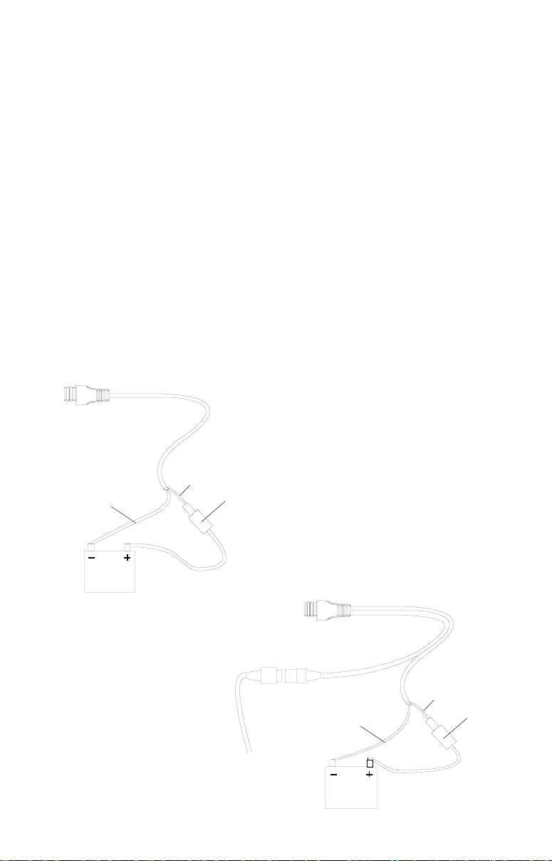
Power Connections - All Units
This unit works from a twelve-volt battery system. For the best results,
attach the power cable directly to the battery. You can attach the power
cable to an accessory or power buss, however you may have problems
with electrical interference. Therefore, it’s safer to go ahead and attach
the power cable directly to the battery. If the cable is not long enough,
splice #18 gauge wire onto it. The power cable has two wires, red and
black. Red is the positive lead, black is negative or ground. Make certain
to attach the in-line fuse holder to the red lead as close to the power
source as possible. F or example, if y ou have to e xtend the power cab le to
the battery or power buss, attach one end of the fuse holder directly to the
battery or power buss. This will protect both the unit and the power cable
in the event of a short. Use a 3-amp fuse .
IMPORTANT!
Do not use this product without a 3-amp fuse wired into the power cable!
Failure to use a 3-amp fuse will v oid y our w arranty.
AccuMap
POWER CONNCECTIONS
RED
BLACK
3-AMP
FUSE
12-VOLT
BA TTERY
TO
TRANSDUCER
UltraMap
POWER CONNCECTIONS
RED
BLACK
12-VOL T
BA TTERY
2
3-AMP
FUSE
Page 9
If possible, route the unit’s power cable and transducer cable away from
other wiring. VHF radio antenna cables radiate noise when transmitting,
so be certain to keep the sonar’s wires away from it. You may need to
route the sonar unit’s po wer cab le directly to the battery to isolate it from
other wiring on the boat.
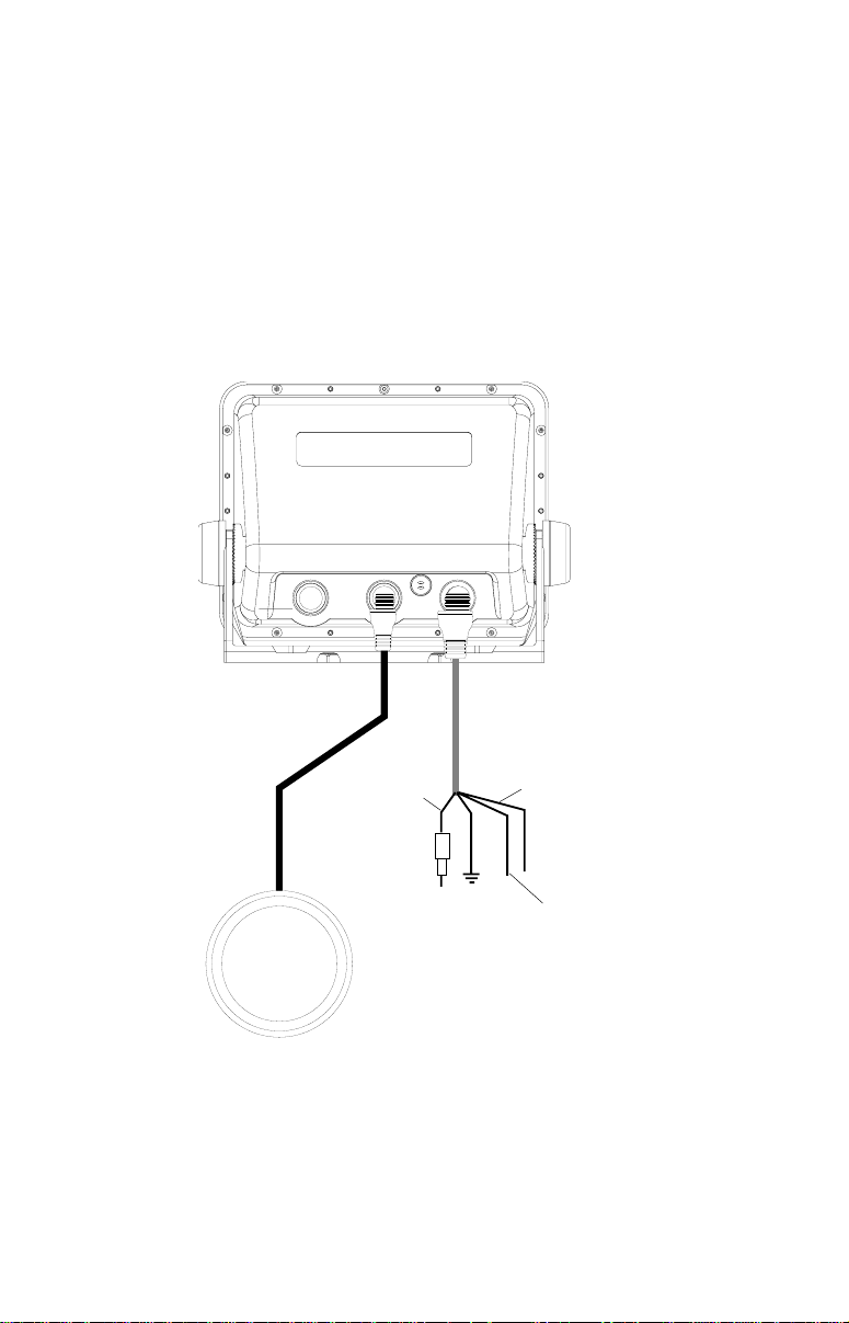
CABLE CONNECTIONS - AccuMap Only
EAGLE
ANTENNA
RED
(+12
VDC)
3
BLACK
(GROUND)
GREEN
(NMEA
RECEIVE)
WHITE
(NMEA
TRANSMIT)
Page 10
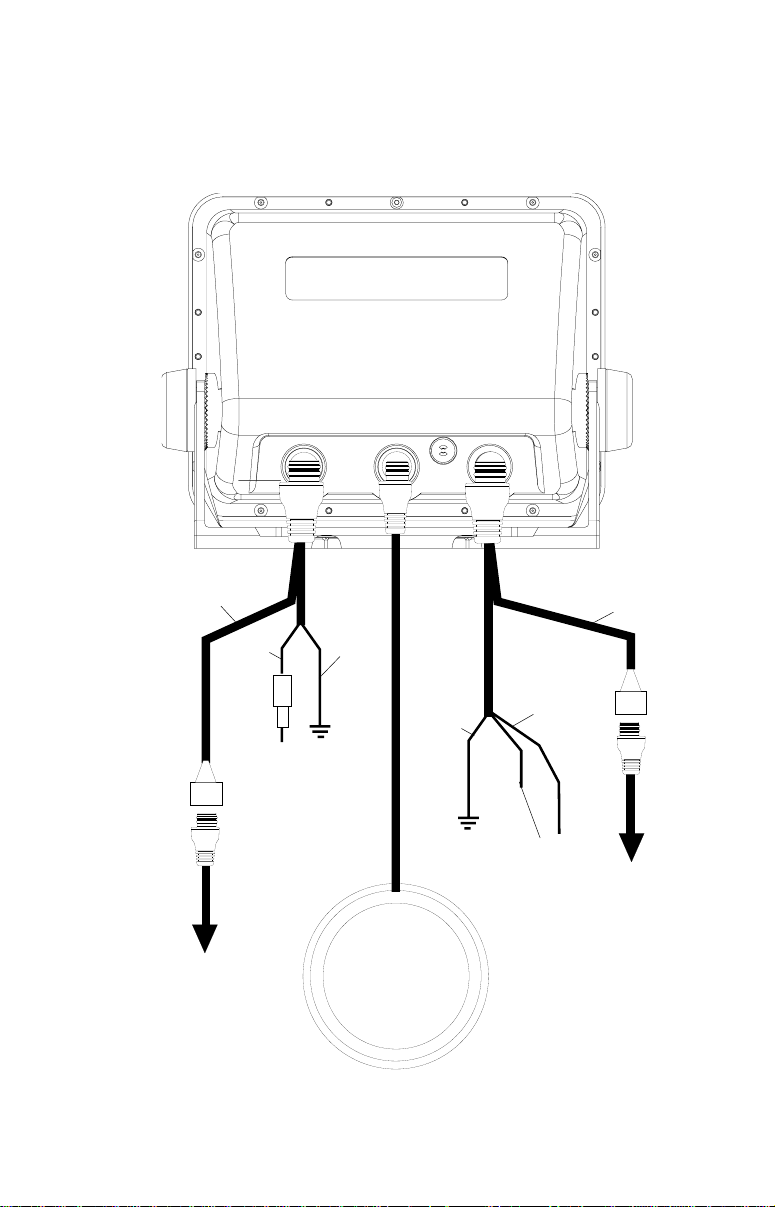
CABLE CONNECTIONS - ULTRAMAP Only
EAGLE
POWER/
TRANSDUCER
CABLE
TO
TRANSDUCER
RED
+12 VDC
BLACK
(GROUND)
BLACK
TO
ANTENNA
See Note 1
GREEN
(NMEA
RECEIVE)
WHITE
(NMEA
TRANSMIT)
NMEA
ADAPTER
CABLE
TO
SPEED/TEMP
SENSOR
(OPTIONAL)
Notes
1. If the NMEA wires are not used, then the NMEA adapter cable is not required. The
speed/temperature sensor's cable can be attached directly to the UltraMap.
4
Page 11

GPS Antenna Installation - All Units
The antenna can be mounted on any flat surface , provided y ou ha v e access behind the surface for the mounting screws. A magnet is also supplied that can be epoxied to the bottom of the antenna. A pole mount
adapter lets you mount the antenna on a pole or swivel mount that uses
standard 1" - 14 threads. The antenna has 25 feet of cable. Do not cut or
splice this cable.
Surface Mount
The antenna can be easily installed on any flat surface that is at least 90
mm (3 1/2") wide. Make certain that a clear view of the sky is av ailable at
the selected location. Since the GPS signals travel “line-of-sight”, nearly
anything blocking the antenna can potentially obstruct the unit from finding a satellite. Do not mount it in front of radar antennas. The y radiate high
energy that can interfere with the GPS signal.
Once you’ve determined the mounting location, use the template on page
51 in this manual to drill the holes for the screws. The screws, supplied
with this antenna, are 4mm x 30mm. (about 1 1/8" long). Drill 4.75 mm (3/
16") holes for the mounting screws. If you route the cable through the
mounting surface, y ou’ll need to drill a 25 mm (1") hole f or the cable .
There is a notch in the antenna housing that allows the cable to pass
through to the outside, instead of routing it through the mounting surface.
After drilling the holes, pass the o-ring over the antenna cable and press
it into the groove on the bottom of the antenna housing. Now attach the
antenna to the mounting surface, using 4mm screws and the supplied
lock washers. Route the cable to the GPS receiver and the antenna installation is finished.
5
Page 12

Magnet Mount
A magnet lets you temporarily mount the antenna on any ferrous metal surf ace. (such as a
car) To use the magnet, simply epoxy it to the
bottom of the antenna, using the epoxy supplied with your antenna. Carefully follow the instructions on the epoxy package and apply it
to the magnet. Then carefully press the magnet to the bottom of the antenna housing. After
the epoxy cures (in about 30 minutes), the antenna is ready for use.
Pole Mount
The antenna attaches to the pole mount adapter
with the supplied 4 mm screws. You can route
the antenna cable through the slot in the side of
the antenna, or pass it down through the pole
mount adapter. A slot next to the threads in the
pole mount adapter places the cable next to the
pole where it can be easily routed down the pole
to the GPS receiver. The threads on the pole
mount adapter accept a standard marine antenna
mount.
MAGNET
POLE MOUNT
SPEED/TEMPERA TURE SENSOR (UltraMap Onl y)
If you’re installing a temperature or speed/temperature sensor, read the
sensor’s mounting instructions before making the installation. Route the
sensor’s cable directly to the UltraMap and plug it into the connector on
the NMEA/DGPS cable.
TRANSDUCER INST ALLATION (UltraMap Only)
The HS-WSBK supplied with this unit is a transom mount transducer. It
can be installed on any outboard or stern-drive (inboard\outboard) powered boat. It can also be permanently installed inside the boat to “shootthrough” the hull on some fiberglass boats.
The “kick-up” mounting bracket helps prevent damage if the transducer
strikes an object while the boat is moving. If the transducer does “kickup”, the bracket can easily be pushed bac k in place without tools .
6
Page 13
Read this section carefully before attempting the installation. Determine
which of the mounting positions is right for your boat. Remember, the
transducer location is the most critical part of a sonar installation.
Location - General
1. The transducer must be placed in a location that has a smooth flow of
water at all times. If the transducer is not placed in a smooth flow of
water, interference will show on the sonar’s display in the form of random lines or dots whenever the boat is mo ving.
2. The transducer should be installed with it’s f ace pointing straight down,
if possible.
3. Make certain the transducer’s location doesn’t interfere with the trailer
or hauling of the boat. Also, don’t mount it closer than approximately
one foot from the engine’ s low er unit. This will prevent cavitation interference with the propeller . Typically , the transducer should be mounted
as deep in the water as possible. This increases the chance that it will
be in the water in high speed and reduces the possiblity of air bubble
interference.
POOR LOCATIONPOOR LOCATION
POOR LOCATION
POOR LOCATIONPOOR LOCATION
POOR ANGLEPOOR ANGLE
POOR ANGLE
POOR ANGLEPOOR ANGLE
GOOD LOCATIONGOOD LOCATION
GOOD LOCATION
GOOD LOCATIONGOOD LOCATION
4. If possible, route the transducer cable away from other wiring on the
boat. Electrical interference from VHF radio , engine wiring, bilge pumps,
and areators can be displayed on the sonar’ s screen. Use caution when
routing the transducer cable around these wires.
CAUTION!CAUTION!
CAUTION!
CLAMP THE TRANSDUCER CABLE TOCLAMP THE TRANSDUCER CABLE TO
CLAMP THE TRANSDUCER CABLE TO
CLAMP THE TRANSDUCER CABLE TOCLAMP THE TRANSDUCER CABLE TO
TRANSOM NEAR THE TRANSDUCER. THISTRANSOM NEAR THE TRANSDUCER. THIS
TRANSOM NEAR THE TRANSDUCER. THIS
TRANSOM NEAR THE TRANSDUCER. THISTRANSOM NEAR THE TRANSDUCER. THIS
WILL HELP PREVENT THE TRANSDUCERWILL HELP PREVENT THE TRANSDUCER
WILL HELP PREVENT THE TRANSDUCER
WILL HELP PREVENT THE TRANSDUCERWILL HELP PREVENT THE TRANSDUCER
FROM ENTERING THE BOAT IF IT ISFROM ENTERING THE BOAT IF IT IS
FROM ENTERING THE BOAT IF IT IS
FROM ENTERING THE BOAT IF IT ISFROM ENTERING THE BOAT IF IT IS
KNOCKED OFF AT HIGH SPEED.KNOCKED OFF AT HIGH SPEED.
KNOCKED OFF AT HIGH SPEED.
KNOCKED OFF AT HIGH SPEED.KNOCKED OFF AT HIGH SPEED.
CAUTION!CAUTION!
GOOD LOCATIONGOOD LOCATION
GOOD LOCATION
GOOD LOCATIONGOOD LOCATION
7
Page 14
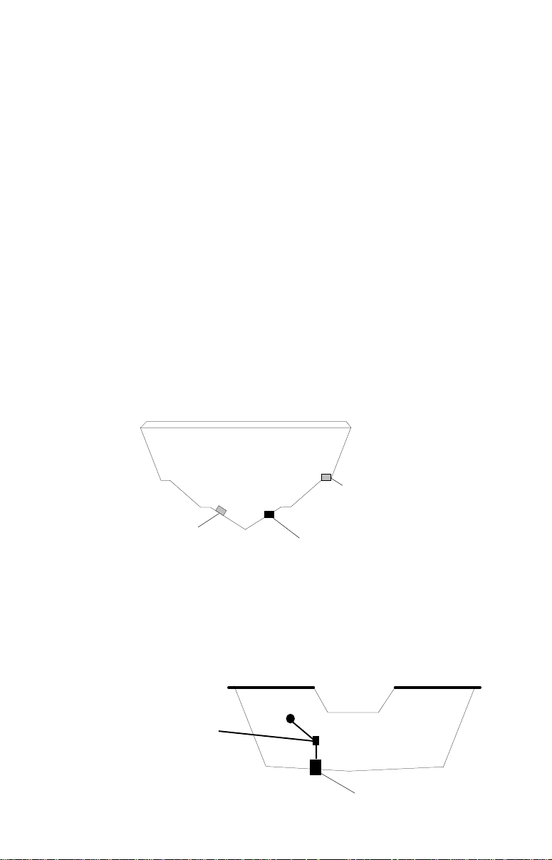
T ransducer Assembl y and Mounting
The best way to install this transducer is to loosely assemble all of the
parts first, then place the transducer’s bracket against the transom and
see if you can mov e the transducer so that it’s parallel with the ground.
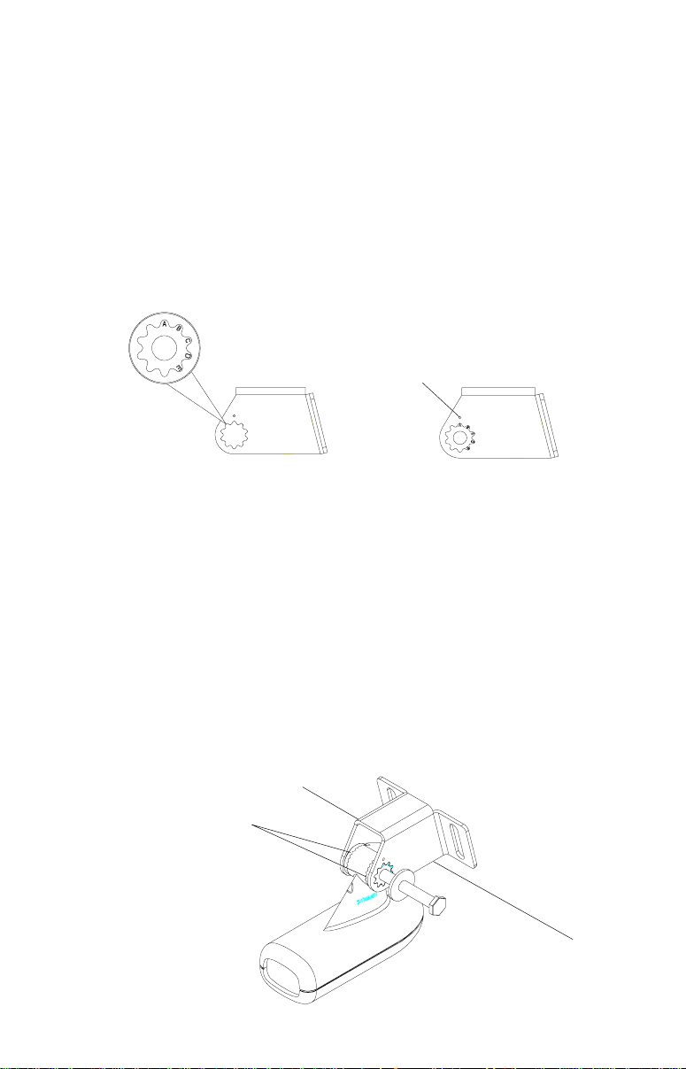
1. Press the two small plastic ratchets into the sides of the metal bracket
as shown below . Notice there are letters molded into each ratchet. Place
each ratchet into the bracket with the letter “A” aligned with the dot
stamped into the metal bracket. This position sets the transducer’s
coarse angle adjustment for a f ourteen (14) degree transom. Most outboard and stern-drive transoms have a f ourteen degree angle.
DOT
2. Slide the transducer between the two ratchets. Temporally slide the bolt
though the transducer assembly and hold it against the transom. Looking at the transducer from the side, check to see if it will adjust so that
its face is parallel to the ground. If it does, then the “A” position is correct for your hull. If the transducer’s face isn’t parallel with the g round,
remove the transducer and ratchets from the br ack et. Place the ratchets into the holes in the bracket with the letter “B” aligned with the dot
stamped in the bracket. Reassemble the transducer and bracket and
place them against the transom. Again, check to see if you can move
the transducer so it’s par allel with the ground. If it does, then go to step
3. If it doesn’t, repeat step 2, but use a different letter until you can
place the transducer on the transom correctly.
RATCHETS
8
Page 15
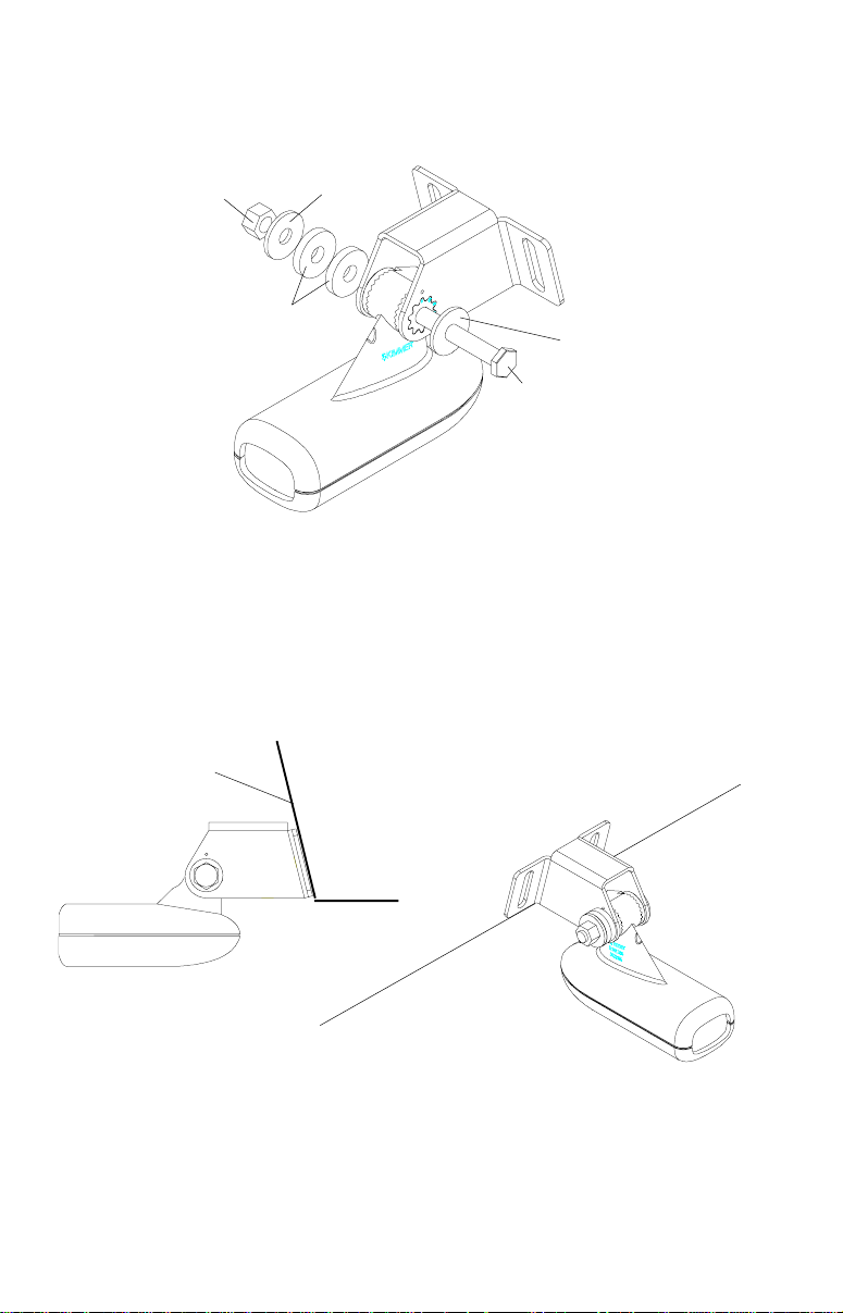
3. Once you determine the correct position for the ratchets, assemble the
transducer as shown below. Don’t tighten the lock nut at this time.
METAL
NUT
WASHER
RUBBER
WASHERS
BOLT
METAL
WASHER
4. Hold the transducer and bracket assembly against the transom. The
transducer should be roughly parallel to the ground. The bottom of the
transducer bracket should be in line with the bottom of the hull. Don’t let
the bracket extend below the hull! Mark the center of the slots for the
mounting holes. Drill two 5/32" holes in the marked locations for the
#10 screws supplied with the transducer .
TRANSOM
SIDE VIEW
5. Attach the transducer to the transom. Slide the transducer up or do wn
until it’s aligned properly on the transom as shown abo ve. Tighten the
bracket’ s mounting scre ws. Adjust the tr ansducer so that it’s par allel to
the ground and tighten the lock nut until it touches the flat washer , then
add 1/4 turn. Don’t over tighten the lock nut! If you do, the transducer
won’t “kic k-up” if it strikes an object in the water.
9
Page 16

6. Route the transducer cable to the sonar unit. If possib le, route the transducer cable away from other wir ing on the boat. Electrical noise from
the engine’s wiring, bilge pumps, VHF radio wires and cables, and aerators can be picked up by the sonar . Use caution when routing the transducer cable around these wires.
IMPORTANT!
Clamp the transducer cable to the transom close to the transducer. This
can prevent the transducer from entering the boat if it is knocked off at
high speed.
7. Make a test run to determine the results. If the bottom is lost at high
speed, or if noise appears on the display, try sliding the transducer
bracket do wn. This puts the transducer deeper into the w ater, hopefully
below the turbulence causing the noise. Don’t allow the transducer
bracket to go belo w the bottom of the hull!
Periodically wash the transducer’s face with soap and water to remove
any oil film that may collect. Oil and dirt on the face will reduce the sensitivity or may e v en pre v ent oper ation.
INTRODUCTION T O GPS
The Global Positioning System (GPS) w as developed by the United States
Department of Defense as a 24-hour a day, 365 days a year global navigation system for the military . Civilian availability was added (b ut with less
accuracy) using the same satellites. T w enty-four satellites orbit the Earth.
Three of these satellites are spares, unused until needed. The rest virtually guarantee that at least four satellites are in vie w nearly anywhere on
Earth at all times.
The system requires three satellites in order to determine a position. This
is called a 2D fix. It takes four satellites to determine both position and
elevation, (y our height abov e sea le v el - also called altitude.) called a 3D
fix.
Remember, the unit must have a clear view of the satellites in order to
receive their signals. Unlike radio or television, GPS works at very high
frequencies. The signals can be blocked easily by trees, buildings, even
your body.
Never use this GPS receiv er while oper ating a v ehicle!
Like most GPS receivers, this unit doesn’t have a compass or any other
navigation aid built inside. It relies solely on the signals from the satellites
10
Page 17

to calculate a position. Speed, direction of travel, and distance are all
calculated from position information. Theref ore, in order for it to determine
direction of travel, you must be moving and the faster, the better. This is
not to say that it won’t work at trolling speeds - it will. There will simply be
more “wandering” of the data sho wn on the displa y.
Another factor that greatly influences the receiver’s ability to deter mine
position is SA. The United States government intentionally degrades the
satellite’s signal for civilian users. They introduce small errors into the
signals that makes the GPS receiver less accurate. These errors are called
selective av ailability, or SA. How bad is it? They guarantee that the position reported by a GPS receiver that meets their specifications is within
100 meters horizontally and 150 meters vertically 95% of the time. (The
position can be worse than that the other 5% of the time.) In other words,
the position shown on your receiver is within 100 meters of your actual
position, 95% of the time. That’ s ov er 300 feet! Not e xactly pinpoint accuracy, but then few people need positioning accuracy greater than this.
However, if you do want better performance, (and who doesn’t?) many
manufacturers (including Eagle) sell a DGPS receiver that attaches to
your GPS receiver. The DGPS system transmits correction signals that
nullify the effects of SA. The DGPS receiver takes signals from these
land-based transmitters and gives them to the GPS receiver which then
uses them to show a more accurate position. The ironic part is the federal
government implemented SA and is also operating many DGPS transmitters. (You can use the signals from all of the Coast Guard DGPS stations
for free, by the way.) The downside to this is it requires another piece of
electronic gear (the DGPS receiver) . And you hav e to be close enough to
a station to receive the DGPS signals.
Generally, you find that using your GPS receiver without DGPS is both
easy and amazingly accurate. It’s easily the most accurate method of
electronic navigation available to the general public today. Remember,
however, that this receiver is only a tool. Alw a ys ha v e another method of
navigation av ailab le , such as a chart or map and a compass.
Also remember that this unit will always show navigation information in
the shortest line from your present position to a waypoint, regardless of
terrain! It only calculates position, it can’t know what’s between you and
your camp, f or example. It’ s up to you to saf ely navigate around obstacles,
no matter how you’re using this product.
11
Page 18
GPS OPERATION
There are 12 keys on the ke yboard. You can navigate through the menus ,
adjust the chart’s cursor, and enter data using the arrow keys. The five
major modes of operation are accessed using the PAGES key. Press the
MENU key to select or adjust a feature from a list. The Z-IN and Z-OUT
keys zoom-in or zoom-out the view on the plotter screen. The ENT and
EXIT keys are used to enter or clear data or screens. Save and edit
waypoints using the WPT key. The PWR key turns the unit on and off.
Pressing it once while the unit is operating turns on the screen’s backlight. To prevent an accidental shutdown, you must hold the PWR key
down for a f e w seconds to turn the unit off .
ZIN
ZOUT
PAGES WPT
MENU EXIT
PWRENT
Most of the unit’s f eatures are f ound on “men us’. Y ou can view the men us
by pressing the MENU key. This product has “Intelligent Menus”. There
are many menus that pertain to only the sonar, for example. When you
press the MENU key and the sonar is showing, men u items for the sonar
show in addition to the normal menus. F or example , if the sonar is showing, and you press the MENU key, GPS map items won’t show on the list.
This helps you find the needed item without scrolling through unnecessary menus.
12
Page 19
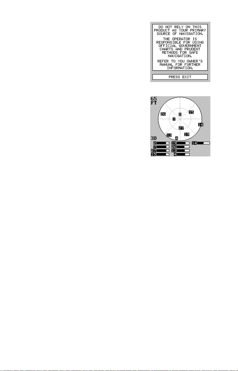
To turn the unit on, simply press the PWR key . A
GPS logo screen appears, then the screen similar to the one at right appears. Read the message on the screen, then press the EXIT key to
erase it or wait a few seconds and it automatically clears. The screen shown below appears
next.
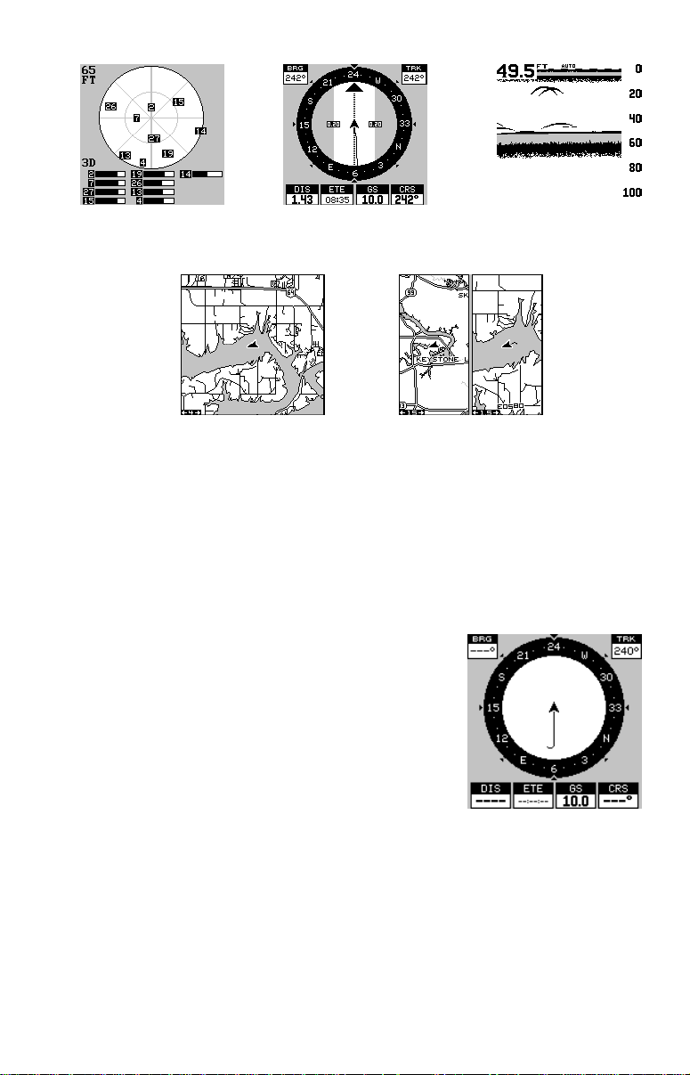
This screen appears each time you turn the unit
on. It shows a graphical view of the satellites that
are in view. Each satellite is shown on the circular chart relative to your position. The point in the
center of the chart is directly overhead. The small
inner ring represents 45° above the horizon and
the large ring represents the horizon. North is at
the top of the screen. You can use this to see
which satellites are obstructed by obstacles in
your immediate area if you hold the unit facing
north.
The GPS receiver is tracking satellites that are surrounded by a black
box. The receiver hasn't locked onto a satellite if it's number isn't surrounded by a box, theref ore it isn’t being used to solv e the position.
Beneath the circular graph are the bar graphs, one for each satellite in
view . Since the unit has twelv e channels, it can dedicate one channel per
visible satellite. Therefore, if only six satellites are visible, only six bar
charts show at the bottom of the screen. The wider the bar on the gr aph,
the better the unit is receiving the signals from the satellite.
The number in the upper left corner is the “expected horizontal position
error” or e xpected error from a benchmark location. In other words , if the
expected error shows 50 f eet, then the position sho wn by the unit is estimated to be within 50 feet of the actual location. Ho we v er , this n umber is
only valid if you’re using DGPS or if S/A is tur ned off. Due to S/A, the
accuracy can only be less than 100 meters, 95% of the time, per U.S.
government specifications. Although the expected error is not accurate
unless you hav e a DGPS receiv er, it does give you an indicator of the fix
quality the unit currently has. The smaller the expected error n umber , the
better (and more accurate) the fix is. If the expected error flashes, then
the unit hasn't locked onto the satellites , and the number shown isn't valid.
A light bulb indicator at the top right corner of the screen appears when
the backlights are on.
13
Page 20

FINDING Y OUR POSITION
Auto Search
To lock onto the satellites, the GPS receiver needs to know it’s current
position, UTC time, and date. (Elev ation (altitude) is also used in the equation, but it’ s rarely required to determine a position.) It needs this data so
that it can calculate which satellites should be in view . It then searches for
only those satellites. When your GPS receiver is turned on for the first
time, it doesn’t know what your position or elevation (altitude) is. It does
know the current UTC time and date since these were programmed into it
at the factory and an internal clock keeps the time while the unit is turned
off. It begins searching for the satellites using the above data that it acquired the last time it was turned on. This probably was at the factory.
Since it’s almost certain that you’ re not at our factory , it’ s probably looking
for the wrong satellites. If it doesn’t find the satellites it’s looking for after
five minutes, it s witches to A uto Search. The receiver looks for any satellite in the sky. Due to advanced technology, the auto search time has
shrunk to about five minutes, so the longest time you should e ver ha ve to
wait is ten minutes from the time you turn the unit on until it locks onto the
satellites and shows a position. Once the unit locks onto the satellites, it
should take less than a minute to find your position the ne xt time it’s turned
on, provided you hav en’t moved more than appro ximately 100 miles from
the last location it was used.
Manual Initialization
If you don’t want to wait for the Auto Search, then you may be able to
speed up the initialization process by using the manual initialization f eature. Using this feature tells the unit it’ s approximate position. Once it knows
it’s location, it determines exactly which satellites should be in view and
starts looking only for those satellites.
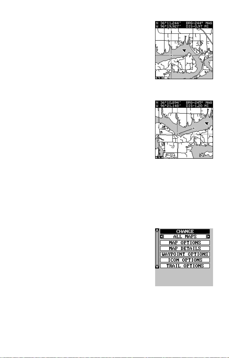
To manually initialize the unit, press the MENU
key . Now press the do wn arrow key until the “GPS
SETUP” label is highlighted. Press the right arrow key. The “INITIALIZE GPS” label is highlighted. Press the right arrow key again. A screen
similar to the one at right appears. Use the arrow
keys to mov e the crosshairs to your appro ximate
location on the map. You can use the ZIN and
ZOUT keys to enlarge the map which makes it
easier and faster to find your location. The box at the top of the screen
shows the latitude and longitude of the cursor position, along with the
distance and bearing from the last known position. Once you have the
crosshairs on your location, press the ENT key. The unit returns to the
satellite status screen.
14
Page 21

Using the manual initialization method loads a position that’s close to
yours into the GPS receiver. It should now have position, time , and date,
thereby giving it the data it needs to determine which satellites are in
view . Once the satellites are known, the receiver searches for only those
satellites, making a lock f aster than an auto search method.
All position and navigation data flashes until the unit acquires a position.
Do not rely on any data that is flashing! When the n umbers are flashing,
they represent the last known values when the unit lost it’s lock on the
satellites.
Position Aquisition
When the receiver locks onto the satellites and calculates a position, it
shows the message “P osition Acquired” on the screen. Once the unit has
acquired the satellites and the position acquired message appears, it’s
ready for use.
(Note: The altitude data may still flash even if the unit shows a “Position
Acquired” message and all other data is not flashing. The unit must be
locked onto at least f our satellites to determine altitude. It only tak es three
satellites to determine position. You can navigate with this unit if the altitude is flashing, simply ignore the altitude display until it quits flashing.)
REMEMBER, DO NOT NAVIGATE WITH THIS UNIT UNTIL THE NUMBERS STOP FLASHING!
MODES
The UltraMap has five modes: status, navigation, sonar, map, and window groups. The AccuMap has f our - no sonar mode. Use the P A GES and
arrow keys to s witch between the different screens . The four GPS screens
that show by default are shown at the top of the next page. (UltraMap
owners, see the sonar section in this manual for sonar operation.)
To change modes, simply press the P A GES ke y.
A screen similar to the one at right appears. Use
the up or down arrow ke ys to change modes. (The
windows mode is shown as “groups”. Group “A”
is the first windows group .)
Press the right arrow key while the above menu
is showing to switch between different versions
of each mode. When the desired screen appears,
press the EXIT key to erase the menu.
15
Page 22
STATUS NAVIGATION SONAR
MAPPING WINDOW GROUPS
(UltraMap Only)
Navigation
There are two different na vigation screens. Nav screen number one shows
a graphical view of your trip, Nav screen number 2 shows all navigation
details in large digital numbers. You can also customize both navigation
screens to show data other than the default. See the “Prog ramming Box es”
section for more information.
Nav-1
This screen has a compass rose that shows not
only your direction of travel, but also the direction to a recalled waypoint. The navigation screen
looks like the one at right when you’re not navigating to a waypoint. Your position is shown by
an arrow in the center of the screen. Your trail
history, or path you’ve taken is depicted by the
line extending from the arrow . The arro w pointing
down at the top of the compass rose indicates
the current track (direction of trav el) y ou are taking. This is also shown in
the “TRK” (track) box in the upper right corner of the screen. On the example shown at right, the track is 240°. The current ground speed (GS)
shows in the box in the lower center of this screen.
When navigating to a waypoint, Nav screen number one looks like the
one at the top of the next page. Bearing to the destination waypoint is in
the box in the upper left corner. Bearing is also shown by the large arrow
16
Page 23
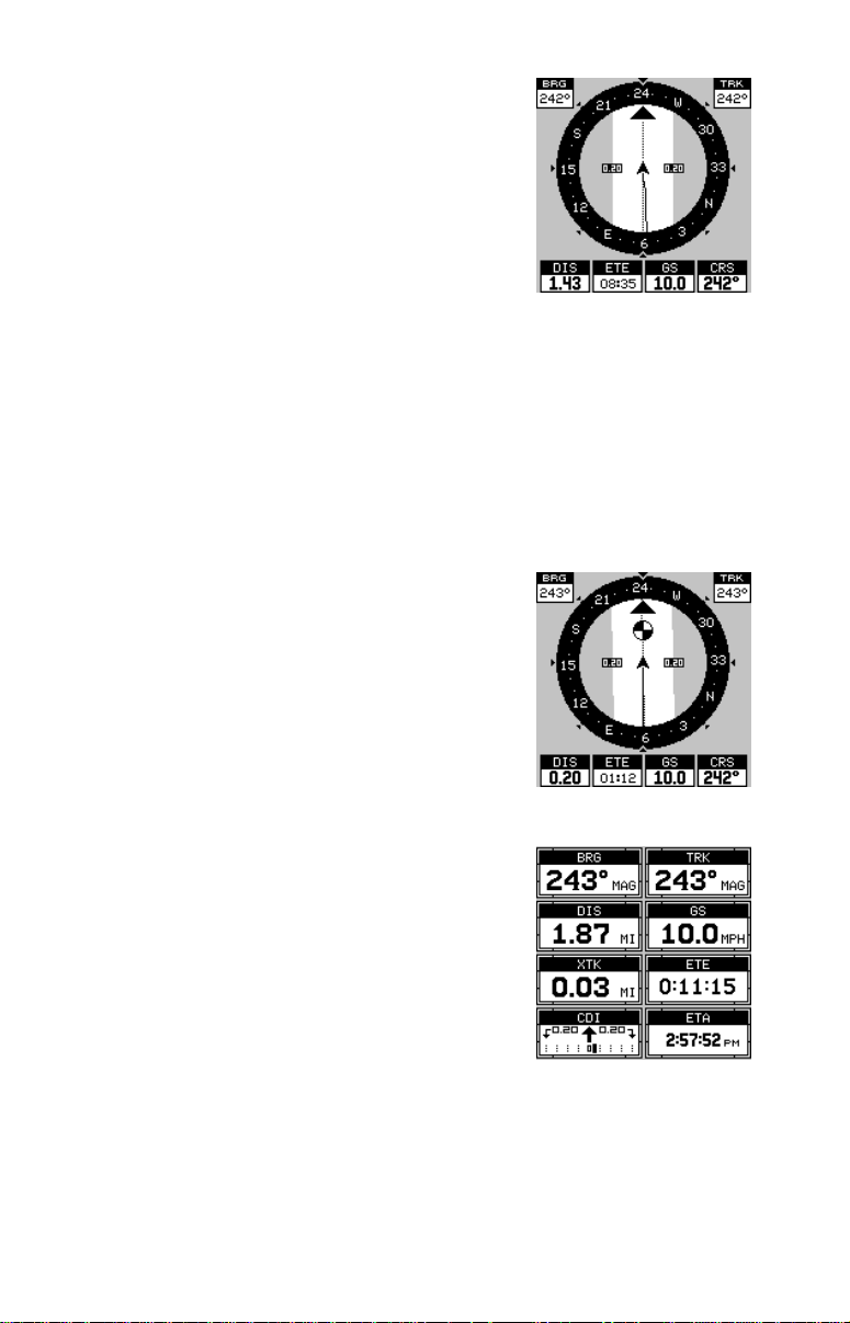
pointing up towards the compass, above the
present position arrow . Distance from the present
position to the waypoint (DIS) sho ws beneath the
compass on the lower left side of the screen. Next
to the distance box is estimated time enroute
(ETE). This is the estimated time that it will take
you to arrive at the destination, based upon current track and ground speed. In the lower right
corner is the course (CRS) box showing the direction from your starting position to the waypoint. Remember, a course
is a proposed path from the starting position to the destination. Track is
your actual direction of trav el.
Lines on either side of the present position show the current cross track
error range. Cross track error is the distance you are off-course to the
side of the desired course line. The course line is an imaginary line draw n
from your position when you started navigating to the destination waypoint. It’s sho wn on the screen as a vertical dotted line. The default f or the
cross track error range is 0.20 mile . F or example,
if the present position symbol touches the right
cross track error line, then y ou are .25 mile to the
right of the desired course. You need to steer left
to return to the desired course. You can use the
ZIN or ZOUT keys to change the cross tr ac k error range. A circle depicting your destination (wa ypoint) appears on the screen as you approach
the waypoint as shown on the screen at right.
Nav-2
This navigation screen shows all navigation information in large digital numbers. To view this
screen, press the PAGES key, then press the up
arrow key until the “NAV 1” label is highlighted.
While it’s highlighted, press the right arrow key.
The screen shown at right appears. Press the
EXIT key to erase the menu.
This screen is composed of eight digital boxes.
Track (TRK) and ground speed (GS) data are the only ones that show
data if you’ re not navigating to a w a ypoint. If y ou are navigating to a w a ypoint, then bearing (BRG), distance to waypoint (DIS), estimated time en
route (ETE), cross track error (XTK), estimated time of arrival (ETA), and
the CDI also operate.
17
Page 24
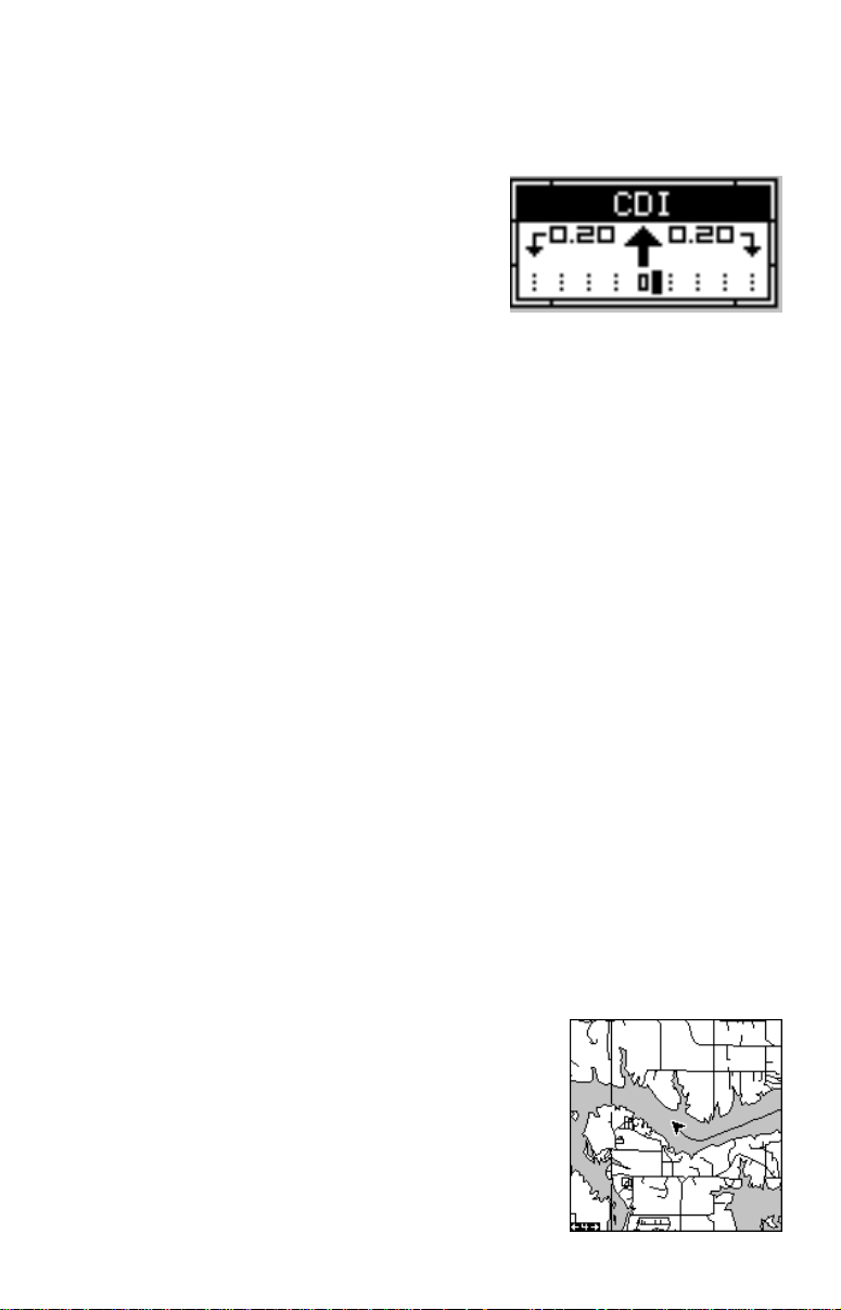
Course Deviation Indicator (CDI)
Once navigation to a waypoint is established, the CDI shows your distance to the left or right of the desired course. The vertical line in the box
shows both the direction you must steer to
get back on course and the distance to the
course line. For example, if you’re travelling straight towards the destination, from
the start, then the line stays in the center.
If you drift off course to the right, the line
moves to the left. This signifies that you
need to steer to the left to get back on course. This is called “chasing the
needle”. If you steer towards the line (needle), you’ll alw ays be heading in
the correct direction to get back on course.
The CDI’s range sho ws beneath the CDI label. On the abo ve screen, the
CDI range is .20 mile, which is the default. You can adjust the range by
selecting “ALARMS” on the main menu, then “GPS ALARMS”. Highlight
the “CDI DIS” label, then use the left or right arrow key to adjust it. The
CDI range is also shown by the dotted lines at the f ar left and right side of
the CDI indicator. If the solid line is on either of the dotted lines, then you
are 0.20 mile off course. Remember, if the line mo ves to the left, then y ou
are too far to the right of the desired course line and vice-versa.
Using the CDI with a mapping screen helps you visualize your position in
relation to the course. The screen on the right shows that we are off course
to the right. The vertical bar has mov ed to the left side of the CDI, showing
the direction to the desired course line. The CDI giv es you a quick, easy to
read visual indicator of your relationship between your direction of tra v el
and the desired direction.
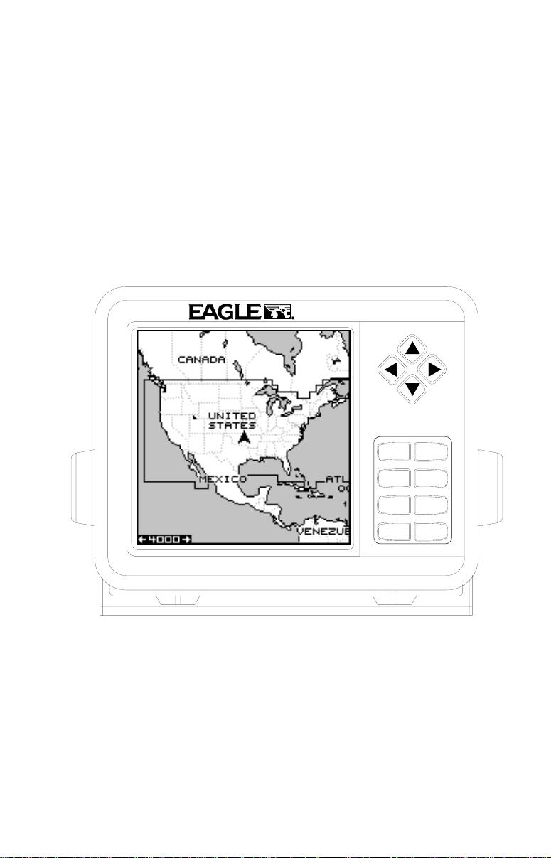
Map
This unit has a ground map of the world built inside. This map has the
majority of its detail in far southern Canada, the continental United States
and Hawaiian islands, northern Mexico, the Bahamas, and Bermuda. The
map screens show your course and track from a “birds-eye” view . If you’ re
navigating to a waypoint, the map shows your
starting location, present position, course line,
and destination. You don’t have to navigate to a
waypoint, ho we ver, to use the map.
Using the map is as simple as pressing the
PAGES key, then highlighting “MAP 1”. A screen
similar to the one at right appears. The arrow
flashing in the center of the screen is your present
18
Page 25
position. It points in the direction y ou’ re travelling. The solid line extending
from the arrow is your plot trail, or path y ou’ve taken. The plotter’s range
shows in the lower left corner of the screen. In this e xample, the plotter’s
range is four miles from the left edge of the map to the right.
MAP-1 MAP-2 MAP-3
There are three different mapping screens. T o vie w the other map screens,
press the PAGES key, highlight the MAP label, and press the right arrow
key until the desired map screen appears. Press the EXIT key to erase
the menu. Map-2 has navigation data added at the right side. The data
includes bearing to waypoint (BRG), track (TRK), distance to waypoint
(DIS), ground speed (GS), a steering arrow (shows the direction to the
destination when the top of the screen is pointing in your direction of
travel), and a CDI.
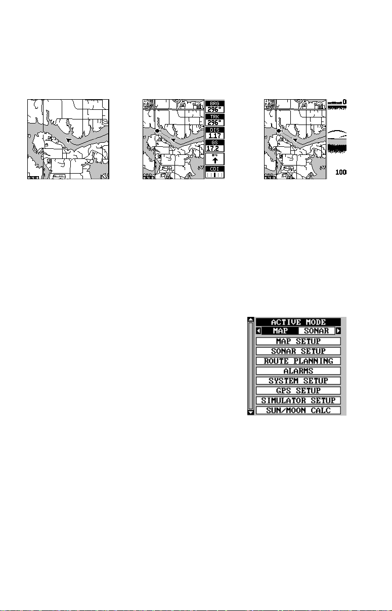
Map-3 is similar to Map-2, except it shows sonar
data on the right side. When the MENU key is
pressed while Map-3 is showing, the screen
shown at right appears. The "ACTIVE MODE"
menu at the top of this screen lets you switch the
arrow and zoom ke ys between the GPS side and
the sonar side of Map-3.
The Z-IN and Z-OUT keys zoom-in and out all
maps to enlarge or reduce their coverage area. The av ailable ranges are:
0.1, 0.15, 0.2, 0.3, 0.4, 0.6, 0.8, 1, 1.5, 2, 3, 4, 5, 6, 8, 10, 15, 20, 30, 40,
60, 80, 100, 150, 200, 300, 400, 600, 800, 1000, 1500, 2000, 3000, and
4000 miles.
Cursor
Pressing an arrow key turns on two dotted lines that intersect at the present
position symbol. These lines are called a “cursor” and have a variety of
uses.
T o turn the cursor on, simply press the arrow k ey in the direction you want
the cursor to move. This lets you view areas on the plotter that are a w ay
19
Page 26
from your present position. The zoom-in and
zoom-out keys work from the cursor’s position
when it’s active - not the present position. You
can zoom in on any detail, anywhere. The cursor
can also place icons and waypoints .
When the cursor is used with map-1, it’s position, bearing, and distance from your present
position show at the top of the screen.
Cursor Distance
You can use the cursor to find the distance between two points. While the cursor is showing,
press the MENU key, then select "FIND DIST ANCE". The unit returns to the mapping screen.
Now move the cursor to the first location that y ou
want to measure the distance from and press the
ENT key. Now move the cursor to the position
that you want to measure the distance to. A line
is drawn from the point when the ENT key was
pressed to the cursor's present location. The distance cov ered by the line
shows at the top of the screen. To measure another two points, simply
move the cursor and press the ENT k e y.
Press the EXIT key to erase the cursor. The unit centers your present
position on the screen after erasing the cursor .
MAP SETUP
The map has many customization options. To
change them, first press the MENU key while a
map is showing on the screen. The map setup
label is highlighted. Press the right arrow key. A
screen similar to the one at right appears.
Change Maps
Changes made to the map using the options in
the Map Setup is normally made to all map
screens. The change can be limited to the map screen currently in use,
howev er , by switching the “All Maps” to “This Map” in the “Change” menu.
To do this, simply highlight the “Change” label, then press the right arrow
key. T o s witch bac k, repeat the abo ve.
20
Page 27
Map Options
The following map options are listed under the “Map Options” menu: Map
Orientation, Auto Zoom, Range Rings, and Latitude/Longitude Grids.
Map Orientation
By default, this receiver sho ws the map with north always at the top of the
screen. This is the way most maps and charts are printed on paper. This
is fine if you’ re alw a ys tra v elling due north. What you see to your left corresponds to the left side of the map, to your right is shown on the right
side of the map, and so on. Ho we ver , if y ou tra vel an y other direction, the
map doesn’t line up with your view of the world.
To correct this problem, a track-up mode rotates the map as you turn.
Thus, what you see on the left side of the screen should alw ays be to your
left, and so on. A course-up mode keeps the map at the same orientation
as the initial bearing to the waypoint.
NORTH-UP TRACK-UP COURSE-UP
In the north-up view shown at left, we’re travelling east. In this view, the
present position indicator appears to move towards the right side of the
screen.
In the track-up view, the present position moves straight towards the top
of the display. A “N” shows to help you see which direction is north when
the track-up mode is on. Remember, in the track-up mode, the screen
rotates as you change direction. It always keeps your direction of travel
(track) heading towards the top of the screen.
In the course-up mode, the screen is locked into y our original bearing to
the recalled waypoint, regardless of your tr ac k.
To select the desired mode, first press the MENU key, select “MAP 1
SETUP”, then select “MAP OPTIONS”. Finally, select “ORIENTATION”
and press the right or left arrow key until the desired mode appears. Press
the EXIT key to erase this men u.
21
Page 28
Range Rings/Grid Lines
The map screen can be customized with rings
that are 1/4 of the range and/or grids that divide
the plotter into equal segments of latitude and
longitude. To do this, press the MENU key, select
“Map 1 Setup”, then “Map Options”. Highlight the
desired option, then press the right arrow key to
turn it on. Press the EXIT ke y repeatedly to erase
the menus. The screen at right shows grids.
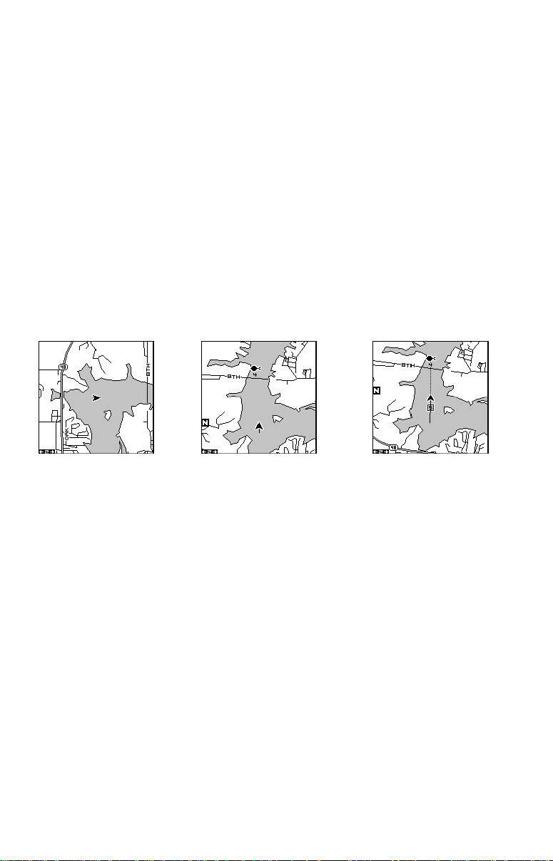
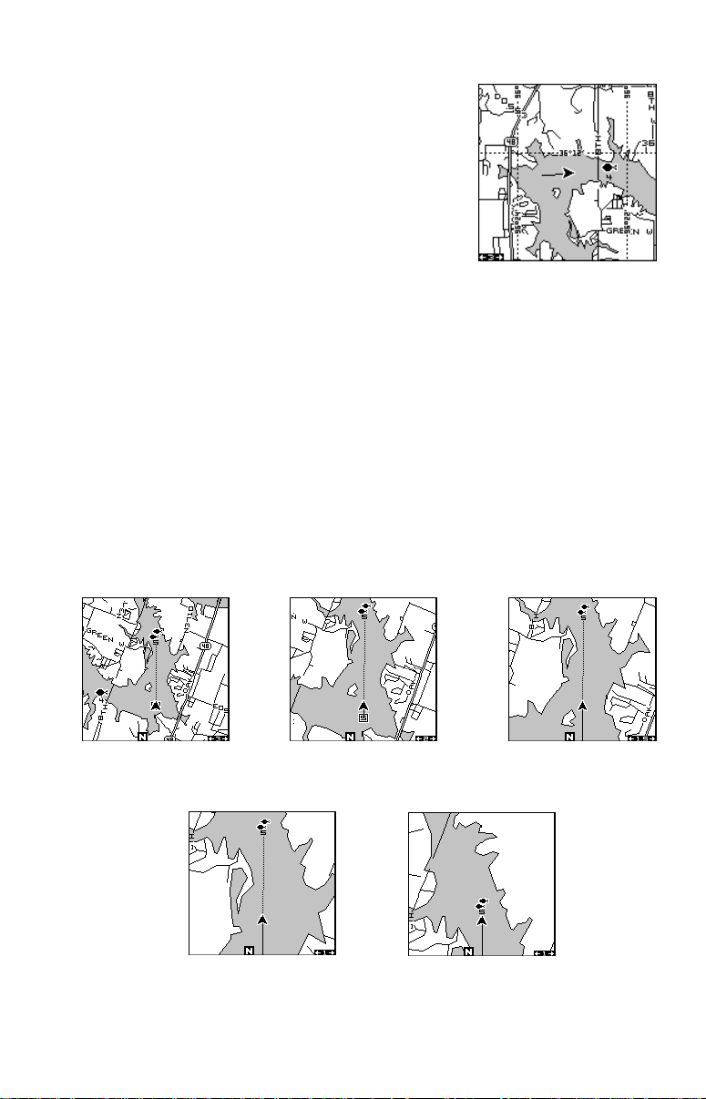
AUTOZOOM
This receiver has an autozoom f eature that eliminates much of the button
pushing that competitive units force you to make. It works in conjunction
with the navigation features. First, recall a waypoint. (See the waypoint
section for more information on navigating to a w a ypoint.) Then, with the
autozoom mode on, the unit zooms out until the entire course shows,
from the present position to the destination waypoint (recalled wa ypoint).
As you trav el towards the destination, the unit automatically begins zooming in, one zoom range at a time, keeping the destination on the screen.
The screens below show a slice of the progression of a trip near a lake.
Screen number one is the start and is on the 3 mile range. Intermediate
stages progressively zoom in as it gets closer to the destination.
12 3
4
22
5
Page 29

MAP DET AILS
This unit lets you change many of the built-in
background map’s features. To change the options, first press the MENU key, then select the
Map Details label. Press the right arrow key. The
screen shown at right appears.
Earth Map On/Off
The map can be turned on or off using the “All
Map Details” label. Simply highlight the menu, then press the left arrow
key to turn it off.
EARTH MAP ON
EARTH MAP OFF
T ext Labels
Select “Map Text” to turn all names on the map (such as Lake Tahoe or
Mississippi River) off or on. The def ault is “on”. Press the left arrow key to
turn them off.
Map Detail
The detail shown on the background map diminishes as the screen is
zoomed out. This prevents cluttering of the display, or overlapping of text
and graphics which can make it unreadable. There are two detail levels:
normal and high. The difference between the two shows belo w. The screen
on the left is normal detail, on the right is high detail. Both screens are on
the 10 mile range.
NORMAL DETAIL
HIGH DETAIL
To change the map’s detail setting, select “Map Detail Level” from the
map details menu, then press the right arrow key.
23
Page 30

Gray Fill
When this unit is first turned on, all water (lakes, oceans, rivers) is filled
with gray to distinguish it from land, which is clear. (See below) To make
the land fill with gray and water remain clear, select the “Fill with Gray”
label from the Map Detail menu, then press the left arrow key. Press the
EXIT key repeatedly to return to the mapping screen.
WATER FILLED
WITH GRAY
LAND FILLED
WITH GRAY
Map Boundaries
By default, this unit dra ws a line around areas of the map that hav e more
detail than the background map. This line depicts the detailled map boundaries. To turn this off, select “Map Bounds” from the map details menu,
then press the left arrow ke y.
Map Symbols
When the nav aid data is downloaded to this unit, buo ys and other navigational aids can be turned off or on by using “Map Symbols” on the “Map
Details” menu. To find this menu, press the down arrow key while on the
“Map Details” menu until “Map Symbols” appears . Press the left arrow k ey
to turn them off.
LIGHTED BUOY
UNLIGHTED BUOY
LIGHT
SQUARE DAYBEACON
TRIANGLE DAYBEACON
RADIO BEACON
PLATFORM
INTERSTATE HIGHWAY
U.S. ROUTE HIGHWAY
U.S. ALTERNATE ROUTE HWY.
STATE HIGHWAY
COUNTY ROUTE
TRANS-CANADA HIGHWAY
CANADIAN (QUEBEC)
AUTOROUTE
MEXICAN FEDERAL HWY.
24
Page 31

Locations
Normally, text disappears as you zoom out. This declutters the screen,
making it easier to see significant map detail. Turning “LOCATION DOTS”
on from the Map Details menu places a dot on the screen where a text
label should be when the screen is zoomed out.
Contour Lines
Some nav aid data shows depth contour lines in na vigable waters. T o turn
these lines off, select “Contour Lines” from the “Map Detail” menu. Press
the left arrow key to turn them off. Press the EXIT key to erase the menu.
PLOT TRAIL
The line extending from the present position symbol is called a plot trail. You can customize the
plot trail and save trails using the trail options
menu. To use it, press the MENU key, select “MAP
SETUP”, then “TRAIL OPTIONS”. The screen at
right appears.
Clear Trail
To erase the current plot trail from the screen,
select Clear Trail from the Trail Options menu. A message appears, asking if you really want to erase the plot trail. Follow the instructions on the
screen. When the trail is erased, the unit returns to the map screen.
Flash T rail
By default, the plot trail flashes once per second. This typically makes it
easier to see the plot trail against the background map . To turn the flashing off, select “FLASH TRAIL” from the trail options menu. Press the left
arrow key to turn it off.
T rails Shown
The current plot trail shows on the map by default. To place a previously saved trail onto the
plotter, choose “TRAILS SHOWN” from the Trail
Options menu. The screen shown at right appears. Highlight the desired trail on this screen,
then press the right arrow key to select it. Press
the EXIT key to erase this menu. The selected
plot trail shows on the plotter .
Save a Trail
This unit automatically saves the current plot trail in memory when you
turn it off. You can save two other trails in memory. To save your current
25
Page 32

plot trail in a specific memory location, choose “SAVE TRAIL” from the
“TRAIL OPTIONS” menu. A new screen appears. Highlight the desired
number that you wish to sav e the current trail under , (i.e. “Trail 1 or Trail 2)
and press the right arrow key. Your current trail is saved. Press the EXIT
key to erase this men u.
Update Options
By default, the plotter places a dot on the screen
every 3 seconds to create the plot trail. You can
change this time from once per second to once
every thirty minutes. The plot trail can also be
updated by distance instead of by time. The distance update rate can be set from 0.01 to once
every 10 miles.
From the trail options menu, choose “UPDATE
OPTIONS”. Select “UPD ATE TRAIL BY” to change the update from time
to distance. T o change the rate or distance , simply select either the “UPDATE RATE” or ‘UPDATE DIS” menus as appropriate, use the left or right
arrow keys to adjust it, then press the EXIT key to erase the menu.
ICONS
The plotter has 28 symbols or “icons” available that can be placed anywhere on the screen. They can be used to mark fishing or hunting locations, landmarks, boat ramps, and virtually any point of interest. An icon
can be placed at your present position or at the cursor’ s location.
To place an icon at your present position, simply
press the ENT key while the mapping screen is
on. The screen shown at right appears. Use the
arrow keys to highlight the desired icon. Now
press the ENT key again. The mapping screen
reappears with the icon showing at the position
you were at when the ENT ke y was pressed. On
the screens shown at the top of the next page,
the shipwreck icon was placed.
To place an icon at the cursor’s position, first use the arrow ke ys to mov e
the cursor to the location that you wish to place the icon. Ne xt, press the
ENT key. Now select the icon using the arrow keys. While it’s selected,
press the ENT key. The map reappears with the icon placed at the cursor
crosshairs. Press the EXIT key to erase the cursor.
26
Page 33

MAP SCREEN
PRESS ENT KEY
SELECT ICON
PRESS ENT KEY
ICON PLACED AT
POSITION
Icons can be erased from the plotter individually ,
all of a specific type, or all at once. They can also
simply be turned off without erasing them. To
make changes to the icons, press the MENU ke y ,
then select MAP SETUP, and finally select Icon
Options. The screen shown at right appears.
The first menu (ICONS OFF/ON) simply turns all
icon symbols off or on. This doesn’t erase the
icons, it simply “hides” the icons from the map. You can use this feature to
temporarily de-clutter the display.
The DELETE ALL ICONS selection does erase all of the icons from
memory , Use this only if you want to erase all icons that hav e been placed
on all map screens.
To erase only a cer tain type of icon, select the DELETE ICON TYPE
menu. The icon menu appears. Highlight the icon style that you want to
erase from memory , then press the ENT k ey. The unit returns to the map
screen with only the selected icons erased.
You can delete individual icons by selecting "DELETE FROM MAP". Once this menu is selected,
the unit returns to the mapping screen with the
cursor activated as shown at right. Use the arrow keys to mo v e the cursor to the icon that y ou
want to erase. Once the crosshairs are on top of
the icon, press the ENT key. The icon is immediately erased. Press the EXIT key to erase the
cursor.
27
Page 34

MAP DOWNLOADING
This unit has a background map of the world permanently installed inside.
You can send an enhanced map from the enclosed CD-ROM to the unit
using a personal computer.
Currently, the MapSelect CD has the following databases:
IMS SmartMap™ data covers the 48 contiguous states and are broken
down into 64 different mapping regions. Contained in this database are
the names and locations of over 140,000 cities; 30,000 national, state
and county parks; 120,000 inland bodies of water plus coastal w aters out
to 25 miles; as well as nearly all state and federal highways, interstates
and routes.
IMS WorldMap™ data covers 35 specific regions around the globe including Canada, Europe, Indonesia and Australia. Contained in this database are the names and locations of cities, towns, provinces and states ,
plus major roadways including tw o- and four-lane highwa ys, inland waterways and coastal h ydrogr aph y.
Coastal nav aid data covers coastal regions of the 49 U .S. States (e xcluding Hawaii), the District of Columbia, the Great Lakes and many large
coastal rivers and other large inland lakes. Contained are approximately
60,000 marine navigation aids. Each na vigation aid is displayed as a small
symbol, with information useful to the navigator (including light type (flashing or continuous), light color , and other aid markings) below the symbol.
To use one of these, install the software from the CD-ROM onto your PC
compatible computer according to the insturctions supplied with the CD.
Next, plug the AC adapter into a wall socket, and attach its cable to the
unit. Connect the cable supplied with this unit from a serial port on the
computer to the GPS receiver. No w turn the unit on and adjust the communication port baud rate to its highest level (Press MENU/SYSTEM
SETUP/COM PORT SETUP). Set the parity to “none” and data bits to “8”.
Start the GDM 16 program on the computer. Click on the “GPS” label,
then click on “Options”. Select the com por t that the GPS cable is connected to and click “OK”. Now click on the “GPS” label, then “Initialize”.
This starts the communication between the GPS unit and the computer. If
the communications fail, try switching the baud rate on the GPS unit to a
lower setting. Once the communications are established, click on the “Map
Select” tab. Choose a memory partition to download a map into, then
choose a map. If you have problems, click on “Help”. There is extensive
help available on the GDM-16 prog ram.
28
Page 35

TRANSFERRING MAP DAT A
Using either GDM or MapCreate software, you ma y transfer maps of y our
choice to your GPS Unit. The f ollo wing instructions are for the GDM software.
1. Click on the MapSelect Tab.
2. Select a map by clicking on the desired database button (IMS SmartMap, IMS WorldMap, or Coastal Nav aids). A map appears on the screen.
Click the desired area that you want to do wnload to the GPS unit.
3. Select a memory partition by clicking on Memory Partition 1 or 2.
(Note: An y data already present in a selected memory partition will be
overwritten. When transferring map data larger than 1 megabyte, both
memory partitions are automatically selected.)
4. Click the Transfer Map Data Button.
A status bar appears on both the PC and the GPS unit’s screen. When
the bar disappears, the transfer is complete . You’ll be able to see the difference when the unit is zoomed in to ranges of ten miles or less .
WINDOWS
The UltraMap has 13 different data screens chosen f or their broad range
of navigation information and ease of use. The AccuMap has 10.
To use the windows feature, press the PAGES
key, then highlight the “GROUP A” label at the
bottom of the screen. Group A is visible in the
background when you switch to the windows
group. Press the left or right arrow key to switch
between all off the groups. When the desired
group appears, press the EXIT ke y to er ase the
Pages menu. A summary of the groups follows.
Note that many of the groups have navigation
data that require navigation to a wa ypoint in order to sho w data. See the
waypoint section for information on setting up the unit for waypoint navigation.
Group A
This screen has two maps. Each map works
separately from the other. For example, the left
map has a 4 mile range, while the right one is
zoomed in to one mile. To zoom in or out on the
bottom map, simply press the ZIN or ZOUT ke ys.
The main menu also has selections for the upper
map and lower map setups.
29
Page 36

Group B
This screen has a map on the top half with bearing (BRG), distance to go (DIS), track (TRK) and
the CDI on the lower half.
Group C
A half screen map is on the left side of the screen.
A quarter-size map is in the upper right corner.
in the middle of the screen. T rac k (TRK) and the
CDI shows distance to go (DIS) show in the lowe r
right quarter.
Group D
This group has a half-screen map on the left side
of the screen. CDI, bearing (BRG), estimated time
en-route (ETE), and ground speed (GS) are on
the right side.
Group E
Digital displays make up this group. It has bearing (BRG), distance to go (DIS), track (TRK),
ground speed (GS), CDI, estimated time en-route
(ETE), velocity made good (VMG), and altitude
(ALT).
30
Page 37

Group F - UltraMap Only
This group shows your present position (POSITION) in latitude/longitude at the top of the
screen, and in UTM at the bottom. Y ou can change
the type of position display on both the top and
bottom of this (and all) screens by pressing the
MENU key, then selecting "GPS SETUP". Now
select "POSITION FORMAT" to change the top
position display, or "ALTERNATE FORMAT" to
change the bottom display.
Group G
The group G screen shows DGPS information.
There must be a DGPS receiver connected to
the unit in order to use this screen.
The DGPS status, station’ s ID number, frequency ,
bit rate, signal strength, bit rate, signal to noise
ratio (SNR), and time since the GPS receiver received the satellite corrections (AGE) all sho w in
the top half of this screen.
The DGPS corrections at the bottom of the screen shows a list of the
satellites in view . The satellite’s number is follow by an identifier showing
its status. They are as follows:
OK DGPS corrections are in use by GPS receiver and corrections
are available .
OLD Unit hasn’t received corrections in last 60
seconds.
NA No correction available.
Group H
This is a time screen. An analog clock shows in the top left corner, followed by a digital clock showing your local time
on the right. The clock’s alarm setting shows in
this window , also. UTC time sho ws at the bottom
right corner of this screen. (UTC is the time at
the prime meridian. It used to be called GMT.)
Battery voltage and estimated time of arrival
(ETA) complete this group.
To set the clock alarm, first press the MENU key ,
31
Page 38

then select “CLOCK ALARM” and press the right
arrow key. Now select "SET CLOCK ALARM".
The screen at right appears. Using the arro w keys,
enter the alarm’s time. Press the ENT key. The
unit returns to the clock alarm menu. Highlight
the “CLOCK ALM OFF ON” label and press the
right arrow key to turn it on. Press the EXIT key
to erase the menus. The unit returns to group H
with the new alarm time in the clock’ s window.
Group I
This group has a trip timer (TRP TIMER), estimated time enroute (ETE), a digital clock, and
estimated time of arrival (ETA). The trip timer
measures the total time you have been travelling. It starts counting when you e xceed a preset
speed. The default is 5 miles per hour. You can
adjust this time from zero to 200 m.p.h.. To do
this, press the MENU key, then select “TRIP
TIMER SETUP” menu. Highlight the “TRIP
START GS” label, then press the left or right arrow ke ys until the desired
speed appears. Press the EXIT key to erase this screen.
Group J
There are three timers on this screen and an
odometer (TRIP DIS). The trip timer is described
in group I.
T rip distance measures the distance you’ve tr avelled since it was last reset. To reset the trip meter,
press the MENU key, then select “TRIP METER
RESET” and press the right arrow key. The unit
returns to Group J with the trip meter reset to
zero.
The up timer starts at zero and counts up. The up timer also has an alarm.
The down timer starts from a user setting and counts down to zero.
T o start a timer , first press the MENU key, then highlight the desired timer
setup menu. In this example, we’re using the count up timer, so the UP
TIMER SETUP was selected. Now press the right arrow key. A screen
similar to the one at the top of the next page appears. To start the timer,
simply highlight the “UP TIMER” menu, then press the right arrow k ey. T o
32
Page 39

reset the timer to zero, select the “UP TIMER
RESET” menu. The up timer also has an alarm
that can be set to sound at a preset time. (For
example, one hour from now, three hours, etc.)
To set the alarm, highlight the “SET UP TIMER
ALM” and press the right arrow key. The screen
below right appears.
Using the arrow keys, highlight the first number
in the time that you want to set. (The time is in
hours, minutes, and seconds) Now press the up
or down arrow keys until the desired number
shows. Continue until the time shown in the display is correct, then press the ENT ke y. The unit
returns to the timer menu screen. To turn the
alarm on, highlight the “UP TIMER ALARM” label. Press the right arrow key. Press the EXIT
key to erase the menu. The time you set shows
in the “UP TIMER” box . The timer continues counting until you stop it.
When it reaches the alarm’s time setting, a tone sounds. Press the EXIT
key to shut the alarm off.
The countdown timer starts from a time that you enter and counts down
to zero. (Note: When the countdown timer reaches z ero, it begins counting up until you press the EXIT key. This tells you how long it’ s been since
the alarm sounded.) Use the “DOWN TIMER SETUP” menu to adjust the
countdown timer and reset it to zero.
Group K (UltraMap Only)
This group has a map on the left half of the screen
and sonar on the right. When the MENU key is
pressed while Map-3 is showing, the "ACTIVE
MODE" menu at the top of the menu lets you
switch the arrow and z oom keys between the GPS
side and the sonar side of group K.
33
Page 40

Group L (UltraMap Only)
This group has a digital depth display along with
the sonar alarms setting in the upper left corner
of the screen. (See the sonar section for more
information on the sonar alarms.) A quarter-size
sonar screen shows in the upper right corner.
Surface water temperature shows in the lower
left corner of the screen, both digital and a temperature graph. W ater speed and a second temperature show in the bottom right corner of the screen. (Note: Speed and
water temperature on this screen comes from an optional speed/temperature sensor. The TEMP 2 display requires an optional TS-2BK temperature sensor.
Group M (UltraMap Only)
This screen has digital depth, half-screen sonar,
water speed, and surface w ater temperature displays.
Reprogram Boxes
The digital boxes on MAP 2 and both NA V screens can be reprog rammed,
changing the informations shown by the bo x es.
To customize a screen, first switch to the screen
that you want to customize . Map-2 (sho wn at right)
is used in this example. Next, press the MENU
key, then select the “Reprogram Boxes” menu.
The screen shown below appears.
This is the MAP-2 edit screen. The “BRG” box
near the left corner flashes, which means it’s
ready for change. If you don’t w ant to change this
box, simply press the up or down arrow k ey to mov e to the box that you do
want to change. In this example, we will change the bearing (BRG) bo x to
ground speed (GS). To do this, simply press the left or right arrow key
while the box is flashing. The box changes each time the arrow key is
pressed. When the desired box appears, then you can change another
34
Page 41

box or save your changes by pressing the ENT
key. If y ou want to leav e this screen without sa ving the changes, simply press the EXIT key. Use
this same method to change the NA V screens .
Reset Groups
To restore all boxes on the navigation and plotter screens to their f actory
settings, first press the MENU key, then highlight the “System Setup” label and press the right arrow key. Now highlight the “Reset Groups” label
on this menu. Press the right arro w key. A message appears, asking if y ou
really want to do this. Press the r ight arrow key to continue, or the left
arrow key to e xit without resetting the g roups.
WAYPOINTS
This GPS receiver gives you the ability to create your own database of
locations, called “waypoints’. You can save your present position, cursor
position, or enter a coordinate and save it as a waypoint. For example,
you may wish to store the location of your parked car as a waypoint before starting on a hike. When you w ant to return to the car, all you ha ve to
do is recall the waypoint and the unit will sho w distance and bearing from
your present position to the car . This unit stores up to 750 waypoints.
Waypoint Men u
With few exceptions, in order to sav e , modify, or
recall a waypoint, you’ll use the w aypoint menu,
shown at right. To see this menu, simply press
the WPT ke y . The current wa ypoint number shows
at the top of the screen. Its name appears beneath the “GO TO WAYPOINT” label. The
waypoint’s position, distance and bear ing from
your present position to the waypoint, and the
date and time the waypoint was saved show at
the bottom of the screen. It’s icon shows just to the right of the date and
time. In short, all of the detail about the wa ypoint shows on this screen.
Saving Y our Present Position as a Wa ypoint
(Quick Save Method)
To save your present position, simply press the WPT k ey twice . Your current position is placed into the first availab le wa ypoint number on the list.
A message appears on the display telling you the wa ypoint number it just
used. This also momentarily places you in the waypoint menu. Anytime
35
Page 42

this menu is showing, simply press the WPT key once and the unit will
store your present position on the waypoint list.
Saving the Cursor P osition as a Waypoint
When the cursor is showing on the map and you press the WPT key
twice, the cursor’ s position is placed into the first availab le waypoint number. In the example screen shown below, the cursor is placed at the
desired location. Pressing the WPT twice causes waypoint number 6 to
be placed at the cursor’s crosshairs. (Waypoint 6 was the next available
waypoint number.) A message appears on the display telling you the
waypoint number it just used. Wait a f ew seconds and the menu will clear
automatically. Press the EXIT key to erase the cursor.
MOVE CURSOR TO
DESIRED LOCATION
PRESS WPT KEY
TWICE
Saving Y our Present Position as a Wa ypoint
(Select Number Method)
The method shown previously doesn’t let y ou choose the wa ypoint n umber. You can pick the w a ypoint n umber, then save your present or cursor
position. To save your present position, press the WPT key once. (If y ou’re
saving the cursor position, first move the cursor to the desired location,
then press the WPT key.) A screen similar to the one on the previous
page appears.
Highlight the “WAYPOINT #” label at the top of
the screen. Press the right or left arrow ke ys until
the desired waypoint number appears that you
wish to save your present (or cursor) location
under. W aypoint number 4 is used in this e xample.
Now select “CREATE WAYPOINT” . A screen
similar to the one at right appears. Finally, highlight “CURRENT POSITION” and press the right
arrow ke y . The unit returns to the wa ypoint screen
with the position saved under the selected w aypoint n umber .
36
Page 43

Saving a New P osition
To save a position other than the cursor’ s or the
present position as a waypoint, first select the
waypoint number as described on the previous
page. Next, select “CREATE WAYPOINT”. The
screen shown at the bottom of the previous page
appears. Select “ENTER POSITIION”. The screen
shown at right appears. Using the arrow keys,
enter the latitude and longitude of the position
that you want to save. (Note: latitude and longitude is the default, howe v er if UTM or other position f ormat is in use, this
screen will let you enter the position in the format that’ s currently in use.)
Waypoint A veraging
Although electronic position finding devices such as this one show the
position in precise digital numbers, there is some ambiguity in the displayed position. With position pinning turned off, you can see this by w atching the position displayed on the unit mo ve while you’ re standing still. This
is due to many factors; SA, atmospheric conditions, the number of satellites being tracked and their location relativ e to y our position, and so on.
However, even with SA tur ned on, this GPS receiver can show surprisingly accurate position information. If you wish to increase the accuracy
of a saved position, use the waypoint averaging method. This method
requires the unit to remain untouched at the location that you want to
save, preferably for at least one hour. Longer times will result in a better
position. The unit averages all of the positions reported by its GPS receiver , resulting in typically higher position accuracy.
To use this feature, first press the WPT key and
select a waypoint number , then select “CREATE
WAYPOINT”. The screen in the middle of the previous page appears. Now select “AVERAGE
POSITION”. The screen shown at right appears.
Your present position shows at the top of the
screen. A box with a plotter graphically shows
the movement of y our average position. The number of positions or points taken appears next to
the plotter. The position is updated once per second. Now place the unit
where it has an unobstructed view of the sky. At the end of the position
gathering time, press the ENT key to sav e the av eraged position.
37
Page 44

Project Position
You can save a wa ypoint even if y ou don’t know it’ s position or location on
the map. This unit lets you project the location of a waypoint from a kno wn
waypoint using only bearing and distance from the known wa ypoint. This
is useful if you don’t know the latitude/longitude of a location, but you do
know the distance and bearing from a saved
waypoint or your o wn position.
(Note: To project a waypoint from your present
position, you must first save your present position as a waypoint.)
To use this feature, press the WPT k e y, then select a waypoint number that y ou want to sav e the
projected waypoint under. W aypoint 7 is used in
this example. Now select “CREA TE WAYPOINT”,
then “PROJECT POSITION”. The screen sho wn
at the top of this page appears.
The unit needs a location (reference waypoint)
to project the new waypoint from. The default reference is waypoint number one. Highlight the
“REFERENCE WPT” label on the Project WPT
menu and press the right arrow ke y. The screen
below right appears. Select a waypoint using either the waypoint number or w aypoint list. In this
example, waypoint 4 was chosen. When you’ve
chosen the waypoint, highlight the “SET REFERENCE” label and press the right arrow key. The
unit returns to the Project WPT screen shown
above. The starting waypoint you chose shows
in the middle of this screen. Now set the distance
from the starting waypoint to the projected waypoint by highlighting the “SET DISTANCE” label
and pressing the right arrow key. Use the arrow
keys to set the distance, then press the ENT k ey
when you’re finished. The unit returns to the
Project Position screen. Now enter the bearing
from the starting waypoint to the projected waypoint by selecting “SET BEARING” from the
Project Position screen.
Once you’ve entered the bearing, the unit returns
to the Project Position screen with the distance
38
Page 45

and bearing from your present position showing at the bottom of the screen,
as shown at right. In this example, the new waypoint is 3.53 miles on a
bearing of 68° from our position. No w press the ENT k e y. The unit saves
the projected location under the waypoint number that you picked at the
beginning.
SELECTING A WAYPOINT
In order to edit or navigate to a waypoint, you
must first select it. There are three ways to do
this: b y waypoint number , wa ypoint list, or search
by name. All selection methods are on the main
waypoint menu sho wn at right.
To select a waypoint by its number, simply highlight the “WAYPOINT #” label at the top of the
waypoint menu, then press the left or right arrow
keys until the desired wa ypoint n umber appears.
Select from List
The waypoint number selection method forces
you to scroll through all waypoint numbers,
whether there’s a location saved in them or not.
The waypoint list is composed only of sa ved wa ypoints. To use the list, select “WAYPOINT LIST”
from the waypoint menu. The screen shown at
right appears. The names of all wa ypoints stored
in memory show on this list. Simply highlight the
desired waypoint and press the right arrow key
to select it. The w aypoint men u reappears.
(Note: When created, a waypoint is given a default name designated by
an asterisk (*). Default names are not shown on the map. The waypoint
number is shown until it’ s renamed.)
Select by Name
To find a waypoint by it's name, select "NAME
SEARCH" from the waypont menu. The screen
at right appears. Using the arrow keys, type the
waypoint's name on the screen. When the desired waypoint name appears, press the ENT k ey .
The unit returns to the waypoint screen with the
selected waypoint showing.
39
Page 46

EDIT A WAYPOINT
You can customize a waypoint by giving it a name or change it’s position
or icon. To do this, first press the WPT ke y. The waypoint screen appears .
Follow the instructions below f or each item.
Position
Any latitude/longitude can be assigned to any
waypoint by manually entering it using the keyboard. First select the waypoint number that you
want to sav e a position under from the waypoint
menu. Next, select “EDIT W AYPOINT”, then select “EDIT POSITION”. The screen shown at right
appears. Using the left and right arrow keys, highlight each number in the position and change it
using the up and down arrow ke ys. When you’ re
ready to save this position and return to the waypoint screen, press the
ENT key. Note: You can only use this method to change the position of an
existing wa ypoint.
Name
You can assign a name to each waypoint. The
name can have up to eight characters . To do this,
first select the waypoint that you wish to name,
then choose “EDIT NAME” from the Edit Way point menu. A screen similar to the one at right
appears.
Press the up or down arrow keys to select the
first letter in the name. Press the right arrow k ey
to highlight the next position in the name. Repeat this sequence until you’ve
entered all of the letters in the waypoint name. Press the ENT key to
accept this name, the WPT k ey to erase all characters in the name , or the
EXIT key to leave this screen without saving any changes.
Icon (Symbol)
To change the icon assigned to a waypoint, first select the waypoint, then
choose “EDIT SYMBOL” from the Edit Wa ypoint menu. The icon selection
screen appears. Use the arrow keys to select the icon that you want to
assign to the waypoint, then press the ENT key. The waypoint now has
the new icon.
Delete a Waypoint
To erase all of the information in a waypoint, first press the WPT k ey, then
select the waypoint you w ant to erase . Now highlight the “DELETE W AY-
40
Page 47

POINT” label and press the right arrow ke y . A message appears, asking if
you really want to delete this wa ypoint. Press the right arro w key to delete
it, the left to exit without deleting the wa ypoint.
Delete All W a ypoints
You can remove all of the waypoints from the unit’s memory. To do this,
press the MENU key, then highlight the “SYSTEM SETUP” menu and
press the right arrow key. Now highlight the “DELETE ALL WPTS” label
and press the right arrow key. The unit removes all wa ypoints from memory .
Note: This also removes all routes from memory.
Move a Waypoint
You can move all information from one wa ypoint
number to another to help organize the wa ypoints.
In this example, we’ll mo v e all of the information
in waypoint number 1 to waypoint number 9. To
do this, highlight the “MO VE WAYPOINT” on the
waypoint screen and press the right arrow key.
The screen shown at right appears. The “From”
label is highlighted at the top of the screen. Press
the right arrow key until the wa ypoint number that
you want to mov e appears. In this example, we selected w aypoint number
1. Now press the down arrow key once to highlight the “To” label. Press
the left or right arrow key until the number that you want to move the
waypoint to appears. Again, in this example, we chose to mov e wa ypoint
number 1 to wa ypoint number 9, so we pressed the right arrow key until
“9” appeared. As y ou can see on the screen above , waypoint n umber 1 is
showing in the “F rom” box. Now press the ENT k ey . The “F rom” bo x is now
empty and the “To” box has waypoint number 9. Press the EXIT key to
erase this menu.
Waypoint Options
You can customize the method used to show a
waypoint on the map screens. To do this, first
press the MENU key, then select “MAP SETUP”,
finally select “W A YPOINT OPTIONS”. The screen
shown at right appears. You can turn all of the
waypoints, their symbols , names, or numbers on
or off. Simply select the desired label, then press
the appropriate arrow key. Press the EXIT k ey to
erase this menu.
41
Page 48

W AYPOINT NAVIGATION
This unit makes it easy to navigate to any waypoint. All you have to do is select the waypoint,
then highlight the “GO T O WAYPOINT” label on
the waypoint screen and press the right arrow
key. The unit immediately shows navigation information to the waypoint on all na vigation, map,
and windows screens.
In this example, the w aypoint named "BIG FISH"
(# 5) was recalled. Switching to the MAP-1 screen
(shown at right) shows the starting location “S”,
the recalled waypoint “4”, the plot trail from the
starting location to the present position, and the
present position. The present position arrow also
shows the direction of travel (track).
Navigating to a Cursor P osition
This unit lets you navigate to a location without storing it in the waypoint
database by using the map and cursor. To do this, first switch to a map.
Now move the cursor to the location that you want to navigate to. Next,
press the MENU key. A ne w , highlighted menu appears on the list: “Go To
Cursor”. Press the right arrow key. It now shows navigation data to the
cursor location (shown as “D” on the map).
MOVE CURSOR TO
DESIRED LOCATION
PRESS MENU KEY,
THEN SELECT
"GOTO CURSOR"
42
NAVIGATING TO
CURSOR POSITION
Page 49

Navigating to a Waypoint using the Map
The unique “birds-eye” view used by the map
gives you an easy wa y to navigate to a wa ypoint.
On the map screen shown at right, the arrow is
your present position. The box with the “S” in it
was your starting location when the waypoint w as
recalled. The dotted line is called a course line
and is the shortest path from the star ting location to the destination. The “D” is the cursor destination, when the cursor position is used as a
destination. If you follo w the course line, you’ll reach the destination, covering the shortest distance in the least time.
CAUTION!
This product does NOT take land features or any other feature into account when it projects the course line on the screen. Use caution when
navigating to a location. Make certain there are no obstructions in your
path.
CANCEL NA VIGATION
This unit continues to navigate to a recalled wa ypoint, the last waypoint in
a route, or the cursor position until you stop it.
T o stop the na vigation function, press the MENU key, then press the up or
down arrow keys until the “Cancel Nav” label is highlighted. Press the
right arrow key. The unit stops showing navigation information.
ROUTES
You can connect several user waypoints together to form a route. When
you recall the route, the unit shows navigation inf ormation to the first waypoint in the route, then when you reach that waypoint, it switches to the
next wa ypoint, and so on until you reach the last waypoint in the route.
To create a route, first press the MENU key, highlight the “ROUTE PLANNING” label, and press the right arrow key. The
screen shown at right appears.
This unit can store up to 99 routes. Route number one shows on this page. If you wish to create
a route using a different number, simply press
the left or right arrow keys until the desired route
number appears. In this e xample, ho we ver , w e’ll
use route number one.
43
Page 50

If you wish to name the route, highlight the “EDIT ROUTE NAME” label
and press the right arrow key. Use the arro w keys to name the route , (you
can use up to eight characters in the name) then press the ENT key when
you’ re finished.
The gray bo xes in the low er portion of the screen
comprise the list of waypoints that f orm the route.
To add waypoints to the route, highlight the first
gray bo x and press the right arrow key . The screen
shown at right appears. To add a waypoint to the
route from the waypoint table, select the “ADD
WPT” label. To select a waypoint from the map,
choose “ADD FROM MAP”.
Add From Waypoint List
This screen is virtually identical to the waypoint
screen Select a waypoint either b y using the waypoint number, waypoint name, or from the waypoint list. After selecting the waypoint, highlight
the “ADD TO ROUTE” label and press the r ight
arrow key. The unit retur ns to the route screen
with the first waypoint at the top of the list. Highlight the next wa ypoint location beneath the first
waypoint and press the right arrow key. Now repeat the previous steps to select the second wa ypoint for your route. After selecting the second
waypoint, the unit returns to the waypoint list
screen. The second wa ypoint shows beneath the
first one, with bearing and distance from the first
waypoint in the route to the second sho wing under the second waypoint’ s name .
Add From Map
You can add waypoints from the map, even create new ones . To do this,
select “ADD FROM MAP” from the menu as shown on the pre vious page.
A screen similar to the one at right appears. Using the arro w keys, move
the cursor to the desired waypoint or location. Now press the ENT key to
add it to the route. If it’ s an existing wa ypoint, it will be added to the route .
If you mark a location with the cursor that isn’t a waypoint, the unit will
44
Page 51

create a waypoint and add it to the route. To add
another location or waypoint to the route, move
the cursor to that location and press the ENT key.
When you’re finished, press the EXIT key. The
screen below right appears.
The total route distance shows at the bottom of
the screen. Contin ue selecting waypoints until all
of the waypoints in the route are on the list. Press
the EXIT key to return to the Route menu. Your
route is now saved in memory. Press the EXIT
key to erase the men us .
Delete a Waypoint from the Route
To remove a waypoint from a route, first select the route, then select the
waypoint that you want to delete and press the right arrow key. Highlight
the “Delete” label on this menu and press the right arrow key. The unit
returns to the route list with the waypoint removed from the list. (Note:
This doesn’t delete the waypoint from the database, it simply removes it
from the route.)
Waypoint Statistics
By default, this unit shows the distance and bearing from each waypoint
in the route to the next. It will also show estimated time en route (ETE),
estimated time of arrival (ETA), or the waypoint names (NAMES). T o view
the different statistics, highlight the “SHOW INFO-DIS/BRG” label, then
press the left or right arrow key until the desired statistic appears.
Follow a Route - Direct To Method
Before starting the route, you’ll need to decide if you want to start at the
first waypoint and travel forward to the last waypoint or start at the last
waypoint in the route and tra vel backw ards (rev erse) to the first waypoint.
The default is forward. You can also start at the closest waypoint to your
position, then travel f orward or rev erse through the route using the “A UT O
START” feature .
To follow a route, first select the route number that you wish to follow by
highlighting the “Route #” label, and pressing the left or right arrow keys
45
Page 52

until the desired route number appears. In this example we’ re using route
number one. To run the route from the last waypoint to the first, highlight
the “RUN ROUTE” label and press the right arrow key to change it from
forward to re verse.
Now highlight the first wa ypoint in the route that
you wish to start with and press the right arrow
key. (The first waypoint in the route is used in
this example.) The screen shown above right
appears. Now select “DIRECT T O” and press the
right arrow key.
The unit returns to the last used navigation, mapping, or windows screen. In this example, map
screen 1 was in use. A box with the “S” inside
represents your location when you started the
route. A dotted line shows from y our starting position to the waypoint. A dashed line e xtends from
this waypoint to each of the other waypoints in
the route. Follow these lines to get to each of the
waypoints. When you enter the radius set by the
arrival alarm, the unit automatically switches to
the next wa ypoint on the list, showing navigation
data to that waypoint, and so on until the last wa ypoint on the route list has been reached. (Note: The arrival alarm does not
have to be turned on.) The unit contin ues to sho w navigation data to the
last waypoint in the route until y ou end the navigation. (See Cancel Na vigation)
Following a Route - Auto Start Method
You don’t have to choose the starting waypoint in
a route. Selecting “AUTO START” on the route
planning menu, starts navigation along the
leg
of
the route that is closest to your present position.
The screen shown at the top of the next page
shows the result of the auto start feature. When
the route was started, the first leg of the route
(from waypoint #3 to w aypoint #4) was the closest to the present position. Therefore, the unit
shows navigation information to waypoint number 4. The first leg of the
route, from #3 to #4 is shown on the screen by a dotted line. Once you
arrive at waypoint number 4, the unit s witches to the ne xt wa ypoint in the
route, and so on. The rest of the route navigation is used normally.
46
Page 53

Waypoint Inf ormation
To see details about the highlighted waypoint,
select the waypoint from the list of wa ypoints on
the route screen, then press the right arrow key.
Now select “WAYPOINT INFO”. The screen at
right appears.
The selected waypoint number appears at the
top of this screen. Inf ormation about the waypoint
shows at the bottom of the screen. When y ou’ re finished with this screen,
press the EXIT key to erase it.
Delete a Route
To erase a route, highlight the “ROUTE #” label
on the route planning menu, then select the route
you want to erase. Next, highlight the “DELETE
ROUTE” label and press the right arrow key. A
message appears, asking if you really want to
erase the route. If you press the right arrow key,
the route will be erased. If you select “Yes” (by
pressing the right arrow key) the unit then asks if
you want to erase the w aypoints used in the route
from memory also. Press the right arrow key again to erase them, or the
left arrow key to leave the waypoints in memory. The unit returns to the
routes menu. Press the EXIT k ey to erase the menu.
Note:
If you are navigating with this unit, either to a waypoint or in a route and
shut it off, it will preserve the current wa ypoint number that it is navigating
to. It also sa ves the current route (if it is in use) and the route’s forward or
reverse order. When you turn the unit on, it will show navigation data to
the waypoint as soon as it locks onto the satellites as if it had ne v er been
turned off.
47
Page 54

SYSTEM SETUP
Many features are listed under the “System
Setup” label on the main menu. These commands
affect the basic operation of the unit. T o use them,
press the MENU key, then “System Setup”. The
screen at right appears.
Audio/Screen
This unit gives you three audio options. 1.The unit
will sound a tone whenever an alarm sounds and when you press a ke y . 2.
The unit sounds the alarm only . 3. No sound. T o change the audio mode ,
highlight the “SOUND” label as shown below, then press the right or left
arrow keys. Note: If the speaker is turned completely off the alarm messages will still flash on the screen.
Contrast
T o adjust the displa y’s contrast, highlight the “Contrast” label. Press the right or left arrow ke ys until
the screen’s contrast is best f or the lighting conditions.
Backlight
The display has lights that can be turned on for
night use. To turn the lights on, simply press the PWR key. To tur n them
off, press the PWR ke y again. A light bulb indicator on the satellite status
screen shows when the lights are on.
The default light level is maximum. To reduce the level, select “BACKLIGHT LEVEL”, then press the left arrow key until the lights are at the
desired level. To increase the light level, press the right arrow key.
Set Local Time
When this unit is first initialized, it may not sho w
the correct time for your location due to daylight
savings time, time zone v ariances, and so on. If
the time shown on the clock displays is incorrect,
select “SET LOCAL TIME” from the system setup
menu and press the right arrow ke y. The screen
shown at right appears.
Use the left or right arrow keys to select the number in the current time that you want to change. Use the up or do wn arrow
keys to change the number. Press the ENT key to save the change, the
EXIT key to erase the menu without changing it.
48
Page 55

Change Units
You can view data in three different f ormats: statute, nautical, and metric.
The default is statute. The chart below shows the settings for each.
Statute Nautical Metric
Distance .....miles .....................nautical miles ....... kilometers
Speed .........miles per hour .......knots .................... kilometers per hour
Altitude .......feet........................feet ....................... meters
The unit will also show bearing in degrees true
or magnetic, and the clock in 12 hour (a.m./p .m.)
or 24 hour formats. The UltraMap can also show
water depth in feet, f athoms, or meters, temperature in degrees Fahrenheit or Celsius , (temperature requires an optional temp sensor) .T o change
a unit of measure, first select “Change Units” from
the System Setup menu. Highlight the desired
selection, then press the left or right arrow key.
You can change any or all of the settings on this page. When you’re finished, press the EXIT key.
NMEA/DGPS
This product transmits data through the power/data port in the back of the
unit using NMEA 0183 format, version 1.5 or 2.0. The data is used by
other electronic devices such as marine autopilots for position and steering information.
DGPS on the other hand, is a data input. DGPS is an acronym f or Diff erential Global Positioning System. Currently, it relies on a system of groundbased transmitters that send correction signals to small DGPS receivers.
DGPS gives you more accurate positions than is otherwise possib le .
See the installation section for cable connections . See the sample wiring
diagram below f or general wiring procedures. Read your other product’s
owner’ s manual f or more wiring inf ormation.
TO GPS
UNIT
WHITE (TRANSMIT)
GREEN (RECEIVE)
BLACK (GROUND)
49
RECEIVE
TRANSMIT
GROUND
TO BEA CON
RECEIVER
Page 56

Once the cables are wired, turn the unit on, press
the menu key, and select “NMEA / DGPS
CONFIG” from the System Setup menu. A screen
similar to the one at right appears.
T o turn the NMEA output on, highlight the “NMEA
OUT” menu (sho wn at right), then press the right
arrow key. If your other equipment works, then
no setup will need to be performed. If y our other equipment doesn’t recognize the NMEA data being sent by this unit and the wiring is correct,
then you may need to change the NMEA or the serial communication
settings.
Configure NMEA
Highlight the “Configure NMEA” menu, then press
the right arrow key. The screen shown at right
appears.
NMEA 0183 Version
There are two versions of the NMEA data, 1.5
and 2.0. If your other equipment requires 1.5,
press the left arrow key to select it.
GLL, RMC/RMB, APB, GGA, GSA/GSV Sentences
Some equipment requires different sentence. The default setting for these
sentences is on. In other words, it automatically sends these sentences
when NMEA is turned on. To turn any of these off, mov e the b lac k bo x to
the desired menu and press the left arrow ke y. Press the EXIT k e y when
everything on this screen is the wa y you want it.
DGPS
This unit will recognize Starlink® and Magnavo x® automatic DGPS receivers. If you have either one of these receivers, simply highlight the
“STARLINK DGPS” or “MAGNAVO X DGPS” on the NMEA / DGPS menu
(shown at the top of this page) and press the right arrow key to turn it on.
(Note: If y ou have a Magnav ox DGPS receiver connected, this unit can’t
send NMEA data.) With the e xception of serial communications, typically
no other setup needs to be made with these receivers.
If you have any other Magnavox or Starlink compatible DGPS receiver
connected to this unit, you may need to change the settings. To do this,
move the black box to the “Configure DGPS” label and press the r ight
arrow key. A screen similar to the one at the top of the ne xt page appears.
50
Page 57

These menus select the beacon receiver’s frequency and bit rate (in bits per second). To change
one of these settings, simply highlight the menu
item you wish to change, then press the right or
left arrow key until the desired number appears .
The “STARLINK AUTO” menu works with the
Starlink or compatible receivers that automatically
determine the frequency and bit rate. If y ou have one of these receivers,
leave this set to “ON”, otherwise turn it off .
Press the EXIT key when you’re finished.
Com Port Setup
If you’re connecting a computer or other serial
device to this unit, (including DGPS receivers)
you’ll probably need to change the communications settings. To do this, select “Com Port Setup”
on the System Setup menu. Press the right arrow key. The screen shown at right appears.
Check your computer or DGPS receiv er’s manual
for the proper data settings. Highlight the menu item y ou need to change.
Press the left or right arrow keys to change them. The serial port defaults
are 4800 baud, no parity , and 8 data bits. Press the EXIT key to erase this
menu.
Reset Groups
To return all window groups and boxes on the navigation and mapping
screens to their factory defaults, select Reset Groups on the System
Setup menu. Finally, press the right arrow key. All window groups and
digital box es are reset to their f actory settings.
Reset Options
To return the unit to the original factory settings, highlight the “Reset Options” menu on the System Setup screen. Now press the right arrow key.
A message appears, asking if you want to restore the original options.
Press the right arrow key if y ou do, the left arrow key to quit.
If you restore the unit to the factory settings, all options such as contrast,
alarms, and other system choices are returned to their default values.
Howe v er, no waypoints, routes, or icons are erased.
51
Page 58

System Information
The system information screen shows the release date and the software’ s
version number . To view this screen, highlight the System Info label on the
System Setup menu. Now press the right arrow key. Press the EXIT key
when you’ re finished reading this screen.
GPS SETUP
Items found under the GPS Setup menu include
initialization, (covered at the beginning of this
manual), position format, datums, and more. To
use any of these features, first press the MENU
key, highlight GPS Setup and press the right arrow key. The screen shown at right appears.
Position Format/Alternate Format
This unit can show the position in degrees, minutes, and thousandths of a minute (36° 28.700') or degrees, minutes,
seconds, and tenths of a second (36° 28' 40.9"). It can also show position
in UTM (Universal T r ansverse Mercator) projection, German, Taiwan, British, Irish, Swedish, Swiss, Finnish, New Zealand, and Military Grid.
UTM’s are mark ed on USGS topographic charts. This system divides the
Earth into 60 zones, each 6 degrees wide in longitude.
German, Taiwan, British, Irish, Swedish, Swiss, New Zealand, and Finnish grid systems are the national coordinate system used only in their
respective countries. In order to use these grid systems, you must be in
the respective country . This unit will pic k the matching datum for you when
you select the grid. See the Datums section for more information.
The military grid reference system (MGRS) uses two grid lettering
schemes, which are referred to as standard and alternate MGRS on this
unit. Your position and datum in use determines which one to use. If you
use standard, and your position is off significantly, then try the alternate.
Note: When the position format is changed, it aff ects the way all positions
are shown on all screens. This includes waypoints.
Windows Group “F” has two position displays , standard (shown at the top
of the screen), which is also shown on all other position displays, and
alternate. The alternate position (shown at the bottom of the screen) can
be programmed to show your present position in a different format than
the upper position. For example, you can show latitude/longitude at the
top of the screen and UTM’s at the bottom.
52
Page 59

T o change the position f ormat, highlight either the
“Position F ormat” or the “Alternate Format” label
on the “GPS Setup” menu, then press the right
arrow key. A screen similar to the one at right
appears. Press the up or down arrow keys to
select the desired format. Press the EXIT k e y to
erase the position format menu.
Datum
Maps and charts are based on a survey of the area that’s cov ered by the
map or chart. These surve ys are called “Datums”. Maps that are created
using different datums will show the same latitude/longitude in slightly
different locations.
All datums are named. The GPS system is based on the WGS-84 datum,
which covers the entire world. Other datums may also cover the entire
world, or just a small portion. By default, your position shows using the
WGS-84 datum. However, it can show your position using one of 191
different datums.
To change the datum, first press the MENU key,
then highlight the “GPS Setup” label and press
the right arrow key. No w highlight the “Select Datum” label. Finally , press the right arrow k ey again.
A screen similar to the one at right appears.
The WGS-84 label is highlighted. To change it,
simply press the up or down arrow ke ys to highlight the desired datum, then press the ENT key.
This selects the datum and erases the select datum menu.
A list of the datums used by this unit is in the back of this manual.
Map Fix
Map Fix is used with charts or maps. This system asks for a reference
position in latitude/longitude, which you take from a marked location on
the map. It then shows the present position as distance on the map from
that reference point. For example, if it shows a distance of UP 4.00” and
LEFT 0.50”, you then measure up four inches and to the left a half-inch
from the reference point on the map to find your location.
T o use this f ormat, you need to follow these steps in order . First, take your
map of the area and determine a reference latitude/longitude. (Note: in
order for this system to work, the latitude/longitude lines must be parallel
53
Page 60

with the edge of the map. USGS maps are parallel, others may not be.
Set PCF Offset
Also, this works better with smaller scale maps.) The reference position
Another method used to make your displa y match a chart or map is called
can be anywhere on the map, but the closer it is to your location, the
“PCF” or Position Correction Factor. This unit gives you the capability to
smaller the numbers will be that you’ll hav e to deal with.
move or offset the position shown on the display to match one on the
chart. The unit will add this offset to all position and navigation displays at
Once you’ve decided on a reference position, you’ll need to save it as a
all times.
waypoint. See the waypoint section for information on saving a w aypoint
using the EDIT Position method. Save the reference position as a way-
Remember, the position error on an y radio na vigation system is very dypoint. Exit from the waypoint screens.
namic and the PCF offset should never be used in an attempt to cancel
the error.
Press the MENU key, then select GPS Setup. Highlight "MAP FIX SETUP"
and press the right arrow key. The screen at right appears. "REFERENCE
In general terms, PCF should only be used if your map indicates what the
POINT" is highlighted. Press the right arrow key . Select the wa ypoint num-
possible error is. PCF should alwa ys be reset to zero when you’ re finished
ber that you sav ed the reference point under . Highlight the "SET REFER-
with the chart.
ENCE" label and press the right arrow ke y . The unit returns to the Map Fix
Setup menu. No w highlight the Map Scale label and press the right arrow
key. Enter the map’s scale. This is generally at the bottom of the paper
map. It’s shown as a ratio, for example 1:24000.
In this example, we entered 24000 as a map
scale. (Ignore the 1:) The unit returns to the Map
Fix Setup screen.
Finally, press the EXIT key to erase this menu.
Now select "POSITION FORMAT". Select Map
Fix from the list and press the EXIT key. All posi-
tion information now shows as a distance from
the reference point you entered and saved as a
waypoint earlier .
Set PCF Offset
Another method used to make your displa y match a chart or map is called
“PCF” or Position Correction Factor. This unit gives you the capability to
move or offset the position shown on the display to match one on the
chart. The unit will add this offset to all position and navigation displays at
all times.
Remember, the position error on an y radio na vigation system is very dy-
namic and the PCF offset should never be used in an attempt to cancel
the error.
In general terms, PCF should only be used if your map indicates what the
possible error is. PCF should alwa ys be reset to zero when you’ re finished
with the chart.
54
Page 61

For example, suppose you are stopped at a location that is accurately
marked on a chart. Your unit shows a longitude position that is .244 minutes east of the one on the chart and .047 minutes north latitude. Using
the PCF feature, you can make this unit match the chart you’re using. If
you move, the unit will continuously add the change to all position, navigation, and mapping displays. This makes it more closely match the datum used by the chart. For this reason, y ou should be careful when entering the PCF offset. It’s saved in memory and doesn’t change when the
unit is turned off. How e ver, resetting the unit does erase the PCF offset.
To change the PCF offset, first press the MENU
key, then highlight the “GPS Setup” label and
press the right arrow key. Now highlight the “Set
PCF Offset” label. Finally, press the right arrow
key again.
A screen similar to the one at right appears.
Now enter the correction for your location. Re-
member, this is the diff erence between the location shown on the present
position display and the position shown on the chart. In this e xample, we
entered 0 degrees, 0.047 minutes north latitude and 0 degrees, 0.244
minutes east longitude. That is the difference between the present position shown by this unit and the one on our chart.
After you’ve entered the latitude/longitude correction, press the ENT ke y
to accept it. The PCF entry screen is erased and the unit returns to the
navigation or mapping screens with the correction f actor applied.
Position Pinning
When using a GPS receiver at extremely lo w speeds, it can ha v e trouble
determining your course over ground, or direction you’ re tra velling. This is
due in large part to SA, or selective availability. SA is small inaccuracies
purposefully put into the GPS satellite’s signal by the government. This
cause wide variations in the track display and other navigation displays
when using the unit at slow speeds.
If you’re using this receiver without DGPS and stop, the position pinning
feature locks the present position indicator on the plotter until y ou’ve moved
a short distance or exceed a very slow speed. This pre vents the “w andering” plot trail seen when you’re stopped with position pinning turned off.
This also affects the navigational displays.
The easiest way to see the effects of S/A is to stand still with the GPS
55
Page 62

receiver turned on and watch your plot trail with position pinning turned
off. You’ll see the present position change, speed increase and decrease,
and a random plot trail on the plotter’ s screen.
If you wish to turn the position pinning feature off, press the MENU key,
then highlight the “GPS Setup” label and press the right arrow key. Now
highlight the “POSITION PINNING” label. Finally , press the left arrow k ey .
ALARMS
This unit has several GPS alarms. (Sonar alarms for the UltraMap are
covered in the sonar section of this manual.) You can set an arrival alarm
to flash a warning message and sound a tone when you cross a preset
distance from a waypoint. F or example, if you ha ve the arrival alarm set to
.1 mile, then the alarm will flash a message when you come within .1 mile
of the recalled waypoint. The course deviation indicator alarm (CDI) can
warns when your track drifts too far to the right or left of the course line to
the waypoint. For example, if the alarm is set to .1 mile, then the alarm
flashes a message if you drift .1 of a mile or more to the right or left of the
line to the waypoint. The anchor alarm is triggered when you drift outside
of a preset radius. Again, using the .1 mile as an example, if you’re anchored and your boat mov es more than .1 of a mile, the alarm will flash a
message and sound a tone.
T o use any of these alarms, first press the MENU
key, then select the “ALARMS” menu. Next, select “GPS ALARMS”. A screen similar to the one
shown at right appears. Press the up or down
arrow ke y to select the desired alarm, then press
the right arrow key to turn it on.
To adjust an alarm’s distance, move the black
box to the alarm’s “DIS” menu item, then press
the right or left arrow keys to increase or decrease the alarm’s distance .
When you’ re finished, press the EXIT k e y to er ase this menu.
Important Alarm Notes:
Anchor Alarm - Since civilian users don’t receive the accuracy given to
military users, the anchor alarm may be triggered even when you’re sitting still. This typically happens when using small (less than .05 mile)
anchor alarm ranges. If y ou ha ve a DGPS beacon receiver connected to
this unit, smaller ranges may be usable .
Arrival Alarm - If you set the arrival alarm’s distance to a small number,
56
Page 63

and you run a route (see the routes section), this unit may not show na vigation data to the next waypoint, once you arrive at the first one, since
you may not be ab le to come close enough to the first waypoint to trip the
arrival alarm.
DGPS Messages
The DGPS message selections are found on the Alarms/CDI menu shown
above. Pressing the EXIT key erases these messages.
The DGPS message appears whenever the unit begins or stops using
DGPS data to help determine your position.
The default setting for these messages is “on”. To turn the message off,
select the “Setup Alarms” menu from the main men u, then highlight “DGPS
MESSAGES” and press the left arro w k e y.
Sun/Moon Calculator
This unit has a sunrise/sunset and moonrise/
moonset calculator that shows this information
anywhere or anytime in the world. To use it, press
the MENU key, then highlight “SUN/MOON
CALC” and press the right arrow k ey . The screen
shown at right appears. (Both calculators work
identically . The sunrise/sunset calculator is used
for this example.) The sun and moon data for
today’s date appear in the center of the screen.
A moon symbol shows in the moonrise/moonset box, showing the approximate phase of the moon. The arrow next to the symbol shows if it is
moving towards a full moon (up) or a ne w moon (do wn).
Today’s date shows at the top of the screen. If you want to know the
sunrise/sunset for a different date, press the ENT k ey, then enter the new
date with the arrow keys. The unit returns to the above screen with the
sun and moon data shown for the date you entered.
The sun and moon data show for your present position. If you move the
plotter’s cursor to a different position before using this calculator, it will
show the sunrise/sunset for the cursor’s location.
Press the EXIT key to erase this screen.
57
Page 64

SIMULATOR
A simulator is built into this unit that moves the GPS position and produces a simulated sonar chart (UltraMap only). You can use nearly all of
the unit’s f eatures - even save and recall wa ypoints . This is useful for trip
planning.
To use the simulator, press the MENU ke y, then
press the up or down arrow ke ys until the “Sim ulator Setup” menu is surrounded b y the black bo x.
Now press the right arrow key. The screen shown
at right appears.
If you simply press the right arrow key, turning
the simulator on, this unit will start from your
present position and follow a trac k of 355° at 100 miles per hour.
T o change either the track or speed, highlight the one y ou want to change,
then press the right or left arrow key. When the numbers are correct,
press the EXIT key.
Starting Position
Normally , the starting position for the simulator is your present position. If
you want to change the starting position, highlight the “SET START WPT”
label on the Simulator Setup menu, then press the right arrow key.
You can select any waypoint as the simulator’s starting point. Select the
starting point by pressing the right arrow key on the “WPT#” label until the
desired starting waypoint number appears. Now highlight the “SET SIM
START” label and press the right arrow ke y. The unit returns to the Simulator Setup menu using the specified waypoint as the starting wa ypoint.
Steer Simulator
This option lets you change both the course and speed on the screen as
the simulator is running. To do this, highlight the “STEER SIMULATOR”
label on the Simulator Setup screen, then press the right arrow key. The
screen shown at right appears. Use the up and
down arrow keys to increase or decrease the
speed. Use the right and left arrow keys to change
the track. When y ou’re finished changing the trac k
and speed, press the EXIT key to erase the
menus.
58
Page 65

SONAR OPERATION - UltraMap Only
SONAR MODES
This unit has three different sonar modes: full
chart (sonar 1), split-chart (sonar 2), and sonar
with digital information (sonar 3). To select a
mode, first press the PAGES key. Press the up
or down arrow key to select sonar modes, then
press the left or right arrow key to select the desired mode. Press the EXIT key to erase the
modes menu.
Full Chart
This is the default mode used when the unit is first turned on (shown
above). The bottom signal scrolls across the screen from right to left. Depth
scales on the right side of the screen makes it easy to determine the
depth of fish, structure, and other objects. The line at the top of the screen
represents the surface. The bottom depth shows at the top left corner of
the screen. The word “AUT O” at the screen’s top center shows that it’s in
the automatic mode, freeing you from sensitivity, range, and noise rejection adjustments.
Split Chart
A split chart shows the underwater world from
the surface to the bottom on the right side of the
screen. The left side sho ws an enlarged v ersion
of the right side. The zoom range shows at the
bottom of the screen. In this e xample, the z oom
range is 2X, or two times the right side’s vie w.
Digital/Chart
The digital/chart shows the chart on the left side
of the screen. The right side has six digital box es
containing the water depth at the top of the
screen, boat speed, surface water temper ature,
temperature #2, waypoint n umber with direction
arrow , and CDI. (Note: Boat speed, distance, and
temperature require an optional speed/temperature sensor. Temperature #2 requires an additional temperature sensor.)
59
Page 66

AUTOMATIC
When this unit is first turned on, the automatic feature is enabled. This is
indicated by the word “AUTO” at the top of the screen. The automatic
feature adjusts the sensitivity and range so the bottom signal is displa yed
in the lower half of the screen at all times.
To turn automatic off, first press the MENU key,
then select “SONAR SETUP”. Now select “SONAR AUTO MODE”. Press the left arrow key to
switch to the manual mode. Press the EXIT key
to return to the sonar screen. To turn Automatic
on, repeat the above steps to get the auto menu,
then press the right arrow key.
SONAR OPTIONS
Sensitivity
The sensitivity controls the ability of the unit to pick up echoes. A low
sensitivity level excludes much of the bottom information, fish signals,
and other target information. High sensitivity levels enables you to see
this detail, but it can also clutter the screen with many undesired signals.
Typically, the best sensitivity level shows a good solid bottom signal with
Grayline and some surf ace clutter .
The sensitivity is adjusted to keep a solid bottom signal display ed, plus a
little more when the unit is in the automatic mode. This gives it the capability to show fish and other detail.
However, situations occur where it becomes necessary to increase or
decrease the sensitivity. This typically happens when you wish to see
more detail, so an increase in sensitivity is indicated. The procedure to
adjust it is the same whether the unit is in the automatic or manual mode.
To adjust the sensitivity, press the MENU key,
then select “SONAR OPTIONS”. The screen at
right appears. There are four options on this
menu, with two showing. They are: sensitivity,
grayline , surface clarity, and ASP. Use the up or
down arrow ke ys to switch between options. The
sensitivity menu has left and right arrows, plus a
horizontal bar graph. The graph gives a visual
indication of the sensitivity lev el. The number to
the right of the bar graph shows the percentage of sensitivity in use.
To increase the sensitivity level, press the right arrow key. As you press
60
Page 67

the key, the menu’s bar graph will grow wider and the percentage will
increase in value. You can also see the difference on the chart record as
it scrolls. When the sensitivity is at the desired level, release the key.
To decrease the sensitivity level, press the left arrow key. The bar graph
and percentage will decrease. When the sensitivity is at the desired le vel,
release the key. When you reach either the maximum or minim um limit, a
tone sounds.
To erase the menu, press the EXIT key.
GRAYLINE
®
GRA YLINE lets you distinguish between strong and weak echoes. It “paints”
gray on targets that are stronger than a preset value. This allows you to
tell the difference between a hard and soft bottom. For example, a soft,
muddy or weedy bottom returns a weaker signal which is shown with a
narrow or no gray line . A hard bottom returns a strong signal which causes
a wide gray line.
If you hav e two signals of equal size, one with g ray and the other without,
then the target with gray is the stronger signal. This helps distinguish w eeds
from trees on the bottom, or fish from structure.
GRA YLINE is adjustable. Since GRA YLINE sho ws the difference between
strong and weak signals, adjusting the sensitivity ma y require a diff erent
GRA YLINE le vel, also. The level chosen b y the unit at power on is usually
adequate for most conditions. Experiment with your unit to find the
GRAYLINE setting that’s best for you.
T o adjust the GRAYLINE level, press the MENU k ey , then select “SONAR
OPTIONS”. The screen at the bottom of the previous page appears. Use
the up or down arrow keys to select the GRAYLINE menu. Press the left
arrow key to decrease the gray level or the right arrow key to increase it.
The percentage of GRAYLINE in use changes as the arrow keys are
pressed. The bar chart also gives a graphical indication of the GRAYLINE
lev el. You can see the change on the screen (both on the menu and on the
chart record) as you press the keys. After you’v e finished, press the EXIT
key to erase the men u.
ADJUST CHART SURFACE CLARITY
The markings extending downward from the zero line on the chart are
called “surface clutter.” These markings are caused by wave action, boat
wakes, temper ature inv ersion, and other natur al causes.
61
Page 68

The Surface Clarity Control (SCC) reduces or eliminates surface clutter
signals from the display. SCC varies the sensitivity of the receiver, decreasing it near the surface and gradually increasing it as the depth increases.
There are three levels of SCC available on this
unit: low, medium, and high. When it’ s turned on
for the first time, the SCC le vel is lo w . To change
it, press the MENU key, then select “SONAR
OPTIONS”. The screen at righ appears. Use the
up or down arrow keys to select the SURFACE
CLARITY menu. Now use the left or right arrow
keys to change it. When you’re finished, press
the EXIT key to erase the men us .
ASP (Advanced Signal Processing)
The ASP feature is a noise rejection system that constantly e valuates the
effects of boat speed, water conditions, and interf erence . This automatic
feature gives y ou the best displa y possib le under most conditions.
The ASP feature is an effective tool in combating noise. In sonar terms,
noise is any undesired signal. It is caused by electrical and mechanical
sources such as bilge pumps, engine ignition systems and wiring, air
bubbles passing over the face of the transducer, even vibration from the
engine. In all cases , noise can produce unw anted marks on the displa y.
The ASP feature has two le vels - Normal and High. If you have high noise
levels , try using the “High” ASP setting. How ever , if you are ha ving trouble
with noise, we suggest that you take steps to find the interf erence source
and fix it, rather than continually using the unit with the high ASP setting.
Howe ver , there are times when you ma y want to turn the ASP feature off .
This lets you view all incoming echoes bef ore the y are processed b y the
ASP feature.
To change the ASP level, press the MENU ke y. select "SONAR SETUP",
then “SONAR OPTIONS”, and finally press the up or down arrow keys
until the “ASP” menu appears, as shown at the top of this page. Now use
the left or right arrow keys to change it. When you’re finished, press the
EXIT key to erase the menu.
RANGE - Automatic
When turned on for the first time, the bottom signal is automatically placed
in the lower half of the screen. This is called Auto Ranging and is part of
the automatic function. Typically, the range cannot be changed manually
62
Page 69

while the unit is in automatic, as shown at right.
Howe ver , depending upon the bottom depth and
the current range, you can change the r ange to a
different depth. In the example screen shown at
right, the bottom depth has descended to a point
where you can change the range to XX feet. To
do this, select “CHART RANGE” from the “SONAR OPTIONS” menu. Simply press the right or
left arrow keys to select a different range. When
you’ re finished , press the EXIT k ey to erase the menu.
RANGE - Manual
You have complete control ov er the range when the unit is in the manual
mode.
To change the range, first make certain the unit
is in the manual mode. Next, select “CHART
RANGE” from the "SONAR OPTIONS" menu.
Simply press the right or left arrow keys to select
a different range. Press the left or right arrow ke ys
to decrease or increase the range. The availab le
ranges are 0-10, 20, 30, 40, 60, 100, 150, 200,
300, 500, 800, and 1000 feet. After selecting the
range, press the EXIT key to erase the range
menu.
NOTE: The sonar’s depth capability depends on the transducer installation, water and bottom conditions, and other factors .
CHART OPTIONS
Chart Speed
The rate echoes scroll across the screen is called
the chart speed. It’s adjustable by selecting
“CHART SPEED” from the "CHART OPTIONS"
menu. Increase the chart speed by pressing the
right arrow key or decrease it by pressing the left
arrow key. The percentage of chart speed in use
changes as the arrow keys are pressed. The bar
chart also gives a graphical indication of the chart
speed. After y ou’v e made the adjustment, press
the EXIT key to erase the menu.
Chart Stop
T o stop the chart, select “CHAR T” from the chart options menu. Press the
63
Page 70

left arrow key to stop the chart. To start the chart again, press the right
arrow key.
Upper and Lower Limits
You can enter virtually any combination of ranges when the unit is in the
ZOOM
manual mode. The unit lets you enter any upper and lo wer limit, provided
“Zooming” the picture is a common method used to enlarge small detail
there is at least ten feet separating them. (On the screen below left, the
and fish signals. To zoom the screen, simply press the ZIN (zoom-in) key.
upper limit is 0 and the lower limit is 100.) Using the upper and lower limit
This enlarges all echoes on the screen to twice their normal size. To re-
range option, we changed the range from 0 to 100 feet to 30 to 55 feet.
turn the screen to 2X or normal, simply press the ZOUT (zoom-out) key
This “zoomed” the displa y to a 35 f oot r ange.
until the desired zoom appears. When the unit is in z oom, “2X” appears in
the lower right corner of the screen, showing the current zoom mode.
0 - 100 FOOT RANGE
30 - 55 FOOT RANGE
As you can see, the fish arches near the bottom are much larger and
easier to see. Not only does this make it easier to see targets, b ut you can
more accurately determine their depth, due to the expanded depth range.
To change the upper and lower limits, first press
the MENU key, then select “CHART OPTIONS”
from the "SONAR SETUP" menu. The screen at
the bottom of the previous page appears. To
change the lower limit, select “SET LOWER
LIMIT” from the menu. The screen at right ap-
pears. Using the arrow keys, enter the desired
depth. Press the ENT k ey to sav e the range, EXIT
to erase this screen without changing the range.
Change the upper limit the same way, except choose “SET UPPER LIMIT”
from the CHART OPTIONS menu.
ZOOM
“Zooming” the picture is a common method used to enlarge small detail
and fish signals. To zoom the screen, simply press the ZIN (zoom-in) key.
This enlarges all echoes on the screen to twice their normal size. To re-
turn the screen to 2X or normal, simply press the ZOUT (zoom-out) key
until the desired zoom appears. When the unit is in z oom, “2X” appears in
the lower right corner of the screen, showing the current zoom mode.
64
Page 71

FISH ID
The Fish ID feature identifies targets that meet
certain conditions as fish. The microcomputer
analyses all echoes and eliminates surface clutter, thermoclines, and other signals that are undesirable. In most instances, remaining targets
are fish. The Fish ID feature displays symbols
on the screen in place of the actual fish echoes.
There are four fish symbol sizes: tiny, small,
medium, and large. These are used to designate
the relative size between targets. In other words, it displays a small fish
symbol when it thinks a target is a small fish, a medium fish symbol on a larger target,
etc.
The microcomputer is sophisticated, but it can be fooled. It can’t distinguish between fish and other suspended objects such as trotlines, turtles,
submerged floats, air bubbles, etc. Individual tree limbs extending outwards from a group of limbs is the hardest object f or the Fish ID feature to
distinguish from fish.
You may see Fish ID symbols on the screen when actually, there are no
fish. Practice with the unit in both the Fish ID mode and without to become more familiar with the Fish ID f eature.
To turn the Fish ID feature off, press the MENU
key, then select “SONAR SETUP”. Now choose
“FISH ID” from this menu. Press the left arrow
key to turn the fish ID feature off . To turn the Fish
ID feature on again, repeat the abov e steps, b ut
press the right arrow key until the “ON” is highlighted. Any targets the microcomputer determines are fish will be displayed as fish symbols .
Remember, the Fish ID f eature can’t be used when the unit is in the manual
mode. If you turn the Fish ID feature on when the unit is in the manual
mode, the microcomputer will turn the automatic feature on. If you turn
automatic off when the Fish ID feature is on, the Fish ID feature will be
turned off also.
FISHTRACK™
The FishTrack feature shows the depth of a fish symbol when it appears
on the display. This lets you accurately gauge the depth of targets. This
feature is av ailab le only when the Fish ID feature is on.
65
Page 72

T o turn the FishTrack feature off , press the menu
key and select “SONAR SETUP”. Choose “FISH
ID” from this menu. Now press the right arrow
key to highlight the “TRK” FishTrack feature. To
turn FishTrack off, press the left arrow key on
the Fish ID menu.
CHART DISPLAY
The chart display lets you set up the screen to
show the digital displays, such as depth, temperature, and water speed. Y ou can also turn the
zoom bar and zone alarm bars on or off. To make
these changes, press the MENU key and select
“SONAR SETUP”, then select “CHART DISPLAY”. The screen sho wn at right appears .
The digital depth display at the top left corner of
the screen normally shows in large numbers. You can change this to smaller
numbers or turn it off completely by selecting “DIGITAL DEPTH” at the
top of the screen.
Use the up or down arrow ke ys to select an item, then use the left or right
arrow keys to change it. Press the EXIT key to erase this menu.
Zoom Bar
The zoom bar shows the section of water on the
right side of SONAR-2 that is being enlarged on
the left side. To turn the zoom bar on continuously , select “ ZOOM BAR” on the “CHART DISPLA Y” menu, then press the right arrow key. No w
press the EXIT key. A screen similar to the one
at right appears. Press the up arro w key to mov e
the zoom bar up or the down arrow ke y to mov e
it down. This mov es the zoom cov erage area. To
turn the zoom bar off, repeat the abov e steps.
66
Page 73

Zone Alarm Bar
The zone alarm has a range bar. Any echoes
that appear between the top and bottom of this
bar triggers the zone alarm. This bar normally
doesn’t show on the screen. To turn the zone
bar on continuously , select “ZONE BAR” from the
“CHART DISPLAY” menu, then press the right
arrow ke y . Now press the EXIT k ey . A screen similar to the one at right appears. To turn the zone
bar off, repeat the abov e steps .
See the Alarms section for more information on the zone alarm.
CHART CURSOR
This unit has a chart cursor that allows you to
pinpoint a target’s depth. The cursor is simply a
horizontal line that extends across the display
from left to right. A depth box at the end of the
line on the right side shows the line’s depth. In
the example at right, the cursor (line) is at 41.1
feet.
T o displa y the chart cursor, press the MENU key
and select “SONAR SETUP”, then select “USE DEPTH CURSOR”. A
screen similar to the one at right appears. Use the up and down arrow
keys to move the cursor up or down to the desired depth.
To turn the chart cursor off, simply press the EXIT key.
DIGIT AL SONAR
Normally, the digital depth display is located at the top left corner of the
screen. This display comes from a separate digital sonar built into the
unit. It displays only the bottom depth. If it loses the bottom, the last known
depth will flash on the display. When the digital finds the bottom, it will
automatically display the bottom depth again. The digital sonar can be
turned off, howev er this also turns all automatic features off also , such as
auto sensitivity, auto ranging, and the Fish ID. f eature.
To turn the digital off, first press the MENU key and select “SONAR
SETUP”, then select “DIGITAL SONAR”. Press the left arro w to turn it off.
CAUTION!
Turning the digital sonar off also turns the automatic mode off, including
Fish ID , and the depth alarms.
67
Page 74

ALARMS
This unit has three different types of sonar alarms. The first is the Fish
Alarm. It sounds when the Fish I.D. feature determines an echo or group
of echoes is a fish. Another alarm is the Zone Alarm which consists of a
bar. Any echo that appears inside this bar triggers this alar m. The last
alarm is called the Depth Alarm. Only the bottom signal will trigger this
alarm. This is useful as an anchor watch, a shallow water alert, or for navigation.
To adjust an alarm, first press the MENU key,
then select “ALARMS”. Now select “SONAR
ALARMS”. The screen shown at right appears.
Follow the instructions below for setting each
alarm.
DEPTH ALARMS
The depth alarms sound a tone when the bottom signal goes shallower
than the shallow alarm’s setting or deeper than the deep alarm’ s setting.
For e xample, if you set the shallo w alarm to ten feet, the alarm will sound
a tone if the bottom signal is less than ten feet. It will continue to sound
until the bottom goes deeper than 10 feet. The deep alarm works just the
opposite. It sounds a w arning tone if the bottom depth goes deeper than
the alarm’s setting. Both depth alarms work only off the digital bottom
depth signals. No other targets will trip these alarms. If y ou turn the digital
sonar off, the depth alarms will be inoperative. These alarms can be used
at the same time or individually.
To adjust the shallow alarm, highlight the “Shallow Depth” label. To adjust the deep alarm, highlight the “Deep Depth” label. Both alarms adjust
identically. W e’ll use the shallow alarm as an e xample. Highlight the “Shallow Depth” label, then
press the right arrow key. The screen shown at
right appears.
Use the up or down arrow keys to select the number, the right and left
keys to mov e from number to number in the depth. For e xample, to set the
shallow alarm depth to 10 feet, press the right arrow key once , then press
the up arrow key once. The changes the second “0” to a “1”. Next, press
the right arrow key again and press the down arrow k ey once. This changes
the “1” at the end of the number to a “0”. The depth now sho ws 10 f eet.
Press the ENT key to accept this setting. The unit returns to the alarms
menu, showing a shallow depth of 10 feet. No w you can activate the alarm
68
Page 75

by highlighting the “Shallo w Alm” label and pressing the right arro w key.
With the shallow alarm set at ten feet, anytime the digital display goes
below ten feet, the shallo w alarm sounds.
Set the deep alarm in the same manner. If the bottom depth reading goes
below the deep alarm setting, the deep alarm will sound.
ZONE ALARM
The zone alarm is triggered when any echo
passes inside the zone alarm bar, shown on the
right side of the screen. To turn the zone alarm
on, highlight the “Zone Alarm” label on the sonar
alarm menu, then press the right arrow key. To
adjust the zone alarm, highlight the “Adjust Zone”
label, then press the right arrow key. A screen
similar to the one at right appears.
To adjust the top of the zone bar higher or lower, press the up or down
arrow keys while the “START” label is highlighted as sho wn on the screen
at right. To adjust the bottom of the zone bar, first press the right arrow k ey
to select “END” on the screen, then use the up or do wn arro w k eys.
When the zone alarm is set, press the EXIT key to erase the men us .
FISH ALARM
Use the fish alarm for a distinctive audible alarm when fish or other suspended objects are detected by the Fish I.D . feature. A different tone sounds
for each fish symbol size shown on the displa y. To turn the fish alarm on,
select “FISH ALARM” from the sonar alarm menu and press the right
arrow key. The unit will revert to the sonar display with the fish alarm
turned on. Repeat the abov e steps to turn the fish alarm off.
Note: If the unit is in the manual mode , turning the Fish Alarm on will also
turn the automatic mode and Fish ID on, also.
Keel Offset
Normally , this unit measures water depth from the face of the transducer .
Since the transducer is below the surf ace of the water , this distance is not
the exact water depth. If the transducer is one f oot below the surface , and
the screen shows the water depth as 30 f eet, then the depth is actually 31
feet.
You can calibrate the depth reading using the keel offset feature. First,
69
Page 76

highlight the “SET KEEL OFFSET” label on the
“System Setup” menu, then press the right arro w
key. The screen shown at right appears. The current bottom depth shows in the upper left corner
of the screen. The keel offset shows beneath it.
In this example, we need to change the k eel offset so that the unit will add one foot to the depth,
since the transducer is one foot below the surface. Press the r ight arrow key, then the up or
down arrow keys until +1.0 appears in the box, as shown at right, then
press the ENT key. This immediately changes the digital depth display at
the top of the screen by one foot. Press the EXIT key to erase this menu.
Note: Another wa y to use the keel offset f eature is if you want to kno w the
depth of the water below the lowest part of the boat, instead of the surface. T o do this , measure the lowest part of the boat below the transducer .
In this example, we’ll use 3 f eet. Now , using the k eel offset feature, adjust
the offset for a
negative
3 feet.
Please note that adjusting the keel offset only affects the digital depth
display and all features that use the digital depth, such as the depth alarms
and FishTrack. This doesn’t affect the chart at all.
Calibrate Speed
You can calibrate the speed display if an optional
speed sensor is attached. To do this, highlight
the “Calibrate Speed” label on the “System Setup”
menu, then press the right arrow key. A screen
similar to the one at right appears.
If the digital speed display is slower than your
actual speed, add a positive percentage to make
it read faster . If the digital speed display is f aster,
use a negative percentage to make it read slo wer. Use the arrow keys to
change the speed, then press the ENT key. Press the EXIT k e y to er ase
this menu.
70
Page 77

SONAR TROUBLESHOOTING
If your unit is not working, or if you need technical help, please use the
following troubleshooting section bef ore contacting the factory customer
service department. It ma y sa ve you the trouble of returning your unit.
Unit won’t turn on:
1. Chec k the po wer cab le’s connection at the unit. Also check the wiring.
2. Mak e certain the power cable is wired properly. The red wire connects
to the positive battery terminal, black to negative or ground.
3. Chec k the fuse .
4. Measure the battery voltage at the unit’ s po wer connector . It should be
at least 11 volts. If it isn’t, the wiring to the unit is defective , the battery
terminals or wiring on the terminals are corroded, or the battery needs
charging.
Unit freezes, locks up, or operates erratically:
1. Electrical noise from the boat’s motor, trolling motor, or an accessory
may be interfering with the sonar unit. Rerouting the power and transducer cables away from other electr ical wiring on the boat may help.
Route the sonar unit’s power cable directly to the battery instead of
through a fuse block or ignition s witch
2. Inspect the transducer cable for breaks, cuts, or pinched wires.
3. Check both the transducer and power connectors. Make certain both
are securely plugged in to the unit.
Weak bottom echo, digital readings erratic, or no fish signals:
1. Mak e certain transducer is pointing straight down. Clean the face of the
transducer. Oil, dir t, and fuel can cause a film to form on the transducer, reducing its effectiveness. If the transducer is mounted inside
the hull, be sure it is shooting through only one layer of fiberglass and
that it is securely bonded to the hull. Do NOT use RTV silicone rubber
adhesive or Marinetex
2. Electrical noise from the boat’ s motor can interf ere with the sonar . This
causes the sonar to automatically increase its Discrimination or noise
rejection feature. This can cause the unit to eliminate weaker signals
such as fish or ev en structure from the display.
71
Page 78

3. The water may be deeper than the sonar’s ability to find the bottom. If
the sonar can’t find the bottom signal while it’s in the automatic mode ,
the digital will flash continuously. It may change the range to limits far
greater than the water you are in. If this happens, place the unit in the
manual mode, then change the range to a realistic one, (for example,
0-100 feet) and increase the sensitivity. As you move into shallower
water , a bottom signal should appear .
4. Check the battery voltage. If the voltage drops, the unit’s transmitter
power also drops, reducing its ability to find the bottom or targets .
Bottom echo disappears at high speeds or erratic digital reading or
weak bottom echo while boat is moving
1. The transducer may be in turbulent water. It must be mounted in a
smooth flow of water in order f or the sonar to work at all boat speeds.
Air bubbles in the water disrupt the sonar signals, interfering with its
ability to find the bottom or other targets. The technical term for this is
Cavitation.
2. Electrical noise from the boat’ s motor can interf ere with the sonar . This
causes the sonar to automatically increase its Discrimination or noise
rejection feature. This can cause the unit to eliminate weaker signals
such as fish or ev en structure from the display. Try using resistor spark
plugs or routing the sonar unit’s power and transducer cables away
from other electrical wiring on the boat.
No fish arches when the Fish ID feature is off:
1. Make certain transducer is pointing straight down. This is the most
common problem if a partial arch is displayed.
2. The sensitivity ma y not be high enough. In order f or the unit to display a
fish arch, it has to be able to receive the fish’s echo from the time it
enters the cone until it leaves . If the sensitivity is not high enough, the
unit shows the fish only when it is in the center of the cone.
3. Use the Zoom feature. It is much easier to display fish arches when
zoomed in on a small range of water than a large one. For example,
you will have much better luck seeing fish arches with a 30 to 60 foot
range than a 0 to 60 foot range . This enlarges the targets, allo wing the
display to show much more detail.
4. The boat must be moving at a slow trolling speed to see fish arches. If
the boat is motionless, fish stay in the cone , showing on the screen as
straight horizontal lines.
72
Page 79

NOISE
A major cause of sonar problems is electrical noise. This usually appears
on the sonar’s displa y as random patterns of dots or lines. In se vere cases,
it can completely cover the screen with b lack dots, or cause the unit operate erratically, or not at all.
To eliminate or minimize the effects of electrical noise, first try to determine the cause. With the boat at rest in the water , the first thing you should
do is turn all electrical equipment on the boat off. Mak e certain the engine
is off, also. Turn the sonar unit on, then turn off ASP (Advanced Signal
Processing). There should be a steady bottom signal on the display. No w
turn on each piece of electrical equipment on the boat and view the effect
on the sonar’s displa y. F or e xample, turn on the bilge pump and view the
sonar display f or noise. If no noise is present, turn the pump off, then turn
on the VHF radio and transmit. Keep doing this until all electr ical equipment has been turned on, their effect on the sonar display noted, then
turned off.
If you find noise interference from an electrical instrument, trolling motor ,
pump, or radio, try to isolate the problem. You can usually reroute the
sonar unit’s po w er cable and transducer cable away from the wiring that
is causing the interference. VHF radio antenna cables radiate noise when
transmitting, so be certain to keep the sonar’s wires a way from it. You ma y
need to route the sonar unit’s po wer cable directly to the battery to isolate
it from other wiring on the boat.
If no noise displays on the sonar unit from electrical equipment, then make
certain everything except the sonar unit is turned off, then start the engine. Increase the RPM with the gearshift in neutral. If noise appears on
the display, the problem could be one of three things; spark plugs, alternator, or tachometer wiring. Try using resistor spark plugs, alternator filters, or routing the sonar unit’s power cable away from engine wir ing.
Again, routing the power cable directly to the battery helps eliminate noise
problems. Make certain to use the in-line fuse supplied with the unit when
wiring the power cable to the battery.
When no noise appears on the sonar unit after all of the above tests, then
the noise source is probably cavitation. Many novices or persons with
limited experience make hasty sonar installations which function perf ectly
in shallow water , or when the boat is at rest. In nearly all cases, the cause
of the malfunction will be the location and/or angle of the transducer. The
face of the transducer must be placed in a location that has a smooth flo w
of water at all boat speeds. Read the transducer instructions for the best
mounting position.
73
Page 80

UPS Return Service
Eagle Electronics and United Parcel Service (UPS) are proud to offer all
of our customers free shipping for all units sent to us f or repair or service.
If you hav e to send this unit to the f actory, and you are in the continental
United States, use the enclosed UPS shipping label for easy, free shipping to our factory customer service department. There are six easy steps:
1.Call Eagle at the toll-free number on the front of this flyer for a Return
Authorization (RA) number and instructions about what accessories to
return. Do not return a product to the factory without a Return A u-
thorization (RA) Number!
2.Pack your unit and any accessories in the original shipping container, if
possible. Be sure to include proof of purchase for warranty verifi-
cation!
3. Wr ite a brief note detailing the problem you’re having with the unit.
Please include your name, address, and da ytime telephone number.
4. Please include pa yment for non-w arranty repairs. Check, money order ,
Visa, or MasterCard may be used.
5.Fill in your name, address , zip code, date, and RA number in the blanks
provided on the UPS form included with your unit.
6.Attach the label to the shipping box, tear off the tab for your receipt and
give the package to any UPS driver or take the package to any UPS
Customer Center. You will not be charged for this shipment.
That’s it! Your unit will be shipped to Eagle’s customer service department at no charge to you. Units under warranty will be returned to you
at no charge.
NOTE!
Eagle will pay UPS surface shipping charges both to and from the f actory
for this unit in the ev ent it needs repair . Your unit is insured against loss or
shipping damage when you use the enclosed UPS label.
74
Page 81

KEEP THIS LABEL!
YOU WILL NEED IT IF YOU EVER NEED TO RETURN YOUR UNIT TO THE
FACTORY FOR REPAIR.
Accessory Ordering Information
To order accessories such as power cables or transducers, please contact:
1) Your local marine dealer. Most quality dealers that handle marine electronic equipment should be able to assist you with these items. Consult
your local telephone directory for listings.
2) LEI Extras, Inc. P.O. Box 129 Catoosa, OK 74015-0129
or call
800-324-0045
(USA orders only.)
75
Page 82

EAGLE ELECTRONICS
FULL ONE-YEAR WARRANTY
“We”, “our”, or “us” ref ers to EAGLE ELECTRONICS, a division of LEI, the manufacturer of
this product. “You” or “your” refers to the first person who purchases this product as a
consumer item for personal, family, or household use.
We warrant this product against defects or malfunctions in materials and workmanship,
and against failure to conform to this product’s written specifications, all for one year (1)
from the date of original purchase by you. WE MAKE NO O THER EXPRESS WARRANTY
OR REPRESENTATION OF ANY KIND WHATSOEVER CONCERNING THIS PRODUCT.
Your remedies under this warranty will be available so long as you can show in a reasonable manner that any defect or malfunction in materials or workmanship, or any nonconformity with the product’s written specifications, occurred within one year from the date
of your original purchase, which must be substantiated by a dated sales receipt or sales
slip. Any such defect, malfunction, or non-conformity which occurs within one year from
your original purchase date will either be repaired without charge or be replaced with a
new product identical or reasonably equivalent to this product, at our option, within a reasonable time after our receipt of the product. If such defect, malfunction, or non-conformity
remains after a reasonable number of attempts to repair by us, you may elect to obtain
without charge a replacement of the product or a refund for the product. THIS REPAIR,
REPLACEMENT, OR REFUND (AS JUST DESCRIBED) IS THE EXCLUSIVE REMEDY
AVAILABLE TO YOU AGAINST US FOR ANY DEFECT, MALFUNCTION, OR NON-CONFORMITY CONCERNING THE PRODUCT OR FOR ANY LOSS OR DAMAGE RESULTING FROM ANY OTHER CA USE WHATSOEVER. WE WILL NO T UNDER ANY CIRCUMSTANCES BE LIABLE TO ANYONE FOR ANY SPECIAL, CONSEQUENTIAL, INCIDENTAL, OR OTHER INDIRECT DAMAGE OF ANY KIND.
Some states do not allow the exclusion or limitation of incidental or consequential damages, so the above limitations or exclusions may not apply to you.
This warranty does NOT apply in the following circumstances: (1) when the product has
been serviced or repaired by anyone other than us, (2) when the product has been connected, installed, combined, altered, adjusted, or handled in a manner other than according to the instructions furnished with the product, (3) when any serial number has been
effaced, altered, or removed, or (4) when any defect, problem, loss, or damage has resulted from any accident, misuse, negligence, or carelessness, or from any failure to provide reasonable and necessary maintenance in accordance with the instructions of the
owner’s manual for the product.
We reserve the right to make changes or improvements in our products from time to time
without incurring the obligation to install such improvements or changes on equipment or
items previously manufactured.
This warranty gives you specific legal rights and you ma y also ha ve other rights which ma y
vary from state to state.
REMINDER: You must retain the sales slip or sales receipt proving the date of your
original purchase in case warranty service is ever required.
EAGLE ELECTRONICS
PO BOX 669
CATOOSA, OK 74015
800-324-1354
76
Page 83

DATUMS
WGS 84 .................
DEFAULT
ADINDAN...............
MEAN
ADINDAN...............
BURKINA
FASO
ADINDAN...............
CAMEROON
ADINDAN...............
ETHIOPIA
ADINDAN...............
MALI
ADINDAN...............
SENEGAL
ADINDAN...............
SUDAN
AFGOOYE .............
SOMALIA
AIN EL ABD ...........
1970
BAHRAIN
AIN EL ABD ...........
1970 SAUDI
ARABIA
ANNA 1 ASTRO ....
1965 COCOS
ISLANDS
ANTIGUA ...............
ISLAND
ASTRO 1943
ARC 1950 ..............
MEAN
ARC 1950 ..............
BOTSWANA
ARC 1950 ..............
BURUNDI
ARC 1950 ..............
LESOTHO
ARC 1950 ..............
MALAWI
ARC 1950 ..............
SWAZILAND
ARC 1950 ..............
ZAIRE
ARC 1950 ..............
ZAMBIA
ARC 1950 ..............
ZIMBABWE
WGS 1984
Default
Adindan
Mean for Ethiopia, Sudan
Adindan
Burkina Faso
Adindan
Cameroon
Adindan
Ethiopia
Adindan
Mali
Adindan
Senegal
Adindan
Sudan
Afgooye
Somalia
Ain el Abd 1970
Bahrain
Ain el Abd 1970
Saudi Arabia
Anna 1 Astro 1965
Cocos Islands
Antigua Island Astro 1943
Antigua (Leeward Islands)
Arc 1950
Mean for Botswana, Lesotho,
Malawi, Swaziland, Zaire, Zambia,
Zimbabwe
Arc 1950 - Botswana
Arc 1950 - Burundi
Arc 1950 - Lesotho
Arc 1950 - Malawi
Arc 1950 - Swaziland
Arc 1950 - Zaire
Arc 1950 - Zambia
Arc 1950 - Zimbabwe
ARC 1960 ..............
MEAN
ASCENSION..........
ISLAND
1958
ASTRO BEACON ..
E 1945
IWO JIMA
ASTRO DOS 714 ..
ST HELENA
ISLAND
ASTRO TERN ........
ISLAND
1961
ASTRONOMICAL ..
STATION ‘52
MARCUS ISLE
AUSTRALIAN ........
GEODETIC
1966
AUSTRALIAN ........
GEODETIC
1984
AYABELLE .............
LIGHTHOUSE
DJIBOUTI
BELLEVUE ............
(IGN) EFATE
ERRAOMANGO
BERMUDA .............
1957
BISSAU..................
GUINEA
BOGOTA ................
OBSERVATORY
COLOMBIA
BUKIT RIMPAH......
INDONESIA
CAMP AREA..........
ASTRO
ANT ARCTICA
CAMPO..................
INCHAUSPE
ARGENTINA
CANTON ASTRO ..
’66 PHOENIX
ISLANDS
CAPE .....................
SOUTH
AFRICA
CAPE .....................
CANAVERAL
BAHAMAS FL
77
Arc 1960 - Mean for Kenya,
Tanzania
Ascension Island 1958 Ascension Island
Astro Beacon E 1945 - Iwo Jima
Astro DOS 71/4 - St Helena Island
Astro Tern Island (FRIG) 1961 Tern Island
Astronomical Station 1952 Marcus Island
Australian Geodetic 1966 Australia & Tasmania
Australian Geodetic 1984 Australia & Tasmania
Ayabelle Lightlhouse - Djibouti
Bellevue (IGN) - Efate &
Erromango Islands
Bermuda 1957 - Bermuda
Bissau - Guinea-Bissau
Bogota Observatory - Colombia
Bukit Rimpah - Indonesia (Bangka
& Belitung Islands)
Camp Area Astro - Antarctica
(McMurdo Camp Area)
Campo Inchauspe - Argentina
Canton Astro 1966 - Phoenix
Islands
Cape - South Africa
Cape Canaveral - Bahamas,
Florida
Page 84

CARTHAGE ...........
TUNISIA
CH-1903 ................
CHATHAM .............
ISLAND ASTRO
NEW ZEALAND
CHUA ASTRO .......
P ARA GU AY
CORREGO ............
ALEGRE
BRAZIL
DABOLA ................
GUINEA
DJAKARTA .............
(BA TAVIA)
INDONESIA
DOS 1968 ..............
NEW GEORGIA
ISLANDS
EASTER ................
ISLAND
1967
EUROPEAN...........
1950 MEAN
WESTERN
EUROPEAN...........
1950 MEAN
CENTRAL
EUROPEAN...........
1950 MEAN
MIDDLE EAST
EUROPEAN...........
1950
CYPRUS
EUROPEAN...........
1950
EGYPT
EUROPEAN...........
1950 GREAT
BRIT AIN
EUROPEAN ‘50 .....
FINLAND
NORWA Y
EUROPEAN...........
1950
GREECE
EUROPEAN...........
1950
IRAN
Carthage - Tunisia
Switzerland
Chatham Island Astro 1971
New Zealand (Chatham Island)
Chua Astro
Paraguay
Corrego Alegre
Brazil
Dabola
Guinea
Djakarta (Batavia)
Indonesia (Sumatra)
DOS 1968
New Georgia Islands
(Gizo Island)
Easter Island 1967
Easter Island
European 1950
Mean for Austria, Belgium,
Denmark, Finland, France,
West Germany, Gibralter, Greece,
Italy, Luxembourg, Netherlands,
Norway, Portugal, Spain, Sweden,
Switzerland
European 1950
Mean for Austria, Denmark,
France, West Germany ,
Netherlands, Switzerland
European 1950
Mean for Iraq, Israel, Jordan,
Lebanon, Kuwait,
Saudi Arabia, Syria
European 1950
Cyprus
European 1950
Egypt
European 1950
England, Channel Islands, Ireland,
Scotland, Shetland Islands
European 1950
Finland, Norway
European 1950
Greece
European 1950
Iran
EUROPEAN...........
1950 ITALY
(SARDINIA)
EUROPEAN...........
1950 ITALY
(SICILY)
EUROPEAN...........
1950
MALTA
EUROPEAN...........
1950 SPAIN
PORTUGAL
EUROPEAN...........
1979
MEAN
FORT THOMAS.....
1955 NEVIS
ST. KITTS
GAN 1970 ..............
REPUBLIC OF
MALDIVES
GEODETIC ............
DATUM 1949
NEW ZEALAND
GRACIOSA ............
BASE SW
1948 AZORES
GUAM ....................
1963
GUNUNG ...............
SEGARA
INDONESIA
GUX 1 ASTRO.......
GUADALCANAL
ISLAND
HERAT NOR TH .....
AFGHANIST AN
HJORSEY ..............
1955
ICELAND
HONG KONG ........
1963
HU-TZU-SHAN ......
TAIWA N
INDIAN...................
BANGLADESH
INDIAN...................
INDIA NEPAL
INDIAN 1954 .........
THAILAND
VIETNAM
INDIAN 1975 .........
THAILAND
European 1950
Italy (Sardinia)
European 1950
(Sicily)
European 1950
Malta
European 1950
Portugal, Spain
European 1979
Mean for Austria, Finland,
Netherlands, Norway, Spain,
Sweden, Switzerland
Fort Thomas, 1955
Nevis, St. Kitts
(Leeward Islands)
Gan 1970
Republic of Maldives
Geodeic Datum 1949
New Zealand
Graciosa Base SW 1948
Azores (Faial, Graciosa, Pico,
Sao Jorge, Terceira)
Guam 1963
Guam
Gunung Segara
Indonesia (Kalimantan)
GUX 1 Astro
Guadalcanal Island
Herat North
Afghanistan
Hjorsey 1955
Iceland
Hong Kong 1963
Hong Kong
Hu-Tzu-Shan
Taiwan
Indian
Bangladesh
Indian
India, Nepal
Indian - 1954
Thailand, Vietnam
Indian - 1975
Thailand
78
Page 85

IRELAND ...............
1965
ISTS 061 ................
ASTRO 1968
S GEORGIA
ISTS 073 ................
ASTRO 1969
DIEGO GARCIA
JOHNSTON ...........
ISLAND
1961
KANDAWALA .........
SRI LANKA
KERGUELEN.........
ISLAND
1949
KERTAU 1948 ........
W MALAYSIA
SINGAPORE
KUSAIE ASTRO ....
CAROLINE 1951
ISLANDS
L C 5 ASTRO.........
1961 CA YMAN
BRAC ISLAND
LEIGON .................
GHANA
LIBERIA .................
1964
LUZON...................
PHILIPPINES
LUZON...................
PHILIPPINES
MINDANAO
MAHE ISLAND ......
1971
MASSAW A.............
ETHIOPIA
(ERITREA)
MERCHICH ...........
MOROCCO
MIDWAY ASTRO ...
1961
MINNA ...................
CAMEROON
MINNA ...................
NIGERIA
MONTSERRAT ......
ISLAND
ASTRO 1958
M’PORALOKO.......
GABON
Ireland 1965
Ireland
ISTS 061 Astro 1968
South Georgia Islands
ISTS 073 Astro 1969
Diego Garcia
Johnston Island 1961
Johnston Island
Kandawala
Sri Lanka
Kerguelen Island 1949
Kerguelen Island
Kertau 1948
West Malaysia & Singapore
Kusaie Astro 1951
Caroline Islands
L.C. 5 Astro 1961
Cayman Brac Island
Leigon
Ghana
Liberia 1964
Liberia
Luzon
Philipines
(Excluding Mindanao)
Luzon
Philipines (Mindanao)
Mahe 1971
Mahe Island
Massawa
Ethiopia (Eritrea)
Merchich
Morocco
Midway Astro 1961
Midway Islands
Minna
Cameroon
Minna
Nigeria
Montserrat Island Astro 1958
Montserrat
(Leeward Islands)
M’Poraloko
Gabon
NAHRWAN .............
OMAN
NAHRWAN .............
SAUDI ARABIA
NAHRW AN.............
UNITED ARAB
EMIRA TES
NAP ARIMA BWI.....
TRINIDAD AND
TOBAG O
N AMERICA ...........
1927 MEAN
CARRIBEAN
N AMERICA ...........
1927 MEAN
CENTRAL AMER
N AMERICA ...........
1927 MEAN
CANADA
N AMERICA ...........
1927 MEAN
CONUS
N AMERICA ...........
1927 MEAN
CONUS EAST
N AMERICA ...........
1927 MEAN
CONUS WEST
N AMERICA ...........
1927 ALASKA
N AMERICA ...........
1927 BAHAMAS
(NO SAN SALV)
N AMERICA ...........
1927 BAHAMAS
N AMERICAN ........
1927 CANADA
(WEST)
N AMERICAN ........
1927 CANADA
(CENTRAL)
N AMERICAN ........
1927 CANADA
EAST
N AMERICAN ........
1927 CANADA
NORTH
N AMERICAN ........
1927 CANADA
YUKON
79
Nahrwan
Oman (Masirah Island)
Nahrwan
Saudi Arabia
Nahrwan
United Arab Emirates
Naparima BWI
Trinidad & Tobago
North American 1927
Mean for Antigua, Barbados, Barbuda,
Caicos Islands, Cuba, Dominican
Republic, Grand Cayman, Jamaica,
Turks Islands
North American 1927
Mean for Belize, Costa Rica,
El Salvador, Guatmala, Honduras,
Nicaragua
North American 1927
Mean for Canada
North American 1927
Mean for CONUS
(Continental United States)
North American 1927
Mean for CONUS (East of Mississippi
River) including Louisiana, Missouri,
Minnesota
North American 1927
Mean for CONUS
(West of Mississippi River)
North American 1927
Alaska
North American 1927
Bahamas
(Except San Salvador Island)
North American 1927
Bahamas (San Salvador Island)
North American 1927
Canada (Alberta, British Columbia)
North American 1927
Canada (Manitoba, Ontario)
North American 1927
Canada (New Brunswick,
Newfoundland, Nova Scotia, Quebec)
North American 1927
Canada (Northwest Territories,
Saskatchewan)
North American 1927
Canada (Yukon)
Page 86

N AMERICAN ........
1927 CANAL
ZONE
N AMERICAN ........
1927 CUBA
N AMERICAN ........
1927
GREENLAND
N AMERICAN ........
1927 MEXICO
N AMERICAN ........
1983 ALASKA
CANADA CONUS
N AMERICAN ........
1983 CENTRAL
AM MEXICO
OBSERVATORIA ...
METEREO
1939 AZORES
OLD EGYPTIAN ....
1907 EGYPT
OLD HAWAIIAN.....
MEAN
OLD HAWAIIAN.....
HAWAII
OLD HAWAIIAN.....
KAUAI
OLD HAWAIIAN.....
MAUI
OLD HAWAIIAN.....
OAHU
OMAN ....................
ORD SURVEY .......
G BRITAIN
1936 MEAN
ORD SURVEY .......
G BRITAIN
1936 ENGLAND
ORD SURVEY G ...
BRITAIN 1936
ENGLND WALES
ORD SURVEY G ...
BRITAIN 1936
SCOTLAND
ORD SURVEY .......
G BRITAIN
1936 WALES
PICO DE ................
LAS NIEVES
CANARY ISLES
North American 1927
Canal Zone
North American 1927
Cuba
North American 1927
Greenland (Hayes Peninsula)
North American 1927
Mexico
North American 1983
Alaska, Canada, CONUS
North American 1983
Central America, Mexico
Observaorio Metereo 1939
Azores (Corvo & Flores Islands)
Old Egyptian 1907
Egypt
Old Hawaiian
Mean for Hawaii, Kauai,
Maui, Oahu
Old Hawaiian
Hawaii
Old Hawaiian
Kauai
Old Hawaiian
Maui
Old Hawaiian
Oahu
Oman
Oman
Ordinance Survey
Great Britain 1936 - Mean for
England, Isle of Man, Scotland,
Shetland Islands, Wales
Ordinance Survey
Great Britian 1936 - England
Ordinance Survey
Great Britian 1936 - England,
Isle of Man, Wales
Ordinance Survey
Great Britian 1936 - Scotland,
Shetland Islands
Ordinance Survey
Great Britian 1936 - Wales
Pico de las Nieves
Canary Islands
PITCAIRN ..............
ASTRO
1967
POINT 58 ...............
BURKINA
FASO NIGER
POINTE NOIRE .....
1948 CONGO
PORTO SANTO.....
1936 MADEIRA
ISLANDS
PROVISIONAL.......
S AMERICA
1956 MEAN
PROVISIONAL.......
S AMERICA
1956 BOLIVIA
PROVISIONAL.......
S AMERICA
1956 N CHILE
PROVISIONAL.......
S AMERICA
1956 S CHILE
PROV S AMER ......
1956
COLOMBIA
PROVISIONAL.......
S AMERICA
1956 ECUADOR
PROVISIONAL.......
S AMERICA
1956 GUYANA
PROVISIONAL.......
S AMERICA
1956 PERU
PROVI S AMER .....
1956
VENEZUELA
PROVISIONAL.......
S CHILEAN
1963 S CHLIE
PUERTO RICO ......
VIRGIN
ISLANDS
QA TAR ...................
NATIONAL
QORNOQ ..............
GREENLAND
(SOUTH)
REUNION ..............
MASCARENE
ISLANDS
ROME 1940 ...........
ITALY
(SARDINIA)
Pitcairn astro 1967
Pitcairn Island
Point 58
Mean for Burkina Faso & Niger
Pointe Noire 1948
Congo
Porto Santo 1936
Porto Santo, Madeira Islands
Provisional S. American 1956
Mean for Bolivia, Chile, Colombia,
Ecuador, Guyana, Peru, Venezuela
Provisional S. American 1956
Bolivia
Provisional S. American 1956
Chile (Northern, Near 19°S)
Provisional S. American 1956
Chile (Southern, Near 43°S)
Provisional S. American 1956
Colombia
Provisional S. American 1956
Ecuador
Provisional S. American 1956
Guyana
Provisional S. American 1956
Peru
Provisional S. American 1956
Venezuela
Provisional S. American 1956
Chile (South, Near 53°S) (Hito XVIII)
Puerto Rico
Puerto Rico, Virgin Islands
Qatar National
Qatar
Qornoq
Greenland (South)
Reunion
Mascarene Islands
Rome 1940
Italy (Sardinia)
80
Page 87

RT 90 .....................
SANTO (DOS) .......
’65 ESPIRITO
SANTO ISLAND
SAO BRAZ.............
AZORES
SAPPER HILL........
1943 EAST
FALKLND ISLE
SCHWARZECK .....
NAMIBIA
SEL VAGEM
GRANDE
SALVAGE ISLE
SOVIET..................
GEODETIC
SYSTEM 1985
S AMERICAN ........
1969 MEAN
S AMERICAN ........
1969
ARGENTINA
S AMERICAN ........
1969 BOLIVIA
S AMERICAN ........
1969 BRAZIL
S AMERICAN ........
1969 CHILE
S AMERICAN ........
1969
COLOMBIA
S AMERICAN ........
1969
ECUADOR
S AMERICAN ........
1969 ECUADOR
GALAP A GOS
S AMERICAN ........
1969 GUYANA
S AMERICAN ........
1969
P ARA GU AY
S AMERICAN ........
1969 PERU
S AMERICAN ........
1969 TOBAG O
AND TRINIDAD
S AMERICAN ........
1969
VENEZUELA
Sweden
Santo (DOS)
1965 Espirito Santo Island
Sao Braz
Azores (Sao Miguel,
Santa Maria Islands)
Sapper Hill 1943
East Falkland Island
Schwarzeck
Nambia
Selvagem Grande
Salvage Islands
SGS 85
Soviet Geodetic System 1985
South American 1969
Mean for Argentina, Bolivia,
Brazil, Chile, Colombia, Ecuador,
Guyana, Paraguay, Peru,
T rinidad & Tobago, Venezuela
South American 1969
Argentina
South American 1969
Bolivia
South American 1969
Brazil
South American 1969
Chile
South American 1969
Colombia
South American 1969
Ecuador
South American 1969
Ecuador (Baltra, Galapagos)
South American 1969
Guyana
South American 1969
Paraguay
South American 1969
Peru
South American 1969
Trinidad & Tobago
South American 1969
Venezuela
SOUTH ASIA .........
SINGAPORE .........
TANANARIVE ........
OBSERV ATORY
1925
MADAGASCAR
TIMBALAI ..............
1948 BRUNEI
E MALAYSIA
TOKYO...................
MEAN
TOKYO...................
JAPAN
TOKYO...................
KOREA
TOKYO...................
OKINAWA ..............
TRISTAN DA ..........
CUNHA
ASTRO 1968
VITI LEVU ..............
1916 FIJI
WAKE ....................
ENIWETOK ‘60 ......
MARSHALL ISL .....
WAKE ISLAND ......
ASTRO 1952
WGS 1972 .............
GLOBAL
DEFINITION
YACARE .................
URUGUAY
ZANDERIJ .............
SURINAME
South Asia
Singapore
Tananarive Observatory 1925
Madagascar
Timbalai 1948
Brunei, East Malaysia
(Sabah, Sarawak)
Tokyo
Mean for Japan, Korea, Okinawa
Tokyo
Japan
Tokyo
Korea
Tokyo
Okinawa
Tristan Astro 1968
Tristan da Cunha
Viti Levu 1916
Fiji (Viti Levu Island)
Wake
Eniwetok 1960
Marshall Islands
Wake Island Astro 1952
Wake Atoll
WGS 1972
Global Definition
Yacare
Uruguay
Zanderij
Suriname
81
Page 88

EAGLE D AT AB ASES LICENSE AGREEMENT
THIS IS A LEGAL AGREEMENT BETWEEN THE END-USER WHO
FIRST PURCHASES THIS PR ODUCT AS A CONSUMER ITEM FOR
PERSONAL, F AMILY, OR HOUSEHOLD USE (“YOU”) AND EAGLE
ELECTRONICS, THE MANUFACTURER OF THIS PRODUCT . (“WE”,
“OUR”, OR “US”). USING THE PR ODUCT A CCOMPANIED BY THIS
LICENSE AGREEMENT CONSTITUTES ACCEPTANCE OF THESE
TERMS AND CONDITIONS.
1. This License Agreement applies to the one or more databases that
your product may contain. We refer to these singly as a “Database”
and together as the “Databases.” Your product may thus include the
“WBS Database” which contains worldwide background surf ace
mapping data, the “SmartMap Database” which contains inland
mapping data, or other Databases.
2. The Databases that your product ma y contain are licensed, not sold.
We grant to you the nonexclusive, nonassignable right to use these
Databases for supplemental navigation ref erence purposes, but only
as long as you comply with the terms and conditions of this License
Agreement. We reserve the right to terminate this license if you
violate any aspect of this License Agreement. You are responsible for
using official government charts and prudent navigation for safe
travel.
3. The Databases housed in your product are protected by the copyright notices appearing on the product or its screen(s). You may NOT
modify , adapt, translate , rev erse engineer , decompile , disassemble,
rent, lease, or resell any Database, and you ma y NOT create
derivative works based upon any Database or its contents.. Any
unauthorized reproduction, use, or transfer of a Database ma y be a
crime and may subject you to damages and attorney fees .
4. This License Agreement will terminate immediately without prior
notice from us if you fail to comply with or violate any of the provisions of this Agreement. Upon termination, you will promptly return
all products containing one or more Databases to us.
5. Prices and programs are subject to change without notice.
6. This License Agreement shall be gov erned by the laws of the State
of Oklahoma and comprises the complete and exclusive understanding between you and us concerning the above subject matter.
82
Page 89

DAT ABASES LIMITED WARRANTY
“We”, “our”, or “us” refers to Eagle Electronics, the manufacturer of this product. “You” or
“your” refers to the first person who purchases the product as a consumer item for
personal, family, or household use. The Databases Limited Warranty applies to the one
or more databases that your product may contain. We refer to each of these as a
“Database” or together as the “Databases.” Your product may thus include the “WBS
Database” which contains worldwide background surface mapping data, the “SmartMap
Database” which contains inland mapping data, or other Databases.
We warrant to you that we have accurately compiled, processed, and reproduced the
portions of the source material on which the Databases are based. However, we are
under no obligation to provide updates to the Databases, and the data contained in the
Databases may be incomplete when compared to the source material. WE MAKE NO
EXPRESS OR IMPLIED WARRANTY OF ANY KIND ABOUT THE ACCURACY OF THE
SOURCE MATERIAL ITSELF, INCLUDING BUT NOT LIMITED TO IMPLIED WARRANTIES OF MERCHANTABILITY OR FITNESS FOR A PARTICULAR PURPOSE.
If there is a defect in any Database, your exclusive remedy shall be, at our option, either
a refund of the price you paid for the product containing the defective Database or a
replacement of such product. WE WILL NOT UNDER ANY CIRCUMSTANCES BE
LIABLE TO ANYONE FOR ANY SPECIAL, CONSEQUENTIAL, INCIDENTAL, OR
OTHER INDIRECT DAMAGE OF ANY KIND.
Some states do not allow the exclusion or limitation of incidental or consequential
damages, so the above limitations or exclusions may not apply to you.
This warranty does NOT apply in the following circumstances: (1) when the product has
been serviced or repaired by anyone other than us, (2) when the product has been
connected, installed, combined, altered, adjusted, or handled in a manner other than
according to the instructions furnished with the product, (3) when any serial number has
been effaced, altered, or removed, or (4) when any defect, problem, loss, or damage
has resulted from any accident, misuse, negligence, or carelessness, or from any failure
to provide reasonable and necessary maintenance in accordance with the instructions
of the owner’s manual for the product.
We reserve the right to make changes or improvements in our products from time to
time without incurring the obligation to install such improvements or changes on
equipment or items previously manufactured.
This warranty gives you specific legal rights and you may also have other rights which
may vary from state to state.
Your remedies under this warranty will be available so long as you can show in a
reasonable manner that the defect occurred within one (1) year from the date of your
original purchase, and we must receive your warranty claim no later than 30 days after
such 1-year period expires. Your claim must be substantiated by a dated sales receipt or
sales slip.
83
Page 90

Notes:
84
Page 91

How to Obtain Service
(Canadian Customers Only)
We back your investment in quality products with quick, expert service and genuine
Eagle replacement parts. If you need service or repairs, contact the Eagle Factory
Customer Service Department at the toll-free number listed below. A technician may
be able to solve the problem and sav e you the incon v enience of returning your unit. Y ou
will be asked for your unit’s serial number.
800-324-1354
Canada Only. Monday through Friday 8:00 A.M. - 8:00 P.M. Central Time.
How to Obtain Service
(International Customers Only)
If you need service or repairs, contact the dealer in the country you purchased your
unit.
WARRANTY REPAIR WILL BE HONORED ONLY IN THE COUNTRY
Please follow the shipping instructions shown below on this page if you have to mail
your unit to the dealer. For proper testing, repair, and service, send a brief note with the
product describing the problem. Be sure to include your name, return shipping address, and a daytime telephone number.
UNIT WAS PURCHASED.
Shipping Information
When sending a product for repair, we recommend you do the following:
1. Always use the original shipping container and filler material the product was packed
in when shipping your product.
2 Al ways insure the parcel against damage or loss during shipment. Eagle does not
assume responsibility for goods lost or damaged in transit.
3. For proper testing, repair, and service, send a brief note with the product describing the problem. Be sure to include your name, return shipping address, and a
daytime telephone number.
Accessory Ordering Information
To order accessories such as power cables or transducers, please contact:
1. Your local marine dealer. Most quality dealers that handle marine electronic equip-
ment should be able to assist you with these items. Consult your local telephone
directory for listings.
2. Canadian customers only can wr ite:
Lowrance/Eagle Canada, 919 Matheson Blvd., E. Mississauga, Ontario L4W2R7
or fax 905-629-3118
85
Page 92

How to Obtain Service (U.S.A. Only)
We back your investment in quality products with quick, expert ser vice
and genuine Eagle replacement parts. If you’re in the United States and
you have questions, please contact the Factory Customer Service Department using our toll-free number listed below. You must send the unit
to the factory for warranty service or repair. Please call the factory before
sending the unit. You will be asked for your unit’ s serial number (shown abov e).
Use the following toll-free number:
800-324-1354
U.S.A.only. Monday through Friday 8:00 A.M. - 8:00 P.M. Central time, except holidays.
Your unit is covered by a full one-y ear warr anty. (See inside f or complete
warranty details.) If your unit fails and the failure is not covered by the
original warranty, Eagle has a flat-rate repair policy that covers your unit
and accessories packed with the unit at the factory. There is a 180-day
warranty on all non-warranty repairs from the factory, which is similar to
the original warranty , b ut is f or 180 da ys r ather than one year . For further
details, please call us at the above n umber.
Eagle also gives you free UPS shipping from an ywhere in the continental
United States both to and from the factory for all warr anty repairs. You can
also use the enclosed UPS shipping label for non-warranty shipments.
See inside for more information.
Remember, non-warranty repairs are subject to Eagle’s published flat-rate
charges and 180-day warranty.
LITHO IN U.S.A. 988-0145-47
86
 Loading...