

Page 1
Instruction Manual for Video OSD Expander
Thank you for your purchase! This instruction manual will guide you through the installation and operation of your Video OSD Expander (the Expander).
Please read the entire manual carefully before proceeding. If, after you read the manual, you have further questions or problems, see the Support page on
http://www.eagletreesystems.com for additional information, or email us at support@eagletreesystems.com.
Packing List
Your package should include the following: The Expander, and a printed version of this manual. Please check our support web page for the electronic
version of this manual which may be updated if changes were made after printing.
What the Expander Does
The Expander is a high quality, fully configurable Video On-Screen Display
(OSD) device. When connected to your eLogger or Data Recorder, the OSD
superimposes Eagle Tree data onto your video feed, displaying the
parameters you want to see on the video screen. The Expander is normally
connected between the composite video output of your video camera, and
the composite video input of your DVR or video transmitter. The Expander supports NTSC, PAL and SECAM video modes.
Supported Recorders and Sensors
The Expander works with all versions of the eLogger, and all Data Recorder products that have flash upgradable
firmware (sold after mid 2005). All Eagle Tree sensors are supported with the OSD Expander.
Note that our eLogger V1 and V2 products do not support GPS, so GPS features are not supported with the
eLogger V1 or V2. The eLogger V3 and Data Recorders support GPS.
Steps to Follow
Installation and use of your Expander should be quite easy and enjoyable if you follow these few steps:
1. Read through the manual to understand the warnings, determine the installation and setup sequence,
etc.
2. Install or upgrade to the Windows Application and Firmware for your Expander and Recorder as
described in the “Windows Application and Firmware Update” section below.
3. Install and configure the Expander as described below.
4. Range test and enjoy!
IMPORTANT: It is extremely unlikely that the installation of the Expander will affect your model’s radio
range or control. But, as always after making an electronics change to your model, it is very important that you
range and function test your model once the Expander is installed to ensure that there is no impact on your
system. Make sure that your “antenna down” operating range is within the manufacturer’s specifications.
See your Radio owner’s manual for the correct procedure for your equipment. DO NOT OPERATE IF
YOUR MODEL DOESN’T PASS THE ANTENNA DOWN RANGE CHECK
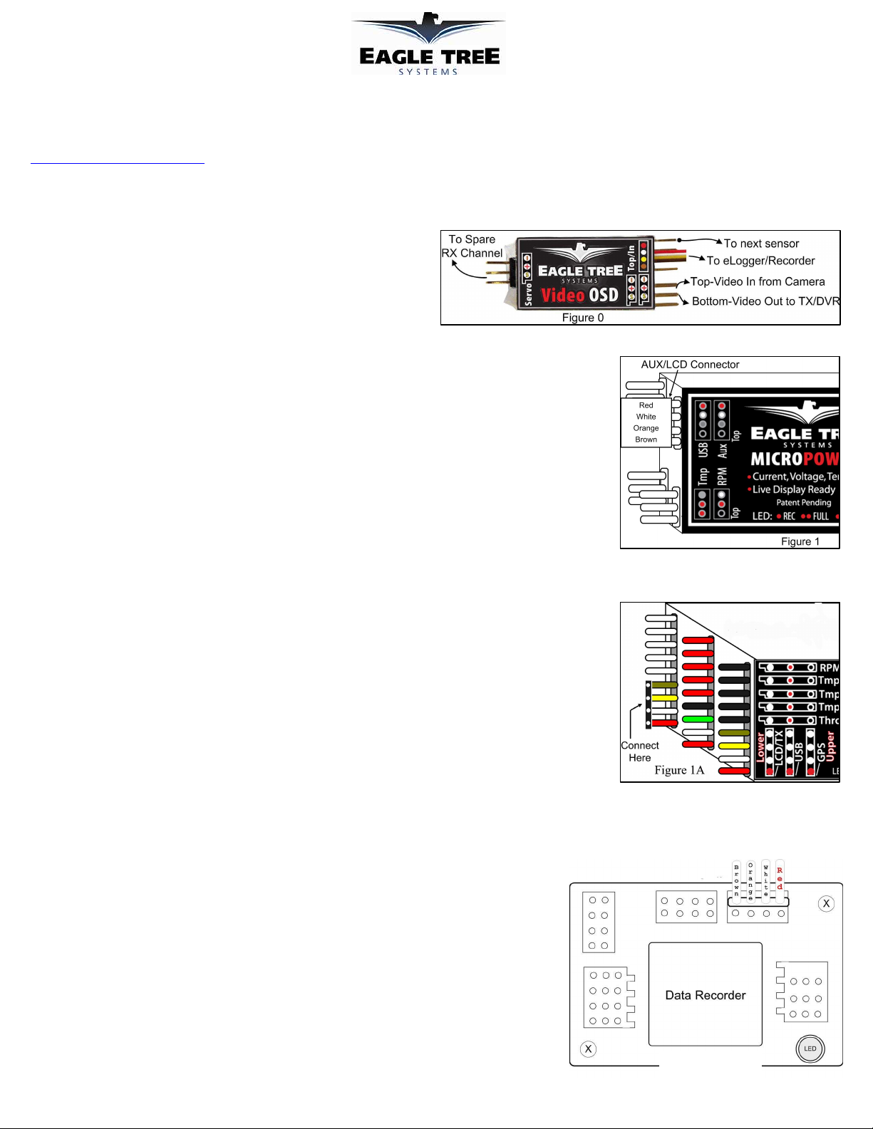
Connecting the Expander to Your Camera and Video Recorder/Transmitter
The two 3 pin connectors on the Expander are used to route the composite video signal into and out of the
Expander. The inputs/outputs work with standard 75 Ohm composite video. The upper connector is video IN,
and the lower connector is video OUT. The “-“ and “signal” pins are the only ones used by the Expander, but
the “+” pins are connected together internally in the Expander, for your convenience.
Connecting the Expander to a Spare Receiver Channel (for remote control of features)
Though not required, the Video Expander can be connected to a spare receiver channel controlled by your radio (such as flaps or landing gear) which will
enable control of the Expander remotely. The features that presently can be controlled by this channel are On/Off and Page Switch (for multiple OSD
pages). Connect the Expander to your spare receiver channel by connecting a “male to male” servo cable between the connector marked “Servo” on the
Expander, and the spare receiver output.
Connecting the Expander to Your Eagle Tree Logger
eLogger V3
The Expander plugs into the “LCD/TX” port of your eLogger V3, as shown in Figure 1A. If you
have a PowerPanel or other Expanders, those can “daisy chain” connect to the pins on the other side
of your Expander, with the polarity as indicated on the Expander label. IMPORTANT: when using
the OSD Expander with the eLogger V3 and the GPS Expander, a maximum voltage of
approximately 16 volts (4s LiPo pack) should be used to power the eLogger. If you are using a pack
greater than 16 volts, the eLogger’s internal regulator may temporarily shut down, which will cause
the OSD Expander to turn off, resulting in no video display. To avoid this issue, use our “Battery
Backup Harness” which can connect to a spare 5V to 6V BEC or spare receiver channel when using
larger battery packs.
Document Version 1.4
Copyright © 2008 Eagle Tree Systems, LLC
http://www.eagletreesystems.com
Figure 1B
Page 2
Page
2
eLogger V1/V2
The Expander plugs into the “Aux” or “LCD” port of your MicroPower eLogger V1/V2, as shown in Figure 1. If you have a PowerPanel or other
Expanders, those can “daisy chain” connect to the pins on the other side of your Expander, with the polarity as indicated on the Expander label.
Data Recorder
The 4 wire connector attached to the Expander plugs into the “FCC TX” port of your Data Recorder as shown in Figure 1B. Make sure that you connect it
in the correct location on the recorder, and with the correct polarity! IMPORTANT: if you do not plan on connecting a Seagull transmitter to the 4
pin “to next sensor” connection of the OSD Expander, make sure you cover the exposed 4 pin connector with tape, or otherwise keep it from
shorting to other metal objects. Touching the exposed 4 pin connector to other metal objects will damage the recorder when it is powered!
Windows Application and Firmware Update
To use the Expander, you must update to Eagle Tree
Windows Application version 6.82 or higher. To update,
download the latest application from the support page of our
website, located at
http://eagletreesystems.com/Support/apps.htm . After
connecting the OSD Expander to the eLogger/Recorder, and
downloading and installing the latest Windows Application,
the firmware of both your eLogger/Recorder and the OSD
Expander will need to be updated. To upgrade your
firmware, just click “Hardware, Firmware Control” and first
click the “Update” button for the eLogger/Recorder, and
repeat this process to update the firmware for the OSD
Expander.
Configuring the Expander with the Windows
Application
After updating the Windows application, and the appropriate
firmware, click “Hardware, Choose Parameters to Display on
Video OSD” to configure the Expander.
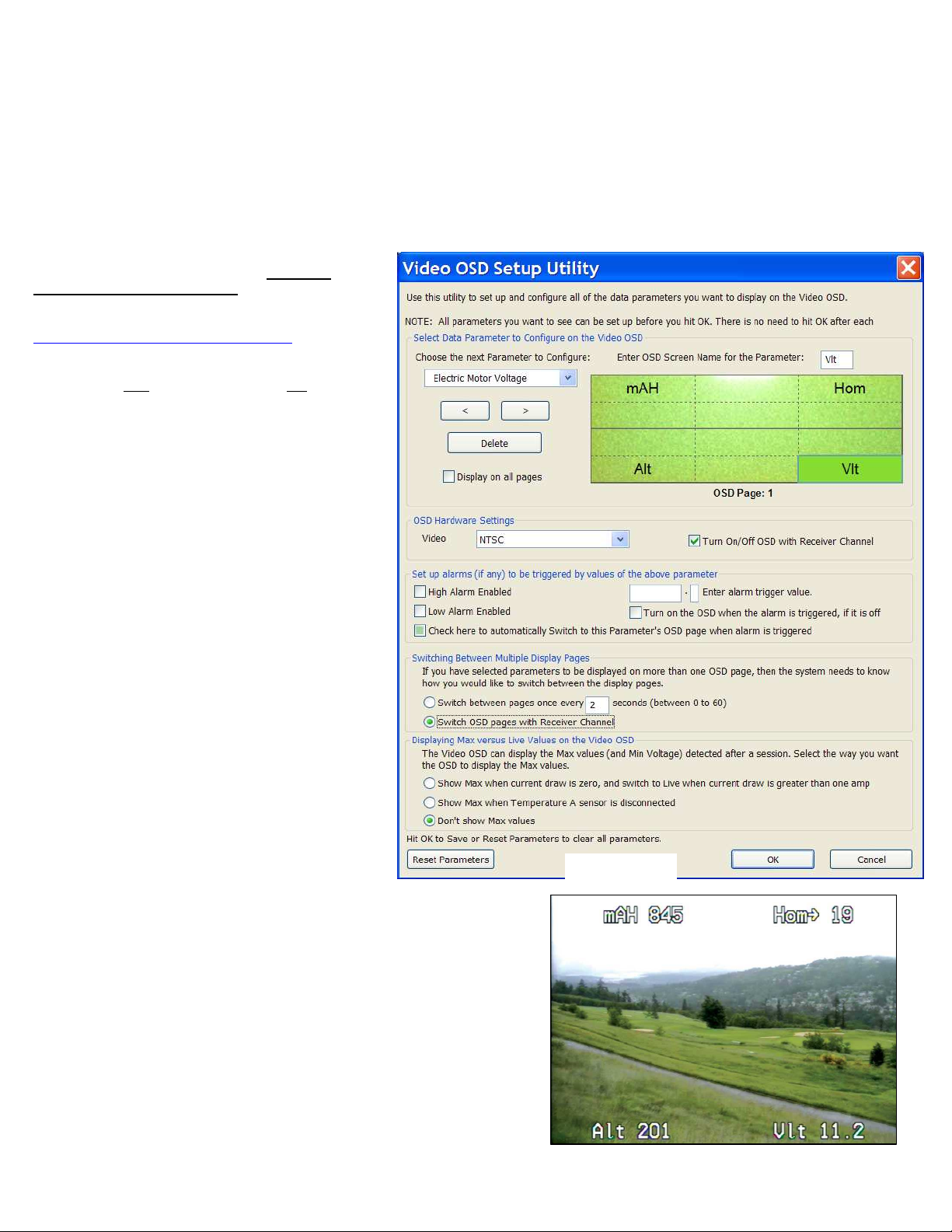
If the hardware is connected correctly, the page shown in
Figure 2 should appear. If it does not appear, please see the
troubleshooting section of this manual. The OSD display
will appear as shown in Figure 3, based on the configuration
selections in Figure 2.
Video Mode
The Video mode (NTSC, PAL or SECAM) is normally
selected for you automatically, based on your country. If you
need to change it, just click the “Video” dropdown and select
the correct mode.
OSD Pages
Multiple “pages” of data can be displayed on the OSD. Each
page can have up to 12 parameters. The simulated display
shown in Figure 2 shows 4 parameters configured to be
displayed on Page 1 of the OSD. To select a different OSD
page for configuration, click the left or right arrow buttons on
the display. The current page number is shown under the simulated display.
Choosing Parameters for Display
To configure a parameter to display, click “Choose the next Parameter to Configure.”
This dropdown menu lets you choose a parameter to display on the OSD screen. The
available parameters depend on your eLogger or Recorder type, and the sensors you have
purchased.
To change the location on the page for displaying the parameter, just click the location
with your mouse, and drag the parameter to the desired location.
To change the name of the parameter on the OSD screen, click on the parameter on the
simulated display, and edit the name with “Enter OSD Screen Name for Parameter.”
If there is a parameter that you would like to display on ALL your pages, click on the
parameter on the simulated display, and click the “Display on all pages” button.
Figure 2
Copyright © 2008 Eagle Tree Systems, LLC
http://www.eagletreesystems.com
Figure 3
Page 3

Page
3
Turning the OSD Off and On with a Spare Receiver Channel
If you want to switch the OSD off and on during operation, select the option “Turn OSD Off/On with Receiver Channel.” Then, during
operation, when the spare receiver channel is switched OFF, the OSD will turn off, and vice versa.
Setting Alarms for Parameters
High or Low alarm triggers can be set on most parameters, which will cause the alarm parameter to flash on the display. Also, if you use a spare receiver
channel to turn the Expander off, you can configure the alarm to turn the Expander back on when a trigger occurs. Also, the alarm can be configured to
switch the Expander to that parameter’s OSD page automatically.
For example, if you want to configure a low voltage alarm of 10 volts, and want the OSD to remain turned OFF until that low voltage is detected, you would
do the following:
1) Add the “Voltage” parameter to the display.
2) With the Voltage parameter highlighted on the simulated display, click “Low Alarm Enabled” and enter “10.0” for the alarm trigger value.
3) Click the “Turn on the OSD when alarm is triggered.” Option.
4) Click the “Check here to automatically Switch to this Parameter’s OSD page when alarm is triggered” option.
Then, while you are operating your vehicle, the OSD can be turned off with your radio, and will turn itself back on, and flash the voltage, when the voltage
goes below 10V.
Switching Between Multiple Display Pages
If more than one OSD display page has been configured, there are two ways of switching between the pages during operation. The first way is to set a page
switch timer, which causes the page to automatically be switched in the specified number of seconds – choose “Switch between pages every ___ seconds”
for this option. The second way is to use the connection to the spare receiver channel to switch the pages – choose “Switch OSD pages with Receiver
Channel” for this option. If this option is chosen, toggling the spare receiver channel OFF and then ON (within 1 second) causes the OSD to advance to the
next page.
Displaying Max vs Live Values
Sometimes it is desirable to have the OSD display the max values (or minimum Voltage) after operation. To do this, choose one of the Max
Values options. The two choices are “Show max values when current draw is zero” which causes max values to be displayed when there is
no current draw through the current sensor (requires a current sensor or the eLogger). The other choice is “Show Max Values when
Temperature A Sensor is Disconnected.” This causes the Max values to be displayed when the first Temperature sensor is disconnected
from the eLogger or Recorder. NOTE: Max values are indicated on the display with a “↑”, or a “↓” for Voltage.
GPS, HOME ARROW and Distance to Pilot Parameter Information
When equipped with our GPS Expander, the OSD can display several GPS related parameters.
If the OSD Expander detects that a GPS is connected, it will not complete initialization until a valid 3D fix is attained. If for some reason you want to skip
the wait for a valid 3D fix, just switch the spare receiver channel off and on quickly. If you are not using the spare receiver channel to switch the OSD,
you will need to disconnect the GPS from the eLogger or Recorder to bypass this check.
The Home Arrow is an arrow and reading indicating the direction to turn to reach “home” (the location where the GPS first acquired a fix after power-up).
To use the Home Arrow, just select the “Home Arrow” parameter for display.
IMPORTANT: The Home Arrow and other OSD information is intended as a safety feature only, and is not intended to be a navigation system for
your model. You should always use a spotter if your eyes are not on your model. Any use of the OSD to attempt to navigate your model is not
supported, and is done at your own risk.
The Home Arrow makes it easy to determine the direction and amount of turn needed to be back on course to home. If the angular distance between the
direction the vehicle is traveling and Home is less than +/- 15 degrees, a forward arrow “↑” is displayed indicating you are approximately on course,
followed by an arrow that indicates the direction to turn “←” or “→”, followed by the angle to turn. For example, if you needed to turn 10 degrees to the
right to be headed perfectly toward home, the following would be displayed: Hom↑→10.
Similarly, if the turn needed is greater than +/-15 degrees, the display shows the amount to turn. For example, if a 45 degree turn to the left is needed to
head for home, the display would be Hom←45. If you are heading almost the opposite direction from home (+/-15 degrees from opposite), the display will
show a “↓” in addition to the turn direction. For example, if you were traveling so that a 170 degree turn to the right was needed to return to home, the
following would be displayed: Hom↓→170.
The Distance to Pilot parameter indicates, in either Feet or Meters, the distance between the model and the location the first GPS fix was acquired.
Configuring Units of Measure
The units of measure are chosen by clicking “Software, Choose Units of Measure.”
Copyright © 2008 Eagle Tree Systems, LLC
http://www.eagletreesystems.com
Page 4

Page
4
Troubleshooting
Below is a list of problems that may be encountered, and steps to remedy them. If your particular issue is not addressed by the below, see the Support page
on http://eagletreesystems.com or email support@eagletreesystems.com. Include a full description of your problem, your machine configuration,
brands/models of receivers, transmitters and servos, Windows Application and Recorder firmware version if possible, and any other relevant details.
Issue: The message “OSD Board is not connected” appears when I try to configure the Expander with the Windows Application.
Solutions:
• Ensure that the Expander is connected correctly, with the correct polarity, to the eLogger or Recorder
• Ensure that the eLogger or Recorder is connected correctly to USB. The LED should flash a sequence of three repeating blinks if it is correctly
connected.
• Ensure that you have updated the recorder firmware and OSD Expander firmware as described in the “Windows Application and Firmware Update”
section above.
Issue: I see only a “black screen” or no image on my DVR or Video Receiver after connecting the OSD Expander between the camera and the Video
Transmitter/DVR.
Solutions:
• Verify that a correct video image is displayed if I remove the OSD Expander and connect the camera and Transmitter/DVR together directly.
• Ensure that the Expander is connected correctly to the eLogger/Recorder, and that the LED on the eLogger/Recorder is flashing. If the LED is not
flashing, that means that the eLogger/Recorder is not powered. No video will appear in this case.
• Ensure that the upper 3 pin connector of the Expander is connected to the output from your camera, with the “S” pin connected to the positive output of
the camera (the center pin for RCA), and the “-“ pin of the Expander going to the negative output (ground) of the camera (the outer connector for
RCA).
• Ensure that the lower 3 pin connector of the Expander is connected to the input of your Video Transmitter or DVR, with the “S” pin connected to the
positive input (the center pin for RCA), and the “-“ pin of the Expander going to the negative input (ground - the outer connector for RCA).
Issue: The OSD Text is visible, but flickers or is distorted.
Solution:
• Verify that the Video Mode selected with the software matches the video output of the camera. Normally, NTSC is used in the USA, and PAL is used
in Europe.
Issue: The OSD Text is visible when my camera is turned on, but only a black screen appears when the camera is turned off.
Solution:
• This is correct behavior. The OSD will not overlay text if there is no active video source.
Issue: I am using the eLogger, and the Video and OSD Text is visible for a while, but then the Video goes blank. If I disconnect the eLogger for a few
minutes and reconnect it, the Video re-appears.
Solution: The Battery Backup Harness will be needed for your configuration. See the “eLogger V3” installation section above for more information.
Issue: I see the message “OSD Powering Down” when I connect the system to power
Solution:
• If you are using a spare receiver channel to turn the OSD on and off, make sure that the radio switch corresponding to that receiver channel is set to the
ON/Open position. If you are using servo reversing on that channel, make sure the radio switch for that channel is in the OFF/Closed position.
•
If you did NOT intend to use a spare receiver channel to turn the OSD on and off, UNCHECK the box as described above in “Turning the OSD Off and
On with a Spare Receiver Channel”and try again.
Specifications
• Video Modes: NTSC, PAL, SECAM
• Parameters Displayed: Limited only by the sensors you have purchased
• On/Off Control: Spare Receiver channel controlled by your Radio
• Character Display Type: High contrast white with black character outline, for optimum visibility.
• Number of Parameters per OSD Page: 12 maximum (2 lines on top, and 2 lines on bottom, with 3 parameters on each line).
Limited Warranty
Eagle Tree Systems, LLC, warrants the Expander to be free from defects in materials and workmanship for a period of one (1) year from the date of original
purchase. This warranty is nontransferable. If your unit requires warranty service during this period, we will replace or repair it at our option. Shipping
cost to us is your responsibility. To obtain warranty service, email support@eagletreesystems.com for further instructions.
This limited warranty does not cover:
• The Software. See the Software license agreement for more information on Software restrictions.
• Problems that result from:
o External causes such as accident, abuse, misuse, or problems with electrical power
o Servicing not authorized by us
o Usage that is not in accordance with product instructions
o Failure to follow the product instructions
THIS WARRANTY GIVES YOU SPECIFIC LEGAL RIGHTS, AND YOU MAY ALSO HAVE OTHER RIGHTS WHICH VARY FROM STATE TO
STATE (OR JURISDICTION TO JURISDICTION). OUR RESPONSIBILITY FOR MALFUNCITONS AND DEFECTS IN HARDWARE IS LIMITED
Copyright © 2008 Eagle Tree Systems, LLC
http://www.eagletreesystems.com
Page 5

Page
5
TO REPAIR AND REPLACEMENT AS SET FORTH IN THIS WARRANTY STATEMENT. ALL EXPRESS AND IMPLIED WARRANTIES FOR
THE PRODUCT, INCLUDING, BUT NOT LIMITED TO, ANY IMPLIED WARRANTIES AND CONDITIONS OF MERCHANTABILITY AND
FITNESS FOR A PARTICULAR PURPOSE, ARE LIMITED IN TIME TO THE TERM OF THE LIMITED WARRANTY PERIOD AS DESCRIBED
ABOVE. NO WARRANTIES, WHETHER EXPRESS OR IMPLIED, WILL APPLY AFTER THE LIMITED WARRANTY PERIOD HAS EXPIRED.
SOME STATES DO NOT ALLOW LIMITATIONS ON HOW LONG AN IMPLIED WARRANTY LASTS, SO THIS LIMITATION MAY NOT APPLY
TO YOU.
WE DO NOT ACCEPT LIABILITY BEYOND THE REMEDIES PROVIDED FOR IN THIS LIMITED WARRANTY OR FOR CONSEQUENTIAL OR
INCIDENTAL DAMAGES, INCLUDING, WITHOUT LIMITATION, ANY LIABILTY FOR THIRD-PARTY CLAIMS AGAINST YOU FOR
DAMAGES, FOR PRODUCTS NOT BEING AVAILABLE FOR USE, OR FOR LOST DATA OR LOST SOFTWARE. OUR LIABILITY WILL BE NO
MORE THAN THE AMOUNT YOU PAID FOR THE PRODUCT THAT IS THE SUBJECT OF A CLAIM. THIS IS THE MAXIMUM AMOUNT FOR
WHICH WE ARE RESPONSIBLE. SOME STATES DO NOT ALLOW THE EXCLUSION OR LIMITATION OF INCIDENTAL OR
CONSEQUENTIAL DAMAGES, SO THE ABOVE LIMITATION OR EXCLUSION MAY NOT APPLY TO YOU.
Copyright © 2008 Eagle Tree Systems, LLC
http://www.eagletreesystems.com
 Loading...