

Page 1

FlightDEK-D180
Installation Guide
This product is not approved for installation in type certificated aircraft
P/N 100600-000, Revision H
For use with firmware version 5.4
August, 2010
Copyright © 2003-2010 by Dynon Avionics, Inc.
Page 2

Page 3

Contact Information
Dynon Avionics, Inc.
19825 141
st
Place NE
Woodinville, WA 98072
Phone: (425) 402-0433 - 7:00 AM – 5:00 PM (Pacific Time) Monday - Friday
Fax: (425) 984-1751
Dynon Avionics offers online sales, extensive support, and continually-updated information on its products via its
Internet sites:
www.dynonavionics.com/support
docs.dynonavionics.com
– Current and archival documentation.
downloads.dynonavionics.com
support.dynonavionics.com
store.dynonavionics.com
wiki.dynonavionics.com
– Dynon’s secure online store for purchasing all Dynon products 24 hours a day.
– Dynon Avionics’ Documentation Wiki provides enhanced, extended,
–Dynon Avionics primary web site; including:
– Software downloads.
– Support resources.
continuously-updated online documentation contributed by Dynon employees and customers.
forum.dynonavionics.com
– Dynon Avionics’ Internet forum where Dynon customers can interact and
receive Dynon technical support outside of telephone support hours. A key feature of the forum is that it
allows the exchange of diagrams, photos, and other types of files.
newsletter.dynonavionics.com
blog.dynonavionics.com
– Dynon’s email newsletter.
– Dynon’s blog where you can find new and interesting Dynon-related content.
Copyright
2003-2010 Dynon Avionics, Inc. All rights reserved. No part of this manual may be reproduced, copied, transmitted, disseminated or stored in
any storage medium, for any purpose without the express written permission of Dynon Avionics. Dynon Avionics hereby grants permission to
download a single copy of this manual and of any revision to this manual onto a hard drive or other electronic storage medium to be viewed for
personal use, provided that such electronic or printed copy of this manual or revision must contain the complete text of this copyright notice and
provided further that any unauthorized commercial distribution of this manual or any revision hereto is strictly prohibited.
Information in this document is subject to change without notice. Dynon Avionics reserves the right to change or improve its products and to
make changes in the content without obligation to notify any person or organization of such changes. Visit the Dynon Avionics website
(www.dynonavionics.com
products.
) for current updates and supplemental information concerning the use and operation of this and other Dynon Avionics
Limited Warranty
Dynon Avionics warrants this product to be free from defects in materials and workmanship for three years from date of shipment. Dynon
Avionics will, at its sole option, repair or replace any components that fail in normal use. Such repairs or replacement will be made at no charge
to the customer for parts or labor. The customer is, however, responsible for any transportation cost. This warranty does not cover failures due to
abuse, misuse, accident, improper installation or unauthorized alteration or repairs.
THE WARRANTIES AND REMEDIES CONTAINED HEREIN ARE EXCLUSIVE, AND IN LIEU OF ALL OTHER WARRANTIES
EXPRES
SED OR IMPLIED, INCLUDING ANY LIABILITY ARISING UNDER WARRANTY OF MERCHANTABILITY OR FITNESS
FOR A PARTICULAR PURPOSE, STATUTORY OR OTHERWISE. THIS WARRANTY GIVES YOU SPECIFIC LEGAL RIGHTS, WHICH
MAY VARY FROM STATE TO STATE.
IN NO EVENT SHALL DYNON AVIONICS BE LIABLE FOR ANY INCIDENTAL, SPECIAL, INDIRECT OR CONSEQUENTIAL
DAMA
GES, WHETHER RESULTING FROM THE USE, MISUSE OR INABILITY TO USE THIS PRODUCT OR FROM DEFECTS IN
THE PRODUCT. SOME STATES DO NOT ALLOW THE EXCLUSION OF INCIDENTAL OR CONSEQUENTIAL DAMAGES, SO THE
ABOVE LIMITATIONS MAY NOT APPLY TO YOU.
Dynon Avionics retains the exclusive right to repair or replace the instrument or firmware or offer a full refund of the purchase price at its sole
discretion. SUCH REMEDY SHALL BE YOUR SOLE AND EXCLUSIVE REMEDY FOR ANY BREACH OF WARRANTY.
T
hese instruments are not intended for use in type certificated aircraft at this time. Dynon Avionics makes no claim as to the suitability of its
products in connection with FAR 91.205.
Dynon Avionics’ products incorporate a variety of precise, calibrated electronics. Except for replacing the optional internal backup battery in
EFIS-based products per the installation guide, our products do not contain any field/user-serviceable parts. Units that have been found to have
been taken apart may not be eligible for repair under warranty. Additionally, once a Dynon Avionics unit is opened up, it will require calibration
and verification at our Woodinville, WA offices before it can be considered airworthy.
Page 4

Page 5

Table of Contents
Contact Information......................................................................................................................................................iii
Copyright......................................................................................................................................................................iii
Limited Warranty .........................................................................................................................................................iii
1. 1-1 Introduction
OEM Installations...................................................................................................................................................... 1-1
Warning ..................................................................................................................................................................... 1-1
About this Guide........................................................................................................................................................ 1-2
Menu Descriptions..................................................................................................................................................... 1-2
2. 2-1 Wiring Overview
Recommended Wiring Practices................................................................................................................................2-1
Power Requirements.................................................................................................................................................. 2-1
Grounding.................................................................................................................................................................. 2-2
+5V Excitation........................................................................................................................................................... 2-3
Thermocouple Harness Preparation........................................................................................................................... 2-3
Harness Mating.......................................................................................................................................................... 2-3
25-Pin Female EFIS Harness..................................................................................................................................... 2-4
37-Pin Female EMS Harness..................................................................................................................................... 2-7
25-Pin Male EMS Harness ........................................................................................................................................ 2-9
3. 3-1 Transducer Installation
Tools and Equipment Required ................................................................................................................................. 3-1
Exhaust Gas Temperature (EGT) Probes................................................................................................................... 3-2
Cylinder Head Temperature (CHT) Probes ............................................................................................................... 3-3
Tachometer................................................................................................................................................................ 3-4
Manifold Pressure Sensor.......................................................................................................................................... 3-5
Oil Pressure Sensor.................................................................................................................................................... 3-6
Oil Temperature Sensor............................................................................................................................................. 3-7
Fuel Pressure Sensor.................................................................................................................................................. 3-7
Fuel Flow Sensor....................................................................................................................................................... 3-9
Fuel Level Sensor .....................................................................................................................................................3-11
Ammeter Shunt.........................................................................................................................................................3-12
General Purpose Inputs.............................................................................................................................................3-13
Contacts ....................................................................................................................................................................3-18
General Purpose Thermocouple ...............................................................................................................................3-19
4. 4-1 Instrument Installation
Selecting a Remote Compass Module Location ........................................................................................................ 4-1
EDC-D10A Communication Cable ........................................................................................................................... 4-2
Power Inputs.............................................................................................................................................................. 4-3
Serial Communication Cables ................................................................................................................................... 4-4
SL30 and/or GPS connection..................................................................................................................................... 4-6
Altitude Encoder Wiring ........................................................................................................................................... 4-8
External EMS Warning Light...................................................................................................................................4-10
Audio Alert Outputs .................................................................................................................................................4-10
Dynon Smart Avionics Bus (DSAB) Wiring............................................................................................................4-11
Panel Location and Mounting...................................................................................................................................4-13
Connecting Static & Pitot Lines ...............................................................................................................................4-14
5. 5-1 EFIS Calibration and Configuration
Ensuring Proper Installation ...................................................................................................................................... 5-1
Setting Zero Pitch (In flight)...................................................................................................................................... 5-1
FlightDEK-D180 Installation Guide v
Page 6

Table of Contents
Compass Heading Calibration ................................................................................................................................... 5-1
Configure Airspeed Color Thresholds....................................................................................................................... 5-4
6. 6-1 EMS Configuration
Full-Page Setup Menu Overview............................................................................................................................... 6-1
Alarm and Color Threshold Configuration................................................................................................................ 6-2
Global Parameters Setup ........................................................................................................................................... 6-3
Engine Type Configuration ....................................................................................................................................... 6-4
Fuel Level Calibration ............................................................................................................................................... 6-5
Trim Calibration ........................................................................................................................................................ 6-6
Flaps Calibration ....................................................................................................................................................... 6-7
Tachometer................................................................................................................................................................ 6-8
Manifold Pressure...................................................................................................................................................... 6-8
Oil Pressure ............................................................................................................................................................... 6-9
Oil Temperature......................................................................................................................................................... 6-9
Exhaust Gas Temperature (EGT) .............................................................................................................................6-10
Cylinder Head Temperature (CHT)..........................................................................................................................6-11
Fuel Level.................................................................................................................................................................6-13
Fuel Pressure ............................................................................................................................................................6-13
Fuel Flow..................................................................................................................................................................6-14
Voltage .....................................................................................................................................................................6-15
Current......................................................................................................................................................................6-15
General Purpose Inputs.............................................................................................................................................6-16
Contacts ....................................................................................................................................................................6-18
General Purpose Thermocouple ...............................................................................................................................6-19
7. 7-1 DSAB Configuration
Network Concepts ..................................................................................................................................................... 7-1
Example Networks .................................................................................................................................................... 7-2
Initial Setup ............................................................................................................................................................... 7-4
Brightness Configuration........................................................................................................................................... 7-5
Network Status .......................................................................................................................................................... 7-6
8. 8-1 Autopilot Installation and Configuration
Additional Information and Updates ......................................................................................................................... 8-1
DSAB Firmware Compatibility................................................................................................................................. 8-2
Compass Calibration Critical For Certain AP Modes................................................................................................ 8-2
Autopilot System Electrical Installation .................................................................................................................... 8-3
Servo Mechanical Installation ................................................................................................................................... 8-6
AP74 Mechanical Installation...................................................................................................................................8-11
Firmware Upgrades Required For AP Functionality ................................................................................................8-13
AP Servo Configuration ...........................................................................................................................................8-14
AP74 Configuration..................................................................................................................................................8-30
9. 9-1 Appendix
Appendix A: Ongoing Maintenance and Troubleshooting........................................................................................ 9-1
Appendix B: Dynon EFIS OAT Probe Installation and Usage.................................................................................. 9-7
Appendix C: HS34 Installation and Configuration...................................................................................................9-10
Appendix D: Dynon AOA/Pitot Installation and Calibration ...................................................................................9-24
Appendix E: Encoder Serial-to-Gray Code Converter Installation...........................................................................9-32
Appendix F: Capacitance-to-Voltage Converter Installation....................................................................................9-35
Appendix G: Replacing the FlightDEK-D180 battery pack .....................................................................................9-36
Appendix H: Weights...............................................................................................................................................9-36
Appendix I: FlightDEK-D180 Specifications...........................................................................................................9-38
vi FlightDEK-D180 Installation Guide
Page 7

1. INTRODUCTION
This manual provides information about the physical, electrical, and plumbing installation of the
FlightDEK-D180, EDC-D10A, optional AOA pitot probe, and all engine sensors purchased from
Dynon Avionics. Additionally, this guide deals with setting up the installation-dependant
firmware options. Because you may not have purchased all the components, you need only read
through the relevant sections of this guide. Information about the operation of this instrument
can be found in the FlightDEK-D180 Pilot’s User Guide.
The EFIS component of the FlightDEK-D180 uses solid-state sensor technology to give an
accurate and easy-to-understand display. To ensure accuracy in its readings, it is very important
that you install the instrument correctly and perform the specified calibration steps. This
installation guide helps you through that process.
OEM Installations
If your FlightDEK-D180 is installed by an OEM distributor, you may find that you are unable to
access some menus and settings. Some Dynon distributors customize various areas of the
FlightDEK-D180 firmware to maintain a consistent pilot experience and minimize integration
issues across a large number of installations. Currently, OEMs can customize access levels to the
following settings on Dynon systems: EMS GLOBAL setup menu, EMS SENSOR setup menu,
fuel calibration, trim calibration, flaps calibration, GPS/NAV setup menu, screen configurations,
data logging, and checklists/data panels. OEM distributors have the option of customizing some
or all of these areas. Please contact your aircraft’s manufacturer if you have any questions about
how your unit has been customized.
Warning
Dynon Avionics’ products incorporate a variety of precise, calibrated electronics. Except for
replacing the optional internal backup battery in EFIS-based products per the installation guide,
our products do not contain any field/user-serviceable parts. Units that have been found to have
been taken apart may not be eligible for repair under warranty. Additionally, once a Dynon
Avionics unit is opened up, it will require calibration and verification at our Woodinville, WA
offices before it can be considered airworthy.
FlightDEK-D180 Installation Guide 1-1
Page 8

Introduction
About this Guide
In the electronic (.PDF) version of this manual, page and section references in the Table of
Contents and elsewhere act as hyperlinks taking you to the relevant location in the manual. The
latest version of this manual is available on the Dynon Avionics website at
docs.dynonavionics.com.
The following icons are used in this guide:
Any text following this icon describes functionality available only with the HS34 HSI
Expansion Module connected to your system.
Any text following this icon describes functionality available only with the AP74
Autopilot Interface Module connected to your system.
Any text following this icon describes functionality that is possible when multiple Dynon
Avionics products are networked together via the Dynon Smart Avionics Bus (DSAB).
Any text following this icon refers to a setting or situation which merits particularly close
attention.
Menu Descriptions
Throughout this guide, the “>“ character is used to indicate entering a deeper level of the menu
system. For example, “EFIS > INFO > LEFT” indicates entering the EFIS menu, pressing
MORE, then pressing INFO, and then pressing LEFT to enter the left info item menu. Note that
the MORE button is not shown in the sequence, since pressing MORE reveals more options in
the same level of the menu system.
1-2 FlightDEK-D180 Installation Guide
Page 9

2. WIRING OVERVIEW
Please follow these instructions explicitly as improper wiring can result in permanent damage to
your instrument and/or the accompanying sensors.
All electrical power and EFIS-specific lines interface with the FlightDEK-D180 via the female
25-pin D-sub connector on the back of the instrument. All EMS-related sensor inputs enter the
FlightDEK-D180 via the male 37-pin and female 25-pin D-sub connectors on the back of the
instrument. Ensure that the unit powers on and that all indicators display expected values before
completing the final physical assembly.
Recommended Wiring Practices
For all electrical connections, use correct wiring techniques, taking care to properly
insulate any exposed wire. A short circuit between any of the wires may cause damage to
the FlightDEK-D180 and/or your aircraft. Make all connections to your harness before
plugging it into any of the components of the system. Do not make connections while
power is applied at any point in the system.
Dynon Avionics sells wiring harnesses for all connections to the FlightDEK-D180. The
harnesses are made up of 22 AWG wire and – with the exception of the thermocouple harnesses
– meet Mil Standard MIL-W-22759/16 (Tefzel insulation). If you have opted not to purchase
these harnesses, please refer to the provided wiring diagrams for construction information. We
recommend that all wire you use also meets Mil Standard MIL-W-22759/16; all wire supplied by
Dynon Avionics (with the exception of thermocouple wire, which uses FEP insulation) meets
this specification.
When using any pre-manufactured harness, verify that each pin has continuity with the expected
wire on the wiring diagram. This test can be easily done with a multimeter. When verifying
harnesses, use the wiring charts and diagrams in this guide as your ultimate authority on pin
function (for any harness) and wire color (for harnesses purchased from Dynon Avionics).
Route all wiring through the engine compartment such that there are no spots where it could
chafe or break. Use appropriate strain relief at all junctions between wires and connectors. We
recommend that you secure all wires at regular intervals along wiring runs to accommodate
vibration effects.
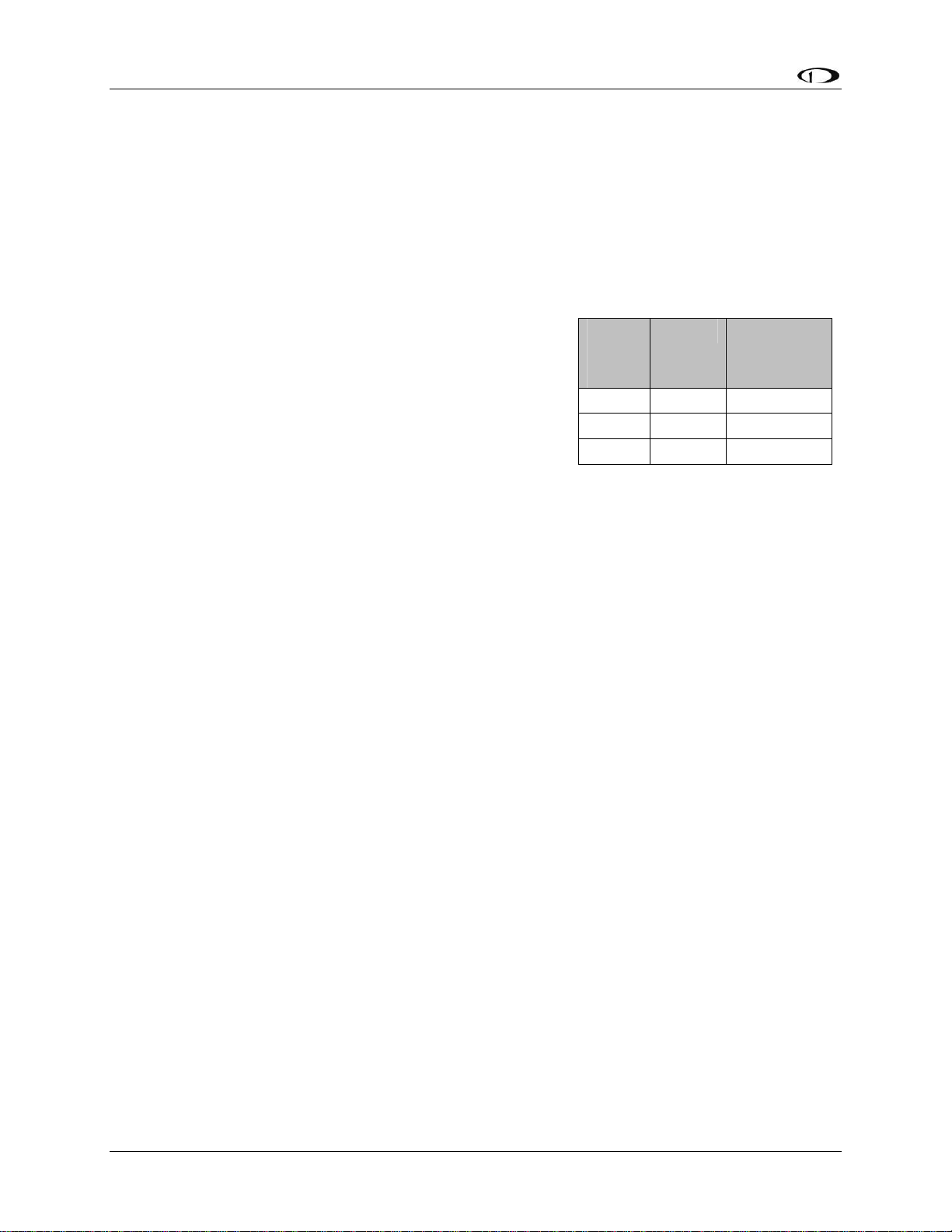
In the sections below, many connections have an
associated legend, as shown at right. All connections on
the EMS male 25-pin harness route to thermocouples and
are color-coded to correspond to the thermocouple
coloring. All connections on the EFIS female 25-pin harness are described in the 25-Pin Female
EFIS Harness section on page 2-4.
Pin Color Function
# Color function
Power Requirements
22 AWG wire is normally sufficient for the power supply and ground lines, but we recommend
that you consult a wire sizing chart and determine the size required for the wire routing in your
particular aircraft. Ensure that the power lines include a circuit breaker or an appropriately sized
FlightDEK-D180 Installation Guide 2-1
Page 10
Wiring Overview
fuse for the wire you select. Power is fed to the FlightDEK-D180 via pins in the female D-25
connector as shown on the 25-Pin Female EFIS Harness diagram on page 2-4.
The FlightDEK-D180 system-wide power requirement is 14 watts typical and 19 watts
maximum. On a 12-volt system, this translates to about 1.5 amps of maximum current draw. On
a 24-volt system, this translates to about 0.8 amps maximum current draw. Normally, a 3-amp
circuit breaker or fuse is sufficient.
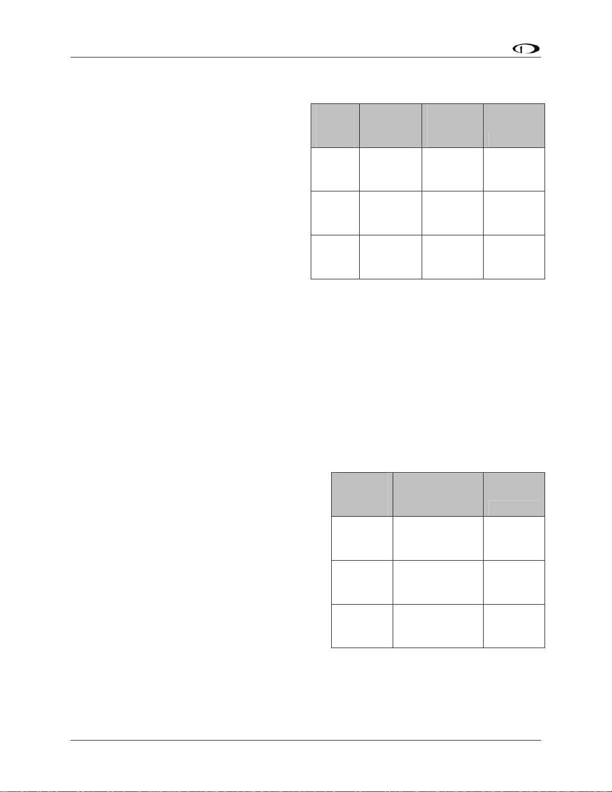
Grounding
Many of the engine sensors require a connection to a
shared electrical ground with the FlightDEK-D180. There
are many places on an aircraft where you could connect
these sensors. However, the ideal location to ground these
sensors is near the FlightDEK-D180 to minimize voltage
differences between the sensor and instrument grounds.
Some sensors (e.g., oil pressure and oil temperature)
connect to ground via their cases’ contact with the engine
or aircraft body. There must be a solid connection between
this “case ground” and the FlightDEK-D180 ground. The oil temperature sensor is very
susceptible to voltage differences between the engine case and the negative terminal of the
battery. Ensure that solid, thick electrical connections exist between the engine and battery
ground. Other sensors (e.g., fuel pressure) do not have a grounded case and have two leads
instead. One lead must be connected to ground, the other to the sensing input of the FlightDEKD180. The FlightDEK-D180 has 3 pins on the 37-pin harness which may be used for connecting
such sensors to ground. More than one sensor’s ground may be connected to any of these three
grounds using a splice.
The case of the FlightDEK-D180 is connected to its supply ground. If your panel is connected to
aircraft ground, the connection between the instrument’s case and the panel dramatically helps
minimize voltage differences between the instrument and sensor grounds. If your panel is not
metal, or is otherwise isolated from engine ground, connect a 14 AWG or larger wire to the
instrument case. The most convenient place to do this is at the back of the mounting tray.
Additionally, connect any unused EMS ground leads to a convenient ground. Keep all ground
leads as short as possible.
EMS
DB37
Pin
5 Black Ground
16 Black Ground
17 Black Ground
Color Function
Because of the current drawn by the FlightDEK-D180, even very small resistances between
battery ground and instrument ground can cause voltage differences which adversely affect
engine sensor readings. An easy way to test the quality of the instrument’s ground is to measure
voltage between the ground pin at the FlightDEK-D180 and the ground lead at your aircraft’s
battery. With the FlightDEK-D180 powered on, connect one lead of your voltmeter to a free
ground lead coming from the FlightDEK-D180. Connect the other lead of your voltmeter to the
ground terminal of your battery. The voltage between these two points should measure very
close to 0 mV (within 5 mV). If it does not, you must improve the ground connection between
the ground of your battery and that of your avionics bus.
2-2 FlightDEK-D180 Installation Guide
Page 11
Wiring Overview
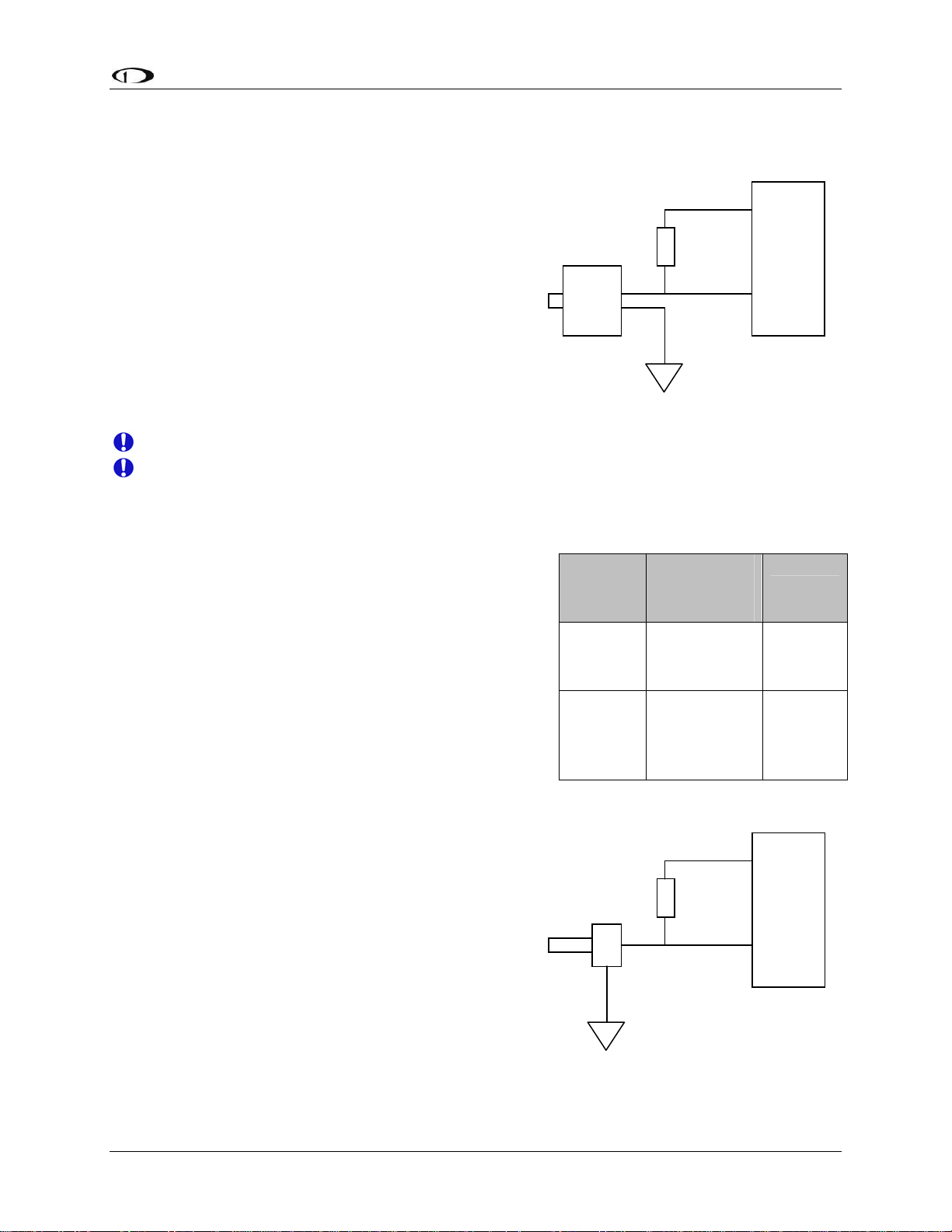
+5V Excitation
Some of the sensors require either a direct connection, or
connection via a resistor, to the +5V excitation circuit. We
recommend that you allow for more than one splice into
this line.
EMS
DB37
Pin
18 White/red
Color Function
+5V
excitation
Thermocouple Harness Preparation
Refer to the 25-Pin Male EMS Harness section on page 2-9 during this procedure. Strip 1” of
brown outer insulation off each thermocouple wire pair on the supplied 25-pin thermocouple
harness. Strip ¼” of insulation from each of the thermocouple wires inside. Crimp the supplied
male Fastons onto each wire on the thermocouple harness. These will later be inserted into the
female Fastons on each thermocouple.
Do not connect the Fastons on the harness with those on the thermocouples until you have routed
the wires and mounted the thermocouples at the desired location.
The thermocouple wires can be cut to a desired length if your application requires. If you need to
extend the length of the thermocouple, you must use the correct type (J or K) thermocouple wire
to accomplish this. It is acceptable to use non-thermocouple fasteners to join two pieces of
thermocouple pair wire, provided the junction does not extend very far or have large temperature
differences across it. Please contact Dynon Avionics to order extension wire.
Harness Mating
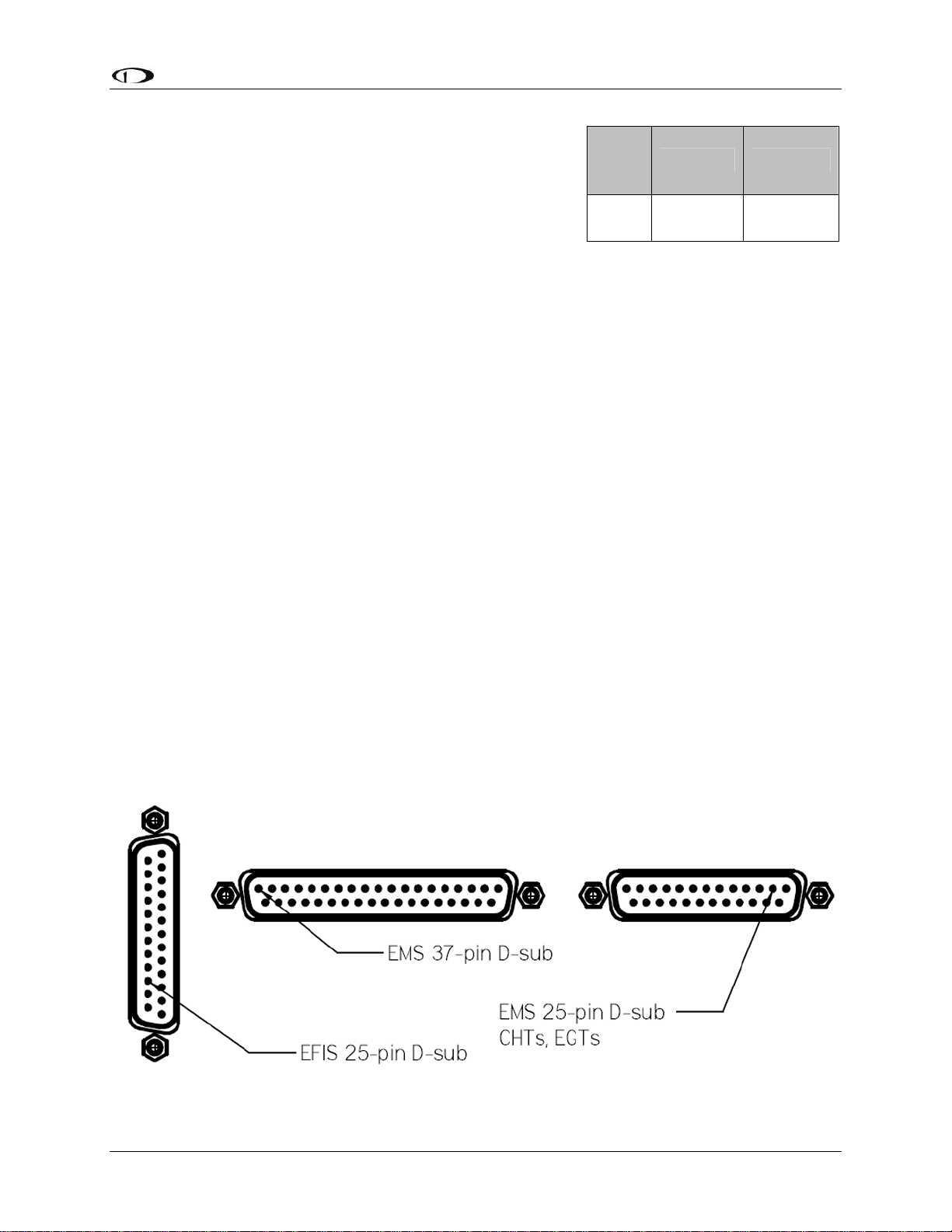
The following diagram shows the 3 electrical connectors on the back of the FlightDEK-D180.
The two horizontal connectors are used for the EMS portion of the product; the vertical
connector is used for the EFIS portion. The main EMS harness (for all connections except EGT
& CHT thermocouples) should terminate in a 37-pin female D-sub connector. The EGT/CHT
thermocouple harness should terminate in a 25-pin male D-sub connector. The EFIS harness
(also used to provide power to the instrument) should terminate in a 25-pin female D-sub
connector. The following pages provide wiring diagrams and details for each of these harnesses.
FlightDEK-D180 Installation Guide 2-3
Page 12
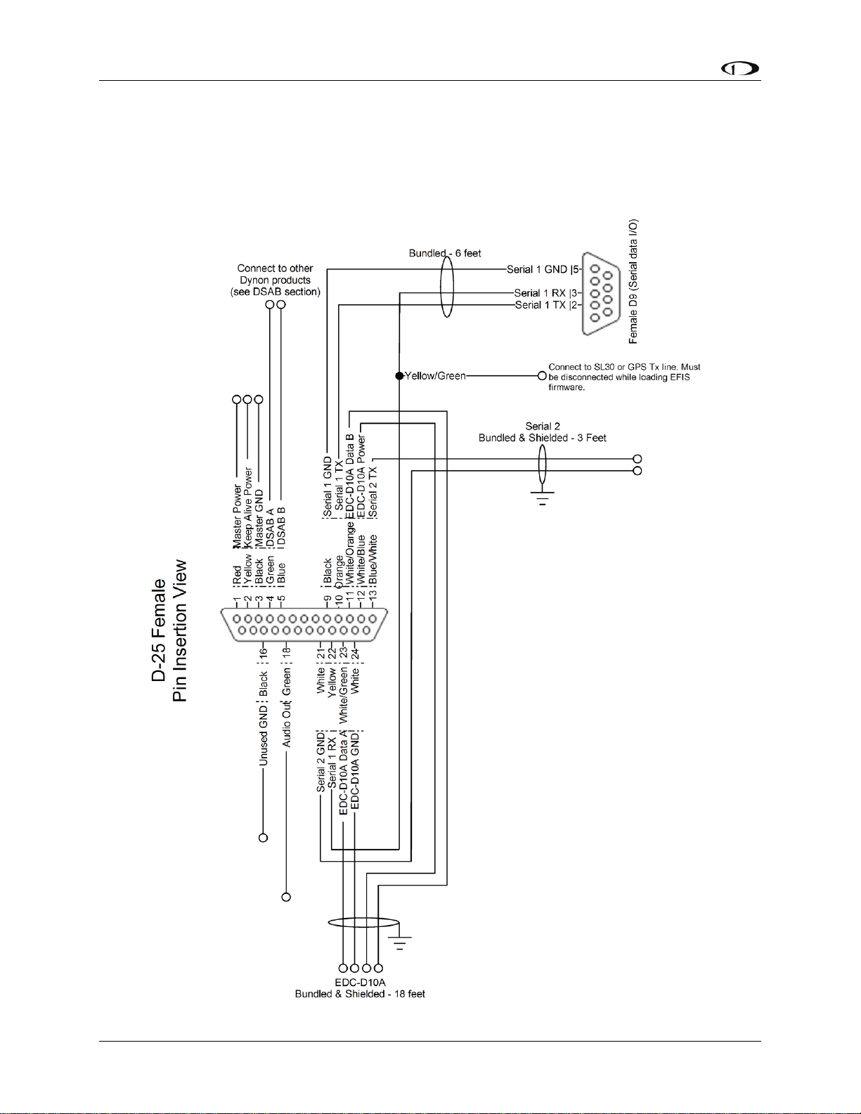
25-Pin Female EFIS Harness
Below is the wiring diagram of the EFIS 25-pin female harness. If you purchased your harness
from Dynon Avionics, it is color coded according to the chart on the following page. Unless
noted otherwise, all wires are 3 feet long on the Dynon-provided harness.
2-4 FlightDEK-D180 Installation Guide
Page 13

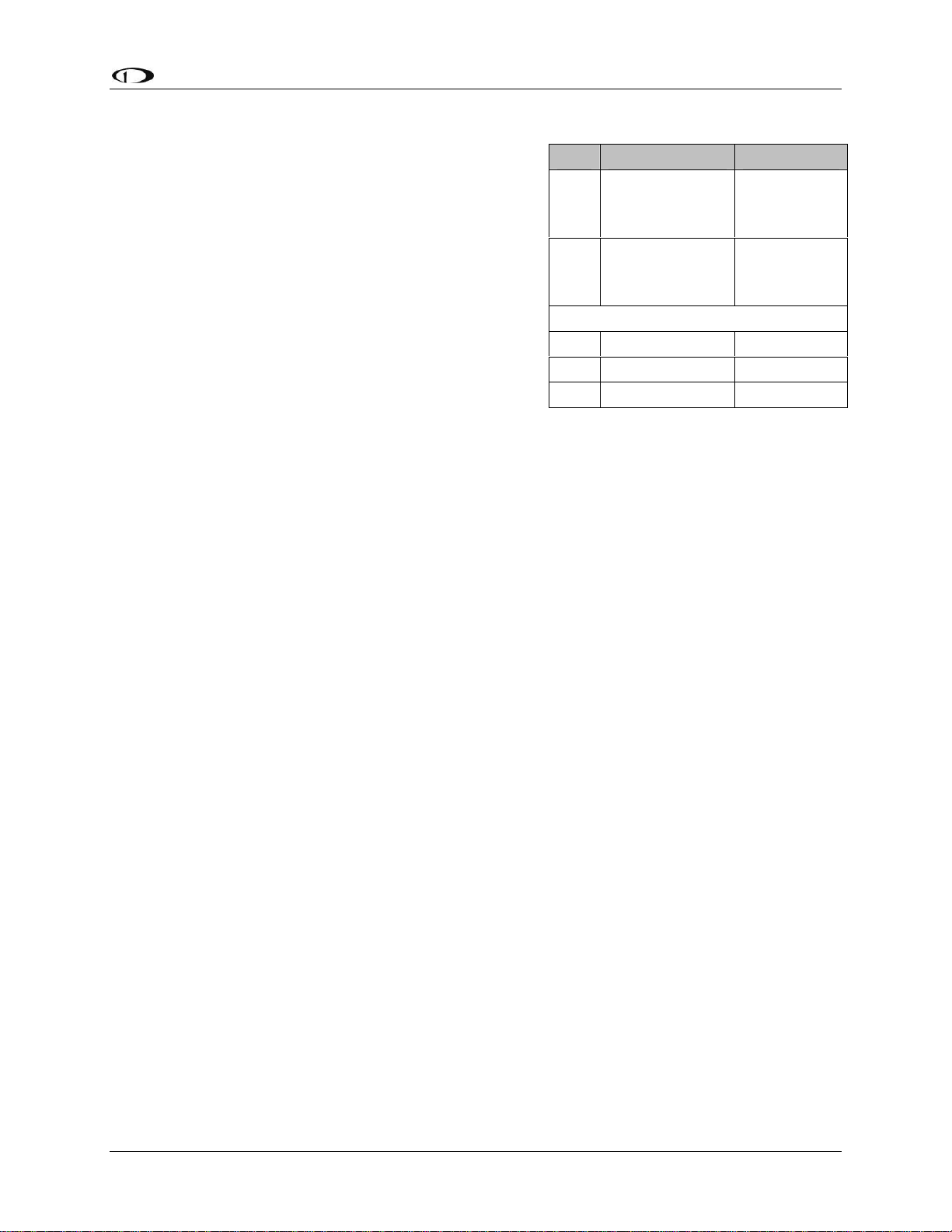
The pin assignments for the female 25-pin harness are repeated below. Note that the pin numbers
are labeled on the face of both the female and male connector. Each connection on the harness
supplied by Dynon is color-coded. These colors are listed in the following chart.
Female
DB25
Pin#
1 Red Master Power (10-30 volts) Page 4-2
2 Yellow Keep Alive Power (10-30 volts, always on) Page 4-2
3 Black Master Ground Page 4-2
4 Green DSAB-A Page 4-11
5 Blue DSAB-B Page 4-11
6 N/A No Connect
7 N/A No Connect
8 N/A No Connect
9 Black (bundled) PC Serial Ground – EFIS logging only Page 4-5
10 Orange (bundled)
11
12
13
14 N/A No Connect
15 N/A External Backup Power Page 4-2
16 Black Ground
17 N/A No Connect
18 Green Audio Alert Out Page 4-10
19 N/A No Connect
20 N/A No Connect
21
22 Yellow (Bundled)
23
24 White EDC-D10A GND Page 4-2
25 N/A No Connect
Dynon Harness
Wire Color
White/Orange (Red
on some harnesses)
White/Blue (Black
on some harnesses)
Blue/White (black
on some harnesses)
White (Bundled in
Encoder cable)
White/Green (Green
on some harnesses)
Function Details
FlightDEK-D180 Transmit / PC Serial
Receive (RS-232) – EFIS logging only
EDC-D10A Data B
EDC-D10A Power (12V)
Serial Encoder Transmit (RS-232)
Serial Encoder Ground
FlightDEK-D180 Receive / PC Serial
Transmit (RS-232) – EFIS logging
EDC-D10A Data A
Page 4-4
Page 4-2
Page 4-2
Page 9-32
Page 9-32
Page 4-5
Page 4-2
FlightDEK-D180 Installation Guide 2-5
Page 14
Wiring Overview
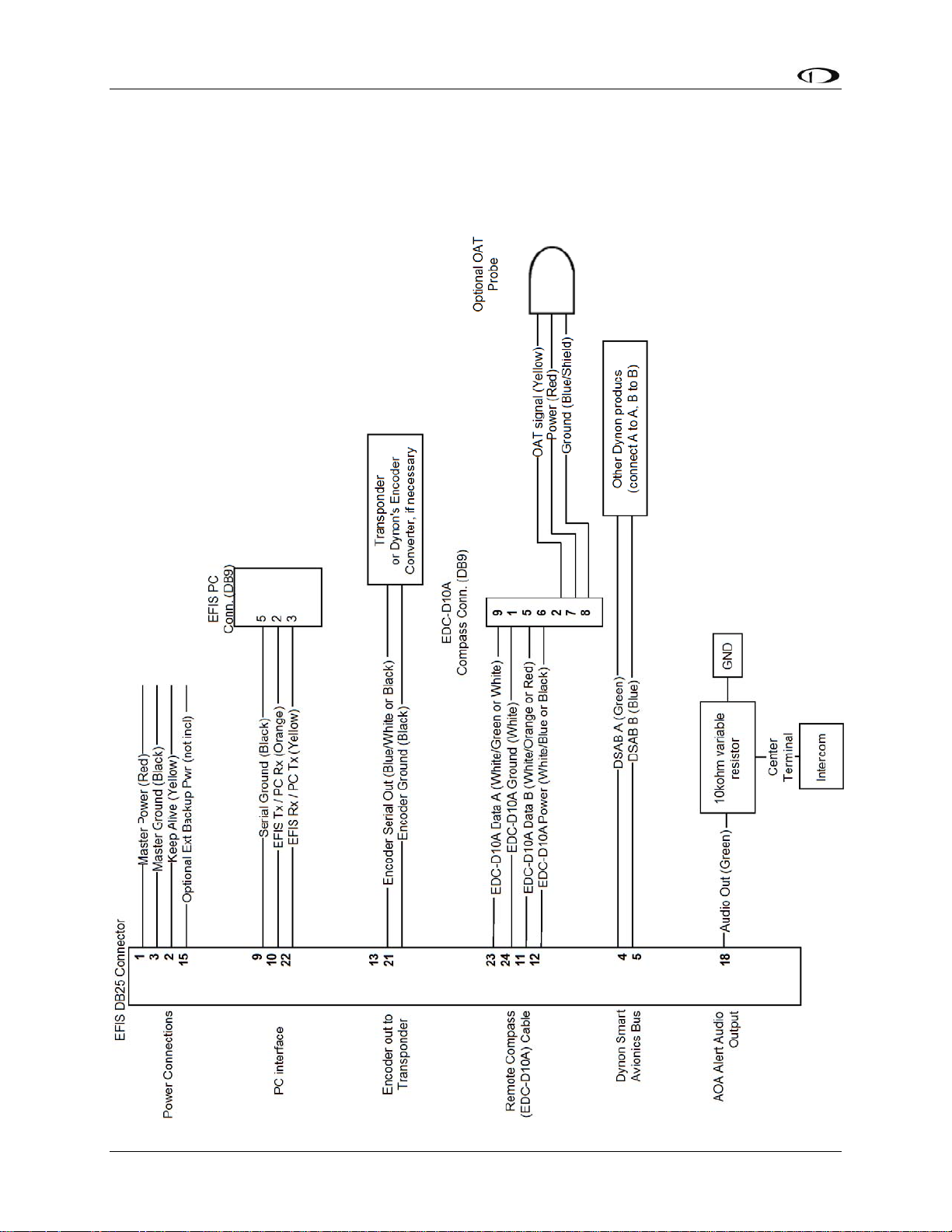
WIRING SYSTEM OVERVIEW
The following block diagram depicts the basic layout of the EFIS DB25 electrical connections
and is for reference only. Read the specific instructions for each connection prior to installation.
The colors shown refer to the Dynon-supplied EFIS harness.
2-6 FlightDEK-D180 Installation Guide
Page 15
Wiring Overview
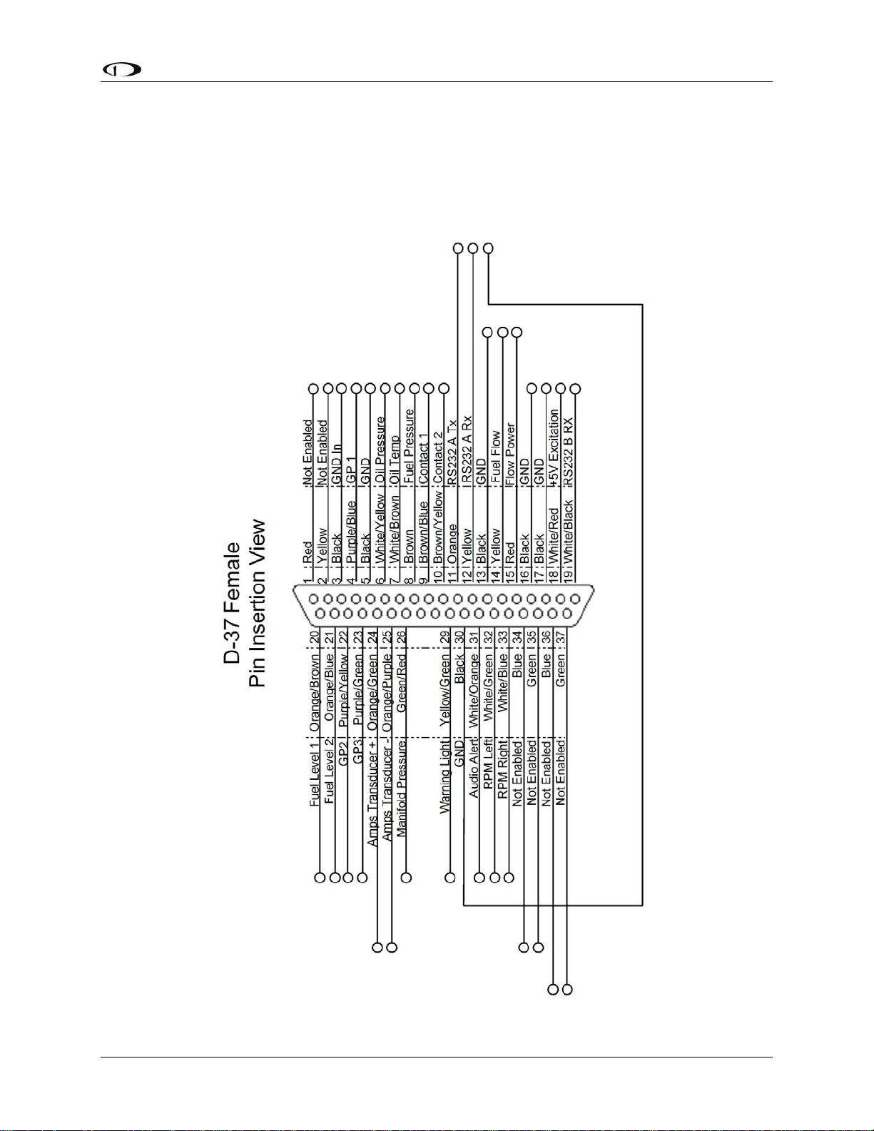
37-Pin Female EMS Harness
Below is the wiring diagram of the EMS 37-pin female harness. If you purchased your harness
from Dynon Avionics, pins 1, 2, 34, 35, 36, and 37 have wires inserted, but are not used. You
may clip the wires or remove the pins as needed. Refer to the following page for detailed pin out
descriptions.
FlightDEK-D180 Installation Guide 2-7
Page 16

Wiring Overview
The pin assignments for the female 37-pin harness are repeated below. Note that the pin numbers
are labeled on the face of both the female and male connector. Each connection on the harness
supplied by Dynon is color-coded. These colors are listed in the following chart.
DB37 harness
Pin#
1 Red
2 Yellow
3 Black Ground Page 2-2
4 Purple/blue GP 1 (general purpose resistive) Page 3-13
5 Black Ground Page 2-2
6 White/yellow Oil pressure Page 3-6
7 White/brown Oil temperature Page 3-7
8 Brown Fuel pressure Page 3-7
9 Brown/blue Contact 1 Page 3-18
10 Brown/yellow Contact 2 Page 3-18
11
12
13 Black Ground (Fuel Flow) Page 3-9
14 Yellow Fuel flow input Page 3-9
15 Red Fuel flow power (12V) Page 3-9
16 Black Ground Page 2-2
17 Black Ground Page 2-2
18 White/red 5V excitation circuit Page 2-3
19 White/black Auxiliary Serial Receive (RS-232) Page 4-6
20 Orange/brown Fuel level 1 Page 3-11
21 Orange/blue Fuel level 2 Page 3-11
22 Purple/yellow GP 2 (General Purpose Resistive) Page 3-13
23 Purple/green GP 3 (General Purpose Resistive) Page 3-13
24 Orange/green Amps High Page 3-12
25 Orange/purple Amps Low Page 3-12
26 Green/red Manifold pressure Page 3-5
27
28
29 Yellow/green External warning light Page 4-10
30 Black PC Serial ground – EMS logging only Page 4-5
31 White/orange Intercom audio alert Page 4-10
32 White/green RPM left Page 3-4
33 White/blue RPM right Page 3-4
34 Blue
35 Green
36 Blue
37 Green
Dynon Harness
Wire color
Orange FlightDEK-D180 Transmit / PC Serial
Receive (RS-232) – EMS logging only
Yellow FlightDEK-D180 Receive / PC Serial
Transmit (RS-232) – EMS logging only
Not supplied
Not supplied
General purpose thermocouple (J or K-type) Page 3-19
General purpose thermocouple (J or K-type) Page 3-19
Function Details
Do not connect
Do not connect
Do not connect
Do not connect
Do not connect
Do not connect
Page 4-5
Page 4-5
2-8 FlightDEK-D180 Installation Guide
Page 17
Wiring Overview
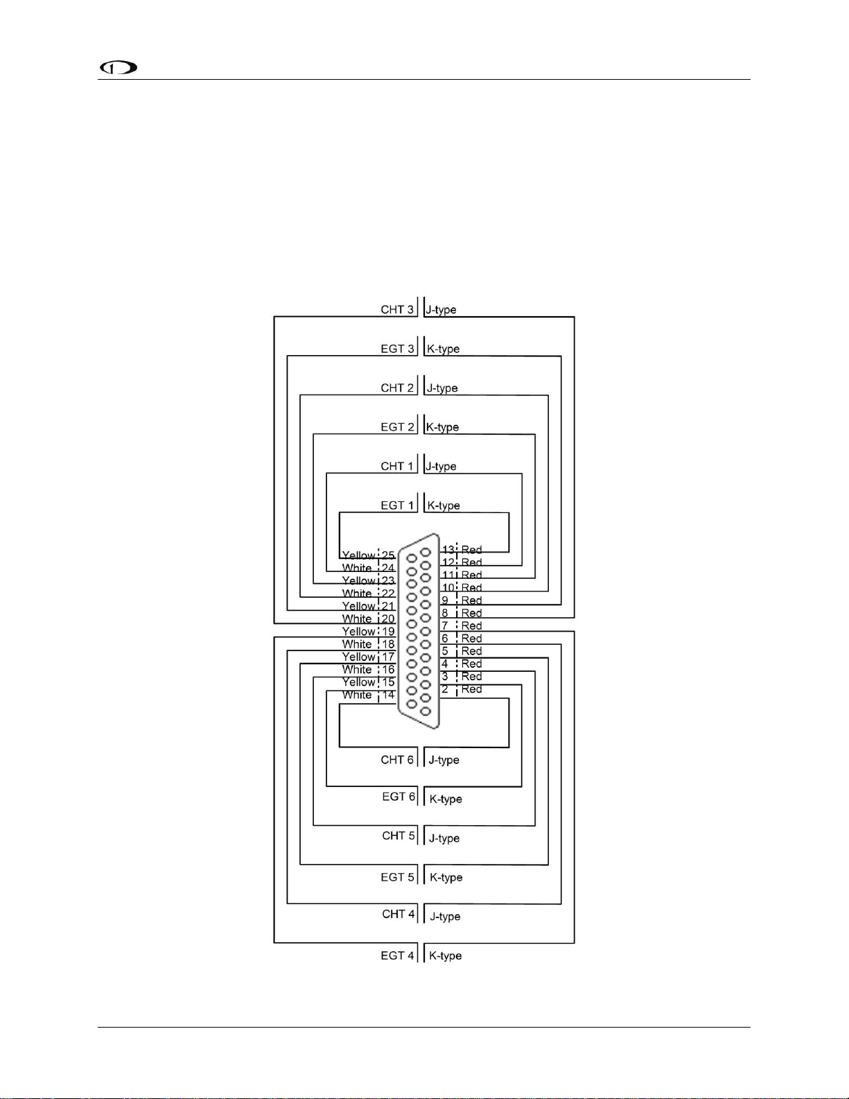
25-Pin Male EMS Harness
Below is the EMS 25-pin harness wiring diagram. The 4-cylinder harness only has EGTs 1
through 4 and CHTs 1 through 4 wired. The Rotax harness only has EGTs 1 and 2 wired, as the
EMS measures the Rotax-supplied resistive CHTs through its GP inputs. On the supplied
harness, each pair of wires is encased in brown insulation and labeled with corresponding
cylinder number. Inside the outer insulations, each wire in the pair has the color listed on the
diagram below. If you are making your own harness, utilize J & K type thermocouple wire as
indicated in the diagram.
FlightDEK-D180 Installation Guide 2-9
Page 18

Page 19

3. TRANSDUCER INSTALLATION
This section explains the steps required to install and connect all transducers supplied by Dynon
Avionics. Additionally, connection instructions are given for some transducers that Dynon
Avionics does not sell, like the tachometer, fuel level, flaps, trim, and contacts.
Tools and Equipment Required
The following list contains commonly used tools and equipment; however some of the tools or
equipment listed below may not apply to your installation.
Wire strippers
22 AWG wire (if harness not purchased or extending harness beyond 6 feet)
D-sub pin crimper
Faston/ring terminal crimp tool
o Available from www.bandcspecialty.com – (316) 283-8000 – part number RCT-1
Weather Pack crimp tool (common slip joint pliers will also work)
o Available from www.whiteproducts.com/tools.shtml
#2 Phillips screwdriver
Flathead screwdriver
¼” ID tubes, any necessary adapters, and clamps for routing manifold pressure to the
sensor.
Drill and 1/8” bit
FlightDEK-D180 Installation Guide 3-1
Page 20

Transducer Installation
Exhaust Gas Temperature (EGT) Probes
Correct placement of EGT probes on the exhaust manifold is critical to obtaining accurate
readings. Placement differs between engine types, and even specific models. Consult your
specific engine’s manual for proper EGT locations.
ROTAX ENGINES
For Rotax 912 engines, only two of the four cylinders are typically monitored for EGT. Unlike
the CHT probes which are mounted on diagonal cylinders, the EGT probes should be mounted
on the two rear cylinders’ exhaust manifolds. It is critical that the EGT probes be mounted to
parallel cylinders’ exhaust manifolds for proper temperature comparison.
ALL ENGINES
Once you have determined the appropriate EGT locations for your engine, drill 1/8” diameter
holes at the specified positions in the exhaust manifold. Usually, this spot is 2 to 8 inches from
the cylinder. This spot should be on a straight portion of the exhaust manifold, as this provides a
better fit for the hose clamps. For best results, mount all probes the same distance from each
cylinder.
1. Make sure the hole is placed to ensure that the probe does not interfere with the cowl or
spark plug. Also, when making holes, keep in mind that the probe could inhibit the ability
to perform routine maintenance if placed incorrectly.
2. Place probe in exhaust manifold, and secure it by tightening the clamp with a flathead
screwdriver. Make sure the clamp is tight and provides a secure fit, but do not over-tighten
such that visible stress is put on the pipe.
Now, plug each thermocouple wire into its corresponding wire on the thermocouple harness.
Ensure that you match the wire color pairs on the harness to those on the thermocouple. All
thermocouple harnesses supplied by Dynon have each function (e.g., CHT1, EGT1) labeled on
each thermocouple pair.
A loose probe could allow exhaust to leak. This can lead to carbon monoxide poisoning
in the cabin and/or a potential fire. Have a knowledgeable mechanic inspect the
installation.
The probe can come lose during flight, and could potentially come in contact with
rotating engine parts or the propeller. We suggest a safety wire to keep the probe in place.
3-2 FlightDEK-D180 Installation Guide
Page 21

Transducer Installation
Cylinder Head Temperature (CHT) Probes
Dynon Avionics sells and supports a variety of CHT probes. All thermocouple harnesses
supplied by Dynon have each function (e.g., CHT1, EGT1) labeled on each thermocouple pair.
LYCOMING/CONTINENTAL
Dynon Avionics sells bayonet style CHT probes (used in Lycoming and Continental engines).
With each probe we sell, a bayonet adapter is included. Your specific engine manual should
describe where to mount these bayonet adapters, but normally, there is a threaded hole (CHT
well) near the bottom of the cylinder close to the lower spark plug. Screw the bayonet adapter
into this hole. Screw the locking collar up or down the spring surrounding the probe such that the
tip of the probe is pressed against the bottom of the CHT well when the collar is attached to the
adapter. Insert the CHT probe into the well and lock the collar to the adapter. Now, plug each
thermocouple wire into its corresponding wire on the thermocouple harness. Ensure that you
match the wire color pairs on the harness to those on the thermocouples.
ROTAX
Rotax 912 engines use 2 resistive CHT probes that are included with the engine. These probes
are preinstalled, but you need to route the connections from them to the FlightDEK-D180. See
the CHT General Purpose Installation section on page 3-15 for information on making the
physical connection to the sensor.
JABIRU
Jabiru engines require a 12mm ring-terminal CHT probe for each cylinder. First, slide the
compression washer off the spark plug. Slide the 12mm ring-terminal probe onto the plug. Now,
slide the spark plug compression washer back onto the spark plug. Reinstall the spark plug into
the spark plug hole. Please refer to the documentation that came with your engine for more
information. Now, plug each thermocouple wire into its corresponding wire on the thermocouple
harness. Ensure that you match the wire color pairs on the harness to those on the thermocouples.
FlightDEK-D180 Installation Guide 3-3
Page 22
Transducer Installation
Tachometer
Dynon Avionics does not sell a tachometer transducer.
Depending upon existing equipment and engine type,
you have a few options for connecting the tachometer
inputs on the FlightDEK-D180. See the relevant
subsections below for your particular method. You may
connect different types of signals to the two different RPM inputs (e.g., p-lead to RPM Left and a
12V transducer to RPM Right). Once you have connected the tachometer inputs according to
your engine and transducer type, you must set the appropriate pulses/revolution as described on
page 6-8.
TACHOMETER TRANSDUCER
If you have a standard tachometer transducer (usually with a 12V output), you may simply
connect its output to the RPM Left input on the FlightDEK-D180. Ensure that you follow all
recommendations given in the manual for your individual tachometer transducer.
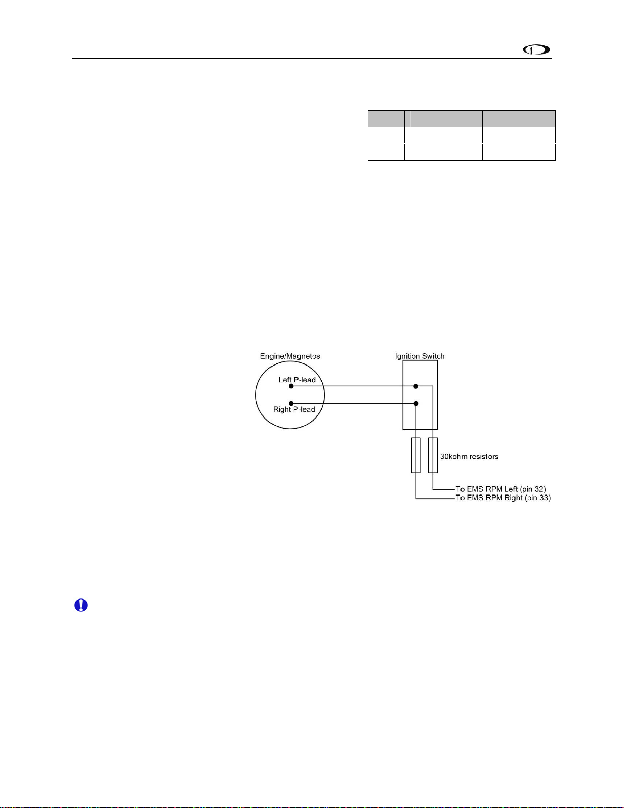
P-LEAD PICKOFF (LYCOMING AND CONTINENTAL)
If you do not have a standard
tachometer pickoff, you must
follow the instructions below. The
magneto P-lead has high voltages
which can very easily damage the
FlightDEK-D180 if not dealt with
properly.
Pin Color Function
32 White/green RPM Left
33 White/blue RPM Right
Use the two included 30kΩ
resistors (color bands: orange,
black, brown, red, brown; connect
in either direction) to attach left
and right P-leads to the RPM Left
and RPM Right inputs on the FlightDEK-D180. Connect them as shown in the following
diagram. It is important to connect each resistor as close as possible to the spot where you tap
into the P-lead. This minimizes the length of cable carrying high voltage spikes. 6 cylinder
Lycoming engines sometimes need more inline resistance to prevent false readings by the
FlightDEK-D180.
If, after setting the PULS/REV R and L values as described on page 6-8, you see higher
than expected RPM or unstable values, you may need to increase the series resistance to
as high as 150kΩ.
TRIGGER COIL (ROTAX)
The Rotax 912 engines have a 5th trigger coil for the purposes of electrically monitoring rev
counts. This trigger coil outputs to a two-wire harness. Connect either of the two wires to
ground; connect the other to one of the included 30kΩ resistors (color bands: orange, black,
3-4 FlightDEK-D180 Installation Guide
Page 23
Transducer Installation
y
brown, red, brown; connect in either direction). Connect the other end of the resistor to the RPM
Left input on the FlightDEK-D180.
ALTERNATOR WIRE (JABIRU)
The most common tachometer pickoff location for Jabiru 2200 and 3300 engines is one of the
alternator wires. Splice a wire off one of the two white alternator wires, connect it through a 1amp fuse to the RPM Left input on the FlightDEK-D180.
DIGITAL IGNITION AND OTHER PICKOFFS
The FlightDEK-D180 can read frequency-based RPM signals, provided the peak voltage is at
least 10 volts above ground. If the peak voltage exceeds 50 volts, use the included 30kΩ resistors
as described in the P-lead Pickoff section above. Like the other methods above, you must know
the number of pulses per revolution for your RPM transducer.
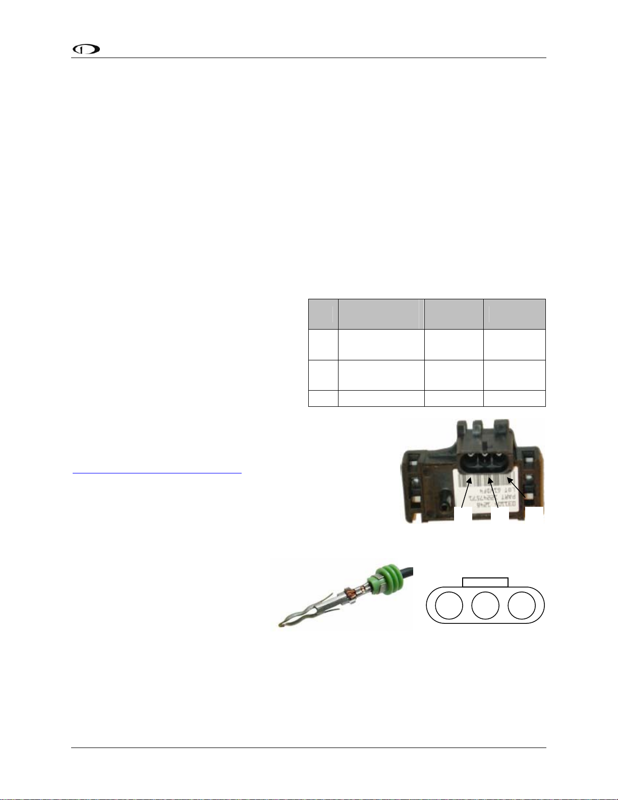
Manifold Pressure Sensor
The manifold pressure sensor is an integral
Pin
assembly consisting of three pins, a rubber
seal, and a connector housing. Strip 3/16”
18 C White/red
insulation off the ends of the three wires
listed at right. Slide the three rubber seals
26 B Green/red
onto the three wires and the pins onto the
ends of the wires. Crimp the 3 provided pins
17 A Black Ground
onto the ends of the wires, ensuring that the
long tabs that cradle the rubber seal wrap
around the seal (see picture at right for example). For more
details on preparing and crimping the Weather Pack pins, see
www.whiteproducts.net/faqs.shtml.
Weather
Pack Pin#
Color Function
+5V
excitation
Manifold
pressure
Note that you will need access to the +5V excitation circuit for
other sensor installations, so make allowances for breaking out
the connection to other areas. Route the three wires to the
C
B A
location where you would like to mount the manifold pressure
sensor.
Figure 1 Connection diagram for
sensor with all black wires only
Plug the crimped pins into the
provided Weatherpack connector.
Now, mount the manifold pressure
sensor in a secure fashion using the
C
B A
mounting holes on either side of the
sensor.
The pressure port on the manifold
pressure sensor requires 1/4” inner
Figure 3: Detail view of properl
crimped pin.
Figure 2: Pin insertion
(rear) view of supplied
connector.
diameter tubing for a secure fit. You may need to use adapters to
convert down to smaller inner diameter tubing for your specific engine. We recommend that you
use pipe clamps at every transition point, including at the sensor itself.
FlightDEK-D180 Installation Guide 3-5
Page 24
Transducer Installation
If you notice fluctuations on the manifold pressure reading on the FlightDEK-D180, you may
need to install a restrictor with a small hole inline between the sensor and the head where the
manifold pressure line is split off.
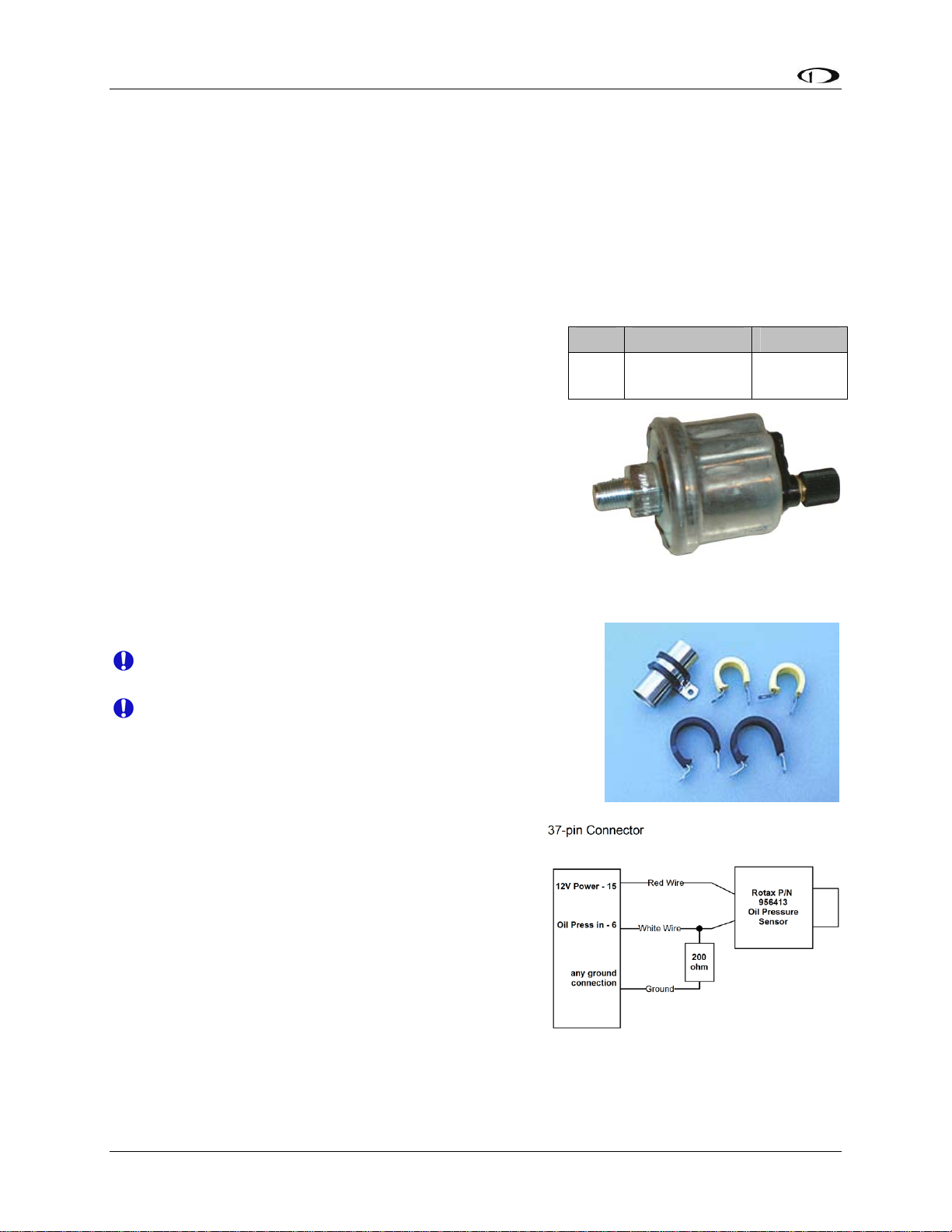
Oil Pressure Sensor
The FlightDEK-D180 supports several oil pressure sensor installations. The Dynon-supplied
sensor and the Rotax and Jabiru pre-installed sensors are the most common.
DYNON-SUPPLIED OIL PRESSURE SENSOR
First, mount the oil pressure sensor to a fixed location
using an Adel clamp (see picture at lower right) or other
secure method. The oil pressure sensor must not be
installed directly to the engine due to potential vibration
problems. Dynon Avionics’ sensor is supplied with a
1/8” NPT pipe thread fitting. An adapter might be necessary
for some engines. Please see the manual supplied by the
engine’s manufacturer. You must use appropriate pipe fitting
adapters and ensure that the case of the sender has a
connection to ground. This is critical for functionality.
Crimp a standard #8 ring terminal onto the white/yellow wire
from pin 6. Unscrew the stud cap from the threaded stud.
Place the ring terminal on the stud and secure the cap down
sandwiching the ring terminal.
Due to vibration issues, never connect the sensor
directly to the engine.
If you use Teflon tape or other seal, ensure the sensor
casing still maintains a good connection to ground.
JABIRU AND ROTAX OIL PRESSURE
Pin Color Function
6 White/yellow
1/8-27 NPT
0-150 PSI
Oil
pressure
If you are installing on a Jabiru or Rotax engine, your engine
comes with a pre-installed oil pressure sensor.
Prior to mid-2008, Rotax provided an oil pressure
sensor with 2 tabs for electrical connection. In mid2008, Rotax switched to a new type of oil pressure
sensor (Rotax P/N 956413) with an integrated 2-wire
cable. Connect this newer sensor according to the
wiring diagram at right. Connect the red wire of the
new sensor to EMS DB37 Pin 15 (12V). Connect the
white wire of the new sensor to EMS DB37 Pin 6.
Then, connect one end of a 200Ω resistor to pin 6,
and the other end to ground. The Jabiru and both types of Rotax oil pressure sensors are
compatible with the FlightDEK-D180. Select the correct sensor type as described in the Oil
Pressure Configuration section on page 6-9.
3-6 FlightDEK-D180 Installation Guide
Use an Adel clamp similar to the
above to secure the pressure sensor
Page 25
Transducer Installation
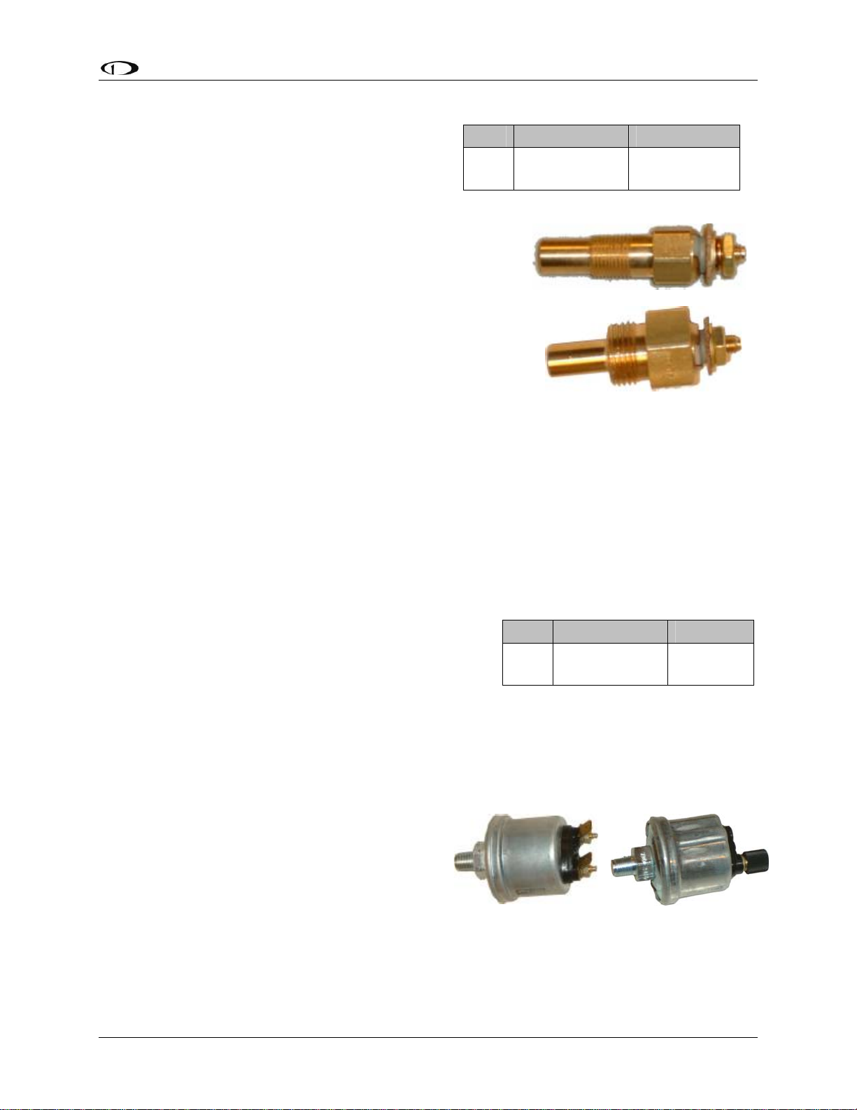
Oil Temperature Sensor
The oil temperature sensor needs to be installed
according to the directions of the engine
manufacturer. Dynon Avionics sells oil
temperature sensors with both 5/8-18 UNF
(Dynon P/N 100409-001) and 1/8-27 NPT
(Dynon P/N 100409-000) threads. Ensure that you have the
right sensor for your engine. Using a crush washer (not
provided) between the sensor and the engine case, tighten the
sensor according to your engine manufacturer’s
recommendations.
Route the wire from pin 7 on the 37-pin harness to where the
oil temperature sensor is mounted. When routing the wires,
make sure that they are secured, so they will not shift position
due to vibration. Strip ¼” of insulation off the end of the w
Crimp a #10 ring terminal onto the end of the wire, ensuri
that a good connection is made between the wire and the connector. Unscrew the nut from the
stud on the oil temperature sensor. Slip the ring terminal onto the stud and secure the nut over i
Pin Color Function
7 White/brown
1/8-27 NPT
ire.
5/8-18 UNF
Oil
Temperature
ng
t.
As mentione
susceptible to voltage differences between the en
d in the Grounding section on page 2-2, the oil temperature sensor is very
gine case and the negative terminal of the
battery. Ensure that solid, thick, and short electrical connections exist between the engine an
battery ground.
Fuel Pressure Sensor
First, mount the fuel pressure se
using an Adel clamp or other secure method. The fuel
pressure sensor must not be installed directly to the
engine due to potential vibration problems. Next,
connect the fuel sensor to the engine using approp
hoses and fittings. Its pressure port has a 1/8-27 NPT pi
to connect to the pressure port on your engine. Locate the correct fuel pressure port for your
engine. This port must have a pressure fitting with a restrictor hole in it. This restrictor hole
ensures that, in the event of a sensor failure, fuel leakage rate is minimized, allowing time fo
emergency landing.
Carbureted engines
: Use the 0-30 PSI sensor
(Dynon P/N 100411-000). Crimp a standard ¼”
female Faston onto one of the ground wires (see
the Grounding section on page 2-2) coming from
the 37-pin harness. Crimp another ¼” fe
Faston onto the brown wire from pin 8. Push t
two Fastons onto the two terminals on the fuel
pressure sensor. Polarity is not important. If you
nsor to a fixed location
riate
male
he
Pin Color Function
8 Brown
Fuel
Pressure
pe thread fitting; you may need adapters
1/8-27 NPT
0-30 PSI
1/8-27 NPT
0-80 PSI
d
r an
FlightDEK-D180 Installation Guide 3-7
Page 26

Transducer Installation
are converting from a GRT EIS system, you must disconnect the external resistor pull-up from
the fuel pressure output. This will make the sensor output equivalent to the sensor supplied by
Dynon Avionics.
Injected engines: Use the 0-80 PSI sensor (Dynon P/N 100411-001). Crimp a standard #8 ring
terminal onto the brown wire from pin 8. Unscrew the stud cap from the threaded stud. P
ring terminal on the stud and secure the cap down sandwiching the ring terminal. If the
connection between the sensor and your engine is non-metallic, you must connect the sensor c
to ground through other means. The best way to accomplish this is b
connected ring terminal between the sensor and the mating fitting.
y sandwiching a ground-
lace the
ase
Due to vibration issues, never connect the sensor directly to engine.
If you use Teflon tape or other seal, ensure the sensor casing still maintains a good
connection to ground.
3-8 FlightDEK-D180 Installation Guide
Page 27
Transducer Installation
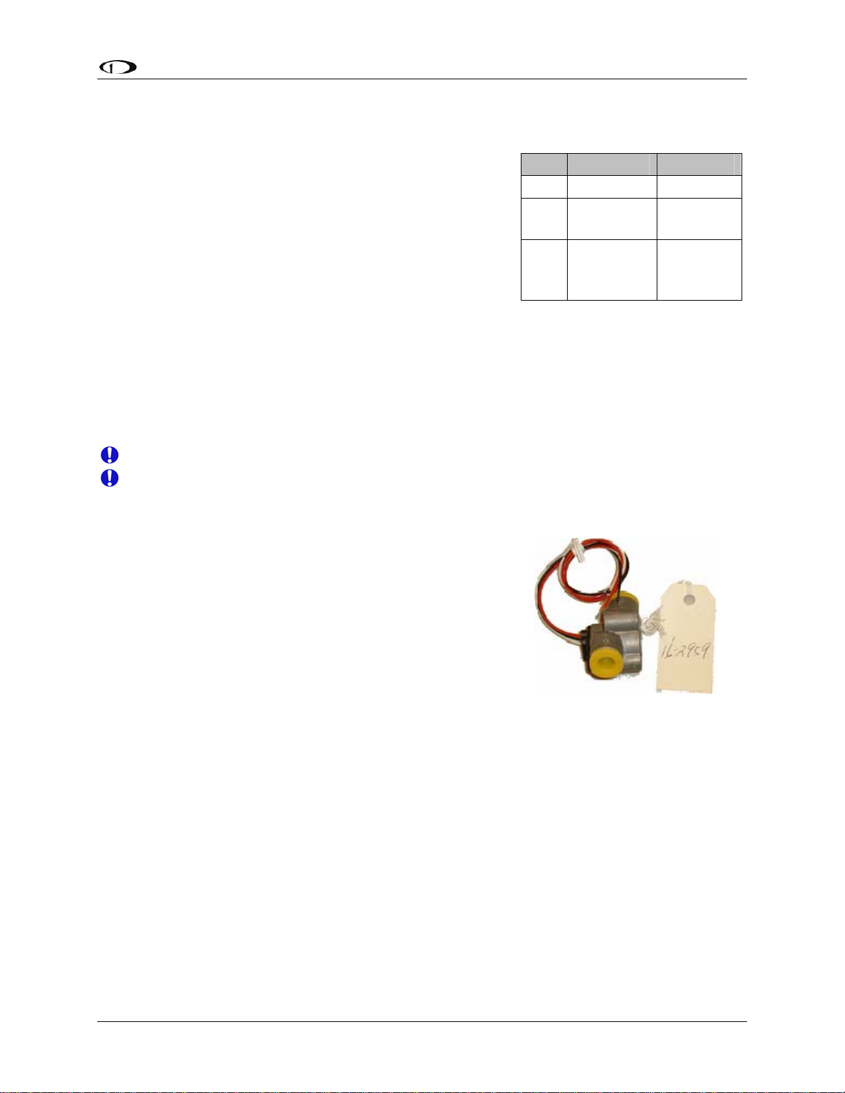
Fuel Flow Sensor
Dynon Avionics supplies two different fuel flow
transducers:
Floscan 201B (Dynon P/N 100403-001)
Electronics International FT-60 (Dynon P/N 100403-
003)
GENERAL PLACEMENT RECOMMENDATIONS
When placing either sensor, ensure that the three wire leads
are pointed straight up. A filter should be placed upstream from the sensor to screen out debris.
Placement of the fuel flow sender relative to other items in the fuel system like fuel pumps is left
to the builder. The manufacturer of the fuel flow sender does not make strong recommendations
on this point. It is not uncommon, though, to place the sender downstream of any auxiliary
electric boost pumps but upstream of the engine driven fuel pump. For best measuring
performance, the fuel should travel uphill by one to two inches after leaving the fuel flow sender.
Pin Color Function
13 Black Ground
Yellow (or
14
15 Red
white)
Fuel flow
input
Fuel flow
power
(14V)
Due to vibration issues, never connect the sensor directly to engine.
Do NOT use Teflon tape when screwing in any of the fittings.
FLOSCAN TRANSDUCER INSTALLATION
The FloScan fuel flow transducer has ¼” female NPT threads
at both the inlet and outlet. Only use ¼” NPT fittings to match.
When installing, do not screw fittings more than two full turns
past hand tightened. The torque should not exceed 180 inchlbs.
¼” NPT Female
Make note of the numbers on the tag attached to the fuel
flow sensor. You will need it in the Fuel Flow Configuration
section on page 6-14.
EI “RED CUBE” INSTALLATION
The Electronics International “Red Cube” FT-60 flow transducer has ¼” female NPT ports. Do
not exceed a torque of 300 inch-lbs when installing fittings into the transducer. The fuel line on
the outlet port should not drop down after exiting the transducer. This configuration can trap
bubbles in the transducer, causing jumpy readings.
The inlet port, outlet port, and flow direction are marked on the top of the FT-60.
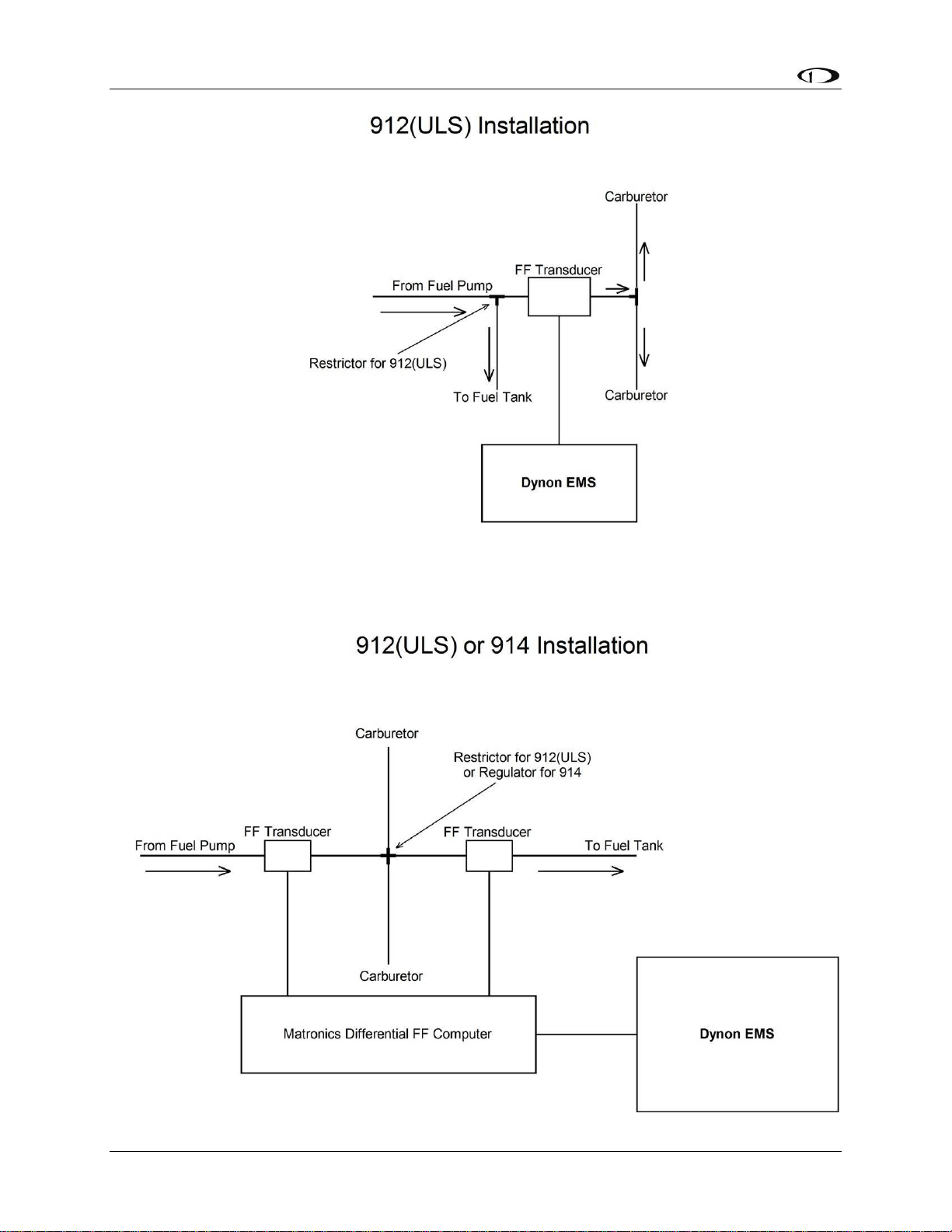
ROTAX PLACEMENT RECOMMENDATIONS
If installing on a Rotax 912, review the following page for recommendations specific to these
engines.
FlightDEK-D180 Installation Guide 3-9
Page 28
Transducer Installation
3-10 FlightDEK-D180 Installation Guide
Page 29
Transducer Installation
Fuel Level Sensor
Dynon Avionics does not sell fuel level sensors.
The FlightDEK-D180 supports both resistive type
sensors as well as capacitive sensors which output a
voltage (e.g., Princeton). If you have a capacitive
sensor which does not output a voltage on its own,
you may be able to use Dynon’s Capacitance-toVoltage Converter. Read the relevant section below
for the type that you are installing.
Once you have installed your fuel level sensors, you
will need to calibrate each of them, as described in
Fuel Level Calibration on page 6-5.
RESISTIVE FUEL LEVEL SENSOR
Pin Color Function
Fuel level 1
20 Orange/brown
(resist or
cap)
Fuel level 2
21 Orange/blue
(resist or
cap)
See General Purpose Inputs section
4 Purple/blue GP 1
22 Purple/yellow GP 2
23 Purple/green GP 3
You may connect up to four resistive fuel level sensors to the FlightDEK-D180. Simply connect
the output of the sensor you would like to be Fuel Level 1 (left tank) to pin 20 and the sensor you
would like to be Fuel Level 2 (right tank) to pin 21. You may also connect third and fourth fuel
level transducers to the general-purpose inputs of your choice. See the General Purpose Inputs
section on page 3-13 for more information.
CAPACITIVE FUEL LEVEL SENSOR
Capacitive fuel level sensors are only supported on the Fuel Level 1 and Fuel Level 2 inputs.
Additionally, your capacitive sensor needs to output a variable voltage within the ranges of 05Vdc. First, supply the sensor with power according to the manufacturer’s instructions. If the
sensor manufacturer requires a sensor calibration, perform that calibration first. Connect the
sensor’s output to pin 20 or 21, depending on whether you want the tank to display as left (Fuel
Level 1) or right (Fuel Level 2) tank. Do not connect capacitive fuel level sensors to any of the
general-purpose inputs. Be sure to configure the firmware to recognize the capacitive fuel level
sensor on the fuel level input(s) you’ve chosen as described in the Fuel Level Configuration
section on page 6-13.
If you are installing Dynon’s Capacitance-to-Voltage Converter (most commonly used with the
capacitive plates in some RVs), please read Capacitance-to-Voltage Converter Installation on
page 9-35.
FlightDEK-D180 Installation Guide 3-11
Page 30
Transducer Installation
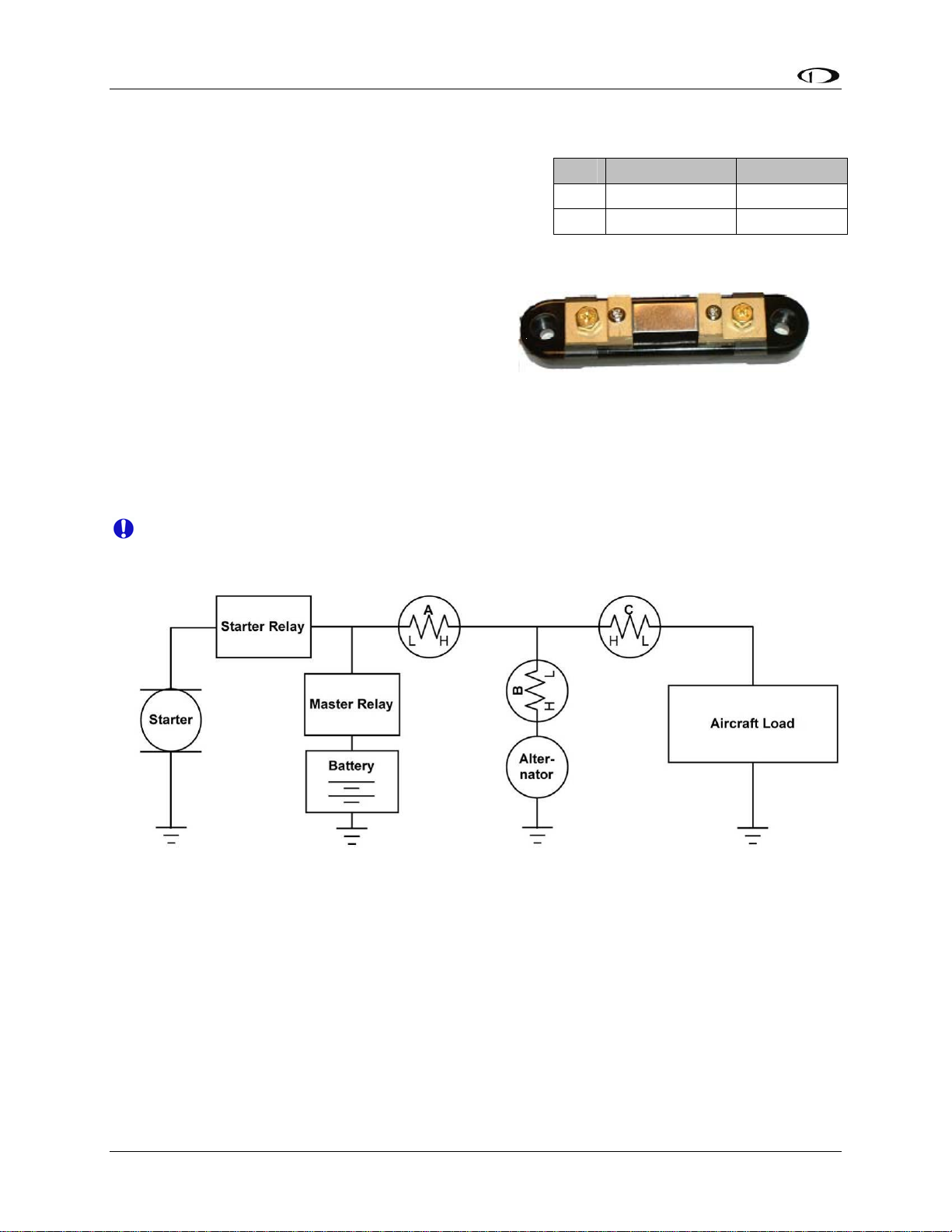
Ammeter Shunt
The ammeter shunt should be mounted so that the metal
part of the shunt cannot touch any part of the aircraft.
The ammeter shunt can be installed in your electrical
system in one of three locations as shown in the
(simplified) electrical diagram below.
Position A: Ammeter indicates current flow into
or out of your battery. In this position, it will
show both positive and negative currents. (-60A
to 60A)
Position B: Ammeter indicates only the positive currents flowing from the alternator to both
the battery and aircraft loads. (0A-60A)
Position C: Ammeter indicates the current flowing only into the aircraft loads. (0A-60A)
Note that the ammeter shunt is not designed for the high current required by the starter and must
not be installed in the electrical path between the battery and starter.
Pin Color Function
24 Orange/green amps high
25 Orange/purple amps low
Electrically, the shunt should be placed so that it does not receive power when the master
switch is off. If it does receive power in this case, it is possible for your aircraft battery to
slowly discharge over a few weeks or months.
Use two ¼” ring terminals sized appropriately for the high-current wire gauge you will be
routing to and from the ammeter shunt. Cut the wire where you would like to install the ammeter
shunt. Strip the wire and crimp on the ring terminals. Using a Phillips screwdriver, remove the
two large screws (one on either end of the shunt), slip the ring terminals on, and screw them back
into the base.
We highly recommend that you fuse both the connections between the shunt and the FlightDEKD180. There are two methods for accomplishing this. You may simply connect two 1 amp fuses
in-line between the shunt and the FlightDEK-D180. Or, you may use butt splices to connect 1” to
2” sections of 26 AWG wire between the shunt and each of the Amps leads connecting to the
3-12 FlightDEK-D180 Installation Guide
Page 31

Transducer Installation
FlightDEK-D180. These fusible links are a simple and cost-effective way to protect against
short-circuits.
Next, crimp the two supplied #8 ring terminals onto the wires using the fusing method chosen
above. Connect the other ends of the fuses to the Amps High and Amps Low leads (pins 24 and
25) on the 37 pin harness. Unscrew the two smaller screws on the ammeter shunt. Slide the ring
terminals onto them and screw them back into the base. Connect the “Amps High” lead to the
side of the shunt marked by “H” in the diagram above; connect the “Amps Low” lead to the side
marked by “L”.
If you find that the current reading on the FlightDEK-D180 is the opposite polarity of what you
want, swap the two signal inputs (Amps High and Amps Low) to obtain the desired result.
It is extremely important that you secure all loose wires and ensure that exposed
terminals cannot touch or short out to other objects in the plane. All metal on the shunt is
at the same voltage as – and carries the same risks as – the positive terminal on the
battery. Improperly installing the ammeter shunt can result in high current flow, electrical
system failure, or fire.
If you are using GRT’s Hall effect amps transducer (P/N CS-01), route its output to pin 24, the
Amps High input, on the 37-pin EMS connector.
General Purpose Inputs
Dynon Avionics supports many sensors for which the
FlightDEK-D180 does not have dedicated inputs. The
instrument has 3 GP (general-purpose) inputs which
can be used for a variety of sources.
OUTSIDE AIR TEMPERATURE SENSOR
Note that this section only applies to the OAT with 2
wires (both colored black/white), for
connection to the EMS DB37 connector. If
you have the 3-wire OAT, see Dynon EFIS
OAT Probe Installation and Usage on page 9-
7. Alternatively, you may still use the 3-wire
OAT on the EMS DB37 connector by ignoring
the red wire and connecting the yellow and
blue wires (irrespective of polarity)
same way as the black/white wires described
here.
Mount Location
It is important that the OAT probe be mounted somewhere on the skin of the aircraft where it
will not be affected by heat sources (sun, engine, aircraft interior, etc). The ideal location would
receive no heat from the aircraft engine or any other source in the aircraft body. While this may
be impractical, it is a good idea to mount the probe as far away from heat sources as possible. On
in the
Pin
Desired
GP
input #
Ground
pin
Pin Color Function
4 Purple/blue GP 1
22 Purple/yellow GP 2
23 Purple/green GP 3
EMS
harness
Color
See chart
above
Black
OAT
sensor
color Function
Black/
White
Black/
White
GP
ground
FlightDEK-D180 Installation Guide 3-13
Page 32
Transducer Installation
the RV series, common locations include the wingtip and under the horizontal stabilizer. Avoid
these three locations:
Engine exhaust paths
The engine itself
Where the sensor will have direct sunlight
Where the backside is exposed to a heated cabin
Mounting Instructions
After the mounting location has been determined, drill a 3/8” hole in the skin at the desired
location. Uncoil the cable attached to the OAT probe. Remove the nylon nut from the cable.
From outside the skin of the aircraft, insert the cable first and then the threaded end of the OAT
probe. From within the skin of the aircraft, gently pull the cable until the threaded end of the
OAT probe pokes through the hole. Thread the nylon nut down the cable and up to the threaded
end of the OAT probe. Spread some Loctite around the threads of the OAT probe. Twist the nut
onto the threads of the OAT probe and tighten.
Wiring Instructions.
Once you have physically mounted the OAT probe, route its attached cable to the FlightDEKD180. Connect one of the black/white wires to ground, either at a supplied connection on the 37pin harness or at another convenient location. If using the EFIS 3-wire OAT simply route either
the yellow or blue wire to ground.
Connect the other black/white wire on the OAT probe to the desired GP input on the FlightDEKD180 main harness. Again, if using the EFIS 3-wire OAT simply route either the yellow or blue
wire (whichever did not get routed to ground) to the desired GP input. When routing wires for
this sensor, try to keep wires away from radios, ignition, or other electronics.
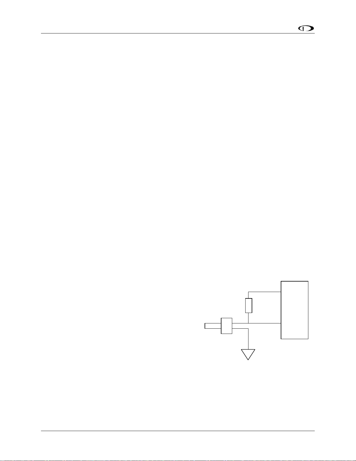
CARBURETOR TEMPERATURE SENSOR
Install the carburetor temperature sensor in the venturi
area at the point where ice first begins to form. This is
located after the main nozzle, before the throttle valve.
You must remove the plug in the carburetor housing
1kΩ
+5V
ex
citation
below the throttle valve. On 4-cylinder engines which
use the Marvel Schebler MA-3 carburetors, this plug is
GP in
located on the forward side. On 6-cylinder engines
using the MA-4 carburetor, the plug is located on the
rear. If your carburetor is not drilled and tapped for the
plug, you must remove the carburetor from the engine
and drill out the lead plug in the appropriate spot. Tap
the hole with a ¼-28 tap. Remove all chips and burrs
before reinstalling.
Connection for all black wire sensor
(P/N 100413) only. No resistor needed
for black/white wire sensor (P/N
Route either of the two wires to an electrical ground.
100468).
Route the other wire to the general-purpose input of
your choice. If you received a temperature sensor with all black wires (Dynon P/N 100413), you
3-14 FlightDEK-D180 Installation Guide
Page 33
Transducer Installation
should find a 1kΩ resistor (color bands: brown, black, black, brown, brown; connect in either
direction) in the package. Connect one end of this resistor to the +5V Excitation Circuit (pin 18)
and the other end to the GP input you’ve connected the sensor to. If you received a sensor with
black/white wires (Dynon P/N 100468), there will be no resistor in the package and you do not
need to make any additional connections.
Be sure to configure the FlightDEK-D180 to recognize the carburetor temperature sensor on the
general-purpose input you’ve chosen as described in the General Purpose Inputs section on page
6-16.
FUEL LEVEL (RESISTIVE) SENSORS
You may connect up to two resistive fuel level sensors to the GP inputs. Generally, this should
only be done if the plane has more than two tanks and the dedicated fuel level inputs are already
used. Connect the output of the fuel level sensor to the desired GP input. Also, connect this same
node to a 200Ω resistor (color bands: Red, black, black, black, brown; connect in either
direction); the other end of which should be attached to the +5V Excitation Circuit. (Resistor
values between 150Ω and 300Ω can be used if 200Ω is not readily available.)
Be sure to configure the firmware to recognize the fuel level sensor on the general-purpose
input(s) you’ve chosen as described in the General Purpose Inputs section on page 6-16.
ROTAX CHT SENSORS
Crimp bare ¼” female Faston terminals
(6.3x0.8 according to DIN 46247) onto the
ends of the wires connected to GP 1 (pin 4)
and GP 2 (pin 22) on the FlightDEK-D180.
Pin Color Sensor Function
4 Purple/blue CHT L GP 1
22 Purple/yellow CHT R GP 2
Locate the left-side CHT sensor screwed into
the bottom side cylinder head 2; slide the Faston
connected to GP1 input onto it. Locate the left-side
CHT sensor screwed into the bottom side cylinder head
1.21kΩ
+5V
citation
ex
3; slide the Faston connected to GP2 input onto it.
You will find two 1.21kΩ resistors (color bands: brown,
GP in
red, brown, brown, brown; connect in either direction)
in the accessories package (Dynon P/N 100446-000)
included with the FlightDEK-D180. Connect either end
Case
grounded
of one of the resistors to the +5V Excitation Circuit (pin
18) and the other end to the wire connecting the left
CHT sensor to pin 4. Repeat this with the right CHT sensor.
Be sure to configure the FlightDEK-D180 to recognize the Rotax CHT sensors on the 2 generalpurpose inputs as described in the General Purpose Inputs section on page 6-17.
FlightDEK-D180 Installation Guide 3-15
Page 34
Transducer Installation
TRIM AND FLAPS POSITION POTENTIOMETERS
Dynon Avionics does not sell trim or flaps
position sensors. These are normally included
with, or added on to, their respective servos.
Most flap and trim sensors are potentiometers
(variable resistors) which require power and
ground inputs, and supply an output that is a
function of position. These potentiometers
come in a variety of resistance ranges, but are
typically 1kΩ, 5kΩ, 10kΩ, and 20kΩ. All of
these values will work properly with the
FlightDEK-D180, as there is a calibration
required, as described on page 6-6. Connect
the 5V Excitation line from the FlightDEK-
DB37
EMS
Pin
Desired
GP
input #
EMS
harness
Color
See chart
on page 3-
13
Position
Pot
Function Function
Position
out
(voltage)
18 White/Red +5V in
Ground
pin
Black
Ground in
(common
to EMS)
GP
Position
sensor
power
ground
D180 37-pin EMS connector to the +5V input
on your trim/flap position sensor. Connect the
ground input on the sensor to a ground common to the FlightDEK-D180. Connect the output of
the sensor to the desired GP input. You may connect up to three trim/flap sensors. For physical
installation, refer to the instructions that came with your position sensor.
If you are using the output from a Ray Allen servo or sensor, connect its white/orange wire to the
Dynon 5V excitation line (pin 18), its white/blue wire to ground, and its white/green wire to your
GP input of choice.
Be sure to configure the FlightDEK-D180 to recognize the various sensors on the generalpurpose inputs as described in the General Purpose Inputs section on page 6-17. Additionally,
you will need to calibrate each flap/trim sensor as described on page 6-6.
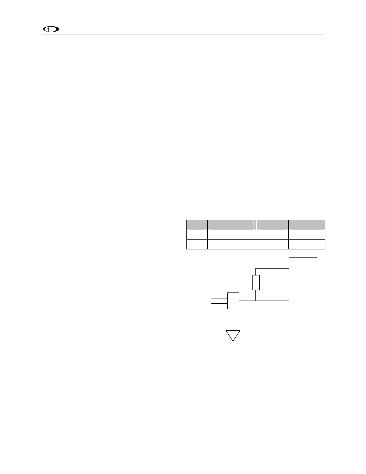
COOLANT PRESSURE SENSOR
You will find two 1kΩ resistors (color bands:
brown, black, black, brown, brown; connect in
either direction) in the accessories package (Dynon
P/N 100446-000) included with the FlightDEKD180. You will be using one of these resistors for
proper installation of this sensor.
The Dynon-supplied coolant pressure sensor is a 030 psi sensor (Dynon P/N 100411-000). First,
mount the pressure sensor to a fixed location using
an Adel clamp or other secure method. The
pressure sensor must not be installed directly to the
engine due to potential vibration problems. Next,
EMS
DB37
Pin
Desired
GP input
#
EMS harness
Color
See chart on
page 3-13
18 White/Red
Ground
pin
Black
Function
GP
5V supply
to 1kΩ
resistor
Ground in
(common
to EMS)
connect the sensor to the coolant line using
appropriate hoses and fittings. Its pressure port has
a 1/8-27 NPT pipe thread fitting; you may need adapters to connect to the pressure port on your
engine. Locate (or drill and tap) the pressure port along the coolant line. This port must have a
3-16 FlightDEK-D180 Installation Guide
Page 35
Transducer Installation
pressure fitting with a restrictor hole in it. This restrictor hole ensures that, in the event of a
sensor failure, coolant leakage rate is minimized, allowing time for an emergency landing.
Crimp a standard ¼” female Faston onto one of the
ground wires (see the Grounding section on page 2-2)
ing from the 37-pin harness. Crimp another ¼”
com
female Faston onto both the wire that corresponds to the
1kΩ
+5V
excitation
desired GP input and a 1kΩ resistor (color bands:
brown, black, black, brown, brown; connect in either
direction), or splice the resistor into the GP input line
GP in
elsewhere on the run. Push the two Fastons onto the two
terminals on the fuel pressure sensor. Polarity is not
important. Connect the other side of the 1kΩ resistor
(color bands: brown, black, black, brown, brown;
connect in either direction) to the 5V Excitation Circuit, pin 18, as shown in the diagram.
Due to vibration issues, never connect the pressure sensor directly to engine.
If you use Teflon tape or other seal, ensure the sensor casing still maintains a good
connection to ground.
COOLANT TEMPERATURE SENSOR
You will find two 1kΩ resistors (color bands: brown,
black, black, brown, brown; connect in either direction)
in the accessories package (Dynon P/N 100446-000)
included with the FlightDEK-D180. You will be using
one of these resistors for proper installation of your
coolant temperature sensor.
The coolant temperature sensor needs to be installed
according to the directions of your engine’s
manufacturer. Dynon Avionics sells temperature sensors
with both 5/8-18 UNF (Dynon P/N 100409-001) and 1/8-
EMS
DB37
Pin#
Desired
GP input
#
EMS
harness
Color
See chart on
page 3-13
18 White/Red
Functio
n
GP
5V
supply
to 1kΩ
resistor
27 NPT (Dynon P/N 100409-000) threads; these are the
same as those used by the oil temperature inputs. If
neither of these threads matches those in your coolant
line, you will need to use adapters or drill/tap your own.
Using a crush washer between the sensor and the mating
line, screw the sensor into the fitting. Do not over
1kΩ
+5V
excitation
tighten.
Route the wire from the desired GP pin on the 37-pin
GP in
harness to where the coolant temperature sensor is
mounted. When routing the wires, make sure that they
are secured, so they will not shift position due to
Case
grounded
vibration. Strip ¼” of insulation off the end of the wire.
Crimp a #10 ring terminal onto the end of the wire and a
1kΩ resistor (color bands: brown, black, black, brown, brown; connect in either direction), or
splice the resistor into the GP input line elsewhere on the run. Ensure that a good connection is
FlightDEK-D180 Installation Guide 3-17
Page 36
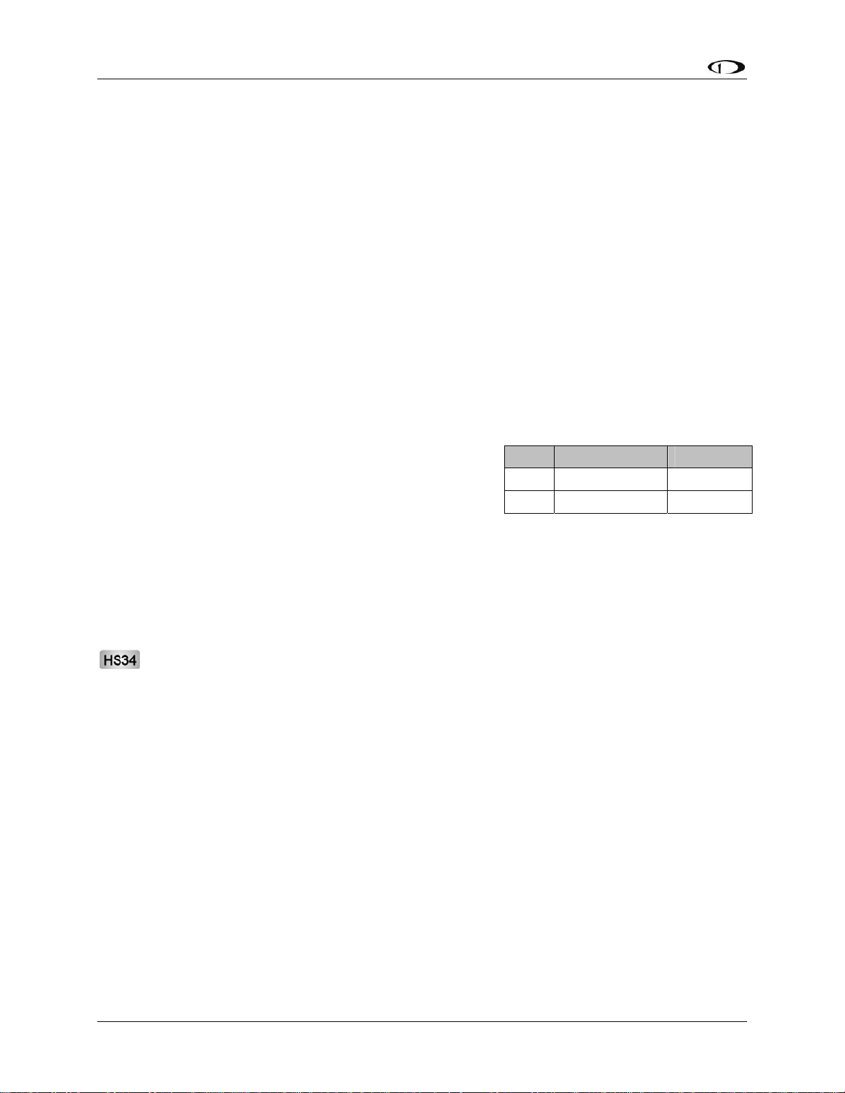
Transducer Installation
made between the wire and the connector (and resistor, if spliced in at that point). Unscrew the
nut from the stud on the coolant temperature sensor. Slip the ring terminal onto the stud and
secure the nut over it. Connect the other side of the 1kΩ resistor (color bands: brown, black,
black, brown, brown; connect in either direction) to the 5V Excitation Circuit, pin 18, as shown
in the diagram.
Rotax Pre-installed Coolant Temperature Sensor: Wire the coolant temperature sensor in the
same way as shown above for the Dynon-supplied sensor. Configure the Sensor Type as 4, as
shown on page 6-17.
GENERAL PURPOSE TEMPERATURE SENSOR
You may connect an OAT probe and configure it as a general purpose temperature measurement
(e.g., for cabin temperature). Refer to the Outside Air Temperature Sensor section on page 3-13
for installation information and to the General Purpose Temperature section on page 6-18 for
configuration information.
Contacts
Dynon Avionics does not sell contacts or switches.
Contacts are used for a variety of purposes, such as
monitoring canopy closure. The EMS firmware reads
the state of two contact inputs, reporting whether each
input is open (no connection to ground) or closed
(connection to ground). You may connect up to two contacts you would like to be monitored by
the FlightDEK-D180. You must ensure that when closed, the contact connects to a ground
common to the FlightDEK-D180. The voltage on the contact inputs must not exceed 15V.
The Contacts Configuration section on page 6-18 describes the details of configuring the
contacts, including giving them custom names.
Pin Color Function
9 Brown/blue Contact 1
10 Brown/yellow Contact 2
If more than two contacts are needed, the optional HS34 includes four additional
contacts. Connection and configuration of HS34 is the same as for contacts connected
directly to the FlightDEK-D180.
3-18 FlightDEK-D180 Installation Guide
Page 37

Transducer Installation
General Purpose Thermocouple
You may configure the FlightDEK-D180 to monitor one J
or K type thermocouple. Dynon Avionics does not supply a
specific general purpose thermocouple probe for this
purpose. However, our standard EGT and CHT probes will
work, as will any other J or K type thermocouple.
Dynon Avionics sells both J and K type thermocouple wire
which may be used to connect the desired thermocouple to
the FlightDEK-D180. Ensure you order the correct wire
type for the thermocouple you intend to use. Crimp a female D-sub pin on the end of each wire,
and plug them into the D37 connector. Polarity is important, so ensure that you are routing the
positive side (yellow for K-type; white for J-type) of the thermocouple to pin 27 on the 37-pin
harness, and the negative side to pin 28.
Pin Color Function
Thermocouple
+ (yellow or
white)
Thermocouple
– (red)
27
28
Not
supplied
Not
supplied
FlightDEK-D180 Installation Guide 3-19
Page 38

Page 39
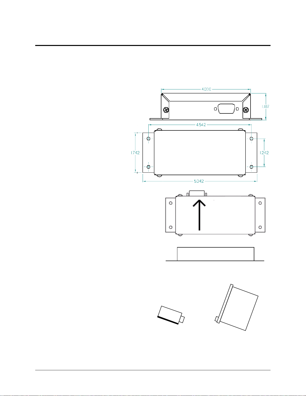
4. INSTRUMENT INSTALLATION
This section provides you with the information needed to physically and electrically install the
FlightDEK-D180.
Selecting a Remote Compass Module Location
Finding a good location for the EDC-D10A
remote compass module is critical to an
accurate FlightDEK-D180 heading display.
Keep in mind that calibration can
compensate for small static magnetic fields
superimposed upon the earth’s field;
it cannot take into account dynamic
effects like AC currents, nonconstant DC currents and nonstationary ferrous material (e.g., an
electric turn coordinator). Use the
following suggestions to help you
find a good location for your EDCD10A.
Keep the EDC-D10A away from
any source of magnetic fields (such as
electrical equipment and current-carrying
wires) and ferrous material.
Move a handheld compass throughout the
space surrounding your location to get a r
idea of the suitability of your chosen location
If the needle deviates significantly from
magnetic north in any given area, that locatio
would not be ideal for the EDC-D10A.
The ED
the aircraft (away from magnetic interference)
such that its pitch is as close to that of the
FlightDEK-D180 as possible. It does not
need to be directly along any axis of the
FlightDEK-D180. It should be mounted
with the long axis parallel to the wings, the
electrical connector facing toward the front
of the plane, and the mounting tabs on the
bottom. The bracket used to hold the EDCD10A must hold the EDC-D10A at the
same pitch, roll, and yaw as the FlightDEKD180 with respect to the airframe. We
recommend that you use an electronic level,
C-D10A can be mounted anywhere in
Connector toward
direction of flight
ough
.
n
Connector forward and
tabs mounted down
Side view of EDC-D10A, tabs mounted
d own and aligned within 1 degree of pitch
with FlightDEK-D180
FlightDEK-D180 Installation Guide 4-1
Page 40
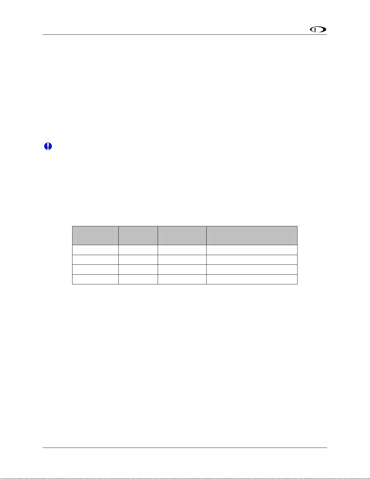
Instrument Installation
if available, to make sure the EDC-D10A is aligned with the FlightDEK-D180 to better than
1 degree.
All mounting hardware needs to be made from non-ferrous material such as aluminum,
plastic, or brass. Many stainless steel screws are magnetic. If the item is attracted to a
magnet, it should not be used in the installation. The EDC-D10A needs to be mounted in a
location as free from magnetic interference as possible. This means keeping the EDC-D10A
away from any ferrous nuts, bolts, and screws, aircraft tubing, as well as from wires or
devices carrying any appreciable current such as strobe light wiring, autopilot servos, or
other electronics.
EDC-D10A Communication Cable
DO NOT ATTEMPT TO POWER UP THE FlightDEK-D180 WITH THE EDC CABLE
LEADS EXPOSED (UNSHEATHED) AND NOT INSTALLED IN THE DB9
CONNECTOR. SHORTING THESE CONNECTIONS WILL CAUSE DAMAGE TO
THE UNIT.
Like the RS-232 PC Communication cable, the EDC-D10A communications cable terminates in
a standard female DB9 connector. While they look similar, do not plug the EDC cable into a PC
or vice versa. The following table outlines the four connections that must be made to ensure
proper communication between the FlightDEK-D180 and the EDC-D10A remote compass
module. The Dynon-supplied harness colors are listed, as well.
EFIS
DB25 pin#
11 5 EDC Data B White/Orange (or Red)
12 6 EDC Power White/Blue (or Black)
23 9 EDC Data A White/Green (or Green)
24 1 EDC Ground White
The EDC cable in the harness supplied by Dynon consists of 4 conductors, surrounded by a
metal shield and white insulation. These 4 wires are terminated with crimped female D-sub pins
wrapped in plastic tubing. If you are building your own cable, we recommend that you use
shielded cable as well.
With the 25-pin EFIS harness disconnected from the FlightDEK-D180, carefully cut or pull
the tubing off the 4 D-sub pins.
Route the cable to the EDC-D10A mounting location chosen according to the instructions
above.
Install the female pins in the correct holes on the included DB9 connector, according to the
chart above. Note that Dynon has shipped harnesses with different colors for the EDC
cable; determine your connections using the two sets of colors in the table above.
Install the back shell around the DB9 connector.
EDC
DB9 pin# Function Wire color
Correct wiring installation can be easily verified once completed. Power on the FlightDEK-D180
with the EDC-D10A connected to it. If you have correctly wired your EDC-D10A wiring
harness you will see the heading properly displayed at the top of the screen (provided you have
4-2 FlightDEK-D180 Installation Guide
Page 41

Instrument Installation
turned on the heading display in the CLUTTR menu). If wiring is not correct, or the EDC-D10A
is not communicating properly with the FlightDEK-D180, you will see the message REMOTE
COMPASS NOT DETECTED in place of the heading onscreen.
The metal shield around the EDC communication cable is connected to the short black/white
wire emanating from the DB25. Connect this wire to ground.
Power Inputs
The FlightDEK-D180 has three separate power inputs, located on the EFIS connector. Of the
three, only Master Power is required to operate the instrument. The other two inputs provide
redundancy. Below is a table that explains the three inputs and their purposes. All three of these
inputs share a common ground signal, wired to pin 3 on the EFIS connector.
EFIS
DB25
pin#
1 Master
2 Keep Alive
Function EFIS
Power
Power
Description
DB25
wire
color
Red Provides primary power to the instrument. The
FlightDEK-D180 will switch on upon application of
power. Connect to a switched power source. Will not
be adversely affected by engine cranking.
Yellow A very low current power input which is only used if
both Master and External Backup Power are not
applied. Keep Alive draws just enough current to
keep the clock running. It draws less than 1 milliamp
of current when not charging the internal backup
battery.
Dynon Avionics recommends not connecting the
Keep Alive wire when the FlightDEK-D180 has an
internal battery installed or is connected to a GPS.
Keep Alive is only used in installations with no
battery or GPS to keep the clock running when the
unit is powered off.
3 Master
Ground
15 External
Backup
Power
FlightDEK-D180 Installation Guide 4-3
Black Connect to ground. Must carry as much as 3 amps.
Refer to the Grounding section on page 2-2 for more
detailed information.
(Not wired
in Dynon
harness)
Will operate the FlightDEK-D180 only if Master
Power is not present. The transition from Master
Power to External Backup Power will bring up a
warning, requiring you to press ACK within 30
seconds to keep the unit operating. This warning will
also display when transitioning from either Master or
External Backup to Internal Battery power.
Page 42

Instrument Installation
Serial Communication Cables
More Information Is Available Online: Serial communication to non-Dynon devices,
and interfacing of other devices in general can be involved and detailed. This Installation
Guide is intended to provide general installation advice for the most common devices and
situations. Dynon’s Documentation Wiki provides enhanced, extended, frequently
updated online documentation contributed by Dynon employees and customers at
wiki.dynonavionics.com.
The FlightDEK-D180 has two RS-232 serial ports that can be used for several purposes. These
serial ports can only be configured for one purpose at a time.
The EFIS Serial port (DB25) is used for:
Connecting to a PC, and using the Dynon Avionics Product Support Program to perform
firmware upgrades, configure checklists, and download internal logs. The Help Files of
the Support Program provide detailed instructions on these functions. The latest version
of the Product Support Program is available on the Dynon web site at
downloads.dynonavionics.com.
Connecting serial devices such as a GPS receiver or an SL30.
“Streaming” real-time EFIS flight data to an external serial device for recording. For data
formats and other information, see the Appendix in the FlightDEK-D180 Pilot’s User
Guide. Note that for the purposes of logging data, version 5.0 of FlightDEK-D180
firmware added internal data logging and retrieval via the Dynon Product Support
Program.
The EMS Serial port (DB37) is used for:
“Streaming” real-time EMS engine data to an external serial device for recording. For
data formats and other information, see the Appendix in the FlightDEK-D180 Pilot’s
User Guide. Note that for the purposes of logging data, version 5.0 of FlightDEK-D180
firmware added internal data logging and retrieval via the Dynon Support Program.
Connecting serial devices when the EFIS Serial port is already in use, such as when a
GPS receiver is connected to the EFIS Serial port and you wish to also connect an SL30
radio.
When an optional HS34 Expansion Module is connected to your Dynon DSAB network,
all GPS and NAV radios must be connected to it. This simplifies the connection and
usage of multiple serial devices. The HS34 also provides interfaces to non-serial devices
such as those with only analog and ARINC-429 interfaces.
PC USB CONNECTION
If you do not have a serial port on your PC, use the included USB-to-Serial adapter to connect
the FlightDEK-D180 to your PC’s USB port. If you are using Windows 2000 or XP, ensure that
the adapter driver CD is inserted in your PC before plugging the adapter into the USB port for
the first time. If you are using Windows Vista, ensure that you are connected to the Internet and
do not use the driver CD; the operating system will download the correct driver. Also, do not
have your FlightDEK-D180 plugged into the USB-to-Serial adapter while installing the driver.
4-4 FlightDEK-D180 Installation Guide
Page 43

Instrument Installation
EFIS SERIAL HARNESS
On the EFIS 25-pin wiring harness
available from Dynon, there are three
wires bundled together, terminating in a
standard DB9-pin female connector. This
cable is 6’ long and pre-assembled for
connection to a PC-based laptop. Route
this cable to a convenient location that can
be accessed whenever you need to update
your product’s firmware or checklists.
EFIS
DB25
DB9
Pin#
Wire
Color
RS-232 Function
Pin#
9 5 Black Signal ground
10 2 Orange FlightDEK-D180
transmit / PC receive
22 3 Yellow FlightDEK-D180
receive / PC transmit
If you did not purchase a harness from
Dynon, obtain a 9-pin D-sub connector and make the three connections shown in the table.
To verify proper communication between the FlightDEK-D180 and the PC, use the Dynon
Avionics Product Support Program’s “Detect Firmware Version” function. Download the latest
version of the Support Program from the Dynon Web Site at downloads.dynonavionics.com.
EMS SERIAL HARNESS
On the EMS 37-pin wiring harness available
from Dynon, there are three wires bundled
together, colored orange, yellow, and black, and
terminating in a standard D-sub 9-pin female
connector. If you did not purchase a harness
from Dynon, obtain a 9-pin D-sub connector
and make the three connections shown in the
table.
EMS
DB37
DB9
Pin#
Color Function
Pin#
11 2 Orange
12 3 Yellow
EMS Tx /
device Rx
EMS Rx /
device Rx
30 5 Black RS232 Ground
FlightDEK-D180 Installation Guide 4-5
Page 44

Instrument Installation
SL30 and/or GPS connection
Depending on the number and types of Dynon units you own,
you have several options for connecting a GPS unit and/or
Garmin/Apollo SL30 to your Dynon system. The GPS can be
used as a data source for the EFIS, HSI, and Fuel pages, as
well as Dynon’s EFIS-based Autopilot. The SL30 can be
used as a VOR, localizer, or ILS (localizer + glideslope)
source for the HSI. If you wish to connect a GPS and/or
SL30 to your Dynon system, read the section below which
corresponds to your set of Dynon products.
If your system has an HS34, it is required that all
GPS and NAV devices are connected to the HS34.
The FlightDEK-D180 does not support directly
connected GPS and NAV devices when an HS34 is
installed in the system. Refer to the HS34 Installation
and Configuration section on page 9-10 for device
connection details.
To use the GPS-related features on your EFIS and/or EMS,
your GPS must output either “aviation format” or the
following NMEA sentences in its serial stream: $GPRMC,
$GPRMB, $GPGGA, and one of $GPBOD or
$GPAPB. You must also have a supported cable
that exposes your GPS’s serial transmit line. If
you own a Garmin 430 or 530, in the
UNITS/MAGVAR option, set the MAGVAR to
AUTO. The FlightDEK-D180 auto-detects most
GPSs, but may require a manual setting for
some. This is true for communication with at
least the Garmin 480 and maybe others such as
the GX50, and GX60, and Bendix/King Skymap
IIIc. From the EFIS menu, enter SETUP >HSI
>EFIS_SERIAL; from the EMS menu enter
SETUP >GLOBAL >EMS SERIAL. In that
menu select the INPUT to be AVIATION and
the BAUD RATE to be 9600.
The following connection schemes assume that
the external devices share a common ground
with the Dynon product(s). If your GPS is
battery powered, and not normally connected to aircraft ground, you must connect the ground pin
on its serial output to a ground common to the FlightDEK-D180.
GPS units with limited functionality
AnywhereMap Does not output all needed
Garmin
(Apollo) GNS
480
A frequently updated list of compatible GPS
units and settings is available at our
GPS units known to work
AvMap EKP-IV (v2.06.116R,
NMEA set to “processed”)
Bendix/King Skymap (set to
AR NAV 9600 output)
Garmin
96, 96c, 150XL, 195, 196, 295,
296, 396, 400*, 420*, 430*,
430W*, 496, 500*, 520*,
530*, 530W*, GX60, GX65
Lowrance handhelds
* Do not output time over
serial; ARINC connection via
HS34 required to receive time.
A frequently updated list of
compatible GPS units and
settings is available at our
Documentation Wiki at
wiki.dynonavionics.com.
sentences. Time output is
wrong.
Possibly works with latest
Dynon product firmware,
but untested. Requires
manual configuration. See
note at left. Fully
compatible via ARINC
into optional HS34.
Documentation Wiki at
wiki.dynonavionics.com
.
When a Dynon product is connected to a GPS, it will synchronize its Zulu clock to the time
reported by the GPS. However, some GPSs, such as the Garmin 430 and 530, do not report time
in their serial output stream. Dynon products have no way to synchronize to these GPSs’ clocks.
4-6 FlightDEK-D180 Installation Guide
Page 45

Instrument Installation
Read the section below that corresponds to your configuration of Dynon products. All EFISbased product configurations direct you to connect your external device to PC serial receive (pin
22) on your Dynon EFIS product. You may make this connection at any point between pin 22 on
the EFIS DB25 and pin 3 on the connected DB9 EFIS/PC connector. If you purchased your
harness from Dynon Avionics, it may have a yellow/green wire provided for this purpose.
IF YOU OWN ONLY AN EFIS-D10A OR EFIS-D100
Connect the GPS or SL30 transmit line into pin 22 on the DB25 connector. This is the same
Serial Rx line that is used for firmware updates. You will need a way to disconnect this when
you plug your EFIS into a PC for firmware updates and checklists.
If you have both a GPS unit and an SL30, you will need to wire the two transmit lines to a 3-way
switch; connect the output of the switch into pin 22 on the EFIS harness. You will use this switch
to toggle between GPS, SL30 and a disconnected state. The HSI auto-detects the switched
instrument and will change modes automatically.
IF YOU OWN TWO EFIS-ONLY UNITS
When 2 EFIS-only units are connected via DSAB, only the DSAB Bus Master’s serial port is
active.
If you have only one serial device (GPS or SL30), connect its transmit line to pin 22 on the
DB25 connector of the EFIS that you have chosen to be the Bus Master. This is the same Serial
Rx line that is used for firmware updates. You will need a way to disconnect this when you plug
your EFIS into a PC for firmware updates and checklists.
If you have both a GPS unit and an SL30, you have two options:
Wire the 2 devices’ transmit lines to a switch, allowing you to select the serial device active
on the HSI screen.
Do not connect the two EFIS units together via DSAB. You may then wire one device to one
EFIS’ pin 22, and the other device to the other EFIS. Of course, the EFIS devices would be
independent and unable to share GPS or SL30 data.
You will need a way to disconnect both lines when you plug your EFIS into a PC for firmware
updates and checklists.
IF YOU OWN ONLY AN EMS-D10 OR EMS-D120
We recommend that you only connect a GPS to an EMS-only system; without the magnetic
heading from an EFIS, the HSI page will not be functional. Connect the GPS transmit line to pin
19 on the EMS DB37 connector. This connection will give you fuel endurance information
(range, MPG, etc) on the fuel page and GPS information only (track, ground-speed, course, etc)
on the HSI page. There is no need to break this connection when doing PC updates.
IF YOU OWN AN EMS AND AN EFIS (NOT FLIGHTDEK-D180)
First, ensure that your EMS and EFIS are connected as described in Dynon Smart Avionics Bus
(DSAB) Wiring on page 4-11.
If you only have either the GPS or SL30 (but not both), connect the GPS or SL30 transm
it line to
pin 19 on the EMS DB37 connector. This is labeled “Aux Serial Receive.” With either a GPS or
FlightDEK-D180 Installation Guide 4-7
Page 46

Instrument Installation
an SL30 connected, you are able to display an HSI on either product; with a GPS connected, you
are able to display EMS fuel economy displays.
If you have a GPS and an SL30, connect the GPS to pin 19 on the EMS DB37 connector.
Connect the SL30 to pin 22 on the EFIS DB25 connector. This will allow you to flip between
GPS and SL30 inputs. You can use either the SL30 or GPS as the NAV source on the EFIS
product. You will need to disconnect the SL30 from the EFIS when doing software updates.
IF YOU OWN ONLY A FLIGHTDEK-D180
Connect the SL30 unit to pin 22 on the EFIS DB25 connector, and the GPS to pin 19 on the
EMS DB37 connector. You can display either source on the HSI using the softkeys. You will
need to disconnect the SL30 from the EFIS when doing software updates.
IF YOU OWN A FLIGHTDEK-D180 AND AN EFIS
Connect the SL30 unit to pin 22 on the FlightDEK’s EFIS
connector (vertical DB25) and the GPS to pin 19 on the
EMS DB37 connector. You can display either source on
the HSI, and you can display either on the standalone EFIS
as well (provided you have connected the DSAB A & B
lines from the FlightDEK-D180 to the standalone EFIS
product). You will need to disconnect the SL30 from the
EFIS
DB25
pin#
13
Wire
color Function
Blue/White
(or black)
Encoder
serial
transmit
21 White Ground
FlightDEK-D180 when doing software updates.
Do not connect any serial devices to the secondary EFIS
device. It will only display data from the serial devices connected to the master FlightDEKD180.
Altitude Encoder Wiring
The FlightDEK-D180 outputs its altitude
measurements in one of four standard serial
outputs and is readable by many modern
transponders. The FlightDEK-D180 will
function properly whether or not this
altitude encoder functionality is used. To
use the FlightDEK-D180‘s altitude encoder
functionality, simply wire the 2 encoder
connections (GND and Encoder Transmit) from the DB25 connector to their respective
connections on your transponder.
If your transponder requires parallel Gray
code input, and you wish to use the
FlightDEK-D180 as your altitude encoder,
you will need to purchase Dynon Avionics’
Encoder Serial-to-Parallel Converter. Please
refer to page 9-32 for more information on
the installation of this option.
Per ATC/FAA requirements, the serial encoder output of the FlightDEK-D180 reports pressure
altitude, which, by definition, is indicated altitude when the baro is set to 29.92. So, when you set
your FlightDEK-D180‘s baro adjustment to 29.92, its indicated altitude will match the altitude
that is being reported to your transponder.
There are four different serial formats used by transponders. The FlightDEK-D180 can output
any of these formats. To select which format the FlightDEK-D180 sends out its serial encoder
output port, you must choose the appropriate format via the menu system. When the menu
4-8 FlightDEK-D180 Installation Guide
Page 47

Instrument Installation
system is displayed, push the following sequence of buttons: MORE > SETUP > MORE >
ALTENC. When in the Altitude Encoder Setup menu, you can toggle the resolution of the output
between 10 and 100 feet; this accommodates some transponders which can input and display
altitude in 10 foot increments. In this menu, you can also select between the four different output
formats, which are described below.
Dynon’s supplied EFIS harness has a serial altitude encoder cable which consists of 2
conductors, surrounded by a metal shield and white insulation. Dynon has shipped harnesses
with different colors for Encoder serial transmit line. Determine your connections using the table
above. Connect the Encoder serial transmit to your transponder’s serial input or to Dynon’s
Serial-to-Gray Code Converter as described in the Encoder Serial-to-Gray Code Converter
Installation section on page 9-31 in the Appendix.
SERIAL ALTITUDE FORMATS
There are four formats used by serial transponders. Choose the correct format for your
transponder in the ALTENC menu, using the FRMAT button.
Format 1
Used By
Baud rate
Format
Example message
Format 2
Used By
Baud rate
Format
Example message
Format 3
Used By
Baud rate
Format
Example message
Dynon Encoder Serial-to-Parallel Converter, Garmin AT
(formerly UPS Aviation Technologies)
1200
#AL, space, +/-sign, five altitude bytes, T+25, checksum,
carriage return
#AL +05200T+25D7[CR]
Magellan
1200
$MGL, +/- sign, five altitude digits, T+25, checksum, carriage
return
$MGL+05200T+25E3[CR]
Northstar, Garmin
2400
ALT, space, five altitude bytes, carriage return
ALT 05200[CR]
Format 4
Used By
Garmin GTX330 (set on Icarus input), Garmin GTX327 (set
on Icarus input), Garmin GTX328, Icarus, Trimble
Baud rate
Format
Example message
9600
ALT, space, five altitude bytes, carriage return
ALT 05200[CR]
FlightDEK-D180 Installation Guide 4-9
Page 48
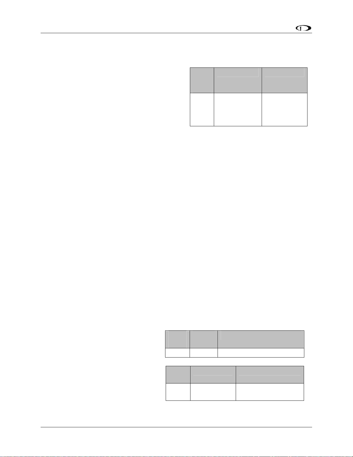
Instrument Installation
External EMS Warning Light
EMS DB37 Pin 29 can be wired and configured
as an external warning light, or alternatively, to
automatically control cabin light levels in sync
with the screen brightness of the Dynon
instruments.
To wire EMS DB37 Pin 29 as an external
warning light, you may connect any standard
LED or incandescent lamp (1.5 watts maximum),
used during EMS-related alarm conditions.
Ensure that the LED or lamp is designed for the voltage of your system. Mount it to your panel
according to its recommendations. Connect one of the lamp’s leads to your plane’s power.
Connect the other lead to pin 29 on the FlightDEK-D180 37-pin wiring harness. During an alarm
condition, this pin is connected to ground, causing current to flow through the lamp.
To configure EMS DB37 Pin 29 as an external warning light, enter the EMS menu by pressing
any button beneath an EMS main page. Press MORE > SETUP > GLOBAL. Press DOWN▼ to
select ALARM CONFIG and press SEL. LGT BHVR: ACK SOLID configures the external
alarm light to remain on (solid) when the alarm condition is acknowledged. LGT BHVR: ACK
CLEAR configures the external alarm light to go off when the alarm condition is acknowledged.
Verify correct operation of the external EMS warning by using the test function in the GLOBAL
menu. Enter the EMS menu by pressing any button beneath an EMS main page. Press MORE >
SETUP > GLOBAL. Press DOWN▼ to select ALARM CONFIG and press SEL. Select TEST
ALARM LIGHT and follow the instructions to test external light functionality.
EMS
DB37
Pin
29 Yellow/Green
Color Function
External
warning light
/ Dimmer
control
Dimmer mode function is generally used only by Original Equipment Manufacturers (OEMs). In
dimmer mode, the output of EMS DB37 Pin 29 is a Pulse Width Modulation (PWM) signal
proportional to the screen brightness setting of the Dynon instruments. To configure EMS DB37
Pin 29 for dimmer mode, enter the EMS menu by pressing any button beneath an EMS main
page. Press MORE > SETUP > GLOBAL. Press DOWN▼ to select ALARM CONFIG and
select LGT BHVR: DIM OUTPT.
Audio Alert Outputs
The FlightDEK-D180 has two audio
alarm outputs: one for sounding EMSrelated alarms, and one for sounding
AOA and altitude alarms sourced from
the EFIS. If you plan to use both alarm
outputs, connect these outputs (whose
pin numbers are shown in the tables at
right) together and then to the outside
terminal of a 10 kΩ variable resistor (not
included) as shown below. If you only
plan to use one of the audio alarm
DB25
Pin
18 Green EFIS Audio Alert Output
DB37
Pin
31 White/Orange
Color Function
Color Function
EMS Audio Alert
Output
4-10 FlightDEK-D180 Installation Guide
Page 49
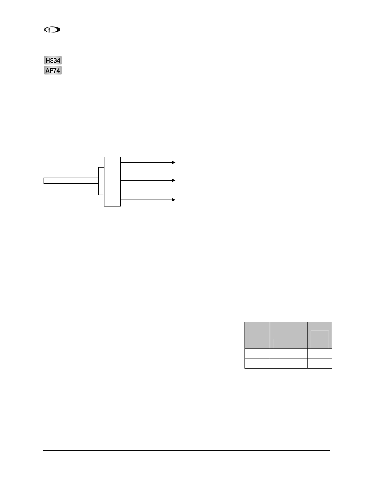
Instrument Installation
outputs, connect only its wire to the variable resistor.
If you have purchased and installed an HS34 and/or an AP74, we recommend that you
only connect the HS34 audio output or AP74 audio output (but not both) to your audio
panel. The HS34 or AP74 audio output provides voice and tone outputs for both EMSand EFIS-related alerts. When the HS34 or AP74 audio output is connected, it is not
necessary to connect the audio outputs of other Dynon Avionics devices. Connecting the
HS34 audio output and the AP74 audio output in parallel will result in distorted audio.
Refer to the HS34 Wiring section on page 9-10 for more information.
Ensure that audio outputs are connected similar to the following diagram. The 10 kΩ variable
resistor can be obtained from Radio Shack (P/N 271-1715) or other electronics suppliers.
Outside terminal
To FlightDEK-D180
Audio Alert(s) Out
Center terminal
To intercom/audio
panel auxiliary input.
Outside term
inal
To ground
To set the volume of the AOA and engine alarms, you will need your FlightDEK-D180 powered
on and the alarm output wired as described above. Enter the EFIS menu by pressing any button
(except the leftmost or rightmost) beneath an EFIS page. Press SETUP > AOAALM. In that
menu, press the TEST button. While the button is held down, the AOA alarm will sound. Adjust
the variable resistor until the volume in the intercom or audio panel is at an acceptable level.
Verify that this volume is acceptable for EMS alarms, which have a different tone. Enter the
EMS menu by pressing any button beneath an EMS main page. Press MORE > SETUP >
GLOBAL. Press DOWN▼ to select ALARM CONFIG and press SEL. Scroll down to select
TEST ALARM AUDIO. Press and hold SEL► to generate a tone on the audio output. Adjust
the variable resistor until the volume in the intercom or audio panel is at an acceptable level.
Dynon Smart Avionics Bus (DSAB) Wiring
The Dynon Smart Avionics Bus is the only way Dynon
products can communicate with one another, providing features
such as data sharing and alarm notification. DSAB is a multidrop bus, meaning several devices can be connected to the same
2 wires. If you have an EMS and EFIS product connected via
their serial ports through a null modem, you should disconnect
this legacy interface.
EFIS
DB25
pin#
Function
Wire
color
4 DSAB-A Green
5 DSAB-B Blue
You must connect the DSAB A connection (pin 4) on the EFIS DB25 female harness to the
DSAB A connection for the next device in the chain. Do likewise for the DSAB B connection
(pin 5). Some products – like the EFIS series and the HS34 – have only one pair of DSAB
connections on the back connector; other products – like the EMS series – have two pairs, for
wiring convenience. The FlightDEK-D180’s EMS connector does not have any active DSAB
lines on its 37-pin connector. If you have 3 or more devices in your system, and one of them is
FlightDEK-D180 Installation Guide 4-11
Page 50
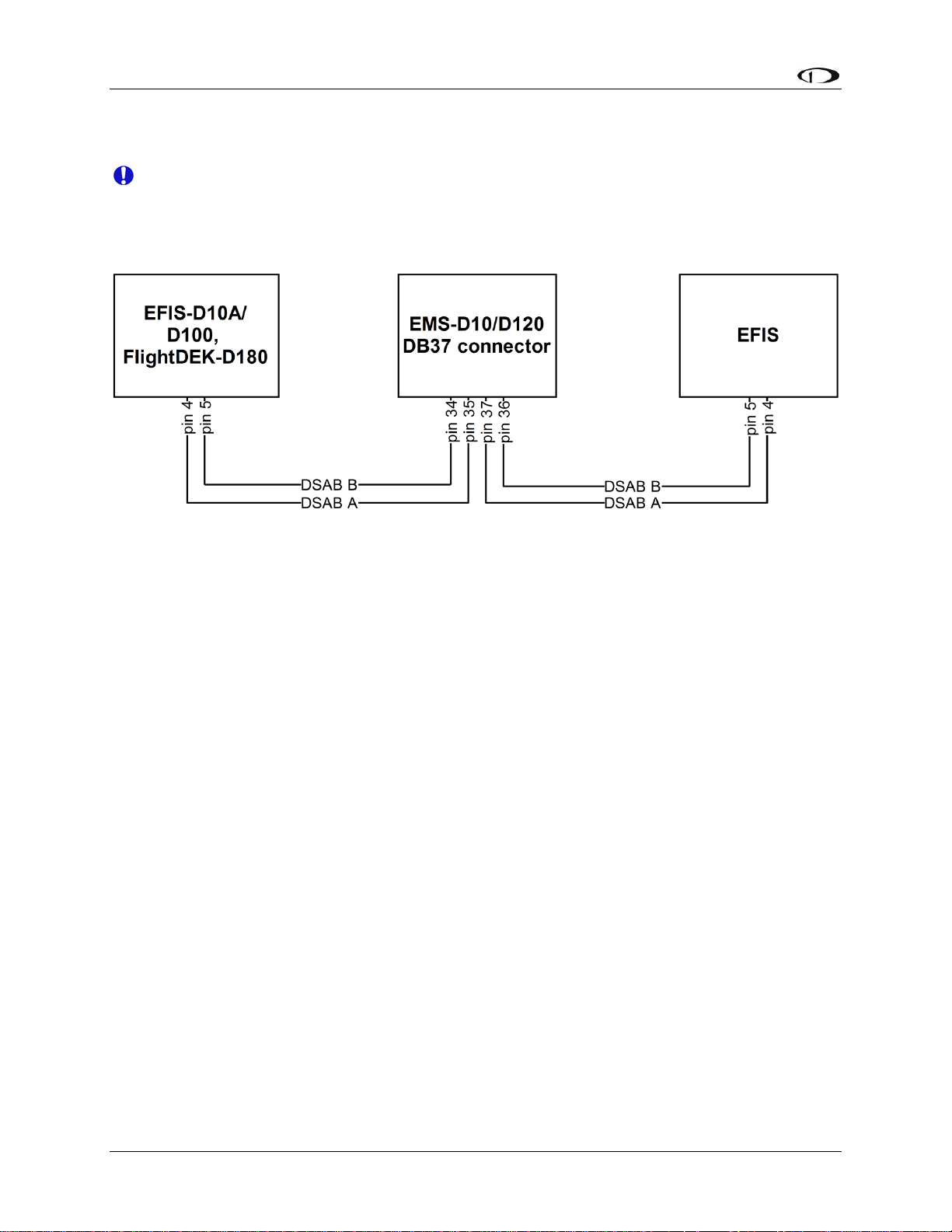
Instrument Installation
an EMS-series product, we recommend that you locate it in the middle of your wiring scheme as
shown below. This eliminates the need to splice two wires together.
Wherever possible, ensure that the two DSAB wires (DSAB A and B) are run as a
twisted pair. This minimizes the system’s susceptibility to electrical noise.
Refer to the DSAB Configuration chapter on page 7-1 for detailed instructions on configuring
your DSAB network.
4-12 FlightDEK-D180 Installation Guide
Page 51
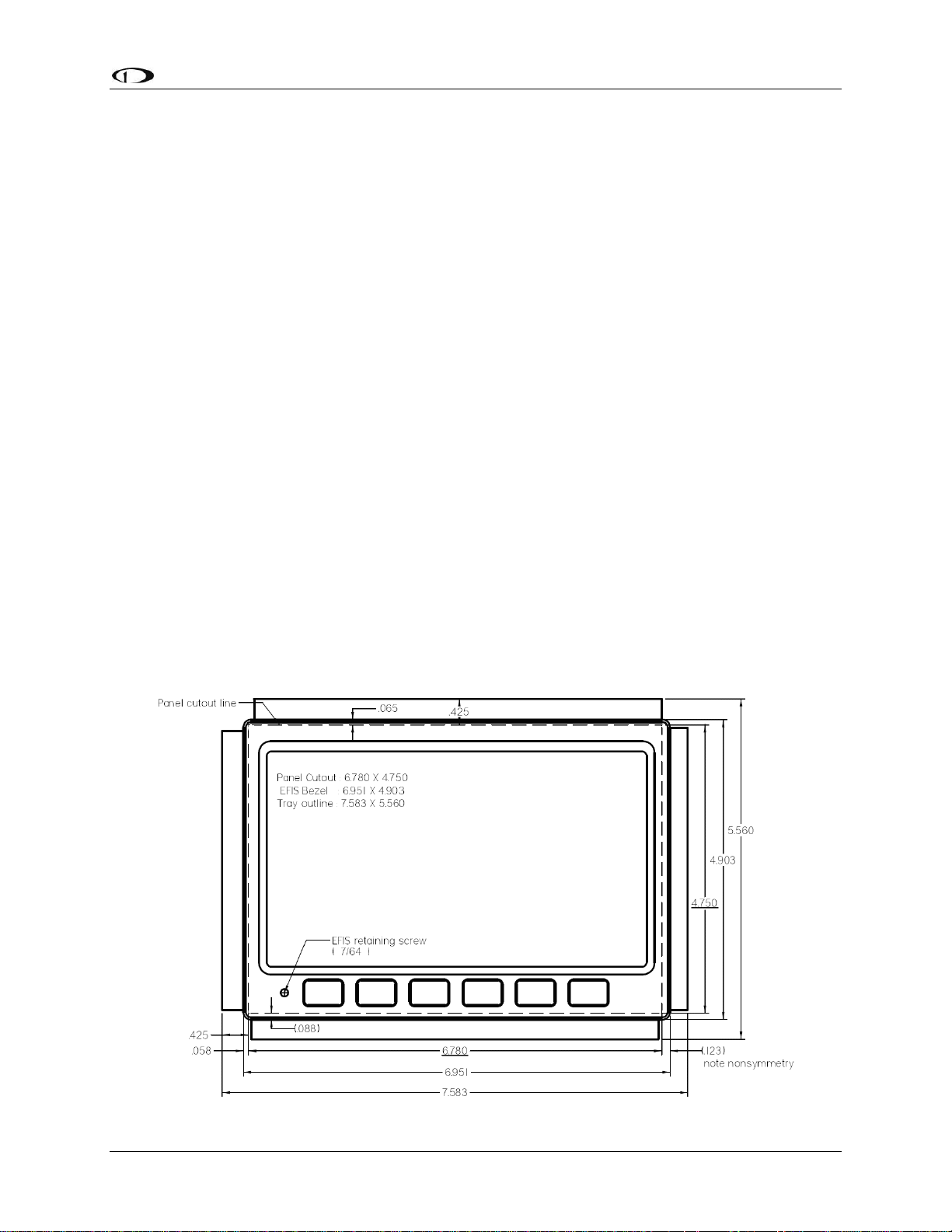
Instrument Installation
Panel Location and Mounting
The diagram below shows the outside dimensions of the front bezel of the FlightDEK-D180.
Note that the instrument and tray extend about 4.5” behind the panel, and the supplied harness
extends three inches more. Use the dimensions (in inches) found on the diagram to plan for the
space required by the instrument. Take the following considerations into account when selecting
a mounting location for the FlightDEK-D180.
Avoid placing the instrument near heater vents or any source of extremely hot or cold air. Keep
in mind that the air surrounding the FlightDEK-D180 during operation may be no warmer than
50 C. Plan a panel location that allows convenient viewing of the instrument with no
obstruction. When flying straight and level, the panel angle from vertical may not be greater than
+/- 30 degrees. The unit must also be parallel to the roll axis of the aircraft (although not
necessarily located along it), and have no significant roll angle in the panel. The firmware
supports an adjustment for panel tilt, but not for mounting errors in yaw or roll. Correct attitude
performance depends on mounting the FlightDEK-D180 square with the direction of flight.
To mount the FlightDEK-D180, you must make a rectangular cutout in your panel. Ensure that
the dimensions of the cutout are: 6.780” wide and 4.750” tall. Place the D100-series mounting
tray behind the cutout. Secure it to your panel in whatever way you desire. Riveting it to the
panel is ideal, but drilling holes for mounting screws and nuts will work as well. You may cut off
2 horizontal or vertical tabs from the mounting tray to minimize the space taken up behind the
panel. Upon securing the mounting rack to the back of your panel, slide the FlightDEK-D180
into it. Use the included 7/64” Allen wrench to secure the mounting screw (at the bottom left of
the front bezel) into mounting rack. At your discretion, you can also screw a #6-32 screw into the
back of the mounting rack on the opposite side. This screw should penetrate into the instrument
no further than ¼”.
FlightDEK-D180 Installation Guide 4-13
Page 52
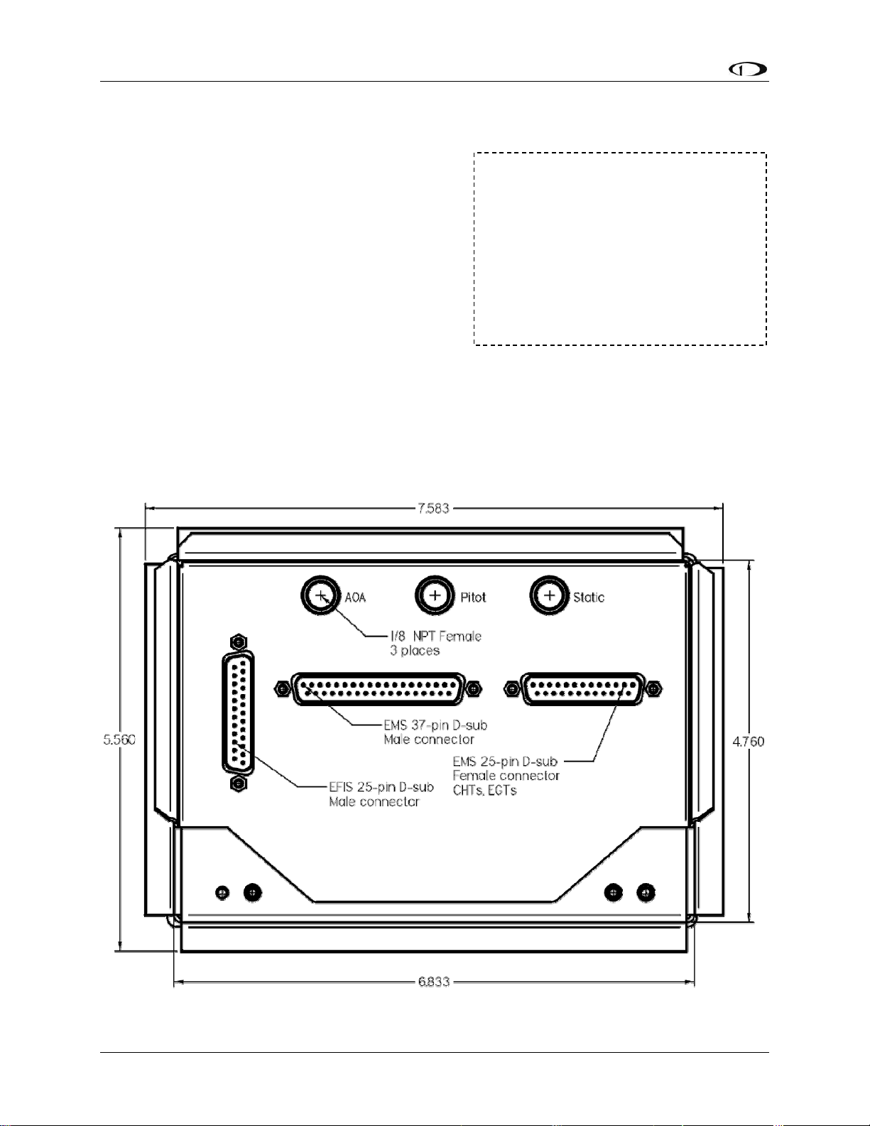
Instrument Installation
Connecting Static & Pitot Lines
The AOA, pitot, and static ports on the back of the
FlightDEK-D180 are equipped with 1/8” NPT
Female fittings. To attach your pitot and static lines
to the back of the FlightDEK-D180, you must use
standard 1/8” NPT Male fittings at the end of each
of the lines.
To install, simply connect your static and pitot
sources to the FlightDEK-D180, T’ing off of
existing lines if performing a retrofit. View the
following back view diagram the placement of your
pressure lines.
Use a wrench to secure the mating pressure line fittings to the corresponding locations on the
back of the FlightDEK-D180. Do not over-tighten.
If you purchased Dynon’s AOA pitot tube, note that it has pitot and AOA ports on it, but not
static. You will need to provide your own source of static pressure for the FlightDEK-D180 and
any other instrument in your panel which requires it.
The FlightDEK-D180’s attitude
calculation requires either airspeed
(from pitot and static) or GPS data.
To ensure proper operation, at least
one of these data sources must be
available. We recommend the
FlightDEK-D180 be connected to
pitot and static systems in all
installations.
4-14 FlightDEK-D180 Installation Guide
Page 53

5. EFIS CALIBRATION AND CONFIGURATION
During manufacture, your FlightDEK-D180 underwent a comprehensive calibration,
verification, and burn-in routine that minimizes setup time and ensures that your EFIS meets
Dynon’s stringent performance specifications. To account for your individual preferences and
your aircraft’s particular setup, there are a few simple calibration and configuration steps that
you must complete before using your FlightDEK-D180. This section takes you through these
steps to make sure that you have properly installed and configured your FlightDEK-D180.
CAUTION: It is your responsibility to fly your plane safely while performing any
configuration or calibration in flight. The best scenario would include a second person to
perform any necessary steps on the unit.
Ensuring Proper Installation
Turn your unit on by energizing the aircraft power to which it is connected. Ensure that the
screen is bright and readable and that all instrument displays appear. If a desired display item is
not present, refer to the User’s Guide to use the CLUTTR feature to display the missing item.
Setting Zero Pitch (In flight)
For the purposes of this setting, level is defined as the attitude at which the aircraft’s
longitudinal axis is parallel to the ground. For most aircraft, the attitude the aircraft
assumes at normal cruise speeds will be acceptable. Additionally, this feature should not
be used to “zero out” pitch when the aircraft is at an attitude other than level. Do not
think of this adjustment as you would the parallax adjustment on a normal attitude
indicator. Instead, think of it as a calibration step which is not changed often.
With your aircraft flying straight and level, enter the EFIS > SETUP > PITCH menu. Press INC
or DEC until the horizon line intersects the center of the crosshairs. It is important that this be
done while the aircraft is level to ensure proper pitch and roll display throughout all maneuvers.
Compass Heading Calibration
This section guides you through the calibration and configuration of your magnetic heading
indication. Prior to calibrating your EDC-D10A, you must configure the local magnetic
inclination and magnetic intensity as described in the sections below.
In a DSAB network, the Bus Master’s heading is used as the only heading source for all
connected instruments. However, in the event of a DSAB failure, EFIS instruments revert
to their local heading source. In a system already using a shared heading, you may still
configure and calibrate the local heading source. As soon as you bring up any of the
magnetic calibration menus (MAGINC, MAGCAL, MAGADJ, MAGINT), the heading
and DG displays switch to display the locally-derived heading indication. The display
stays on that source until exiting the magnetic configuration menu. If you do not have an
EDC-D10A connected, REMOTE COMPASS NOT DETECTED is displayed when in
any of these menus.
FlightDEK-D180 Installation Guide 5-1
Page 54

EFIS Calibration and Configuration
SETTING MAGNETIC INCLINATION ANGLE AND INTENSITY (REQUIRED)
To calibrate your FlightDEK-D180 heading, you must input your location’s current
magnetic inclination angle and intensity. Before doing this, you must obtain these two
values for the geographic location where you will be performing the calibration. Note that
this procedure only needs to be done once, prior to magnetic calibration. Moving the
aircraft to another location does not require repeating this procedure.
Obtaining Magnetic Inclination and Intensity
1. Browse to web page: www.dynonavionics.com/docs/maginfo.html. (Looking up this
information does not have to be done on a computer at the plane, with live Internet
access.)
2. The Dynon Avionics “Magnetic Inclination and Intensity” web page is updated as
needed; it contains a link to a NOAA web pages and instructions for easily finding your
local magnetic inclination and intensity by inputting your ZIP code (in the US) or your
latitude and longitude and inputting the resulting data into your Dynon EFIS.
3. Follow the instructions listed on the web page, especially clicking the “Compute
Magnetic Field Values” button at the bottom of the linked page – the values required by
your Dynon EFIS will be displayed only after clicking that button. If you are near the
equator or in the southern hemisphere, note that the inclination may be negative number.
Entering inclination and intensity into the FlightDEK-D180
1. Enter the inclination setup menu by pressing any button beneath an EFIS page (except the
far left or far right hotkeys), then MORE > SETUP > MORE > MORE > MAGINC
2. Press INC or DEC to increment or decrement the displayed inclination angle. Press and
hold to change values more rapidly.
3. When the display shows the magnetic inclination angle for your location, press BACK to
leave the menu.
4. Enter the magnetic intensity setup menu by pressing any button beneath an EFIS page
(except the far left or far right hotkeys), then MORE > SETUP > MORE > MORE >
MAGINT
5. Press SEL► to change the digit being incremented or decremented. Press INC or DEC to
increment or decrement the selected digit. Press and hold to change values more rapidly.
6. When the display shows the magnetic intensity for your location, press BACK to leave
the menu.
5-2 FlightDEK-D180 Installation Guide
Page 55

EFIS Calibration and Configuration
EDC-D10A HEADING CALIBRATION (ON GROUND ONLY)
The procedure for in-plane calibration of the EDC-D10A involves pointing the aircraft in four
directions and taking data at each direction using the FlightDEK-D180. The FlightDEK-D180
will then perform some calculations to ensure an accurate calibration.
During magnetic calibration, do not turn the power off on the FlightDEK-D180. This will
cause any recorded compass calibration data to be lost; the calibration will need to be
restarted.
To perform the calibration, you will need the following:
1. FlightDEK-D180 and EDC-D10A installed in aircraft.
2. Magnetic inclination angle and intensity properly entered into the FlightDEK-D180 per
the section above.
3. An accurate method of aligning the aircraft with magnetic North, East, South, and West,
such as an airport’s compass rose.
Once you have the installation completed, have verified that your EDC-D10A communicates
with the FlightDEK-D180 (i.e., you see the heading tape displayed on the EFIS main page), and
have located a suitable place to perform the calibration, perform the following steps:
1. Turn on the FlightDEK-D180 and allow it to warm up for at least 15 minutes before
performing the calibration.
2. Align the aircraft pointing magnetic North as closely as possible.
3. On the FlightDEK-D180, enter the menu system by pressing any button beneath an EFIS
page (except the far left or far right hotkeys) and press MORE > SETUP > MORE >
MORE > MAGCAL. You should see a menu that reads NORTH, EAST, SOUTH, and
WEST. If you do not, then the EDC-D10A is not properly communicating with your
FlightDEK-D180.
4. Press the NORTH button; you will see the message, COLLECTING DATA FOR
NORTH along with a 15 second timer. Let the time run out before proceeding.
5. Align the aircraft pointing magnetic East as closely as possible.
6. Press the EAST button; you will see the message, COLLECTING DATA FOR EAST
along with a 15 second timer. Let the time run out before proceeding.
7. Align the aircraft pointing magnetic South as closely as possible.
8. Press the SOUTH button; you will see the message, COLLECTING DATA FOR
SOUTH along with a 15 second timer. Let the time run out before proceeding.
9. Align the aircraft pointing magnetic West as closely as possible.
10. Press the WEST button; you will see the message, COLLECTING DATA FOR WEST
along with a 15 second timer. Let the time run out before proceeding.
11. Press the END button. This will cause the FlightDEK-D180 to pause as it calculates. This
pause should last between 1-20 seconds. However, if the collected data is poor, this can
FlightDEK-D180 Installation Guide 5-3
Page 56

EFIS Calibration and Configuration
take as long as 5 minutes. A message will be displayed onscreen: CALCULATING
MAGNETIC CALIBRATION VALUES.
12. Wait for the message CALIBRATION COMPLETE before attempting to use the
FlightDEK-D180 or remove power. Press BACK to leave the menu.
This completes the EDC-D10A calibration process. The process can be repeated as often as
desired. The overall accuracy of the compass depends on the installation location (away from
any ferrous materials or current carrying wires or devices), the installation alignment (aligned
with the FlightDEK-D180 in pitch, roll, and yaw), and the calibration procedure (accurately
aligning the aircraft with North, East, West, and South and having the correct magnetic
inclination angle loaded into the FlightDEK-D180). If the compass performance is not adequate
for your usage, we suggest that you investigate each of these factors and try to optimize your
installation for each factor.
If the heading shown onscreen is off by a small, but constant amount, you can change a heading
offset in the FlightDEK-D180 which will correct this. Orient your plane in a known direction,
preferably on a compass rose at the airport. Navigate to the Heading Adjustment menu by
pressing MORE > SETUP > MORE > MORE > MAGADJ. Increment or decrement the value of
the heading offset until the FlightDEK-D180 heading corresponds to the direction in which your
plane is pointed.
Troubleshooting
During the calibration process you may receive one of the following errors. Next to each one is
the corrective action required.
Message Corrective Action
You have not entered the magnetic inclination
WARNING: MAGNETIC INCLINATION
NOT SET.
WARNING: MAGNETIC INTENSITY NOT
SET.
into the FlightDEK-D180 yet. Please see the
“Entering Magnetic Intensity and Inclination
Angle” section
You have not entered the magnetic inclination
into the FlightDEK-D180 yet. Please see the
“Entering Magnetic Intensity and Inclination
Angle” section
Configure Airspeed Color Thresholds
To configure the airspeed bar color thresholds for your unit enter the EFIS > SETUP > IASCLR
menu. This displays the Airpseed Color Threshold menu. In this menu, enter the values for five
airspeed constants (Vso, Vs1, Vfe, Vno, and Vne), each of which has its own button. Enter these
values in units of knots, mph, or km/h depending on what airspeed units you are currently using
(you may change the displayed airspeed units via EFIS > SETUP > UNITS > IAS).
Perform the following steps for each airspeed constant:
1. Press SEL► to select the digit you wish to increment or decrement.
2. Press DEC- or INC+ to decrement or increment the selected digit.
5-4 FlightDEK-D180 Installation Guide
Page 57

EFIS Calibration and Configuration
3. Press BACK to return to the previous menu.
You will not be able to see some of the colors until the aircraft has achieved airspeeds in
the range of each threshold.
FlightDEK-D180 Installation Guide 5-5
Page 58

Page 59

6. EMS CONFIGURATION
Once the engine sensors are
physically installed, you must
configure the FlightDEK-D180 to
recognize and correctly display all
engine parameters. To interact with
the FlightDEK-D180 menu system,
use the 6 buttons on the front panel.
The buttons are numbered one to
six, left to right. With the instrument
powered on and the EMS main page
displayed, press any button (except
the leftmost and rightmost buttons, reserved for hotkey screen switching) beneath the EMS main
page to bring up the menu. Press MORE to see the next menu, and then SETUP to enter the
setup menu. Pressing MORE will toggle through the various SETUP options. For the purposes of
installation, you will be dealing with the GLOBAL, SENSOR, FUEL, TRIM (if installed) and
FLAPS (if installed) options.
Full-Page Setup Menu Overview
When in full-page menus, follow these
tips to navigate through them:
Use the DOWN▼ and UP▲ buttons to
scroll up and down through menu items.
Use the SEL► button to enter a submenu
(the white area) as shown at right.
When in a submenu, press UP▲ and
DOWN▼ to scroll through the available
options.
If you have selected a value that can be
toggled between a small number of values (like ALARM status), the SEL► button will appear.
Press SEL► to toggle the value through its possible states. In the case of ALARM status,
pressing SEL► would cycle from OFF to SELF-CLEAR to LATCHING and back to OFF.
If you have selected a value that can be incremented and decremented (like the HI YEL/GRN
color boundary), the INC+ and DEC- buttons will appear. Press INC+ to increase the value and
DEC- to decrease it.
The FlightDEK-D180 comes with most displays defaulted to ON. If you have not installed a
given sensor or have reason to not display it, set the DISPLAY parameter to OFF.
The FlightDEK-D180 supports multiple types of sensors for some functions. For any input which
supports more than one type of sensor, you must select a “sensor type” in its configuration
section. This information is used by the FlightDEK-D180 to determine which sensor is installed
for a given function. The default sensor type, “1,” is the most common Dynon-supplied sensor
FlightDEK-D180 Installation Guide 6-1
Page 60

EMS Configuration
for each function. The various supported sensors and their types are described below, starting at
page 6-8.
Alarm and Color Threshold Configuration
In the various sensor setup menus, you will be configuring the alarms and color thresholds.
Below is an introduction to the principles used.
If you have configured EMS > GLOBAL > ENGINE TYPE to ROTAX, then the color thresholds
for the Tachometer and Oil Temperature are automatically set in accordance with manufacturer
specifications.
Alarms for any given sensor can have three different modes of operation. They are:
OFF – When the selected sensor enters the red portion of its analog gauge, no alarm will be
sounded. Use this mode if you have not installed the selected sensor or do not wish to be alerted
when its value is beyond the norm.
SELF-CLEAR – When an alarm
condition occurs for the selected
sensor, an alarm will be displayed
(and sounded, if the audio alert
connection to the intercom is
made). If the given parameter
enters normal values (i.e., comes
out of the red), the alarm will be
cancelled.
LATCHING – The alarm will
continue to be displayed, even if
the condition has returned to
normal values again.
AOA (appears only on EMS Contact 1 and EMS Contact 2) – When EMS Contact 1 or EMS
Contact 2 is activated, the AOA alarm in the EFIS section of the instrument is triggered; the
resulting alarm depends on how the EFIS AOA alarm is configured (EFIS TONE, EXT TONE,
or EXT VOICE).
All displayed analog bars have color thresholds which must be set. Navigate to each threshold to
increment or decrement it. Each number represents the value – in the units of the displayed
parameter. So, in the picture above, the top section of the oil pressure analog bar is set to 99 PSI;
the threshold between the upper portion of red and the upper portion of yellow is set to 95 PSI;
and so on. If an alarm for a given sensor is enabled (either SELF-CLEAR or LATCHING), the
alarm will trigger at the red/yellow boundaries.
Some sensors have color thresholds on the high and low side; others have thresholds on only one
side or the other. This depends on the individual value being displayed and whether its being too
high or too low is noteworthy. Whenever a value is in normal operating conditions (green on the
analog bar), its displayed numeric value will be white. When any value enters a yellow or red
zone on its analog bar, the respective numeric value will change colors accordingly.
6-2 FlightDEK-D180 Installation Guide
Page 61

EMS Configuration
When you modify one value, it will not “push” another value up or down. So, in the example
above, you would not be able to increment the HI YEL/GRN parameter beyond 95 until you
increased the HI RED/YEL parameter. Likewise, you would not be able decrement the HI
RED/YEL value below 90 until you decrease the HI YEL/GRN parameter.
To disable alarms before engine start, enter the EMS > SETUP > GLOBAL > ALARM CONFIG
menu. Set PWR ON ALARMS to OFF. With this parameter set to “OFF”, all alarms are
suppressed whenever ALL of the following conditions exist:
RPM less than 400
Oil pressure less than 20 PSI
First five minutes after master instrument power applied
All alarms are initialized when any of the above conditions are exceeded.
Global Parameters Setup
When in the SETUP menu, press GLOBAL to
bring up the full-screen menu seen at right. D
installation, you only need to deal with the items
under the INSTALL SETUP section. During
install, you may want to change the units to the
setting that is convenient for you. If you are not
the intended pilot using the instrument, he or she
may easily change units to whatever they desir
without affecting calibration or configu
Refer to the FlightDEK-D180 Pilot’s User Gu
for more detailed information about the PILOT SETUP and SCREEN SETUP sections of the
GLOBAL menu.
uring
e
ration.
ide
Press DOWN▼ until you have selected the item, # OF CHT. Press SEL► until the number
shown reflects the number of cylinder head temperature sensors installed on the engine. For
Rotax 9-series engines, select 2 to indicate the fact that the EMS will
be monitoring the left and right pairs of cylinders.
Press DOWN▼ to select the item, # OF EGT. Press SEL► until the
number shown reflects the number of exhaust gas temperature sensors
installed on the engine.
Press DOWN▼ to select the item, CYL DISP. Press SEL► to toggle
between SPLIT and COMBD. The split display presents CHTs and
EGTs in separate locations as horizontal bars, and is available for 2 a
4 cylinder displays. The combined display presents CHTs and EGT
nd
s in
Split display
the same location with EGTs as horizontal bars, and CHTs as tics on
the bars.
Press DOWN▼ to select the item, # OF FUEL TANKS. Press SEL►
until the number shown reflects the number of fuel tanks included on
the aircraft.
Combined display
FlightDEK-D180 Installation Guide 6-3
Page 62

EMS Configuration
If you need to adjust the Hobbs time on the FlightDEK-D180 to match that of your engine, press
DOWN▼ to select the item, SET HOBBS TIME. Press SEL► to enter the Hobbs time setting
submenu. Press SEL► to select the desired digit and then DOWN▼ or UP▲ to change the
value. When you are finished, press BACK.
If you need to adjust the tachometer time on the FlightDEK-D180 to match that of your engine,
press DOWN▼ to select the item, SET TACH TIME. Press SEL► to enter the tachometer time
setting submenu. Press SEL► to select the desired digit and then DOWN▼ or UP▲ to change
the value. When you are finished, press BACK.
Engine Type Configuration
Within the GLOBAL menu, press DOWN▼ until you have selected ENGINE TYPE. Press
SEL► to toggle between LY/CON, ROTAX, and OTHER.
ENGINE TYPE: LY/CON
Setting ENGINE TYPE to LY/CON enables a percent power display for normally aspirated/nonturbocharged Lycoming or Continental engines. Press DOWN▼ to select HP RATING and use
the INC+ and DEC- buttons to set the value to the actual horsepower rating for your engine.
Given the horsepower rating, an OAT, fuel flow, and altitude (from a connected EFIS-based
product or GPS), the FlightDEK-D180 will calculate percent power and lean-of-peak/rich-ofpeak status, displaying both next to the Manifold Pressure gauge.
For percent power status to be calculated as accurately as possible, TACHOMETER
(RPM) HI RED/YEL should be set to the RPM value specified by the Engine
Manufacturer. (This is commonly referred to as “Redline”).
If you do not have a fuel flow sender, the FlightDEK-D180 will still display a percent power
reading based on rich-of-peak calculations only. During lean-of-peak operation, percent power is
displayed but is incorrect. While you are in LEAN mode, percent power is not displayed.
ENGINE TYPE: ROTAX
Setting ENGINE TYPE: to ROTAX pre-configures some settings for a Rotax 912 engine. Rotax
914 engines must be manually configured using ENGINE TYPE: OTHER. A percent power
reading will not be displayed, but the FlightDEK-D180 will automatically configure and
dynamically change the oil temperature and tachometer scales and alert thresholds in accordance
with Rotax’s recommended ranges, described in detail below.
RPM / TACHOMETER for Rotax 912:
When OIL TEMP < 120ºF, the TACHOMETER displays these ranges:
0-1400 and 4000-6000 RPM in RED
1400-1800 and 2500-4000 RPM in YELLOW
1800-2500 RPM in GREEN
When OIL TEMP > 120ºF, the TACHOMETER displays different ranges:
0-1400 and 5800-6000 RPM in RED
6-4 FlightDEK-D180 Installation Guide
Page 63

EMS Configuration
1400-1800 and 5500-5800 RPM in YELLOW
1800-5500 RPM in GREEN
At 0 RPM, the LOW RPM ALARM is inhibited. When RPM advances above 0, the LOW RPM
ALARM is inhibited for 10 seconds. The HIGH RPM ALARM is always active.
OIL TEMP Gauge for Rotax 912:
When OIL TEMP < 190ºF, the OIL TEMP gauge displays these ranges:
100-120 and 230-266ºF in YELLOW
120-190ºF in GREEN if OIL TEMP has been above 190ºF “more recently” than OIL TEMP
was below 120ºF; otherwise 120-190ºF is displayed in BLACK OUTLINED IN WHITE
190-230ºF in GREEN
266-280ºF in RED.
When OIL TEMP is > 190ºF, the OIL TEMP gauge will display different ranges:
100-120 and 230-266ºF in YELLOW
120-230ºF in GREEN
266-280ºF in RED
ENGINE TYPE: OTHER
For all other engine types, select OTHER. Currently, the FlightDEK-D180 calculates percent
power only for normally-aspirated Lycoming or Continental engines. Dynon Avionics will
consider adding more engine types to our percent power calculations. If your engine is not
currently supported and you would like to see it considered for possible inclusion, please send
your engine’s power chart to: betatest@dynonavionics.com.
Fuel Level Calibration
Prior to calibrating your fuel tanks, ensure that you have made the correct fuel level sensor type
selection as described on page 6-13.
Enter the EMS m
below an EMS main page and pressing MORE >
SETUP > MORE > FUEL. You are presented
with the screen shown below. The menu reflects
the number of fuel tanks selected in the Global
Parameters Setup, as described on page 6-3. If y
do not see the correct number of tanks here, go
back to the GLOBAL section of the SETUP menu
and set the correct number of tanks.
enu by pressing any button
ou
Begin with empty tanks and be ready to fill them to capacity with an accurate way of adding fuel
in defined increments (i.e. a standard gas pump gauge). Orient your plane into level flight
attitude, and repeat the following steps for each tank you wish to calibrate.
FlightDEK-D180 Installation Guide 6-5
Page 64
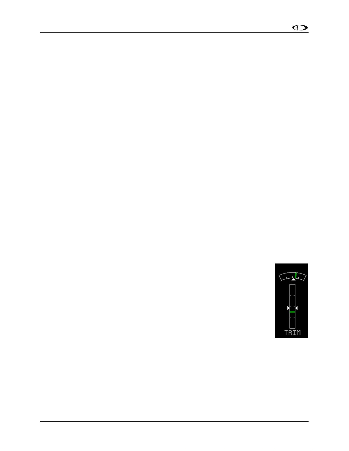
EMS Configuration
Use the DOWN▼ or UP▲ buttons to select the tank that you wish to calibrate, and press
SEL►.
Enter the approximate number of gallons or liters the tank can hold. It is not necessary to be
precise. This number is only used to determine reasonable fuel addition increments in the next
steps. Press NEXT. Once you have confirmed that the tank you are calibrating is empty, press
START. Follow the on-screen instructions until the completion of your fuel calibration.
At the completion of your fuel level calibration, the FlightDEK-D180 will present you with a
table of values in the format “[pour #]: [mV] [gallons]”. Ensure that the mV values (just after the
colon) change throughout the range of pours. Also, it is highly advised that you create a backup
of your FlightDEK-D180 via the Dynon Product Support Program as soon as possible. This will
ensure that the fuel calibration data is backed up, reducing the likelihood that you’ll need to
repeat the process. Refer to the Dynon Product Support Program help file for more details on this
process. Keep the firmware backup file in a place on your computer where you can easily find it
again.
In addition to calibrating your fuel tanks, you may make a few settings that will enhance the
functionality of the fuel computer. First, entering the FULL VALUE menu will allow you to
configure the total amount of fuel available between all your tanks. This is used to calculate fuel
remaining and other values, as well as allowing you to reset the fuel computer to a full fuel value
with one button press. Likewise, the PRESET VALUE menu allows you configure a preset total
fuel value – distinct from the full value – which you can reset the fuel computer to. Finally, the
ADD THRESHOLD menu allows you to configure the fuel computer to automatically detect the
addition of fuel when the EMS was off. The fuel computer will check the fuel level senders at
boot and prompt the pilot to add fuel when it measures an increase beyond the set threshold. The
threshold is set as a percentage of the full measurable amount of fuel.
Trim Calibration
Prior to calibrating your trim sensors, ensure that you have connected them as
described on page 3-16 and made the correct trim type selection for the desired GP
inputs as described on page 6-17.
Enter the EMS menu by pressing any button below an EMS main page and
pressing MORE > SETUP > MORE > TRIM. The TRIM CALIBRATION menu
shows AILERON, ELEVATOR, and RUDDER, followed by the GP input that
each is configured as (or NONE, if no GP input is configured for a given axis).
Ensure that this list corresponds to the physical connections made during the setup
described in the Trim and Flaps Position Potentiometers section on page 3-16.
During the calibration process, the onscreen instructions will direct you to put the trim into
various positions, pressing NEXT after each change. The calibration process allows you to set a
takeoff trim position; this position is displayed as a green line on the trim scale info item. During
the calibration process, ensure that the number shown in the VALUE field changes as you adjust
the trim. If the number does not change, the trim sensor may be incorrectly wired to the
FlightDEK-D180, or incorrectly configured in the GP input selection under the SENSOR menu.
At any point in the process, you may press CANCEL to end the calibration without overwriting
the previous calibration results.
6-6 FlightDEK-D180 Installation Guide
Page 65

EMS Configuration
Once you are ready to calibrate, select the desired trim that you would like to calibrate, and press
SEL► to enter its calibration menu. Press the RANGE button to begin calibrating the range of
the trim. Follow the onscreen instructions, controlling trim to the required position before
pressing NEXT. Repeat the process for the opposite position. The process will then prompt you
to put the trim into takeoff position. If you do not require a takeoff indication on the given axis’
trim display, you may press NONE. When you have completed the calibration, press the DONE
button.
Press the TAKOFF button to calibrate the takeoff position indicator. When calibrated, a green
line is displayed on the trim scales, indicating takeoff position.
View the trim display on the EMS Main or Aux page (depending on where you configured it to
display) to make sure that it works as expected. You may repeat this calibration process as many
times as you wish.
Flaps Calibration
Prior to calibrating your flaps sensor, ensure that you have connected it as
described on page 3-16 and selected FLAP POS for the desired GP input FUNCT
parameter as described on page 6-17.
Enter the EMS menu by pressing any button below an EMS main page and
pressing MORE > SETUP > MORE > FLAPS. The FLAP CALIBRATION menu
just shows FLAPS, followed by the GP input that each is configured as (or NONE,
if no GP input is configured for a given axis). Ensure that this list corresponds to
the physical connections made during the setup described in the Trim and Flaps
Position Potentiometers section. Press SEL► to enter the flaps calibration menu.
During the calibration process, ensure that the number shown in the VALUE field changes as
you adjust the flaps. If the number does not change, the flaps sensor may be incorrectly wired to
the FlightDEK-D180, or incorrectly configured in the GP input selection under the SENSOR
menu. At any point in the process, you may press CANCEL to end the calibration without
overwriting the previous calibration results.
You must calibrate for at least 2 positions, and may calibrate for as many as 5. The calibration
process first requires you to put the flaps in the 0° extended position. When you have done this,
press NEXT. Next, you will calibrate for the second position. Press INC+ or DEC- to set the
angle that you would like displayed for the second position. If you only wish to have 2 positions
displayed, press DONE. Otherwise, press NEXT to repeat the process for the third position.
When you have completed the calibration, press DONE. View the flaps display on the EMS
Main or Aux page (depending on where you configured it to display) to make sure that it works
as expected. You may repeat this calibration process as many times as you wish.
FlightDEK-D180 Installation Guide 6-7
Page 66
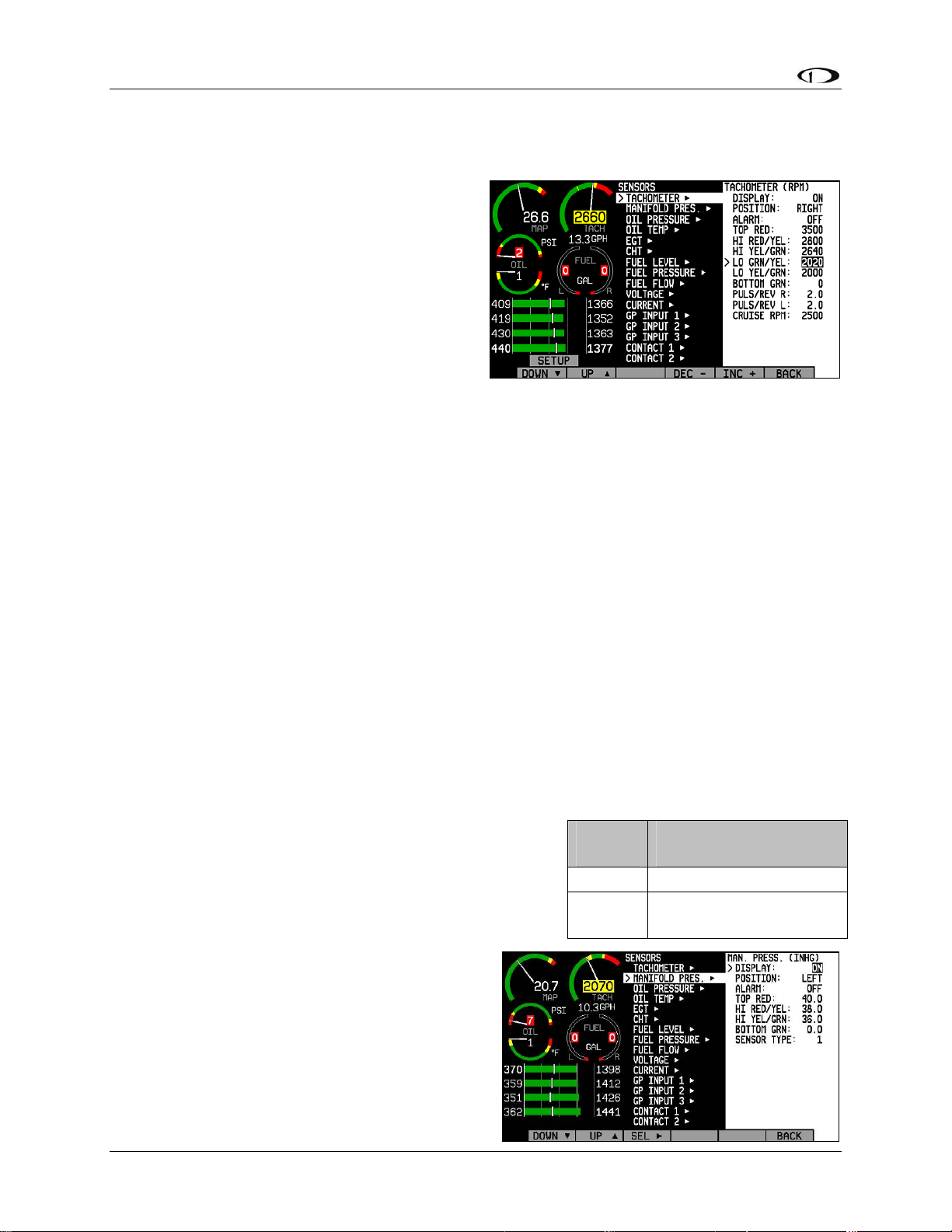
EMS Configuration
Tachometer
If you have connected a tachometer source to
either the RPM Left or Right inputs, set the
DISPLAY parameter to ON, otherwise, set it to
OFF. Next, select whether the tachometer is to
the left or right of the manifold pressure display.
Simply select POSITION and press SEL► to
toggle between LEFT and RIGHT.
Select the alarm mode and the analog bar
thresholds as described in Alarm and Color
Threshold Configuration on page 6-2. Unlike
most sensor displays, the tachometer supports a yellow band in the middle of the green band to
accommodate engines which have a range of unsafe RPMs in the middle of the safe range. If you
do not require this extra yellow band, simply set the LO GRN/YEL and LO YEL/GRN
parameters to the same value.
Increment or decrement the PULS/REV R and L values to correspond to the number of pulses
put out by your tachometer source for each engine revolution. You may select the pulses/rev for
both the left and right tachometer inputs independently. If they are both p-lead inputs, these will
likely be the same number. However, if you have connected two different types of tachometer
sources, you will likely have to input different values into these fields. If you are using a p-lead
connection, the PULS/REV value will typically be set to ½ or ¼ of the number of cylinders in
the engine. If you find that the onscreen tachometer reads double or half what you expect, adjust
the PULS/REV value until you observe the expected value. If you do not have anything hooked
to one of the tachometer inputs, the PULS/REV setting for this input can be set to any value. The
FlightDEK-D180 will automatically ignore this unused input.
Next, enter your normal cruise RPM. This is used when computing Tach Time on the TIMES
page. See the FlightDEK-D180 Pilot’s User Guide for more information.
Manifold Pressure
If the manifold pressure transducer has been installed, set
the DISPLAY parameter to ON, otherwise, set it to OFF.
Change the SENSOR TYPE to the correct number using
the sensor type table. Select the alarm mode and the
analog bar thresholds as described in Alarm and Color
Threshold Configuration on page 6-2. Next, select
whether the tachometer is to the left or right of the
manifold pressure display. Simply select
POSITION and press SEL► to toggle between
LEFT and RIGHT. You will also see a similar
selection in the manifold pressure setup menu.
Select the sensor type using the sensor type table
below. If you select the GRT manifold pressure
6-8 FlightDEK-D180 Installation Guide
Sensor
Type
1 Dynon P/N 100434-000
2
Manifold Pressure
Sensor
GRT MAP-01 or MAP-
02
Page 67
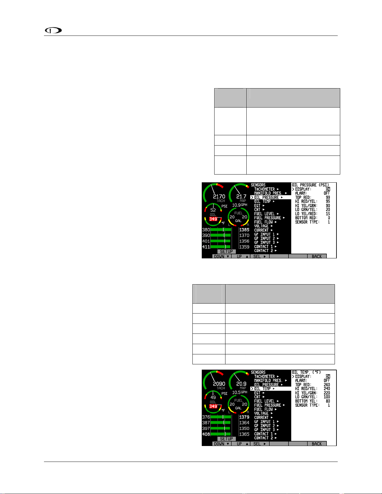
EMS Configuration
sensor, you will be presented with the values AuxSF and AuxOff. You must enter these values
according to the ones printed on your manifold pressure sensor, provided by GRT.
Oil Pressure
Select the alarm mode and the analog bar thresholds
as described in Alarm and Color Threshold
Configuration on page 6-2. If the oil pressure
transducer has been installed, set the DISPLAY
parameter to ON, otherwise, set it to OFF. Change
the SENSOR TYPE to the correct number using the
sensor type table.
Sensor
Type
1
2 GRT HPS-01
3 Jabiru pre-installed
4
Oil Pressure Sensor
Dynon P/N 100411-002 or
Rotax 912 pre-installed
(prior to mid-2008)
Rotax P/N 956413 (mid-
2008 and later
Oil Temperature
Select the alarm mode and the analog bar
thresholds as described in Alarm and Color
Threshold Configuration on page 6-2. If the
oil tem
the DISPLAY parameter to ON, otherwise,
set it to OFF. Change the SENSOR TYPE to
the correct number using the sensor type
table.
perature sensor has been installed, set
Sensor
Type
1 Dynon P/N 100409-001
2 Dynon P/N 100409-000
3 GRT FT-LC-01
4 Rotax pre-installed
5 Jabiru pre-installed
6 Chevrolet LS7 pre-installed
Oil Temp Sensor
FlightDEK-D180 Installation Guide 6-9
Page 68
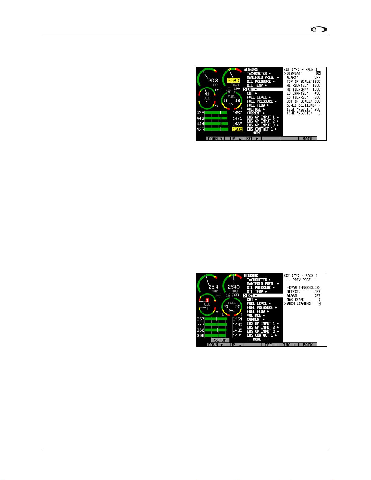
EMS Configuration
Exhaust Gas Temperature (EGT)
Select the alarm mode and the analog bar
thresholds as described in Alarm and Color
Threshold C
more EGT thermocouples have been installed, set
the DISPLAY parameter to ON; if no EGT
thermocouples are installed, set it to OFF. There
is no need to set a sensor type; any K-type
thermocouple will work.
In addition to the configuration of the color
thresholds, you can configure the top and bottom of the EGT/CHT analog scales independently.
This allows you to show a narrower region of interest on the analog gauges to ensure easy
detection of minor differences between cylinders. The TOP OF SCALE parameter defines the
highest temperature displayed on the EGT analog gauge; The BOT OF SCALE parameter
defines the lowest temperature displayed on the EGT analog gauge; the SCALE SECTIONS
defines the number of sections into which the entire scale range is divided. Set the TOP OF
SCALE, BOT OF SCALE, and SCALE SECTIONS to suit your needs.
onfiguration on page 6-2. If one or
For all SPLIT cylinder displays (2 and 4 cylinders only), you can set the SCALE SECTIONS for
EGT and CHT independent of each other. For COMBD displays, EGT and CHT SCALE
SECTIONS are tied together as the two sets of measurements are displayed on the same graph.
All 1/3 EMS displays show EGTs and CHTs in the combined view. If you have set the
EGT/CHT displays to be split on 2/3 EMS pages, swapping to a 1/3 EMS will cause the EGT
SCALE SECTIONS value to take precedence over the CHT SCALE SECTIONS.
SPAN ALARMS
You may configure alarms based on the overall
temperature span between the hottest and coolest
cylinders’ EGTs. The span alarm configuration is
located on the second page; press DOWN▼ from
the bottom of page 1. First, press SEL► to toggle
the DETECT setting to ON. Like other alarms,
you can cycle ALARM through SELF-CLEAR,
LATCHING, and OFF. See Alarm and Color
Threshold C
def
initions of those functions. Next, configure the MAX SPAN (the maximum temperature
difference between hottest and coolest cylinders, in the units shown at the top of the menu)
during non-leaning conditions. Next, configure the maximum span while leaning in the WHEN
LEANING section. If you do not wish to have a different span alarm value while leaning, you
must still configure this value to equal that of MAX SPAN. When the difference between your
hottest and coldest cylinders’ EGTs is greater than the MAX SPAN value (or WHEN LEANING
value, when leaning), a span alarm is triggered. When this occurs, those two EGT values will
alternate between their actual value and a SPN alert. If you have configured the ALARM setting
to either SELF-CLEAR or LATCHING, the SPN alarm will be red and will be accompanied by
an alarm bar. If you have configured ALARM to be OFF, the SPN alarm will be yellow.
onfiguration on page 6-2 for
6-10 FlightDEK-D180 Installation Guide
Page 69
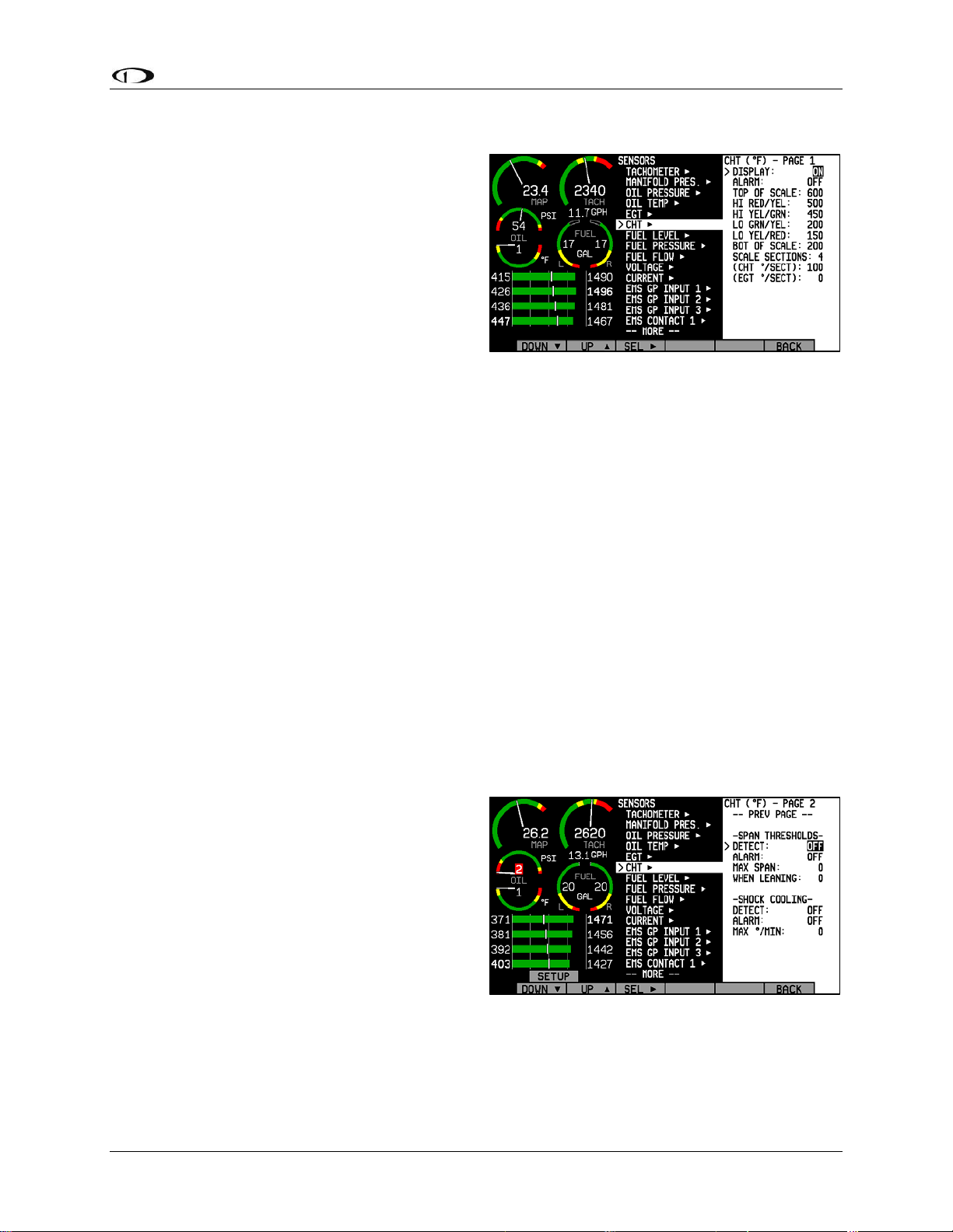
EMS Configuration
Cylinder Head Temperature (CHT)
Select the alarm mode and the analog bar
thresholds as described in Alarm and Color
Threshold Configuration on page 6-2. If one or
more CHT s
DISPLAY parameter to ON; if no CHT sensors
are installed, set it to OFF. If you are using Jtype thermocouples, you are finished with the
CHT configuration; there is no need to
configure a sensor type. If you have a Rotax and
are using resistive CHT sensors, refer to the
General Purpose Inputs section on page 6-16 to configure the instrum
sensors.
In addition to the configuration of the color thresholds, you can configure the top and bottom of
the EGT/CHT analog scales independently. This allows you to show a narrower region of
interest on the analog gauges to ensure easy detection of minor differences between cylinders.
The TOP OF SCALE parameter defines the highest temperature displayed on the EGT analog
gauge; The BOT OF SCALE parameter defines the lowest temperature displayed on the EGT
analog gauge; the SCALE SECTIONS defines the number of sections into which the entire scale
range is divided. Set the TOP OF SCALE, BOT OF SCALE, and SCALE SECTIONS to suit
your needs.
ensors have been installed, set the
ent to recognize your
For all SPLIT cylinder displays (2 and 4 cylinders only), you can set the SCALE SECTIONS for
EGT and CHT independent of each other. For COMBD displays, EGT and CHT SCALE
SECTIONS are tied together as the two sets of measurements are displayed on the same graph.
All 1/3 EMS displays show EGTs and CHTs in the combined view. All 1/3 EMS displays show
EGTs and CHTs in the combined view. If you have set the EGT/CHT displays to be split on 2/3
EMS pages, swapping to a 1/3 EMS will cause the EGT SCALE SECTIONS value to take
precedence over the CHT SCALE SECTIONS.
SPAN ALARMS
You may configure alarms based on the overall
temperature span between the hottest and
coolest cylinders’ CHTs. The span alarm
configuration is located on the second page;
press DOWN▼ from the bottom of page 1.
First, press SEL► to toggle the DETECT
setting to ON. Like other alarms, you can cycle
ALARM through SELF-CLEAR, LATCHING,
and OFF. See Alarm and Color Threshold
Configuration on page 6-2 for definitions of
those functions. Next, configure the MAX SPAN (the m
hottest and coolest cylinders, in the units shown at the top of the menu) during non-leaning
conditions. Next, configure the maximum span while leaning in the WHEN LEANING section.
If you do not wish to have a different span alarm value while leaning, you must still configure
this value to equal that of MAX SPAN. When the difference between your hottest and coldest
aximum temperature difference between
FlightDEK-D180 Installation Guide 6-11
Page 70

EMS Configuration
cylinders’ CHTs is greater than the MAX SPAN value (or WHEN LEANING value, when
leaning), a span alarm is triggered. When this occurs, those two CHT values will alternate
between their actual value and a SPN alert. If you have configured the ALARM setting to either
SELF-CLEAR or LATCHING, the SPN alarm will be red and will be accompanied by an alarm
bar. If you have configured ALARM to be OFF, the SPN alarm will be yellow.
SHOCK COOLING ALARMS
You may configure alarms that trigger on the rate of cylinder head cooling. Press DOWN▼ to
select DETECT, below SHOCK COOLING. Then, press SEL► to toggle the DETECT setting
to ON. Like other alarms, you can cycle ALARM through SELF-CLEAR, LATCHING, and
OFF. See Alarm and Color Threshold Configuration on page 6-2 for definitions of those
functions. Next, configure the MAX º/MIN (maximum degrees of cooling per minute) parameter
to the desired value. When any CHT’s rate of cooling exceeds this value, a shock cooling alarm
is triggered. When this occurs, the CHT(s) exceeding the defined maximum cooling rate will
alternate between their actual value and a SHK alert. If you have configured the ALARM setting
to either SELF-CLEAR or LATCHING, the SHK alarm will be red and will be accompanied by
an alarm bar. If you have configured ALARM to be OFF, the SHK alarm will be yellow.
6-12 FlightDEK-D180 Installation Guide
Page 71
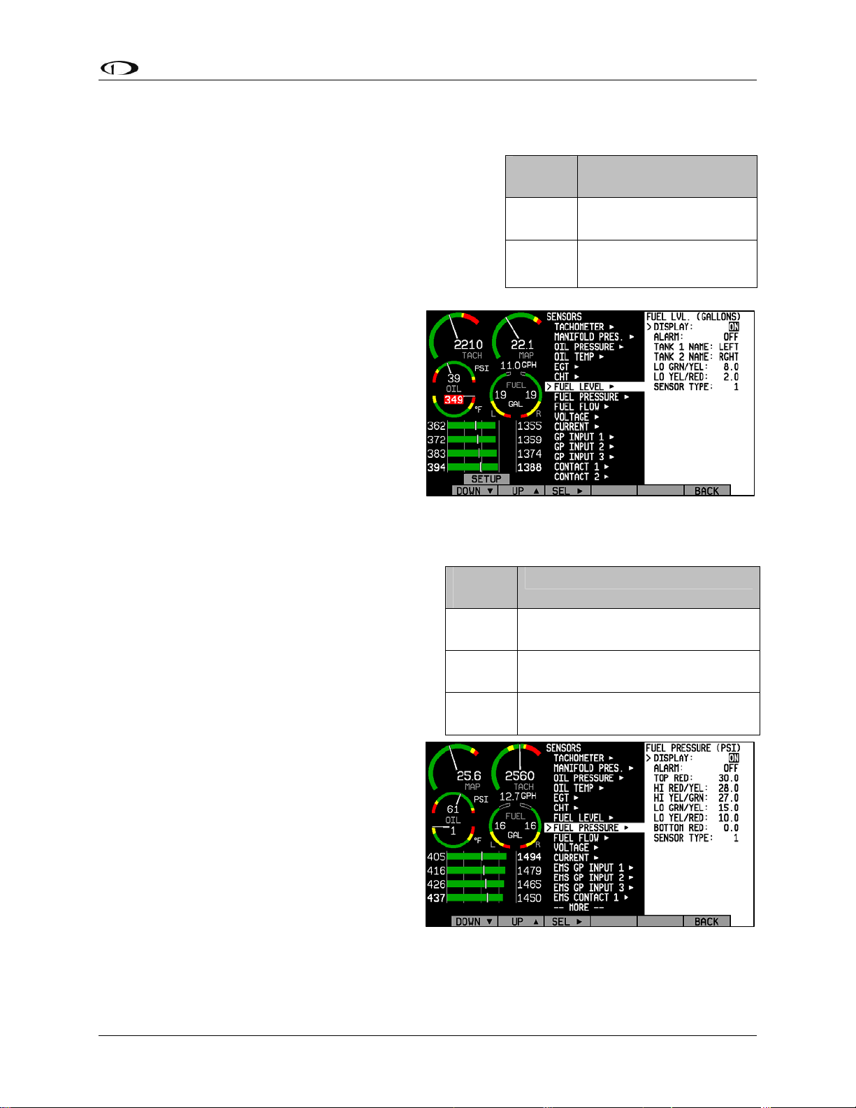
EMS Configuration
Fuel Level
If one or more fuel level transducers have been installed,
set the DISPLAY parameter to ON; if no fuel level
sensors are installed, set it to OFF. Select the alarm
mode and the analog bar thresholds as described in
Alarm and Color Threshold Configuration on page 6-2.
You may select the on-screen names for the Tank 1 and
Tank 2 inputs. You may choose from LEFT, MAIN, and
TNK1 for Tank 1. You may choose from RIGHT, AUX,
and TNK2 for Tank 2. Change the SENSOR
TYPE to the correct number using the sensor
type table.
Fuel Pressure
Sensor
Type
1
2
Fuel Level Sensor
Resistive float-type
sender
Capacitive
sender(voltage output)
If a fuel pressure transducer has been installed,
set the DISPLAY parameter to either TEXT or
DIAL. When set to TEXT, the fuel pressure
indication is displayed as a numerical value
above a graphical fuel flow dial. When set to
DIAL, the opposite is true. Note that changing
this value toggles the equivalent value in the
FUEL PRESSURE menu.
If the fuel pressure transducer has been
installed, set the DISPLAY parameter to ON,
otherwise, set it to OFF. Select the alarm
mode and the analog bar thresholds as
described in Alarm and Color Threshold
Configuration on page 6-2. Change the
SENSOR TYPE to the correct number using
the sensor type table.
Sensor
Type
1
2
3
Fuel Pressure Sensor
Dynon P/N 100411-000
(carbureted)
Dynon P/N 100411-001
(injected)
GRT LPS-02 (remove the
external pull-up resistor)
FlightDEK-D180 Installation Guide 6-13
Page 72
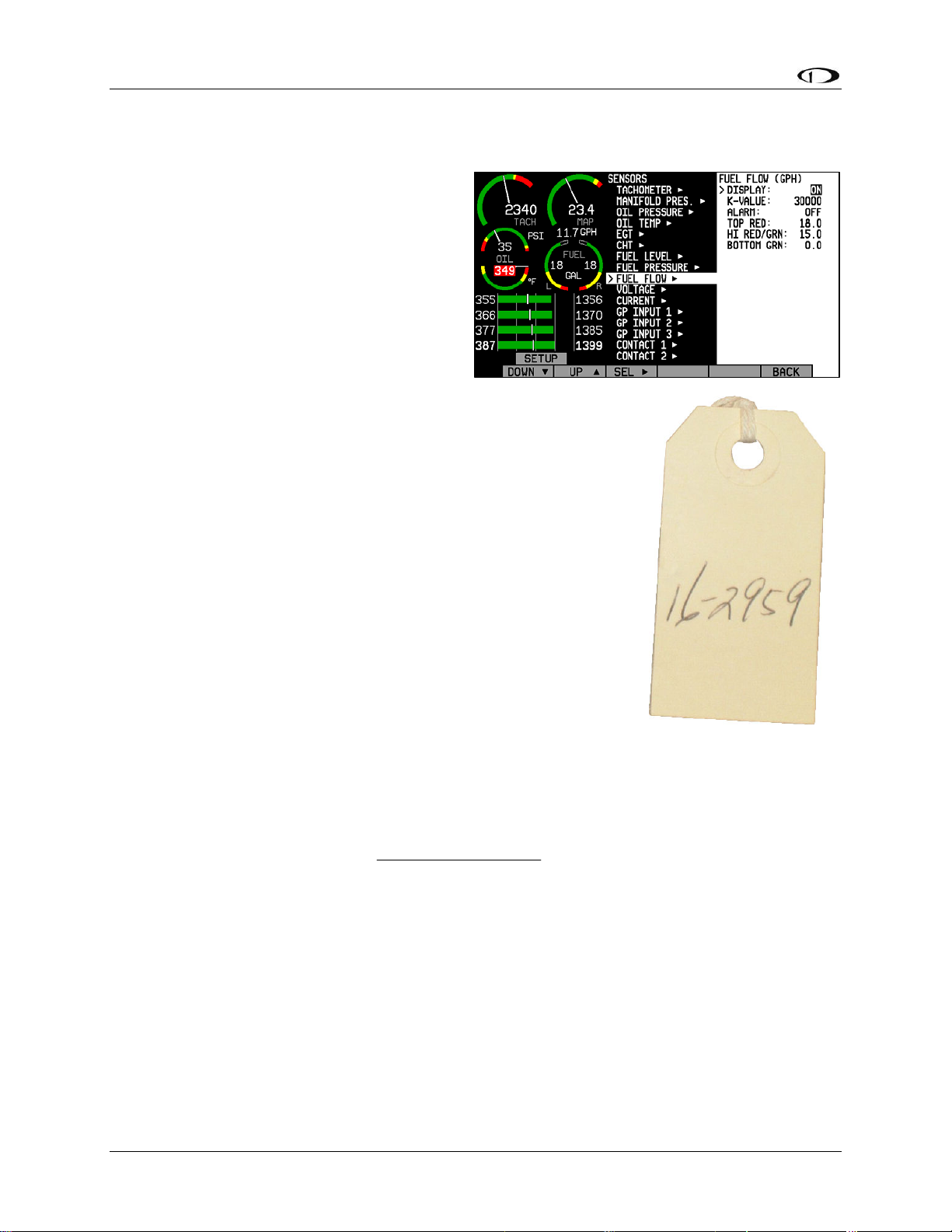
EMS Configuration
Fuel Flow
If the fuel flow transducer has been installed,
set the DISPLAY parameter to either TEXT
or DIAL. When set to TEXT, the fuel flow
indication is displayed as a numerical value
above a graphical fuel pressure dial. When set
to DIAL, the opposite is true. Note that
changing this value toggles the equivalent
value in the FUEL PRESSURE menu. Fuel
flow can also be displayed as an info bar, as
described in the FlightDEK-D180 Pilot’s User
Guide > Global Configuration Settings > Info Item Configuration
section.
Select the alarm mode and the analog bar thresholds as described in
Alarm and Color Threshold Configuration on page 6-2. Next, find the
K-value associated with your fuel flow transducer. If you have the
Floscan 201B (Dynon P/N 100403-001), this number can be found
on the tag that came with the transducer. The K-value for your
transducer is 10 times the number shown after the dash. So, if
your transducer had the tag shown at right attached to it, you would
enter a K-value of 29590 in the K-VALUE section of the Fuel Flow
configuration menu. If you have lost your tag, a starting K-value of
30000 will be close enough to begin using the function.
If you have the EI FT-60 “Red Cube” (Dynon P/N 100403-003),
enter a starting K-VALUE of 68000.
Over time, you may notice that the instrument’s computation of
gallons or liters remaining (based on fuel flow) is either high or low. This is a result of many
factors, including individual installation. To correct for this, follow this procedure:
Over several fill-ups keep a running total of the amount of fuel added. Keep a running total of
the GALS (or LTRS) USED parameter over this same time span.
Perform the following calculation:
close to 1. We’ll call this number, KFactorRatio.
Now perform this calculation: CurrentKFactor*KFactorRatio. Enter this number as your new K-
Factor.
Observe the results over your next tank for accuracy. Repeat the above if necessary.
The general rule of thumb: if your GALS (or LTRS) USED reads higher than you expect,
increase the K-factor; if it reads lower than you expect, decrease the K-factor.
If the GLOBAL > ENGINE TYPE setting is set to ROTAX, a return flow (RETRN FLOW)
setting is available in this menu. This function is generally used only by Original Equipment
Manufacturers (OEMs).
computedFuelUsed
actualFuelFilled
)(
. You should obtain a number that is
)(
6-14 FlightDEK-D180 Installation Guide
Page 73

EMS Configuration
Voltage
The voltmeter info item reports the voltage that the FlightDEK-D180 reads on its Master Power
input (pin 1 on the EFIS 25-pin connector). Because of this, there is no sensor to install or
configure. Simply, select the alarm mode and the analog bar thresholds as described in Alarm
and Color T
the desired location(s), as described in the FlightDEK-D180 Pilot’s User Guide > Global
Configuration Settings > Info Item Configuration
hreshold Configuration on page 6-2. Configure the voltmeter inf
section.
o bar to display in
Current
If a current sensor has been installed, set the DISPLAY
parameter to ON, otherwise, set it to OFF. First, select
whether your ammeter will be showing positive and
negative currents (-60A TO 60A; used for Location A)
or only positive currents (0A TO 60A; used for
Locations B and C). This will depend on your
installation as mentioned in the Ammeter
Shunt installation section on page 3-12. Select
the alarm
as described in Alarm and Color Threshold
Configuration on page 6-2. Change the
SENSOR TYPE to the correct num
the sensor type table. Configure the ammeter
info bar to display in the desired location(s),
as described in the FlightDEK-D180 Pilot’s
User Guide > Global Configuration Settings >
Info Item Configuration
If you are using the GRT CS-01 Hall effect sensor, you m
sensor. After you have selected a SENSOR TYPE of “2,” the OFFSET parameter will be
displayed. Adjust the OFFSET (in increments of 1 amp) until the current displayed on the EMS
Main page screen is correct at a known current.
mode and the analog bar thresholds
ber using
section.
Sensor
Type
1 Dynon P/N 100412-000
2 GRT CS-01
ay need to set the zero-point of the
Ammeter Sensor
FlightDEK-D180 Installation Guide 6-15
Page 74

EMS Configuration
General Purpose Inputs
In each of the 3 EMS GP INPUT submenus,
you must select the function corresponding to
the sensor that is installed for the respective
GP connection. Ensure that you have
configured your info items on the main and
aux pages to display the desired GP inputs.
Note that each GP menu will have help text,
reading “DISPLAYED: INFO #” for each
info item position where the given GP
parameter is displayed. If the given info item
is not configured to display anywhere, no text
will be shown. Configure the info item (bar, text, or flaps/trim) for each GP input to display in
the desired location(s)s, as described in the FlightDEK-D180 Pilot’s User Guide > Global
Configuration Settings > Info Item Configuration
section.
The General Purpose Inputs listed below the HS34 INPUTS section, (HS34 GP INPUT 1,
2, 3) can only be used with an HS34 installed and configured
We recommend that you set the FUNCT for all unused GP inputs to UNUSED.
ROTAX CHT
Select GP INPUT 1 and press SEL► to change the FUNCT parameter to ROTAX CHT L. Back
out and select GP INPUT 2 and press SEL► to change the FUNCT parameter to ROTAX CHT
R. Refer to the Cylinder Head Temperature (CHT) setup section on page 6-11 for information
about changing the various CHT-related param
RESISTIVE FUEL LEVEL
Under the desired GP input number, set FUNCT to FUEL LVL 3 or FUEL LVL 4 (if FUEL
LVL 3 has already been chosen on a different GP input). All fuel level inputs use the same alarm
settings. Configure these as described in the Alarm and Color Threshold Configuration section
on page 6-2.
CARBURETOR TEMPERATURE
Under the desired GP input number, set FUNCT to
CARB TEMP. Select the analog bar thresholds as
described in the Alarm and Color Threshold
Configuration section on page 6-2. Set the
SENSOR TYPE to the correct num
sensor type table.
ber using the
eters.
Sensor
Type
1
2 GRT CARB-01
3
Carburetor Temp Sensor
Dynon P/N 100413-000
(with black wires)
Dynon P/N 100468-000
(with white/black wires)
6-16 FlightDEK-D180 Installation Guide
Page 75

EMS Configuration
COOLANT TEMPERATURE
Under the desired GP input number, set FUNCT to
COOL TEMP. Select the analog bar thresholds as
described in the Alarm and Color Threshold
Configuration section on page 6-2. Set the SENSOR
TYPE to the correct number using the sensor type table.
COOLANT PRESSURE
Under the desired GP input number, set FUNCT to
COOL TEMP. Select the analog bar thresholds as
described in the Alarm and Color Threshold
Configuration section on page 6-2. Set the SENSOR
TYPE to the correct number using the sensor type table.
OUTSIDE AIR TEMPERATURE SENSOR
Under the desired GP input number, set FUNCT to
OAT. Select the analog bar thresholds as described in
the Alarm and Color Threshold Configuration section on
page 6-2. Set the SENSOR TYPE to the correct number
using the sensor type table.
If you have installed a D
ynon Avionics OAT to a
General Purpose Input enter the EMS setup menu by
pressing SETUP > SENSOR > EMS GP INPUT. Set the
desired GP Input to OAT and select sensor type 1.
Sensor
Type
Coolant Temp
Sensor
1 Dynon P/N 100409-001
2
Chevrolet LS7 pre-
installed
3 Dynon P/N 100409-000
4 Rotax 801-10-1
Sensor
Type
Coolant Pressure
Sensor
1 Dynon P/N 100411-000
Sensor
OAT Sensor
Type
Dynon P/N 100433-000
(2-wire)
1
Dynon P/N 100433-001
(3-wire, when installed
as described on page 3-
13)
2 GRT OAT-01
If the OAT is connected to the EMS D37
connector, do not set the sensor type in the EFIS > SETUP > OAT menu. Ensure that the
INSTALLED value in the EFIS OAT menu is set to N.
AILERON TRIM
Under the desired GP input number, set FUNCT to TRIM AILRN. There are no alarm thresholds
or any other setting required for aileron trim.
ELEVATOR TRIM
Under the desired GP input number, set FUNCT to TRIM ELEV. There are no alarm thresholds
or any other setting required for elevator trim.
RUDDER TRIM
Under the desired GP input number, set FUNCT to TRIM RUDR. There are no alarm thresholds
or any other setting required for rudder trim.
FLAP POSITION
Under the desired GP input number, set FUNCT to FLAP POS. There are no alarm thresholds or
any other setting required for flap position.
FlightDEK-D180 Installation Guide 6-17
Page 76

EMS Configuration
GENERAL PURPOSE TEMPERATURE
Under the desired GP input number, set FUNCT to GP
TEMP. Select the analog bar thresholds as described in
the Alarm and Color Threshold Configuration section on
page 6-2. Set the SENSOR TYPE to the correct number
using the sensor type table.
Press DOW
character of the 4-character name is highlighted. Press
INC+ or DEC- to cycle through the numbers and letters
for the first character. When you have selected the
desired letter, press SEL► to move to the next character.
Repeat this for each of the characters in the contact name
field. If desired, repeat this for LABEL 2. If you leave LABEL 2 with its default “----” value, the
temperature units are displayed beneath the temperature bar’s label; otherwise, the value of
LABEL 2 is displayed.
N▼ to select the LABEL 1 field. The first
Sensor
Type
1
2 GRT OAT-01
GP Temp Sensor
Dynon P/N 100433-000
(2-wire)
Dynon P/N 100433-001
(3-wire, when installed
as described on page 3-
13)
Contacts
Note that while contacts are shown below the HS34 INPUTS section, they are not available until
you purchase and connect an HS34 expansion module. Ensure you are configuring in either of
the two EMS CONTACT menus.
To access the CONTACTS configuration page, select EMS > SETUP > SENSOR > EMS
CONTACT 1 or CONTACT 2.
Select the alarm mode as described in the Alarm and Color Threshold Configuration section on
page 6-2. Contacts can only be configured as an INFO ITEM. Configure the contacts info item
display in the desired location(s), as described in the FlightDEK-D180 Pilot’s User Guide >
Global Configuration Settings > Info Item Configuration
Press DOWN▼ to select the NAME field that you want to appear for CONTACT (1 or 2). The
first character of the 4-character name is highlighted. Press INC+ or DEC- to cycle through the
numbers and letters for the first character. When you have selected the desired letter, press
SEL► to move to the next character. Repeat this for each of the characters in the contact name
field.
Press DOWN▼ to select CLSD LABEL. The label you enter here will be shown
when CONTACT (1 or 2) is closed (connected to ground). Select CLSD COLOR
and press SEL► until the desired color for a closed contact is displayed. Repeat
these two steps for OPEN LABEL (label shown when contact is disconnected from
ground) and OPEN COLOR.
Contact alarm triggering is based on the colo
of the states. If you have selected a SELF-CLEAR or LATCHING alarm for a
contact and it enters a state selected to be RED, the EMS will display the alarm bar
and the contact label will blink onscreen.
r selected in the COLOR field for either
section.
The Contact Inputs listed below the HS34 INPUTS section, (HS34 CONTACT 1, 2, 3, 4)
can only be used with an HS34 installed and configured.
to
6-18 FlightDEK-D180 Installation Guide
Page 77

EMS Configuration
General Purpose Thermocouple
Select the alarm mode as described in the Alarm and
Color Threshold Configuration section on page 6-2.
Configure the GP therm
desired location(s), as described in the FlightDEK-D180
Pilot’s User Guide > Global Configuration Settings >
Info Item Configuration
After configuring alarms, press DOWN▼ to select the LABEL 1 field. The first character of the
4-character name is highlighted. Press INC+ or DEC- to cycle through the numbers and letters
for the first character. When you have selected the desired letter, press SEL► to move to the
next character. Repeat this for each of the characters in the contact name field. If desired, repeat
this for LABEL 2. If you leave LABEL 2 with its default “----” value, the temperature units are
displayed beneath the temperature bar’s label; otherwise, the value of LABEL 2 is displayed. Set
the SENSOR TYPE to J or K, depending on the thermocouple type used.
ocouple info bar to display in the
section.
Sensor
Type
J J Type Thermocouple
K K Type Thermocouple
GP Temp Sensor
FlightDEK-D180 Installation Guide 6-19
Page 78

Page 79

7. DSAB CONFIGURATION
This section introduces some concepts that are central to understanding and configuring a
network of DSAB-capable Dynon products. It then takes you through a series of simple steps to
configure your network, enabling data sharing and HS34 functionality. Do not proceed with
DSAB configuration until you perform all installation, calibration, and configuration steps for
each instrument with a display. Display-less instruments – such as the HS34 – cannot be fully
configured until DSAB is active, although their physical and electrical installation should be
complete.
Network Concepts
A few concepts must be
understood before
configuring a DSABconnected system. The
most important is that of
Dynon products as
providers of functions to
the network. These
various functions are
called
products, such as the
HS34, only have one role
on the network; other
products can provide
multiple roles at a time.
When a device has been
assigned to provide a role
to the network, no other
device on the network can
provide that role at the
same time.
roles. Some
Assignable
roles by
product
Bus Master
EFIS
EMS
OAT
Compass
HS34
Autopilot
AP Control
Panel
AP
Roll/Pitch
Servo
EFIS-D10A/
EFIS-D100
EMS-D10/
EMS-D120
FlightDEK-
D180
X X
X X
X X
X X X
X X
X
X X
X
X
HS34
SV32/42/52
AP74
The table at right lists all available roles and the products which they can be assigned to. Again,
each ro
Another important concept is that of the
least one EFIS-based product (EFIS-D10A, EFIS-D100, or FlightDEK-D180), and only an EFISbased product can be assigned the Bus Master role. The Bus Master is the instrument which
manages communication on the network. Additionally, if Autopilot servos are installed, the Bus
Master is the Autopilot. While the Autopilot can be controlled from slave devices, if the Bus
Master is not present, the Autopilot will not function. If the Bus Master is turned off or fails, all
data sharing ceases, causing units to display internally-derived data only. When you first perform
DSAB network configuration on an EFIS-based instrument, that device is automatically assigned
the Bus Master role. Perform DSAB configuration on your primary EFIS-based instrument, as
the Bus Master is also the default provider for both the EFIS and Compass roles.
FlightDEK-D180 Installation Guide
le can be assigned to no more than one device on the network.
Bus Master. A DSAB-connected network must have at
7-1
Page 80
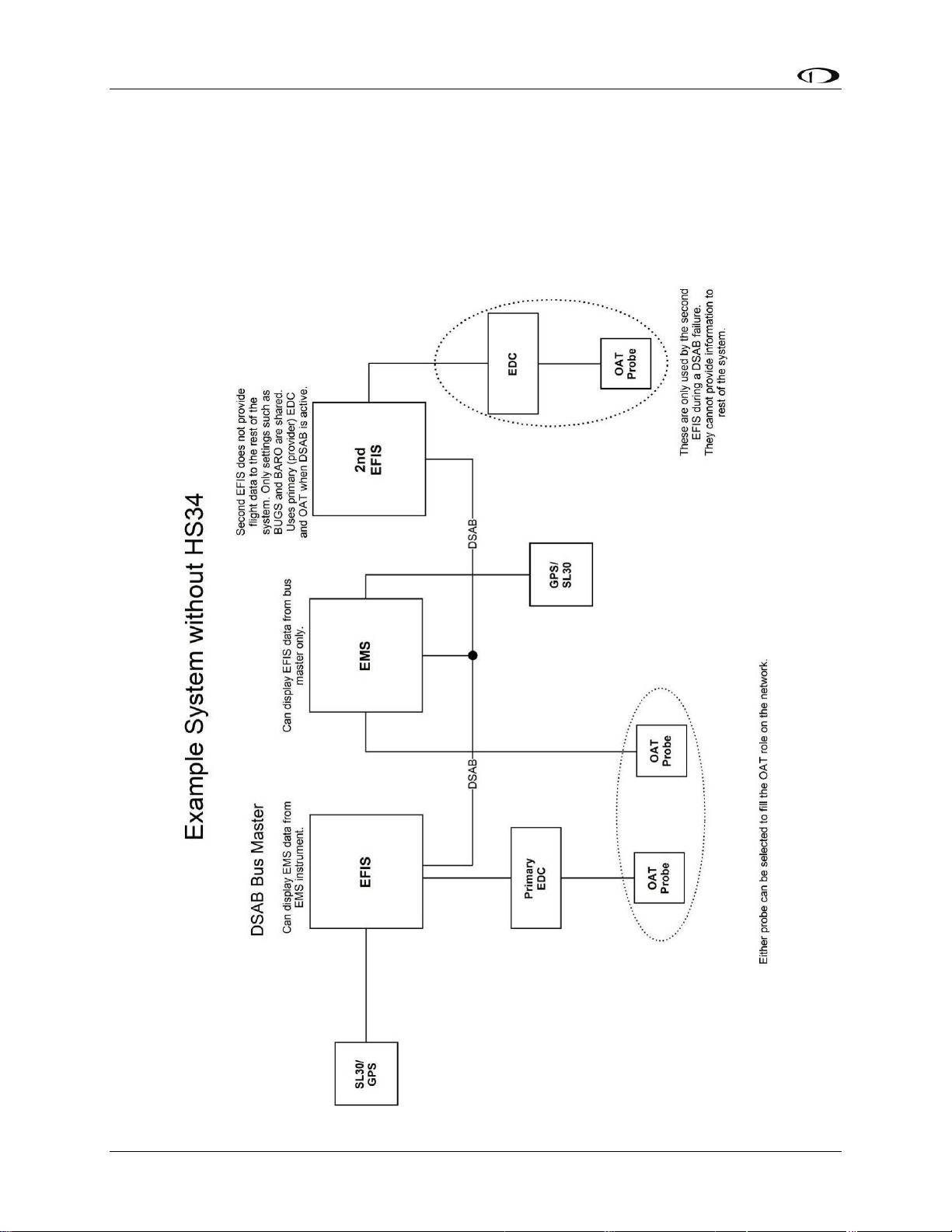
DSAB Configuration
Example Networks
The following two diagrams present example DSAB-connected networks. These examples
illustrate and expand upon some of the concepts discussed above. The first diagram depicts a
system without an HS34 connected, demonstrating where NAV and GPS devices should be
connected. The second diagram depicts a system with an HS34 connected, demonstrating that all
NAV and GPS devices must be connected to the HS34. Both diagrams discuss what devices can
be assigned various roles and what happens when DSAB fails.
7-2 FlightDEK-D180 Installation Guide
Page 81
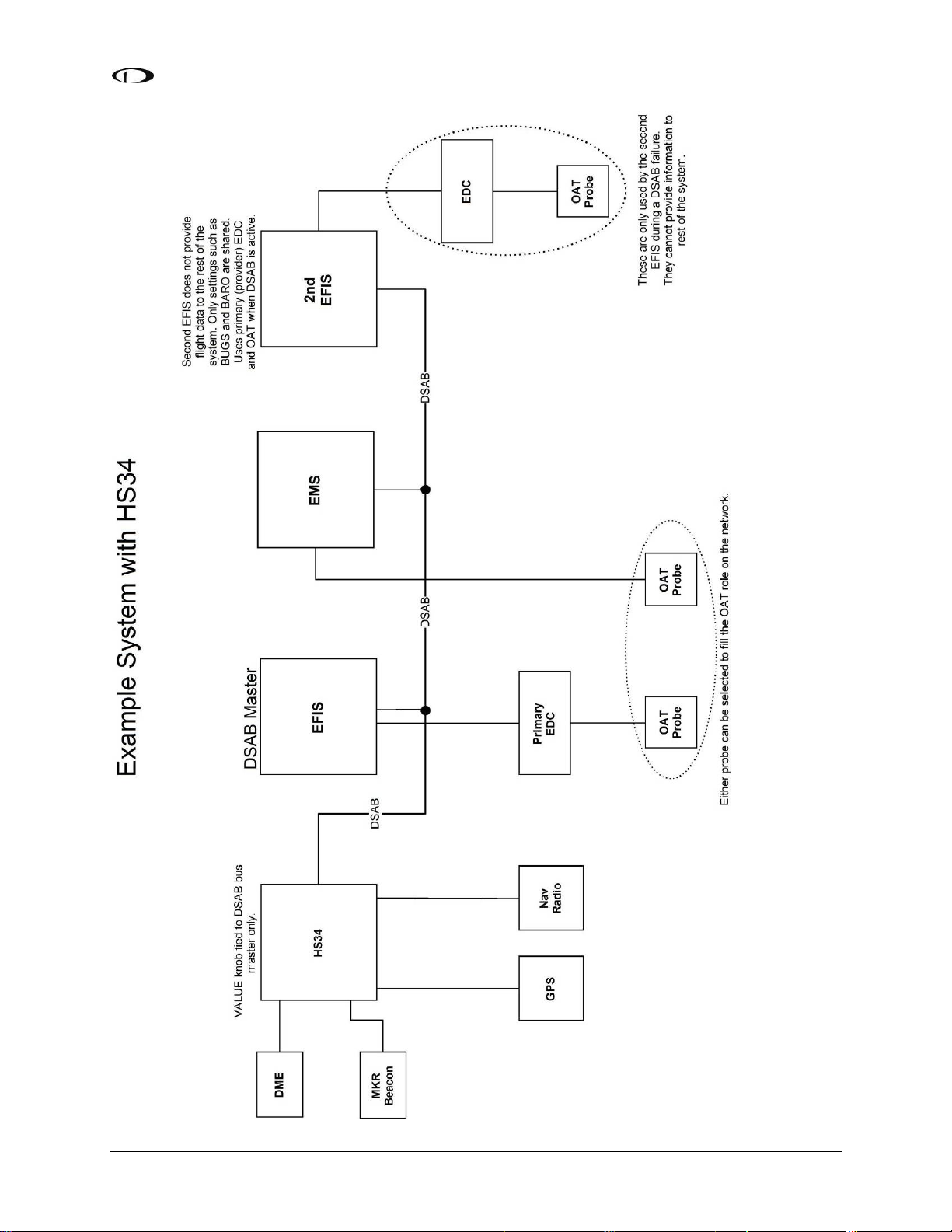
DSAB Configuration
FlightDEK-D180 Installation Guide 7-3
Page 82

DSAB Configuration
Initial Setup
As mentioned at the beginning of this chapter, configure your DSAB network only after all other
installation steps have been performed, including updating all products to the latest version of
firmware available from the Dynon Avionics web site at downloads.dynonavionics.com
begin configuration, enter the EFIS > SETUP > DSAB menu. A full-page menu appears with
three options: STATUS, CONFIGURATION, and BRIGHTNESS. Push DOWN▼ to select
CONFIGURATION and then SEL► to enter the CONFIGURATION submenu. Note that if you
press CONFIGURATION from an EMS-only product (via EMS > SETUP > DSAB), the display
prompts you to begin the configuration process from an EFIS-based product.
If this is not your first time configuring your DSAB network, a prompt appears asking if you
wish to re-configure the network. If you do not want to re-configure, press NO; otherwise, press
YES to proceed with configuration as if this is a first-time install.
The first screen in the configuration process asks you to power on all devices in the system
before pressing CONFIGURE NOW (button 1 or 2). After doing this, a second screen appears
asking you to wait while the instrument detects all other devices connected via DSAB. While
doing this, it assigns both the Bus Master and EFIS roles to itself.
During network detection, the Bus Master attempts to automatically assign as many roles as it
can. The following table describes the logic used in assigning roles for network devices.
. To
Bus Master
EFIS
EMS
OAT
Compass
AP CTRL
PANEL
HS34
How role is assigned
Auto-assigned to instrument user is configuring on.
Auto-assigned to instrument user is configuring on.
If one EMS detected, assigned automatically.
If Bus Master is EMS (i.e., FlightDEK-D180) assigned automatically.
If more than one non-bus-master EMS detected, user must assign.
If one OAT detected, assigned automatically.
If more than one OAT detected, user must assign.
Note that for an OAT to be used it must be connected to an instrument
assigned the EFIS or EMS role (i.e., if configuring DSAB on a
FlightDEK-D180 with no OAT attached, the OAT role cannot be assigned
to another instrument in the system as the FlightDEK-D180 is already
assigned both the EFIS and EMS roles).
Auto-assigned to instrument providing the EFIS/Bus Master roles.
If one AP74 detected, assigned automatically.
If more than one AP74 detected, error displayed: Not a supported
configuration.
If one HS34 detected, assigned automatically.
If more than one HS34 detected, error displayed: Not a supported
configuration.
7-4 FlightDEK-D180 Installation Guide
Page 83

DSAB Configuration
Roll Servo and Pitch Servo functions are automatically detected and
AP
ROLL/PITCH
SERVO
If the configuration process could not automatically assign the EMS and OAT roles (because
there are 2 or more of either type found on the network), it prompts you to assign each of them to
the instrument of your choice. It then presents a list of all instruments on the network capable of
being assigned each role. Use the DOWN▼ and UP▲ buttons to select the preferred instrument
to provide the given role. The serial number for each unit is displayed next to its product type.
Additionally, with an instrument type selected, pressing IDENT changes that instrument’s
display to a black screen with the text DSAB IDENT shown. If the instrument you wish to
identify is the one which you are currently interacting with, the line changes to read THIS UNIT.
When you have selected the preferred provider for the role, press SELECT to continue in the
process. If necessary, repeat with the next manually assigned role.
At this point, a screen is displayed, stating:
(X) DEVICES FOUND
NETWORK CONFIGURATION IS COMPLETE
assigned during Autopilot Servo Calibration process. See: EFIS > SETUP
> AP > SERVO CALIB.
More than two SV32s or SV42s is not a supported configuration.
Press FINISH to end the configuration. Press UP▲ and SEL► to view the status of all
connected DSAB devices. Press UP▲ or DOWN▼ to scroll through all the devices. Crosscheck the displayed devices against what you actually have installed and connected. Ensure that
the STATUS for each device is listed as ACTIVE.
You may repeat the configuration process as many times as you wish. Whenever you add or
remove an instrument from your network, you must redo the DSAB configuration process.
Note that the following DSAB configurations are not supported:
More than 1 FlightDEK-D180 in the network
More than 1 HS34 in the network
More than 1 AP74 in the network
More than 2 servos in the network
Brightness Configuration
In a DSAB network, changing the brightness level of one instrument affects all connected
instruments. Dynon Avionics sells D100-series instruments with both regular and bright screens.
Each instrument connected to your DSAB network must have its display type configured to
ensure that perceived brightness matches across all screens. To do this, enter the SETUP >
DSAB > BRIGHTNESS menu on each product in the system. If you purchased the bright screen
option for your FlightDEK-D180, press TOGGLE to change the BRIGHT SCREEN status to
YES. Otherwise, ensure this is set to NO.
If the DIM setting of one of the screens in a DSAB network gets “out of sync” (some
dim, some bright), this can be corrected by adjusting the DSAB Bus Master screen to the
desired DIM and then performing a DSAB CONFIGURE.
FlightDEK-D180 Installation Guide 7-5
Page 84
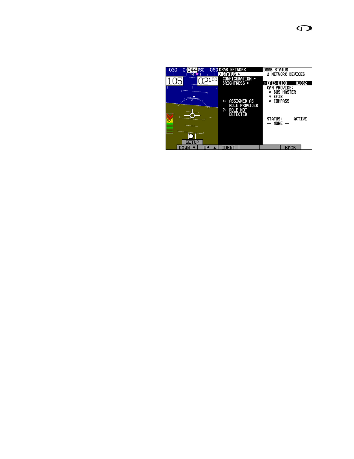
DSAB Configuration
Network Status
The STATUS submenu displays
information on all configured devices,
their serial numbers, their roles on the
network, and their status.
irst line indicates how many devices
The f
are configured on the network. This
number is independent of the number of
devices actually currently turned on and
communicating. It simply reports how
many instruments were present during the
most recent execution of DSAB
configuration.
The next several lines indicate the available roles that the selected instrument can provide. A “*”
is placed next to the roles that the instrument is currently providing to the network. If any of
those roles cannot be detected (e.g., the EFIS’s compass has been disconnected), a “?” is
displayed next to that role. Any given instrument in the list can have one of the following
STATUS messages:
ACTIVE – The device is communicating normally on DSAB.
STANDALONE – During configuration as Bus Master, no other DSAB devices were found.
UPGRADE REQ – Device has a different firmware version than the Bus Master and thus
cannot communicate on DSAB.
OFFLINE – The specified device cannot communicate on DSAB or is powered off.
PEERS LOST – (Only appears on Bus Master) – The Bus Master was configured with other
DSAB devices present; however, all of them are currently offline.
If an instrument’s STATUS field displays UPGRADE REQ, PEERS LOST, or OFFLINE, all of
its provided roles are listed as not detected.
The selected instrument’s serial number is displayed, assisting in identification. Additionally,
pressing IDENT causes the selected instrument’s display to display a black screen with the text
DSAB IDENT shown. If the instrument you wish to identify is the one which you are currently
interacting with, the line changes to read THIS UNIT.
Press DOWN▼ or UP▲ to scroll through each of the other instruments configured in your
network.
7-6 FlightDEK-D180 Installation Guide
Page 85

8. AUTOPILOT INSTALLATION AND CONFIGURATION
Dynon Avionics’ Autopilot (AP) system is a competitively priced product for the Experimental
& Light Sport Aircraft (LSA) aircraft market. Unlike standalone AP systems, Dynon’s AP is an
enhancement to the Dynon Avionics EFIS-D10A, EFIS-D100, and FlightDEK-D180 products
(beginning with firmware version 5.0). The Dynon Avionics AP provides roll (aileron) and/or
pitch (elevator) control, leveraging the proven sensors, algorithms, and display systems of
Dynon’s modern EFIS products. Another innovative element of the Dynon Avionics AP is that
the servomotors (servos) responsible for actuating the control surfaces are “smart” devices.
Dynon’s servos not only accept commands from the AP but also report “health,” resistance to
commanded movements, motor override (or “slip”), and many other data elements back to the
EFIS. This level of communication between AP control and motors provides the pilot with an
unprecedented degree of awareness of the overall performance of the AP. Dynon currently offers
the following servo models:
Model Number Torque Attachment
SV32 Standard Arm
SV32L Long Arm
SV32C
SV42 Standard Arm
SV42L* Long Arm
SV42C
36 inch-pounds
Capstan
55 inch-pounds
Capstan
* SV42L servo is a special order item – contact Dynon Technical Support for details.
Dynon also offers the AP74 Autopilot Interface Module, which provides dedicated AP
control via panel-mounted buttons and a knob. Dynon offers mounting kits for specific
airframes, which include parts and detailed instructions. Additionally, Dynon Avionics
supplies a generic mounting kit of basic parts that provides a head start for owners of aircraft
not currently supported by our specific kits.
Additional Information and Updates
This guide provides generic mechanical installation guidelines to assist installers while
integrating the Autopilot system into many aircraft. If you purchased a plane-specific kit from
Dynon Avionics, it contains more detailed drawings and diagrams unique to your aircraft. You
can find the list of Dynon’s aircraft mounting kits on the current
Dynon’s secure web site at store.dynonavionics.com
of current Dynon Avionics aircraft mounting kits are available on the Dynon web site at
docs.dynonavionics.com
Because the Dynon Avionics Autopilot is a new product and we expect that it will be installed in
a wide variety of aircraft, Dynon’s Internet sites provide up-to-date information on installation
and operation issues:
wiki.dynonavionics.com
continuously-updated online documentation contributed by Dynon employees and customers.
.
– Dynon’s Documentation Wiki provides enhanced, extended,
. The drawings and installation instructions
Price List / Order Form on
FlightDEK-D180 Installation Guide
8-1
Page 86

Autopilot Installation and Configuration
forum.dynonavionics.com – Dynon’s Online Customer Forum is a resource for Dynon Avionics
customers to discuss installation and operational issues relating to Dynon Avionics products. The
Forum is especially useful for pilots with uncommon aircraft or unusual installation issues. For
customers that cannot call Dynon Technical Support during our normal business hours, the
Forum is a convenient way to interact with Dynon Avionics Technical Support. The Forum
allows online sharing of wiring diagrams, photos, and other types of electronic files.
Dynon will continue to develop kits and installation instructions for more aircraft based on
demand. It is also expected that aircraft manufacturers will develop their own mounting kits for
Dynon servos or offer the Dynon AP as a factory option. If Dynon does not currently offer a
mounting kit for your particular aircraft, and you would be inclined to assist in developing a kit
and documentation, please send an introductory email message about your interest to:
betatest@dynonavionics.com
.
DSAB Firmware Compatibility
All Dynon instruments connected via DSAB must be running the same firmware version
(currently version 5.4). This applies to the servos and AP74 as well. Because the servos
and AP74 are updated via the DSAB Bus Master EFIS (the EFIS that you wish to control
the AP, and from which you run the CONFIGURE DSAB command), wait until
complete mechanical and electrical installation before performing the software upgrade
steps. See Firmware Upgrades Required For AP Functionality on page 8-13 for more
inf
ormation.
Compass Calibration Critical For Certain AP Modes
The Dynon Avionics AP requires an accurate magnetic heading to operate efficiently and
comfortably in HDG mode and the radio-based VOR/NAV mode. Therefore it is critical
that the aircraft’s compass be installed correctly, calibrated, and operating well in all
attitudes. If you currently have an EFIS-D10A, and are only using the internal magnetic
compass, Dynon strongly recommends the installation and use of the EDC-D10A remotemounted digital magnetic compass, and properly calibrating it per the instructions found
in Chapter 4: Instrument Installation.
If the Dynon Avionics AP will be used exclusively in GPS NAV or TRK modes, then absolute
accuracy of compass data is somewhat less critical as part of AP operation. But if NAV/GPS
data is lost due to an equipment failure, bad data, loss of signal, etc. the AP will “fail over” to
HDG mode, which uses the magnetic compass data as its source.
8-2 FlightDEK-D180 Installation Guide
Page 87
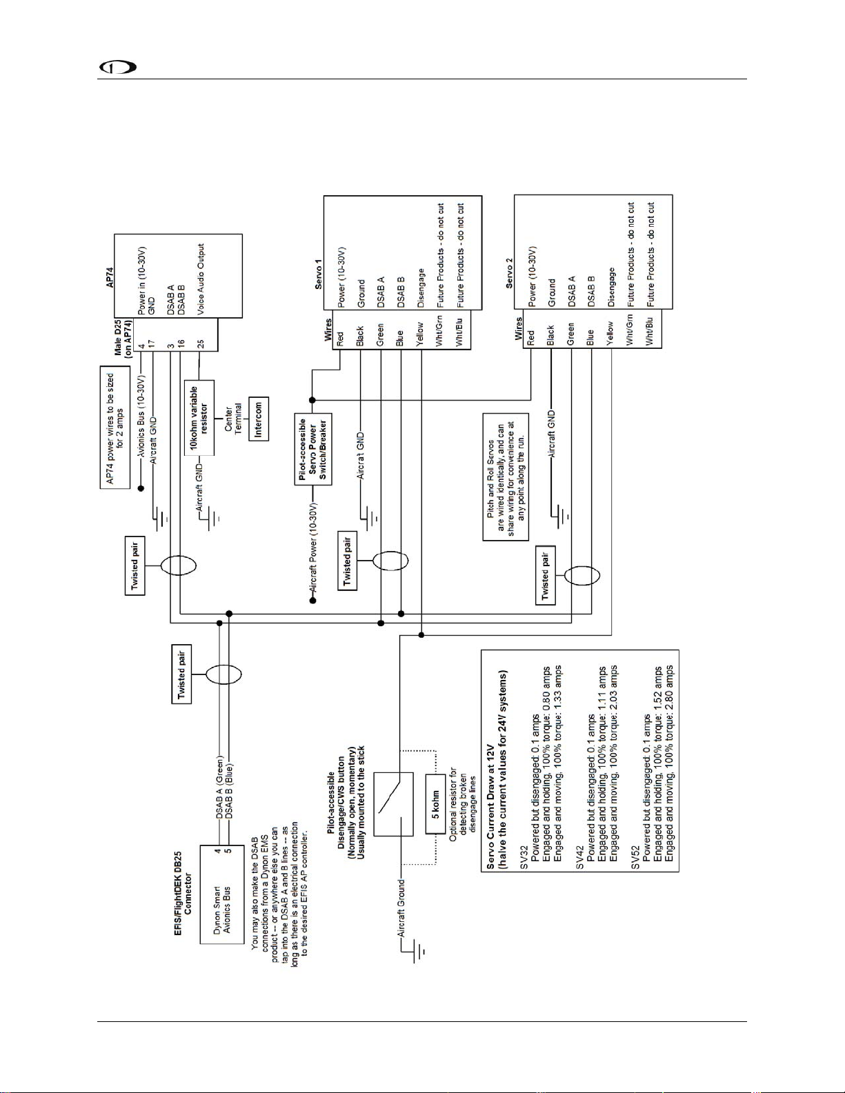
Autopilot Installation and Configuration
Autopilot System Electrical Installation
The diagram below provides an overview of the autopilot electrical system. The following
sections describe the electrical installation of each subsystem in detail.
FlightDEK-D180 Installation Guide 8-3
Page 88

Autopilot Installation and Configuration
SERVO ELECTRICAL INSTALLATION
Dynon Avionics’ servos are supplied with 7 un-terminated wires, each about 8” in length. It is
the responsibility of the installer to decide on connectors and associated wiring. The 7 wires have
the following colors and functions:
Color Function Notes
Red
Black
Green
Blue
Dynon Smart Avionics
Dynon Smart Avionics
Power 10-30 volts DC. Each servo draws up to 2 amps
Aircraft Ground Each servo draws up to 2 amps
Connected in parallel with other DSAB devices
Bus [DSAB] “A”
(Green wire on all Dynon-supplied wiring harnesses)
Connected in parallel with other DSAB devices
Bus [DSAB] “B”
(Blue wire on all Dynon-supplied wiring harnesses)
Connected through a normally-open pushbutton
switch to Ground (disengages AP when button is
pushed). If two servos are installed, the yellow wire
from each servo is connected in parallel to a single
Yellow
AP Disengage/Control
Wheel Steering (CWS)
Button
pushbutton.
DO NOT CUT! During servo installation, Dynon
recommends that this be routed to the cockpit panel
(include sufficient slack behind the panel) if you
want to preserve compatibility of the servo with
Dynon’s “Next Generation” technology. This wire is
White/Green
Reserved for
compatibility with
Dynon “Next
Generation” products
not used with the FlightDEK-D180.
DO NOT CUT! During servo installation, Dynon
recommends that this be routed to the cockpit panel
(include sufficient slack behind the panel) if you
want to preserve compatibility of the servo with
Dynon’s “Next Generation” technology. This wire is
White/Blue
Reserved for
compatibility with
Dynon “Next
Generation” products
not used with the FlightDEK-D180.
Circuit Breaker/Switch: We recommend that electrical power for the all servos be protected
with an appropriately sized circuit breaker or switch that is accessible to the pilot while in
flight.
Wire Sizing: While it is beyond the scope of this installation guide to advise on specific
types of wiring for a particular aircraft, choice of wiring should be sized to 1) minimize
voltage drop over the length of the particular wiring run, and 2) conduct the amount of
current required by the subsystem without the wiring becoming warm to the touch.
Wiring Installation: Care should be taken such that aircraft wiring is not subjected to
chafing, excessive flexing, or connections / junctions subjected to excessive vibration which
may cause the connection/junction to fail or short-circuit. If the White/Green and White/Blue
wires are extended to the cockpit panel, leave sufficient slack behind the panel for connection
anywhere behind the panel. If the White/Green and White/Blue wires are not extended to the
cockpit panel, as with other unused wires, DO NOT CUT the wires, but rather insulate the
ends of the wires (electrical tape, heatshrink tubing), bundle, and secure the unused wire.
8-4 FlightDEK-D180 Installation Guide
Page 89
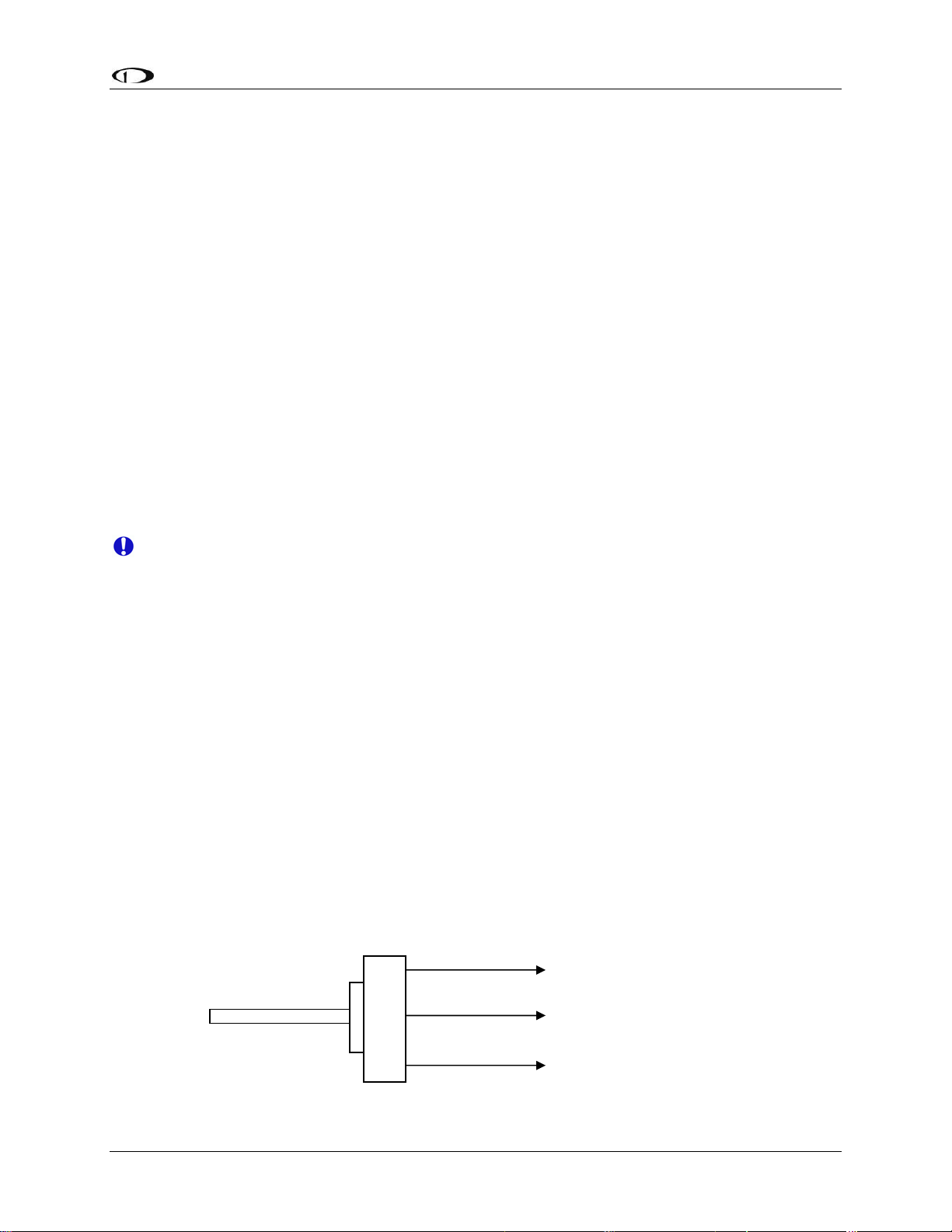
Autopilot Installation and Configuration
AP CONTROLS ELECTRICAL INSTALLATION
Circuit Breaker/Switch Install a circuit breaker or switch in a location that is accessible to the
pilot while in flight.
AP Disengage/Control Wheel Steering Button
The AP Disengage/CWS button should be in a very accessible location, usually mounted to the
stick or yoke. This button’s primary purpose is to immediately disengage the autopilot. When
configured in the EFIS > SETUP > AP > BUTTON CONFIG menu, this button can also be used
to engage the Autopilot from an “off” status by holding the button for more than 2 seconds.
This button should be a Single Pole, Normally Open, Momentary button. Verify that two
terminals of the button are shorted when the button is pressed and open (no-connect) when the
button is released. One terminal of the button should connect to both servos’ yellow wires, and
the other should connect to ground.
While not required, you may install a 5 kΩ resistor across the AP Disengage/CWS button. When
configured in the EFIS > SETUP > AP > BUTTON CONFIG > RESISTOR INST menu, the
EFIS monitors the disengage line and displays a warning when a broken connection is detected.
AP74 ELECTRICAL INSTALLATION
When installing the AP74, we recommend building enough slack wiring into the D25
connector to allow the AP74 to be removed from its tray with the connector attached.
Use the D-sub pins/connector kit included with your AP74 to make the following connections:
Pin 3: Dynon Smart Avionics Bus (DSAB) “A”, connected in parallel with all other DSAB B
connections (Blue wire on Dynon-supplied wiring harnesses)
Pin 4: Power, 10 - 30 volts DC
Pin 16: Dynon Smart Avionics Bus (DSAB) “B”, connected in parallel with all other DSAB
A connections (Green wire on Dynon-supplied wiring harnesses)
Pin 17: Aircraft Ground
Pin 25: Outer terminal of AP Audio Adjustment Potentiometer (detailed below); If HS34
installed and providing audio to your intercom system, do not connect the AP74 audio out. If
both the HS34 and AP74 Voice/Tone outputs are connected to your intercom, audio alerts
will be distorted.
Ensure that the AP74 audio output is connected similar to the following diagram. The 10 kΩ
variable resistor can be obtained from Radio Shack (P/N 271-1715) or other electronics
suppliers. The potentiometer does not need to be pilot-accessible as it is typically adjusted only
during setup and configuration. See Step 6 - Audio Alerts Configuration on page 8-23.
Outside terminal
To AP74 pin 5 - A
udio
Alert Out
Center ter
minal
To intercom/audio
panel auxiliary input.
Outside term
inal
Aircraft ground
FlightDEK-D180 Installation Guide 8-5
Page 90

Autopilot Installation and Configuration
Note: As with the optional Dynon HS34, it is acceptable to connect the tone output of EFIS
(DB25 Pin 18) and/or EMS (DB37 Pin 31) in parallel with the tone/voice output of the AP74
(Pin 25) to provide “failover” audio alerts from the EFIS and/or EMS if the AP74 were to fail.
However, do not connect the audio outputs from an HS34 and AP74 in parallel.
Servo Mechanical Installation
Dynon Avionics has researched suitable mounting points for a number of popular aircraft and
offers mounting kits and instructions for them. If you have purchased one of these kits, use the
instructions included with it as your primary guide; the following mechanical installation
information is more general in nature. If you have purchased cable-drive capstan servos (SV32C
or SV42C), refer to the documentation that came with the included Capstan Accessory Kit.
For installing Dynon Avionics servos in aircraft for which Dynon does not offer kits, we offer a
“generic” kit of basic parts and basic installation instructions: Dynon P/N 101020-000. The
generic servo push-pull mounting kit includes some of the hardware to mount a servo and
connect to the aircraft controls, but requires the installer to fabricate mounting brackets. This kit
can be used in either pitch or roll applications that use a servo with an output arm (not suitable
for use with pulley/cable servos). Some additional fasteners (not supplied by Dynon) and
brackets will be required depending on the installation method chosen.
CAUTION: Neglecting to properly install and/or use Dynon Avionics AP hardware can
result in failures which could cause loss of aircraft control resulting in aircraft damage,
personal injury, or death. If there are any questions on the part of the installer it is
mandatory to resolve these questions prior to flight.
When installing the servo, you must first determine a mount location for proper interaction with
the existing control system. The mounting point that is chosen must allow the servo arm and
associated linkage to move freely through the entire range of travel. To prevent the possibility of
the servo arm going OVER CENTER, the servo arm must not travel more than a total of +/-60º
from neutral position. When the aircraft controls are centered, the arm of the servo should be
perpendicular to the attaching push rod. If this is not the case, we recommend adjusting the
length of the push rod or consider a different mounting point. For maximum efficiency and the
lightest drag on the flight controls, you should choose the smallest servo that provides sufficient
torque to move and hold the flight controls with a minimum of “slippage”. A diagram of servo
torque versus mount position is shown on page 8-9.
CAUTION: The servo arm must not rotate even near to the point called OVER
CENTER
happens when the angle between the servo arm and the attached push rod becomes so
great that the control system cannot drive against the servo arm. To protect against this
possibility, a Range of Motion Limiting Bracket is supplied with each Dynon Avionics
servo. These brackets are drilled so that they can be mounted at different angles as
required (18° intervals). The brackets are supplied for the protection of the pilot, and we
recommend that the Range of Motion Limiting Bracket be installed to ensure that an
OVER CENTER condition cannot occur.
, the point at which the primary aircraft control would “lock up”. Over center
Once a suitable mounting point for each servo has been determined, the next step is to fabricate a
mount for the servo to attach to the aircraft. Generally this will be a bracket made of sheet metal
8-6 FlightDEK-D180 Installation Guide
Page 91

Autopilot Installation and Configuration
or corner stock. Dynon recommends using 6061 T6 aluminum with a minimum thickness of
0.050” for the best balance of strength to weight. When fabricating a mounting bracket, refer to
the servo dimensions below. Be sure to leave ample room for the arm and attached linkage to
move through a complete range of motion without interference.
CAUTION: In normal operation, Dynon’s servos can reach temperatures that can be
very uncomfortable to, and perhaps cause burns to unprotected skin. Thus, servos should
be mounted in an area, or in such a manner to prevent accidental skin contact. If
mounting the servo in an exposed area is necessary, a shroud should be installed (that
doesn’t restrict ventilation) that protects against accidental skin contact with the servos.
FlightDEK-D180 Installation Guide 8-7
Page 92

Autopilot Installation and Configuration
PUSH-PULL SERVO DIMENSIONS
Use the following dimensions (in inches) for reference when planning and implementing your
installation.
Long-arm variants
(not needed in most
installations) have
linkage mount holes
at 1.5”, 1.75”, and
2.0”
L Weight
SV32 2.17” 2 lb
SV42 3.10” 3 lb
SV52 4.02” 4 lb
8-8 FlightDEK-D180 Installation Guide
Page 93

Autopilot Installation and Configuration
LINKAGE MOUNT POSITION FORCE AND TRAVEL
The two diagrams below illustrate the maximum travel and force available at each linkage
mounting point. As can be seen, the closer you mount the linkage to the shaft, the more force the
servo can deliver. However, this also means the travel of the arm is shorter. Again, ensure that
the servo arm is nowhere near going over-center throughout the entire range of the control
system.
Standard Arm
Max Linear Travel
A: 2.6”, B: 2.2”, C: 1.8”
Max Force @ 100% Torque
SV32 - A: 24lb, B: 29lb, C: 36lb
SV42 - A: 36lb, B: 44lb, C: 55lb
SV52 - A: 48lb, B: 58lb, C: 72lb
Long Arm
Max Linear Travel
A: 3.4”, B: 3.0”, C: 2.6”
Max Force @ 100% Torque
SV32L - A: 18lb, B: 20lb, C: 24lb
SV42L - A: 27lb, B: 31lb, C: 36lb
SV52L - A: 36lb, B: 41lb, C: 48lb
ost instances, we recommend that you connect the servo arm to the control linkages using
In m
the outer-most hole of the servo arm (position A). This position provides the greatest amount of
travel, with the least amount of drive force. If, when testing the autopilot, you find that the servos
cannot adequately drive the control system (indicated by a yellow “slip indicator” in the AP
status at the bottom left of the EFIS screen), you may move the linkage mount point inward,
provided there is still enough travel to accommodate the control system at the servo location.
Using either of the two inner-most holes of the servo arm affects the final amount of force that
FlightDEK-D180 Installation Guide 8-9
Page 94

Autopilot Installation and Configuration
the servo can exert, arm travel, control surface resolution, and the amount of force required to
shear the brass shear screw. The two inner-most holes of the servo arm should only be used if the
installer fully understands the resulting implications. The diagrams above illustrate the linear
travel and available force for each mount point on the standard and long-arm servos.
CAUTION: Each Dynon Avionics servo includes a precision-machined brass “shear
screw” that pins the servo arm to the servo arm attachment, providing an ultimate
“manual override”. The shear screw will break at the application of 100 inch-pounds of
torque, at which point the servo arm will travel freely. If the brass shear screw is broken
during AP installation or usage, do not replace it with a standard screw - contact Dynon
for a replacement shear screw.
There will be a variety of methods used to install the other end of this control linkage to the
existing mechanicals of the aircraft. Some systems will use a hole drilled into the bell crank as
the point where the servo push rod/rod end combination interfaces with the controls. Others will
use an attachment to existing linkage. Others may attach directly to the control stick itself. It is
up to the installer to decide which method is best in terms of safety and AP functionality.
Installers should always keep in mind the range of motion of the servo. Total servo arm travel
needs to be limited to prevent an OVER CENTER condition (see caution note above), while still
preserving the control surfaces’ full range of motion. Carefully consider the prevention of an
over center condition when selecting the mounting location and linkage attachment point for any
servo installation. The built-in control stops of the aircraft will limit the servo arm travel when
installed correctly. Again, Dynon strongly recommends that the included Range of Motion
Limiting Bracket be installed in order to absolutely prevent the possibility of an over center
condition. The Range of Motion Limiting Bracket should not be used as a normal stop; the
aircraft’s built-in stops should always be the primary range limit.
8-10 FlightDEK-D180 Installation Guide
Page 95

Autopilot Installation and Configuration
AP74 Mechanical Installation
This section provides you with dimensions, panel location, and mounting information for the
AP74 Dedicated Autopilot Interface.
AP74 DIMENSIONS AND PANEL LOCATION
The diagram below shows the AP74’s outer dimensions. Note that the instrument extends about
3.7” behind the panel, and that a harness can require up to three more inches. Use the dimensions
(in inches) found on the diagram to plan for the space required by the instrument. The front
bezels of the vertically oriented AP74 (100756-000) and are the same height as Dynon’s D100series products and can be mounted close to – or abutted against – one if desired. Plan a panel
location that allows for convenient operation of the knobs and buttons. If you plan on using the
auto-dim feature, ensure that the instrument is in a location where the light sensor (small circle of
rubber on the front of the instrument) can measure the true ambient light conditions in the cabin.
FlightDEK-D180 Installation Guide 8-11
Page 96
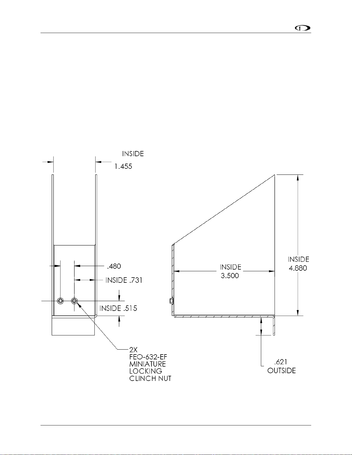
Autopilot Installation and Configuration
MOUNTING BRACKET DIMENSIONS
The dimensions for the included mounting bracket are below. This bracket will work with
varying panel thicknesses in both vertical and horizontal orientations. The primary force used to
secure the instrument to a panel is the “sandwich” action of tightening the bracket behind
through to the instrument bezel in front. The bracket includes a small mounting flange that can
be used to positively secure the bracket to the panel if desired. While not required for secure
mounting (the mounting screw clamps the panel between the bezel and bracket), securing the
bracket to the panel can make removal of the instrument easier by preventing the bracket from
falling behind the panel when removed. If you wish to use the mounting flange, simply match
drill it and rivet or bolt it in the desired spot. See the following section for details on where to
locate the bracket with respect to the hole in the panel. This flange can be trimmed if it is not
needed or if it interferes with other instruments.
8-12 FlightDEK-D180 Installation Guide
Page 97
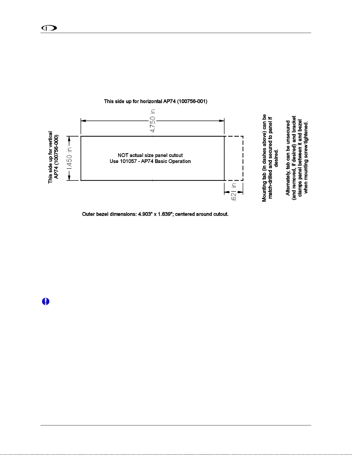
Autopilot Installation and Configuration
AP74 MOUNTING
As shown in diagram below, make a rectangular cutout (oriented either vertically or horizontally,
depending on instrument version ordered) of 1.45” by 4.75” (3.69 cm by 12.07 cm). Your AP74
also shipped with a life-sized mounting template for making this cutout and locating the optional
mounting flange holes. If the flange is used, secure it to your panel in whatever way you desire.
Riveting it to the panel is ideal, but drilling holes for mounting screws and nuts also works.
Upon locating the mounting bracket behind your panel, slide the instrument into it. The tapered
mounting screw fits into one of the PEM nuts at the back of the mounting bracket. Use the
included 7/64” Allen wrench to secure the mounting screw into the bracket. As you screw the
mounting screw tighter, the unit will be pulled back into the panel until the bezel sits flush. If the
bracket is installed without the assistance of the mounting flange, it will also be drawn forward
into the back of the panel when tightened. Tighten until the flange and bracket are securely
fastened to the panel.
Firmware Upgrades Required For AP Functionality
Because servo and AP74 firmware is upgraded at the same time as the Bus Master EFIS,
servo and AP74 power must be ON when EFIS firmware is upgraded.
To use the Dynon Avionics AP, the EFIS and all other Dynon products in the DSAB network
must be running the same firmware version (currently 5.4). This includes EFIS, EMS (including
those configured as backup/slave units), HS34, AP74, servos, and the EDC-D10A compass.
EFIS, EMS, and HS34 products must be individually upgraded via their individual serial ports
connected to a PC and running the latest version of the Dynon Avionics Product Support
Program.
the DSAB Bus Master EFIS (as is the EDC-D10A). To ensure reliable operation, all Dynon
devices should be upgraded to the same version of firmware; mismatched versions of firmware
on different devices can cause unreliable operation.
Autopilot servos and the optional AP74 are upgraded as part of the upgrade of
FlightDEK-D180 Installation Guide 8-13
Page 98

Autopilot Installation and Configuration
Detailed instructions for performing firmware upgrades are contained in the “Help” function of
the Dynon Avionics Product Support Program which is available on the Dynon Avionics web
site at downloads.dynonavionics.com
.
If you are using a GPS connected to your Dynon EFIS and will be using GPS as an input
for the AP, please upgrade your GPS to the most current firmware available for it.
Dynon’s testing has revealed certain incompatibilities with older versions of GPS
firmware that are corrected with current GPS firmware. Procedures for GPS firmware
upgrades vary by manufacturer; consult your GPS manual for the firmware upgrade
procedure. Additionally, some GPS units must be configured with specific settings to
work properly with Dynon’s instruments. More detail on compatibility with, and settings
for various GPS units is available on the Dynon Avionics web site at
wiki.dynonavionics.com
AP Servo Configuration
This section guides the installer through all the steps necessary to install, configure, and tune the
Autopilot software on the EFIS/servo system. The AP operation functions dealt with here are
primarily focused on configuration and tuning. Pilots should consult the FlightDEK-D180 Pilot’s
User Guide for a comprehensive description of AP operation.
.
Note: Before proceeding, verify that power is ON for all EFIS, EMS, HS34, AP74 and servo(s).
Note: If your system has more than one Dynon EFIS (that communicates over DSAB), the
configuration of most AP functions can only be performed from the EFIS configured as the
DSAB Bus Master (see Network Concepts on page 7-1).
CONFIGURATION OVERVIEW
1. Configure DSAB (required to be performed on the ground)
2.
Servo Calibration & Initial Servo Test (required to be performed on the ground)
3.
Roll Servo Initial Setup (recommended to be performed on the ground)
4.
Pitch Servo Initial Setup (recommended to be performed on the ground)
5.
Disengage/CWS Button Configuration (recommended to be performed on the ground)
6.
Audio Alerts Configuration (recommended to be performed on the ground)
7.
Prepare for Flight Test (recommended to be performed on the ground)
8.
Roll Servo Flight Calibration (recommended to be performed in flight under safe
conditions)
9.
Pitch Servo Flight Calibration (recommended to be performed in flight under safe
conditions)
STEP 1 - CONFIGURE DSAB
This step sets up the DSAB network so that the EFIS can communicate with the servo(s),
optional AP74, and any other Dynon products on the DSAB network.
As a safety precaution, while the Configure DSAB procedure is being performed, AP
functionality is disabled.
On the EFIS, perform the following:
8-14 FlightDEK-D180 Installation Guide
Page 99

Autopilot Installation and Configuration
Enter the EFIS > SETUP > DSAB > CONFIGURATION menu.
ARE YOU SURE YOU WANT TO RE-CONFIGURE THE NETWORK?
Press YES
ARE ALL NETWORKED DEVICES POWERED ON?
Press CONFIGURE NOW
PLEASE WAIT DETECTING ALL NETWORK DEVICES
Wait up to 1 minute
(X) DEVICES FOUND NETWORK CONFIGURATION IS COMPLETE
Verify that this
expected devic
Press FINISH
displayed, showing active roles and status. Verify that STATUS (at bottom) shows ACTIVE.
Press DOWN▼ once for each device in the network. Verify that the STATUS for each
device shows ACTIVE.
updated to the same version of firmware as the Bus Master EFIS. If the instrument
displaying UPGRADE REQ is one or more of your servos and/or AP74 (most common
upgrade via the Bus Master EFIS, even if the EFIS
After the above verification, press BACK > EXIT
STEP 2 - SERVO CALIBRATION AND SERVO TEST
The Servo Calibration procedure identifies the orientation and range of motion of each servo.
The Servo Test procedure verifies that each servo is configured properly by moving the control
surfaces, and requiring the pilot to verify correct movement. Un
the EFIS does not display the AP status or operation interface.
shows the correct nu
es are powered on.
If the status displays UPGRADE REQ, that instrument must b
mber of devices. If not, check wiring and ensure that all
d be Press UP▲ > and then SEL► to select the STATUS menu. The Bus Master EFIS shoul
ly
your EFIS), you must perform the when these devices were purchased separately from
is already at version 5.4 firmware.
til this procedure is completed,
If Airspeed Color Thresholds have not been configured, Servo Calibration and Servo T
cannot proceed, and the EFIS displays an error message. To configu
Thresholds, see Configure Airspeed Color Thresholds on page 5-4.
re Airspeed Color
e
est
Note: Servo calibration (SERVO CAL) and servo test (SERVO TEST) is a combined procedure
when Servo Calibration is completed successfully, you are prompted to perform Servo Test.
After a successful servo calib
whenever desired.
Note: The following steps assume that two servos are installed to provide AP control of Pitch
and Roll functions. If only a Pitch or Roll servo
sections.
On the EFIS, perform the following:
Enter the SETUP > AP > SERVO CALIB menu.
FlightDEK-D180 Installation Guide 8-15
ration, the SERVO TEST procedure can be performed on its own
has been installed, skip the non-applicable
;
Page 100
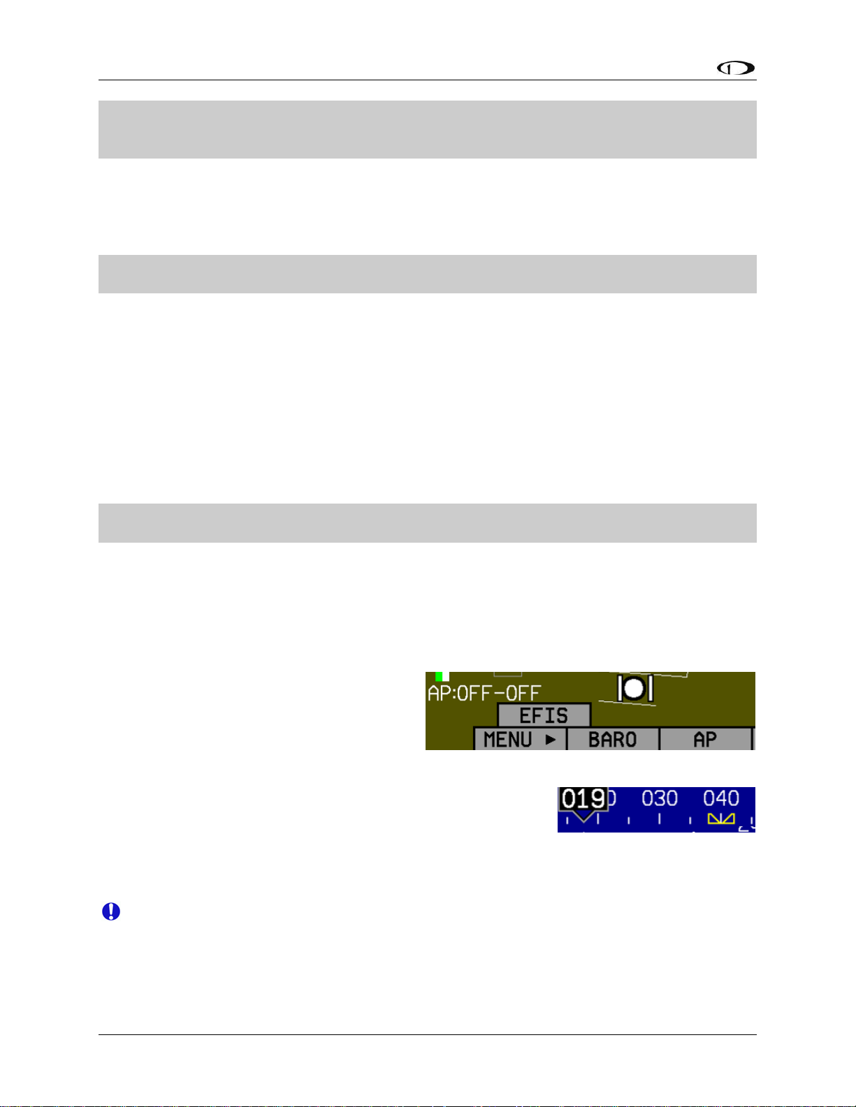
Autopilot Installation and Configuration
2 SERVO(S) FOUND PLEASE CENTER ALL CONTROL SURFACES AND MAKE SURE
THEY HAVE A FREE RANGE OF MOTION. PRESS DISCONNECT SWITCH TO
CONTINUE.
Follow all onscreen instructions, moving the controls to each position, pressing the
Disengage/CWS Button to confirm each position. This process calibrates the autopilot to
detect the orientation and range of each servo.
If calibration was successful:
CALIBRATION WAS SUCCESSFUL. ROLL FOUND. PITCH FOUND. PRESS OK BELOW
OR PRESS DISCONNECT SWITCH TO CONTINUE.
Press the AP Disengage/CWS Button or OK button on the EFIS.
If calibration was unsuccessful, an error message is displayed, describing the reason. The
most common causes are not enough travel being detected, or too much travel. In either case
mechanical adjustments must be made.
,
After successful completion of the calibration, the sys
TEST Mode. An initial SERVO TEST must be perfo
initial SERVO TEST is canceled, the AP status display at the lower left of the EFIS screen
shows “TST” as the status for the installed servo(s).
After successful calibration the screen displays:
PLEASE CENTER ALL CONTROL SURFACES AND MAKE SURE THEY HAVE A FREE
RANGE OF MOTION. PRESS OK BELOW TO BEGIN THE TEST.
Follow all onscreen instructions, moving the controls to each position, pressing the OK
button to confirm each position. This process verifies that the controls move to the correct
position, an
Note: After successful completion of Config
AP mode is
The AP status indicator is displayed at the
lower left of the EFIS screen (shown at
right).
The AP button is present on the EFIS
menu, replacing the BUGS menu (which
is now located within the AP menu).
All bugs (IAS, Heading, and A
ltitude) are turned hollow.
With an autopilot installed, the heading and altitude bugs are
only filled in when those modes
ALT hold).
The EFIS now has a record of which servo performs which function and the particular range
of motion it will be executing.
d ensures that the Disengage/CW
ure
enabled. The following occurs:
are engaged (HDG, TRK,
tem automatically continues into SERVO
rmed before the autopilot is usable. If the
S Button properly disengages the servos.
DSAB, Servo Calibration, and Servo Test, the
If servos are swapped or replaced, Servo Calibration must be performed again.
8-16 FlightDEK-D180 Installation Guide
 Loading...