


Bulletin D-58
Mark II Series Molded Plastic Manometers
Specifications - Installation and Operating Instructions
|
1-7/16 |
3-11/16 |
|
|
1-1/4 |
[35.53] |
[93.66] |
Ø7/32 [5.56] HOLE |
|
5/8 |
|
|
|
|
[31.75] |
|
|
|
|
[15.88] |
|
|
|
|
|
|
|
|
|
|
4-25/32 |
|
|
5-29/32 |
|
|
|
[150.02] |
|
|
[121.44] |
|
|
4-23/32 |
|
25/32 |
|
|
|
|
[19.84] |
|
|
[119.86] |
1-1/8 |
|
|
|
7/32 X 13/32 |
[28.58] |
|
25/32 [19.84] |
|
|
2-1/4 |
|
7-13/32 [188.12] |
[5.56 X 10.32] |
|
|
MOUNTING SLOT |
|||
[57.15] MAX |
|
|
|
|
|
|
|
|
|
Mark II Model No. 25 inclined-vertical manometer, (shown with optional A-612 portable stand)
Dwyer Mark II Manometers come in a variety of ranges. Make sure the fluid being used is for the correct manometer.
Mark II #25, 27, MM-80 and M-700 Pa use red gage fluid (specific gravity 0.826).
Mark II #26, 28 and MM180 use blue gage fluid (specific gravity 1.9).
If additional fluid is required, call, fax or email the Dwyer office listed at bottom of page.
INSTALLATION
Position manometer on a vertical surface. Drill two 1/8˝ or 9/64˝ holes on a vertical line 3-15/16˝ apart. Loosely mount manometer with self-tapping screws provided. Adjust gage until level bubble is centered in level vial, then secure the manometer tightly.
For portable use, order optional A-612 Portable Stand.
FILLING
Turn the zero set knob counterclockwise until it stops, then turn clockwise 3 full turns. This puts zero in approximately the middle of the travel adjustment in either direction. Remove the fill plug and fill with gage fluid until fluid reaches zero on scale. Minor adjustments can be made to adjust zero by adjusting zero knob. Replace fill plug. If gage is overfilled, remove excess by inserting pipe cleaner through the fill port to blot up excess fluid.
SPECIFICATIONS
Accuracy: ±3% FS.
Temperature Limits: 140°F (60°C).
Pressure Limits: 10 psi (70 kPa).
Weight: 1.04 lb (472 g).
MAINTENANCE
Check fluid level regularly and adjust zero with zero adjust knob. Be sure tubing connections are disconnected and gage is open to atmosphere before adjusting zero.
Clean with mild soap and water. Avoid any cleaning fluids which may result in damaging the gage.
ACCESSORIES
Each Mark II manometer includes two tubing connectors for 1/8˝ pipe or sheet metal ducts, two mounting screws, 1 oz. bottle of indicating fluid, red and green pointer flags, 8´ of double column tubing and instructions.
Model |
Range |
Fluid Used |
Mark II 25 |
0-3 in w.c |
Red fluid, .826 s.g. |
Mark II 26 |
0-7 in w.c. |
Blue oil, 1.91 s.g. |
Mark II 27* |
0-7000 fpm |
Red fluid, .826 s.g. |
Mark II MM-80 |
0-80 mm w.c. |
Red fluid, .826 s.g. |
Mark II M-700PA |
10-0-700 Pa |
Red fluid, .826 s.g. |
DWYER INSTRUMENTS, INC. |
|
Phone: 219/879-8000 |
www.dwyer-inst.com |
|
|||
P.O. BOX 373 • MICHIGAN CITY, INDIANA 46360, U.S.A. |
|
Fax: 219/872-9057 |
e-mail: info@dwyer-inst.com |
|
|
|
|
|
|
|
|
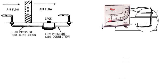
APPLICATIONS
AIR FILTER GAGE
Mount gage within 3 ft. of filter bank. Install tubing adapters on each side of filter. Run tubing from clean side of filter to positive pressure side of gage (left fitting). Run downstream side to low pressure side of gage (right fitting). Install green and red arrows adjacent to indicating tube to indicate filter condition.
AIR VELOCITY METER
A pitot tube should be used for air velocity readings. Install the pitot tube and gage carefully to ensure accuracy. Select a location for the pitot tube with al least four diameters of smooth straight sections of duct both upstream and downstream. Install pitot tube in the center of duct with tip directed into air stream. Connect the right angle (leg parallel to tip) to negative (right fitting) and straight pitot tube connection to positive (left connection) of gage. The velocity reading shown on the gage is the center or maximum velocity. For average velocity across the full area, multiply by a factor of 0.9.
No’s. 27 and 28 require pitot tube at additional cost. See Bulletin F-41-F.
The velocity indicated is for dry air at 70°F, 29.9˝ barometric pressure and a resulting density of 0.075 lb/ft3. For variation from these standard conditions, corrections may be based upon the following data.
MARK II MANOMETER
PITOT TUBE (SECTION ENLARGED TO SHOW DETAIL)
Pt Ps
PITOT TUBE SENSES TOTAL AND STATIC PRESSURES. MANOMETER MEASURES VELOCITY PRESSURE-(DIFFERENCE BETWEEN TOTAL AND STATIC PRESSURES).
AIR VELOCITY CALCULATIONS:
Air Velocity = 1096.2 √ PV
PV
D
where Pv = velocity pressure in inches of water D = Air density in lb/ft3
PB
Air Density = 1.325 x T
where PB = Barometric Pressure in inches of mercury
T = Absolute Temperature (indicated temperature °F plus 460)
Flow in cu. ft. per min. = Duct area in square feet x air velocity in ft. per min.
 Loading...