


 867
867
Spezialnähmaschine
Betriebsanleitung |
D |
Instruction manual |
|
|
|
GB |
|
Instructions d’emploi |
|
|
|
F |
|
|
|
Postfach 17 03 51, D-33703 Bielefeld • |
Potsdamer Straße 190, D-33719 Bielefeld |
|
||
Telefon +49 (0) 521 / 9 25-00 • Telefax +49 (0) 521 / 9 25 24 35 • www.duerkopp-adler.com |
||||
|
|
|
|
|
Ausgabe / Edition: |
Änderungsindex |
|
|
Teile-Nr./Part.-No.: |
04/2010 |
Rev. index: 05.0 |
|
Printed in Federal Republic of Germany |
0791 867740 |
|
|
|
|
|

Alle Rechte vorbehalten.
Eigentum der Dürkopp Adler AG und urheberrechtlich geschützt. Jede, auch auszugsweise Wiederverwendung dieser Inhalte ist ohne vorheriges schriftliches Einverständnis der Dürkopp Adler AG verboten.
All rights reserved.
Property of Dürkopp Adler AG and copyrighted. Reproduction or publication of the content in any manner, even in extracts, without prior written permission of Dürkopp Adler AG, is prohibited.
Tous droits réservés.
Propriété de la société Dürkopp Adler AG et protégé par la loi sur le droit d’auteur. Une copie ou reproduction par quelque procédé que ce soit du contenu sans accord écrite de l’auteur est interdite.
Copyright © Dürkopp Adler AG - 2010
Foreword
This instruction manual is intended to help the user to become familiar with the machine and take advantage of its application possibilities in accordance with the recommendations.
The instruction manual contains important information on how to operate the machine securely, properly and economically. Observation of the instructions eliminates danger, reduces costs for repair and down-times, and increases the reliability and life of the machine.
The instruction manual is intended to complement existing national accident prevention and environment protection regulations.
The instruction manual must always be available at the machine/sewing unit.
The instruction manual must be read and applied by any person that is authorized to work on the machine/sewing unit. This means:
–Operation, including equipping, troubleshooting during the work cycle, removing of fabric waste,
–Service (maintenance, inspection, repair) and/or
–Transport.
The user also has to assure that only authorized personnel work on the machine.
The user is obliged to check the machine at least once per shift for apparent damages and to immediatly report any changes (including the performance in service), which impair the safety.
The user company must ensure that the machine is only operated in perfect working order.
Never remove or disable any safety devices.
If safety devices need to be removed for equipping, repairing or maintaining, the safety devices must be remounted directly after completion of the maintenance and repair work.
Unauthorized modification of the machine rules out liability of the manufacturer for damage resulting from this.
Observe all safety and danger recommendations on the machine/unit! The yellow-and-black striped surfaces designate permanend danger areas, eg danger of squashing, cutting, shearing or collision.
Besides the recommendations in this instruction manual also observe the general safety and accident prevention regulations!

General safety instructions
The non-observance of the following safety instructions can cause bodily injuries or damages to the machine.
1.The machine must only be commissioned in full knowledge of the instruction book and operated by persons with appropriate training.
2.Before putting into service also read the safety rules and instructions of the motor supplier.
3.The machine must be used only for the purpose intended. Use of the machine without the safety devices is not permitted. Observe all the relevant safety regulations.
4.When gauge parts are exchanged (e.g. needle, presser foot, needle plate, feed dog and bobbin) when threading, when the workplace is left, and during service work, the machine must be disconnected from the mains by switching off the master switch or disconnecting the mains plug.
5.Daily servicing work must be carried out only by appropriately trained persons.
6.Repairs, conversion and special maintenance work must only be carried out by technicians or persons with appropriate training.
7.For service or repair work on pneumatic systems, disconnect the machine from the compressed air supply system (max. 7-10 bar). Before disconnecting, reduce the pressure of the maintenance unit. Exceptions to this are only adjustments and functions checks made by appropriately trained technicians.
8.Work on the electrical equipment must be carried out only by electricians or appropriately trained persons.
9.Work on parts and systems under electric current is not permitted, except as specified in regulations DIN VDE 0105.
10.Conversion or changes to the machine must be authorized by us and made only in adherence to all safety regulations.
11.For repairs, only replacement parts approved by us must be used.
12.Commissioning of the sewing head is prohibited until such time as the entire sewing unit is found to comply with EC directives.
13.The line cord should be equipped with a country-specific mains plug. This work must be carried out by appropriately trained technicians (see paragraph 8).
It is absolutely necessary to respect the safety instructions marked by these signs.
Danger of bodily injuries !
Please note also the general safety instructions.
Contents |
Page: |
Part 2: Installation Instructions Class 867 – Original Instructions
1. |
Scope of Delivery . . . . . . . . . . . . . . . . . . . . . . . . . . . . . . . . . . . . . . . . . . . . |
5 |
2. |
General and transport packing . . . . . . . . . . . . . . . . . . . . . . . . . . . . . . . . . . . |
5 |
3.Assembling the stand
3.1 |
Assembling the stand components (Standard). . . . . . . . . . . . . . . . . . . . . . . . . . . . |
7 |
3.2 |
Assembling the table plate . . . . . . . . . . . . . . . . . . . . . . . . . . . . . . . . . . . . . . . |
7 |
3.3 |
Assembling the stand components (Long arm) . . . . . . . . . . . . . . . . . . . . . . . . . . . |
9 |
3.4 |
Assembling the table plate . . . . . . . . . . . . . . . . . . . . . . . . . . . . . . . . . . . . . . . |
9 |
3.5 |
Self-manufacture of the table top . . . . . . . . . . . . . . . . . . . . . . . . . . . . . . . . . . . |
9 |
3.6 |
Setting the working height . . . . . . . . . . . . . . . . . . . . . . . . . . . . . . . . . . . . . . . . |
10 |
4.Sewing drives
4.1 |
Drive category, type and use . . . . . . . . . . . . . . . . . . . . . . . . . . . . . . . . . . . . . . |
11 |
|
|
4.2 |
Drive-pack components . . . . . . . . . . . . . . . . . . . . . . . . . . . . . . . . . . . . . . . . . |
12 |
|
|
4.3 |
Fitting the sewing drive. . . . . . . . . . . . . . . . . . . . . . . . . . . . . . . . . . . . . . . . . . |
12 |
|
|
4.4 |
Fitting the pedal |
12 |
|
|
GB |
||||
4.5 |
Fitting the sewing-drive control for machines with direct drive . . . . . . . . . . . . . . . . . |
13 |
||
4.6 |
Fitting the set value initiator |
13 |
|
|
|
||||
4.7 |
Fitting the pedal . . . . . . . . . . . . . . . . . . . . . . . . . . . . . . . . . . . . . . . . . . . . . . |
14 |
|
5.Assembling the machine head
5.1 |
Fitting the machine head . . . . . . . . . . . . . . . . . . . . . . . . . . . . . . . . . . . . . . . . . |
15 |
5.2 |
Fitting the oil suction tube . . . . . . . . . . . . . . . . . . . . . . . . . . . . . . . . . . . . . . . |
15 |
5.3 |
Fitting and tensioning the V-belt . . . . . . . . . . . . . . . . . . . . . . . . . . . . . . . . . . . . |
17 |
5.4 |
Attaching the knee lever . . . . . . . . . . . . . . . . . . . . . . . . . . . . . . . . . . . . . . . . . |
18 |
5.5 |
Fitting the operating panel. . . . . . . . . . . . . . . . . . . . . . . . . . . . . . . . . . . . . . . . |
19 |
5.6 |
Fitting the sewing lamp (optional equipment) . . . . . . . . . . . . . . . . . . . . . . . . . . . . |
19 |
6.Electrical connection
6.1 |
General . . . . . . . . . . . . . . . . . . . . . . . . . . . . . . . . . . . . . . . . . . . . . . . . . . . |
21 |
6.2 |
Checking the mains voltage . . . . . . . . . . . . . . . . . . . . . . . . . . . . . . . . . . . . . . . |
21 |
6.3 |
Connecting the sewing drive . . . . . . . . . . . . . . . . . . . . . . . . . . . . . . . . . . . . . . |
21 |
6.3.1 |
Connecting the clutch motor . . . . . . . . . . . . . . . . . . . . . . . . . . . . . . . . . . . . . . |
21 |
6.3.2 |
Connecting the coupling-positioning actuator . . . . . . . . . . . . . . . . . . . . . . . . . . . . |
21 |
6.3.3 |
Connecting the direct-current positioning actuator . . . . . . . . . . . . . . . . . . . . . . . . . |
21 |
6.4 |
Earthing . . . . . . . . . . . . . . . . . . . . . . . . . . . . . . . . . . . . . . . . . . . . . . . . . . . |
22 |
6.5 |
Connecting the sewing drive to the mains . . . . . . . . . . . . . . . . . . . . . . . . . . . . . . |
23 |
6.6 |
Drive-control connection sockets . . . . . . . . . . . . . . . . . . . . . . . . . . . . . . . . . . . |
23 |
6.7 |
Fitting the proximity switch . . . . . . . . . . . . . . . . . . . . . . . . . . . . . . . . . . . . . . . |
24 |
6.8 |
Connecting the machine head . . . . . . . . . . . . . . . . . . . . . . . . . . . . . . . . . . . . . |
24 |
Contents |
Page: |
6.9 |
Direction of rotation of sewing drive . . . . . . . . . . . . . . . . . . . . . . . . . . . . . . . . . . |
25 |
6.9.1Checking the direction of rotation with the coupling-positioning
actuator (mounted under the table) . . . . . . . . . . . . . . . . . . . . . . . . . . . . . . . . . . |
25 |
6.9.2Changing the direction of rotation with the coupling-positioning
|
actuator (mounted under the table) . . . . . . . . . . . . . . . . . . . . . . . . . . . . . . . . . . |
25 |
6.10 |
Connecting the sewing light transformer (optional equipment) . . . . . . . . . . . . . . . . . . |
26 |
6.10.1 |
Attaching and connecting the sewing light transformer (optional equipment) . . . . . . . . . |
26 |
6.10.2 |
Connection to the DA321G . . . . . . . . . . . . . . . . . . . . . . . . . . . . . . . . . . . . . . . |
27 |
6.11 |
Connecting the direct drive . . . . . . . . . . . . . . . . . . . . . . . . . . . . . . . . . . . . . . . |
28 |
6.11.1 |
Connecting the Hall sensor (optional equipment) . . . . . . . . . . . . . . . . . . . . . . . . . . |
28 |
6.11.2 |
Connecting the DA321G control unit . . . . . . . . . . . . . . . . . . . . . . . . . . . . . . . . . |
30 |
6.12 |
Connecting the knee switch . . . . . . . . . . . . . . . . . . . . . . . . . . . . . . . . . . . . . . . |
31 |
6.13 |
Mounting the M-Control PCB . . . . . . . . . . . . . . . . . . . . . . . . . . . . . . . . . . . . . . |
32 |
6.14 |
Setting the switches on the M-Control PCB . . . . . . . . . . . . . . . . . . . . . . . . . . . . . |
33 |
6.15 |
Setting machine-specific parameters . . . . . . . . . . . . . . . . . . . . . . . . . . . . . . . . . |
35 |
6.15.1 |
General . . . . . . . . . . . . . . . . . . . . . . . . . . . . . . . . . . . . . . . . . . . . . . . . . . . |
35 |
6.15.2 |
Autoselect . . . . . . . . . . . . . . . . . . . . . . . . . . . . . . . . . . . . . . . . . . . . . . . . . |
35 |
7.Pneumatic connection
7.1 |
Pneumatic sewing foot lifting . . . . . . . . . . . . . . . . . . . . . . . . . . . . . . . . . . . . . . |
35 |
8. |
Lubrication. . . . . . . . . . . . . . . . . . . . . . . . . . . . . . . . . . . . . . . . . . . . . . . . . |
36 |
9. |
Sewing test . . . . . . . . . . . . . . . . . . . . . . . . . . . . . . . . . . . . . . . . . . . . . . . . |
37 |
GB
3

9 |
10 |
1 |
2 |
|
|||
|
|
12
3
4
8
11
7
5
6
4

1.Scope of Delivery
What items are supplied depends on your order.
Prior to setting up, please check that all the required parts are present.
This description refers to a special sewing machine, of which all individual components can completely be delivered by Dürkopp Adler AG.
–1 Machine head incl. oil sump
Dürkopp Adler accessory set with:
–2 Reel stand
Protection cover (not represented)
–11 Oil tray
Set of electronic parts, depending on the order, for:
Machines with direct-current actuator
–4 Sewing-drive control
–10 Operating panel
–12 Cover
Machines with positioning actuators |
GB |
|
|
|
|
–Main switch
–Sewing-drive
–Synchronizer
–Belt guard
Optional equipment
–7 Stand (option)
–6 Pedal and pedal linkage (option)
–3 Table top (option)
–8 Drawer (option)
–Knee lever
–Pneumatic sewing foot lifting
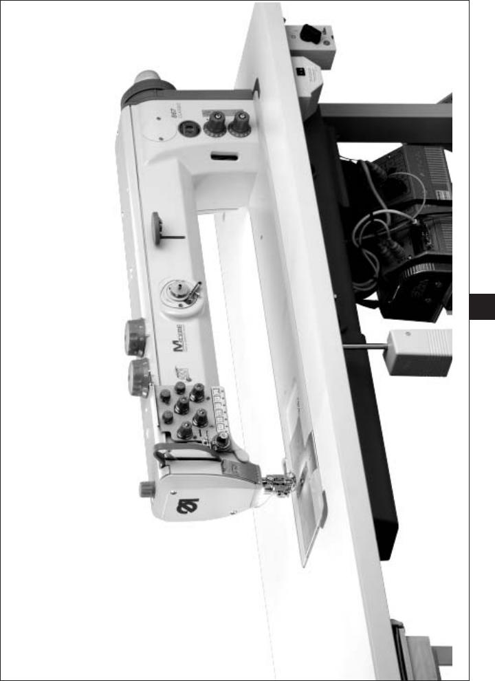
2.General and transport packing
Caution:
The special sewing machine must be set up by trained specialist personnel.
If the special sewing machine you have bought is already set up, the following transport packing must be removed:
–Safety straps and battens on the machine head, table and stand.
–Safety block and straps on the sewing drive
5
Observe the punch-marks of the table plate!
1
13
4,5x15 (x 4)
|
2 |
|
12 |
|
3 |
|
14 |
11 |
4 |
|
|
|
5 |
3,5x17 (x 6) |
6 |
|
10
3,9x15 (x 5)
3,5x17 (x 2)
7
9
B8x35 (x 4)
8
DIRECT DRIVE
6
3.Assembling the stand
3.1Assembling the stand components
–Assemble the individual stand components as shown in the illustration.
–Adjust the set screws 8 to insure the stability of the stand.
Make sure that the stand is safe by insuring that every single foot of the stand touches the ground.
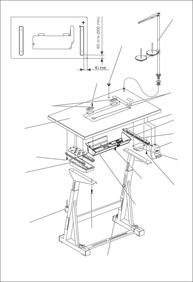
3.2Assembling the table plate
(867-190020, 867-190040, 867-190122, 867-190142, 867-190145, 867-290020, 867-290040, 867-190322, 867-190342, 867-190445, 867-290322, 867-290342, 867-290445, 867-392342, 867-393342, 867-490322)
In order to have an optimal arrangement of the components, follow the layout.
Stand |
Layout |
|
|
MG55 400304 |
0791 867710 |
MG55 400314 |
0791 867711 |
|
|
–Screw the drawer 10 with its holders onto the left side underneath the table plate.
–Screw the oil sump 7 under the table plate.
With sewing machine equipped with direct drive, all the three stops should lie against the table opening.
With sewing machine equipped with the drive mounted under the table,
|
the stop 14 must have 9 mm distance from the table top opening. |
GB |
|
– |
Screw the main switch 5* to the right side under the table plate. |
||
|
|||
– |
Screw the cable duct 4* behind the main switch 5 under the table |
|
|
|
plate. |
|
|
– |
Screw the holder 3 for the traction relief of the connecting cable |
|
|
|
behind cable duct 4 under the table plate. |
|
|
– |
Screw the sewing-lamp transformer 6 (optional equipment) |
|
|
|
under the table plate. |
|
|
– |
Put the cap 13 into the bore hole of the table plate. |
|
|
– |
Place the hinge bottoms 12 for the machine head into the cutout |
|
|
|
of the table plate 9 and tighten the screws. |
|
|
– |
Insert the rubber corner 2. |
|
|
– |
Attach the table plate 11 to the stand with woodscrews (B8 x 35) |
|
|
|
(see sketch for position). |
|
|
– |
Insert the yarn stand 1 in the hole in the table plate and secure it with |
|
|
|
the nuts and washers. Fit and align the yarn reel and unwinding holders. |
|
|
|
The yarn reel holder and the unwinding arm must be vertically in line. |
|
|
– |
Screw the holder for the oil-can 9 onto the left-hand stand brace. |
|
* Not applicable with sewing machines with direct drive.
|
9 mm |
oil sump |
table plate |
DRIVE UNDER THE TABLE |
|
7

MG58 400414 |
1 |
|
|
|
5 |
|
12 |
|
2 |
MG58 400404 |
4,5x15 (x 6) |
11 |
4 |
|
3,5x17 (x 2) |
|
6 |
|
3,9x15 (x 11) |
|
7 |
3,5x17 (x 6) |
|
10 |
|
9 |
|
|
B8x35 (x 4) |
8 |
|
8 |
|
3.3Assembling the stand components (Long arm)
–Assemble the individual stand components as shown in the illustration.
–Adjust the set screws 8 to insure the stability of the stand.
Make sure that the stand is safe by insuring that every single foot of the stand touches the ground.
3.4Assembling the table plate
(867-190040-70, 867-190342-70*, 867-290040-70, 867-392242-70*)
In order to have an optimal arrangement of the components, please follow the layout.
Stand |
Layout |
|
|
MG58 400414 |
0791 867716 |
MG58 400404 |
0791 867715 |
|
|
–Screw the drawer 10 with its holders onto the left side underneath the table plate.
–Screw the oil sump 7 under the table plate.
–Put the cap 5 into the bore hole of the table plate.
–Screw the cable duct 4 under the table plate.
– |
Place the hinge bottoms 12 for the machine head into the cutout |
GB |
|
||
|
of the table plate and tighten the screws. |
|
–Insert the rubber corner 2.
–Attach the table plate 11 to the stand with woodscrews (see sketch for position).
–Insert the reel stand 1 in the hole in the table plate and secure it with the nuts and washers.
Fit and align the yarn-reel and unwinding holders.
The yarn-reel holder and the unwinding arm must be vertically in line.
–Screw the holder for the oil-can 9 onto the left-hand stand brace.
*MG58 400414 only available for the above-quoted underclass.
Not applicable with sewing machines with direct drive.
3.5Self-manufacture of the table top
If you manufacture the table top yourself, please take the measurements from the illustrations on pages 40 and 41.
9
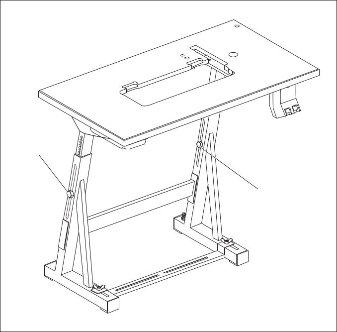
3.6Setting the working height
1 |
1 |
–The working height is adjustable between 750 and 900 mm (measured to the upper edge of the table plate).
–Undo screws 1 on the stand braces.
–Adjust the table plate horizontally to the required working height. To prevent tilting, pull the table plate out or push it in by the same distance on both sides.
–Tighten both screws 1.
10
 Loading...