


Duravit 760143, 760402, 760330, 760362, 760363 Pre-installation Data Sheet
...Leben im Bad
Living bathrooms
Pre-installation Data Sheet |
Bathtubs and Whirltubs |

Index |
|
Notes |
|
|
|
Notes........................................................................................................... |
2 |
Pre-installation............................................................................................ |
3 |
Maintenance openings................................................................................. |
5 |
Data sheets for bathtubs and whirltubs....................................................... |
9 |
PLANNING
Before starting the installation, plan the layout in detail, taking the site conditions into consideration.
TARGET READERSHIP AND QUALIFICATIONS
All work associated with the installation and water connection may only be undertaken by a plumber and all work associated with the electrical installation may only be undertaken by a licensed electrician.
SAFETY INSTRUCTIONS
Incorrect handling/transport may result in product damage.
The metal frame and whirl system are not resilient. >> Never hold by the metal frame or whirl system.
Improper transport can cause damage to the product and/or property damage, e.g. leaks.
>>Wear appropriate protective clothing.
>>Avoid knocks.
Risk of product and/or property damage!
The breach of local and country-specific regulations and standards can cause damage to the product and/or property damage.
>>Observe the local installation regulations and any country-specific standards at all times.
Duravit AG assumes no liability for the consequences of improper handling or improper transport.
2 Pre-installation data sheet

Pre-installation
INSTALLATION LOCATION / INSTALLATION ROOM
>> Make sure that the installation location fulfils the following criteria
Doors / external |
• |
Ensure that doors or other access openings are |
access |
|
large enough to accommodate transport dimen- |
|
|
sions, keeping in mind the weight and need for |
|
|
sufficient manoeuvring room. |
|
|
|
Required area |
• |
Allow for enough space around the tub for the in- |
|
|
stallation. |
|
|
|
Floor |
• |
Completely level. |
|
• |
At a right angle to the wall. |
|
• |
Note the overall strength of the floor structure |
|
|
including the floor finish. |
|
• |
There must not be any underfloor heating under |
|
|
the tub. |
|
• |
Install tubs after the tiles. (Top edge of finished |
|
|
floor). |
|
• |
Depending on the combination of tub and whirl |
|
|
system it is possible that system components may |
|
|
protrude beyond the edge of the tub. We there- |
|
|
fore recommend installation in a support frame. |
|
• |
Tolerances for acrylic: As a result of the manu- |
|
|
facturing process, deviations from the nominal |
|
|
dimensions may occur within the limits specified |
|
|
in the DIN 198 standard. Please take this into |
|
|
account in your planning. |
|
|
|
Wall |
• |
Tiled. |
|
• |
At a right angle to the tub. |
|
• |
Completely straight. |
|
• |
Note the overall strength of the wall structure |
|
|
including the wall finish. |
|
|
|
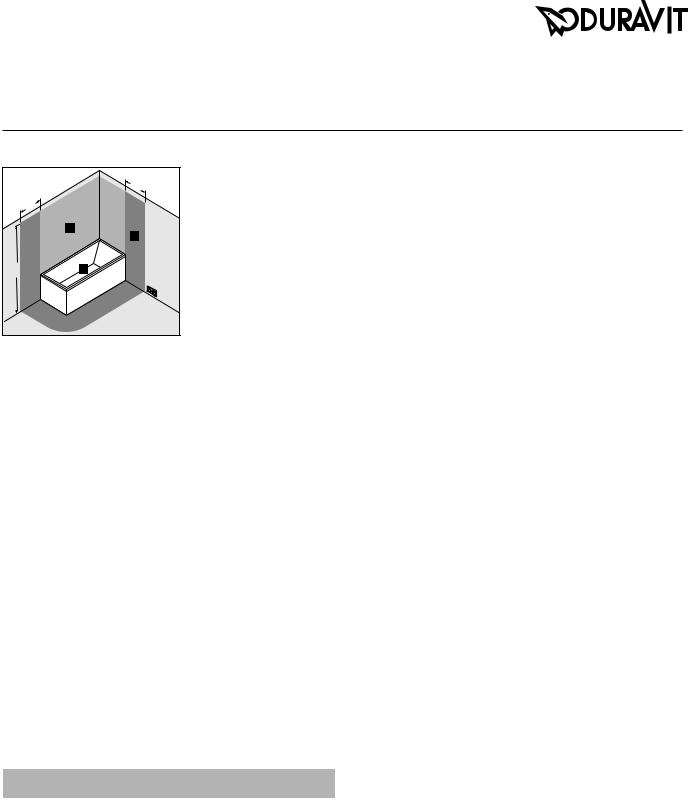
WATER INSTALLATION
NOTE
A pipe interrupter is absolutely essential for tubs with a base inlet (DIN EN 1717).
> Comply with assembly scheme.
| <![if ! IE]> <![endif]>> = 150 |
Water connection
•Connections for the water supply and drains must be in compliance with the currently valid standards and public regulations.
•Position the water drain (DN 50) flush to the mounting surface or out of
the wall directly above the mounting surface; see drawing for recommended area.
MAINTENANCE OPENINGS AND AIR SUPPLY
NOTE
It is recommended to install the tub with a removable bathtub panel due to the improved maintenance options.
Tiling the tub
The following maintenance openings must be provided:
• Cable-driven waste and overflow |
200 x 200 mm |
|
• |
Units |
500 x 500 mm |
|
(Please see the section on “Maintenance openings”) |
|
• |
Control unit for coloured LED light |
200 x 200 mm |
|
(Maintenance opening at the foot end) |
|
•Provide an opening in the panel for the air supply with an effective area of approx. 15 cm2 (e.g. 3 x 5 cm or 2 x 7.5 cm).
Tub with a panel
•The panel must be removed for maintenance, and with a seamless panel, the tub must be removed from the wall. Your plans should therefore include a clearance in front of the tub.
•The air supply for the whirl system (ventilation grille/ventilation slot) must not be covered.
ELECTRICAL INSTALLATION
 DANGER Risk of fatal electric shock
>>Disconnect the power supply while working on the electrical components.
>>The device must be earthed. Earthed appliances must be permanently connected to fixed wiring.
>>Connect the device only to the designated electrical cable.
>>NEVER touch the power supply line with wet hands.
Pre-installation
>>Lay a permanent power supply line which must be on a separate circuit.
•The device itself does not have electrical leakage protection function. The device must be supplied through a residual current device (RCD) with a rated residual operating current not exceeding 30 mA.
•Means for disconnection must be incorporated in the fixed wiring in accordance with the wiring rules and have a contact separation in all poles that provides full disconnection under overvoltage category III conditions outside the prescribed protection zones (0 – 2).
•Leave 3000 mm of the supply line exposed.
>>Lay an equipotential bonding cable:
•Leave 3000 mm of cable exposed.
>>Select a supply line cross-section based on the connected load on the identification plate (2.5 mm – 4 mm).
>>Confirm that the grounding wire is 10 mm (⅜ ”) longer than the L and N wire.
>>Install a circuit breaker.
Pre-installation data sheet 3
PROTECTION ZONES
|
600 |
|
600 |
|
1 |
|
2 |
| <![if ! IE]> <![endif]>2250* |
0 |
|
* Or the height of the highest fixed-location shower head/water outlet, whichever is higher.
Combi-System L |
1.59 kW |
2.64 kW |
(# 760XXX XX X CL 10XX) |
|
|
Jet System E |
1.14 kW |
2.20 kW |
(# 760XXX XX X JE 10XX) |
|
|
Power supply |
|
|
# 76XXXX XX X XX XXX0: |
220 – 240 V AC, 50 Hz |
|
# 76XXXX XX X XX XXX6: |
220 – 240 V AC, 60 Hz |
|
Fuse |
IN = 16 A |
|
RCD |
IΔN ≤ 30 mA |
|
COLOURED LED LIGHT/WHITE LED LIGHT UNDER THE EDGE OF THE TUB FOR BATHTUBS
Electrical data
Power supply
Coloured LED light with remote control |
110 – 240 V AC, 50/60 Hz, |
|
for bathtubs |
|
30 W |
#790840 00 0 00 xx00 |
|
|
|
|
|
Coloured LED light with remote control |
110 – 240 V AC, 50/60 Hz, |
|
for Blue Moon bathtub |
|
60 W |
#790846 00 0 00 xx00 |
|
|
|
|
|
White LED light under the edge of the |
220 – 240 V AC, 50/60 Hz, |
|
tub |
|
50 W |
#791847 00 0 00 0000 |
|
|
#791848 00 0 00 0000 |
|
|
#791849 00 0 00 0000 |
|
|
|
|
|
Fuse IN = 16 A |
|
|
RCD |
IΔN ≤ 30 mA |
|
WHIRLTUBS
Electrical data
Whirl system |
Rated power with |
Max. rated power, |
|
standard equipment |
fully-equipped |
Air System |
0.76 kW |
0.85 kW |
(# 760XXX XX X AS 00XX) |
|
|
Air System (DuraSolid) |
0.58 kW |
0.58 kW |
(# 760XXX XX X AS 00XX) |
|
|
Jet Project |
0.66 kW |
0.66 kW |
(# 760XXX XX X JP 10XX) |
|
|
Jet System |
0.59 kW |
0.67 kW |
(# 760XXX XX X JS 10XX) |
|
|
Combi-System P |
1.89 kW |
1.98 kW |
(# 760XXX XX X CP 10XX) |
|
|
Combi-System E |
1.91 kW |
2.96 kW |
(# 760XXX XX X CE 10XX) |
|
|
4 Pre-installation data sheet

Maintenance openings
Maintenance
Install the whirltub in such a way that all of the important equipment (pump, blower and control system) remains accessible. It is recommended to install the tub with a removable furniture panel for easy maintenance.
Blue Moon
Head |
Head |
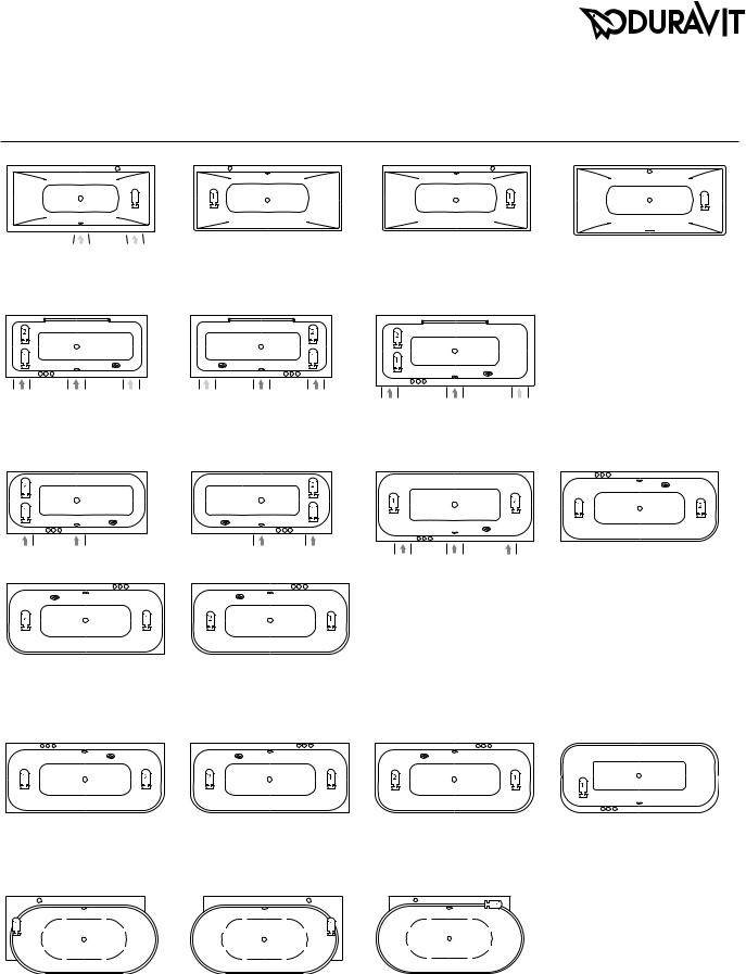
Location of the whirl system components
The illustrations show the standard configuration for the components of the whirl system* with the location of the operating unit. The back massage is located at the head end (depending on the whirl system).
Custom-made designs available on request. In such cases we will require a drawing showing the desired layout. Duravit will confirm whether the desired layout can be implemented.
# 760143 |
# 760402 |
Cape Cod |
|
| <![if ! IE]> <![endif]>Head |
<![if ! IE]> <![endif]>Head |
# 760330 |
# 760362 |
Darling New |
|
| <![if ! IE]> <![endif]>Head |
|
# 760242 |
# 760243 |
| <![if ! IE]> <![endif]>Head |
|
# 760246 |
# 760247 |
D-Code |
|
| <![if ! IE]> <![endif]>Head |
<![if ! IE]> <![endif]>Head |
|
HeadHead |
# 760363 |
# 760364 |
| <![if ! IE]> <![endif]>Head |
<![if ! IE]> <![endif]>Head |
|
# 760244, # 760245 |
|
Head Head |
|
# 760248 |
| <![if ! IE]> <![endif]>Head |
<![if ! IE]> <![endif]>Head |
# 760095, # 760096, |
# 760097, # 760099 |
# 760101 |
# 760137 |
# 760098, # 760100 |
|
|
|
| <![if ! IE]> <![endif]>Head |
|
|
|
# 760138
* Please note that depending on the combination of tub and whirl system it is possible that system components may protrude beyond the edge of the tub. We therefore recommend installation in a support frame
Pre-installation data sheet 5
DuraSquare
| <![if ! IE]> <![endif]>Head |
<![if ! IE]> <![endif]>Head |
|
# 760426 |
# 760427 |
# 760428, # 760429 |
DuraStyle |
|
|
| <![if ! IE]> <![endif]>Head |
<![if ! IE]> <![endif]>Head |
<![if ! IE]> <![endif]>Head |
# 760292, # 760294, # 760296 |
# 760293, # 760295, # 760297 |
# 760298, # 760299 |
Happy D.2 |
|
|
| <![if ! IE]> <![endif]>Head |
<![if ! IE]> <![endif]>Head |
<![if ! IE]> <![endif]>Head |
# 760308, # 760310, # 760312 |
# 760309, # 760311, # 760313 |
# 760314, # 760315 |
| <![if ! IE]> <![endif]>Head |
<![if ! IE]> <![endif]>Head |
|
# 760317 |
# 760318 |
|
Happy D.2 Plus |
|
|
| <![if ! IE]> <![endif]>Head |
<![if ! IE]> <![endif]>Head |
|
# 760449 |
# 760450 |
# 760451 |
Luv |
|
|
| <![if ! IE]> <![endif]>Head |
<![if ! IE]> <![endif]>Head |
<![if ! IE]> <![endif]>Head |
# 760431 |
# 760432 |
# 760433 |
| <![if ! IE]> <![endif]>Head |
<![if ! IE]> <![endif]>Head |
# 760430
<![if ! IE]><![endif]>Head
# 760316
HeadHead
# 760453
6 Pre-installation data sheet
 Loading...