

Page 1
WARRANTY
DuraT rax®guarantees this kit to be free from defects in both material and workmanship at the date of purchase.DuraTrax will
warranty this kit for 90 days after the purchase date. DuraTrax will repair or replace, at no charge, any incorrectly made part.
Make sure you save the receipt or invoice you were given when you bought your model! It is your proof of purchase
and we must see it before we can honor the warranty. Fur ther, DuraTrax reserves the right to change or modify this
warranty without notice.
To return your Overdrive ST for repairs covered under warranty you should send your truck to:
Hobby Services
1610 Interstate Drive
Champaign, Illinois 61822
Attn: Service Department
Phone: (217) 398-0007 9:00 am-5:00 pm Central Time M-F
E-mail: hobbyservices@hobbico.com
If the buyer is not prepared to accept the liability associated with the use of this product,the buyer is advised to
return this kit immediately in new and unused condition to the place of purchase .
© Copyright 2001 DTXZ1095 For Kit DTXD92**
ASSEMBLY AND OPERATION MANUAL
Length: 17-3/4" [450mm]
Width: 12-5/8" [320mm]
Height: 4-15/16" [125mm]
Weight: 5lbs 6oz
Wheelbase: 11-7/16" [290mm]
Radio: 2 channel surface frequency
Engine: Velocity .17
READ THROUGH THIS MANUAL BEFORE STARTING.
IT CONTAINS IMPORTANT INSTRUCTIONS AND
WARNINGS CONCERNING THE ASSEMBLY AND USE
OF THIS MODEL.
1610 Interstate Drive Champaign, IL 61822
(217) 398-8970, Ext. 2
carsupport@duratrax.com
TM
Page 2

Introduction.......................................................................2
Safety Precautions...........................................................2
Helpful Hints.....................................................................2
Stress-Tech Parts Guarantee ..........................................2
Repair Service ..................................................................2
Specification and Description Changes ........................3
Required Items for Completion.......................................3
Tools Needed for Completion .........................................3
Included T ools...................................................................3
Prepare the Radio System...............................................3
Finishing the Overdrive ST .............................................4
High Speed Needle...........................................................5
Low Speed Needle ...........................................................5
Throttle Stop Screw .........................................................5
Engine Break-in................................................................5
Starting the Engine ..........................................................6
How to Stop Your Engine .................................................6
Ensuring Engine Life .......................................................7
Glow Plugs ........................................................................7
Fuel....................................................................................7
Overheating ......................................................................7
Reversing T ransmission..................................................8
2-Speed Adjustments.......................................................8
Maintenance Tips..............................................................8
Tuning Guide ....................................................................9
Thank you for purchasing the DuraTrax Overdrive ST. This
manual contains the instructions you need to build, operate and
maintain your new nitro R/C truck. Read over this manual
thoroughly before building or operating the Overdrive ST.
When the safety precautions are followed, the Overdrive ST
will provide years of enjoyment.Use care and good sense at
all times when operating this radio-controlled truck. Failure
to use this vehicle in a safe, sensible manner can result in
injury or damage to property.You and you alone must insure
that the instructions are carefully followed and all safety
precautions are obeyed.
•
Do not operate the Overdrive ST near people.Spectators
should be behind the driver or at a safe distance away
from the vehicle.
•
Always turn on the transmitter before turning on
the Overdrive ST.
•
Before turning on your radio check to make sure that no
one else is running on the same frequency as your
Overdrive ST.
• Avoid w orking ov er a deep pile carpet.If you drop a small
part or screw, it will be difficult to find.
• Place a mat or towel over your work surf ace.This will prev ent
parts from rolling off and will protect the work surface.
• Avoid running the truck in cold weather. The plastic and
metal parts can become brittle at low temperatures. In
addition, grease and oil become thick, causing premature
wear and poor performance.
• Test fit all parts before attaching them permanently.
We hav e engineered the Overdriv e ST to take the rough and
tumble abuse that makes R/C stadium trucks fun.We are so
confident of the quality and durability of the Stress-Tech
plastic parts that we will replace any Stress-T ech plastic part
you break during the first 12 months you own the truck.Just
send in the part to us and we will send you a FREE
replacement. Please see the Overdrive ST parts list for the
items covered under the Stress-Tech guarantee.
To receive your free replacement part please send the
following to the Hobby Ser vices address listed on the cover
of this manual.
❏ 1. The broken par t must be included.
❏ 2. The part number and description of the broken part.
❏ 3. Dated copy of your invoice or purchase receipt.
❏ 4.Your name, phone number and shipping address.
Repair service is available anytime. After the 90 day
warranty, you can still have your Overdrive ST repaired for a
small charge by the experts at DuraTrax's authorized repair
facility, Hobby Services, at the address listed on the front
page of this manual.
To speed up the repair process, please follow the
instructions listed below.
❏ 1. Under most circumstances retur n the ENTIRE system:
truck and radio.The exception would be sending in a StressTech part. See the instructions under Stress-Tech Guarantee.
❏ 2. Make sure the transmitter is turned off, and all of the
batteries are removed.
REPAIR SERVICE
STRESS-TECH™PARTS GUARANTEE
HELPFUL HINTS
SAFETY PRECAUTIONS
INTRODUCTION
TABLE OF CONTENTS
2
Page 3
❏ 3. Send written instructions which include: a list of all
items returned, a THOROUGH explanation of the problem,
the service needed and your phone number during the day.
If you expect the repair to be covered under warranty, be
sure to include a proof of date of purchase (your store
receipt or purchase invoice).
❏ 4. Also be sure to include your full return address.
All pictures, descriptions and specifications found in this
instruction manual are subject to change without notice.
DuraTrax maintains no responsibility for inadvertent errors
in this manual.
The DuraTrax Nitro Starter Pack (DTXP0200) contains
fuel, fuel bottle, glow plug starter, glow plug wrench
and glow plug.
To operate the Overdrive ST the follo wing items are required:
❏ 1. Fuel (DuraTrax Red Alert
™
fuel-DTXP0520)
❏ 2. Extra Glow Plugs (DTXG3001)
❏ 3. Glow Plug Wrench (DTXR1170)
❏ 1. #2 Phillips head screwdriver (DTXR0124)
❏ 2. Flat blade screwdriver (DTXR0158)
❏ 3. Air Filter Oil (DTXC2465)
❏ 1. Turnbuckle wrench
❏ 2. Nut driver (4-way)
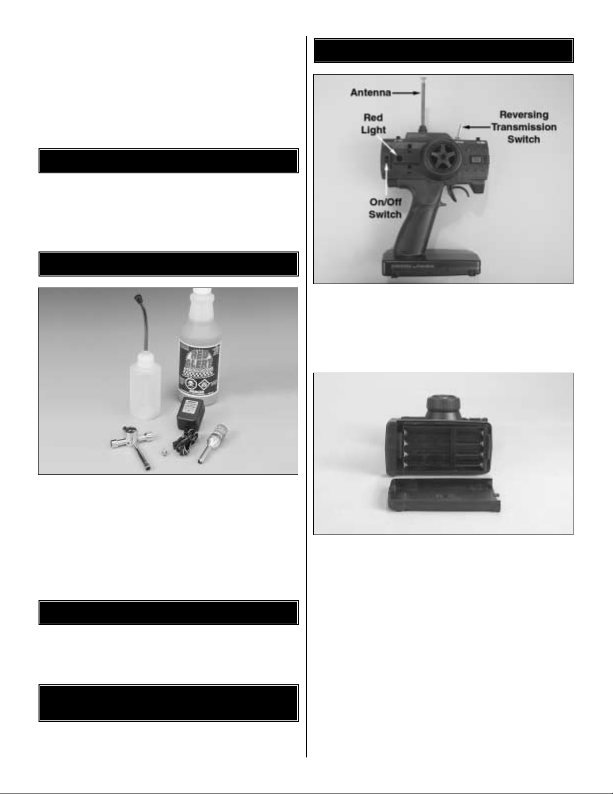
❏ 1. Install the transmitter antenna by screwing it into the
hole on the top of the transmitter.
❏ 2. Slide open the battery door on the bottom of the
transmitter. Place 8 “AA” batteries into the holder in the
configuration molded into the plastic on the battery holder.
Reinstall the battery door.
❏ 3. Turn on the transmitter using the switch on the side
(see photo step 1). The red light on the side of the
transmitter should light up. If there is no light on, tur n the
transmitter off and check to ensure that the batteries are
making contact with the metal contacts in the battery holder.
Make sure the batteries are installed correctly. Turn the
transmitter on and check for the red light. If the red light
appears, turn off the transmitter. If the red light blinks, the
batteries are low and should be replaced.
PREPARING THE RADIO SYSTEM
INCLUDED TOOLS FOR
MAINTENANCE AND TUNING
TOOLS NEEDED FOR COMPLETION
REQUIRED ITEMS FOR OPERATION
SPECIFICATION & DESCRIPTION CHANGES
3
Page 4
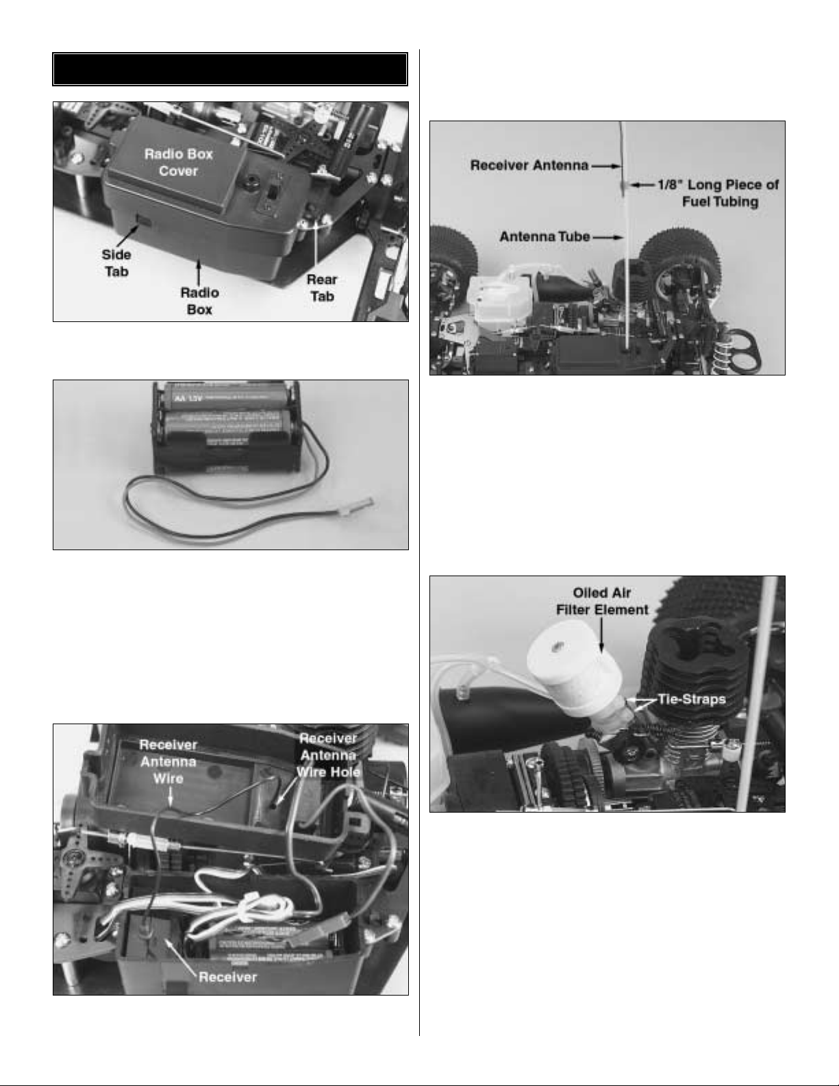
❏ 1. Remove the radio box cover by releasing the two
tabs shown.
❏ 2. Remove the 4 cell receiver battery box from the radio
box and install (4) “AA” included batteries into the batter y
holder. Follow the configuration molded into the battery
holder. Re-install the receiver battery holder back into the
radio box.Plug the connector on the receiver battery into the
socket on the receiver switch wire. The receiver battery
connector can only be plugged in one way. Tuck the wires
into the the groove in the radio box so that they do not get
crimped under the radio box cover.
❏ 3.Remove the twist-tie from the receiver antenna.Thread the
receiver antenna wire through the hole in the radio box cover.
❏ 4. Reinstall the radio box cover onto the receiver box.
Secure the radio box cover with the two tabs on the radio
box. Make sure the tabs lock into place.
❏ 5. Remove the antenna tube from the parts bag. Thread
the receiver antenna through the antenna tube.The antenna
will be longer than the antenna tube. Do not coil or cut the
receiver antenna. Press fit the antenna tube through the
hole in top of the radio box. Place a 1/8" long piece of fuel
tubing over the antenna tube and wire to secure in place.Tip:
Run the antenna through your fingers to straighten out
kinks before running through the antenna tube. Also,
applying a small amount of soapy water to the antenna
wire will allow the wire to slide through the tube easier.
❏ 6.Thoroughly soak the air filter foam with air filter oil (not
included) and then squeeze out the excess oil.DuraTrax Air
Filter Oil (DTXC2465) is available from your local hobby
dealer.Attach the adapter tube to the air filter base with one
of the included tie straps. Place the air filter onto the
carburetor and secure it in place with the other included tie
strap.Cut the excess part off of both straps. TIP: Shock oil
or a light machine oil may be substituted for air filter oil.
❏ 7. Remove the plastic protective cover from the outside
of the body. Apply decals if desired.Place the body onto the
body posts. Place an included body pin onto each of the
body posts to secure the body to the chassis.
FINISHING THE OVERDRIVE ST
4
Page 5

The “high-speed” needle is sticking up from the side of the
carb.It is located in the brass housing, just above the fuel inlet.
It controls the fuel to air mixture of the carb.The needle is preset for break-in from the factory at 2-3/4 turns out from the fully
closed position of the carb. Once the engine is broken-in,
the high-speed needle would typically run 2 to 2-1/2 turns out
from closed, depending on the weather, humidity and altitude
above sea level. To richen the mixture turn the needle
counterclockwise.To lean it turn the needle clockwise.
The engine is factory set. Adjustments may need to be
made to obtain optimum performance.
The “low-speed”needle is located on the side of the carburetor.
It controls the fuel to air mixture at low throttle settings.There is
a simple way of adjusting the low-speed needle correctly, called
the “pinch test.” With the engine at idle, pinch the fuel line and
listen to how the engine speeds up or slows down.If the engine
increases its speed for about 2 or 3 seconds and then loses
speed, the needle is set correctly. If the engine loses RPM
quickly, it is set too lean and the low-speed needle needs to be
opened (counterclockwise) to richen the mixture.Pinch again to
check the mixture.If the engine takes longer than 4 seconds to
slow down, lean (clockwise) the low-speed needle and then
pinch again to check the mixture.
On the front of the carburetor, there is a black screw.This is
called the idle stop screw. This increases or decreases the
idle RPM without changing the fuel to air mixture.The barrel
should be approximately 1.5mm (between 1/32" and 1/16")
from fully closed.
To insure long life and good performance from your Velocity
.17 engine, you MUST break-in the engine. The break-in
period is critical for long life of the internal parts of the
engine.This should be done over the first 4 or 5 tanks of fuel.
SOME THINGS TO REMEMBER DURING BREAK-IN:
❏ 1.Run with the body off.This will keep the engine cooler .
❏ 2. Keep the air cleaner on at ALL times
❏ 3. Run on a smooth, hard surface.An empty parking lot
is perfect.
❏ 4.Use the same fuel that you will use for normal running.
❏ 5. Resist the urge to accelerate and decelerate the
truck quickly.
❏ 6.Break-in puts stress on the glow plug and you can burn
it out during break-in. Make sure you have an extra plug or
two on hand.
❏ 7. Do NOT overheat the engine.You can check the head
temperature by using one of the temperature gauges that
are available or by putting a drop of water on the top of the
cylinder head. If the water boils away immediately, shut off
the engine and allow it to cool. If it takes more than 5
seconds to boil away, the engine is at proper running
temperature for break-in.
Before running the engine, read the manual and watch
the engine video that came with this kit.
ENGINE BREAK-IN
THROTTLE STOP SCREW
LOW-SPEED NEEDLE
HIGH-SPEED NEEDLE
5
Page 6

6
❏ 1. Install a glow plug. This threads into the top of the
cylinder head.
❏ 2. Fueling - Fill the tank almost to the top. Leave a little
air at the top of the tank.
❏ 3. Prime the engine - Use the primer button on the fuel
tank to force the fuel through the fuel line.Watch the fuel go
through the line and when it gets to the carburetor , press the
primer button once more to get fuel into the engine.
❏ 4. Open the high speed needle valve exactly 2-3/4 turns
out (counterclockwise) from fully closed. The high-speed
needle is sticking up from the carburetor inside the brass
housing.All of the carburetor settings are adjusted with a flat
bladed screwdriver.
❏ 5. Remove the battery door on the side of the glow
starter by squeezing the indicated tab. Install the included
"C" size battery with the negative end of the battery being
placed against the spring. Re-install the battery door back
onto the glow starter, making sure the tabs slide into place
and the door securely locks into place.
❏ 6.Secure the glow plug starter onto the engine’s glow plug.
❏ 7.Start the engine by pulling the recoil - Use short, quick
pulls. DO NOT pull the recoil starter's string to the end.You
only need 10 to 12 inches of pull to start the engine.
❏ 8.Your truck is equipped with a throttle return spring. It is
installed between the cylinder head and the throttle arm on
the carburetor. This will return the throttle to idle if there is a
loss in power for the on-board radio equipment.
Sometimes it is helpful to start the engine at around half
throttle.Have a friend pull back on the throttle some while you
start the engine. This may be an indicator that the low speed
needle setting needs to be adjusted.When the engine starts,
immediately return the throttle to idle. If this is not done the
engine can over-rev and cause engine damage. If the engine
is difficult to turn over with the recoil starter, especially if it is
brand new , loosen the glow plug a half turn before starting the
engine. This allows some compression to escape, but the
engine will still start. Make sure you tighten the glow plug after
the engine starts. If the recoil starter is still difficult to pull, the
engine is flooded - there is too much fuel inside the engine.
Remove the glow plug, then turn the engine upside down and
pull the recoil 5 or 6 times. This will clear the engine of fuel,
and you will notice the recoil pulls easier. Replace the glow
plug and repeat the starting procedure.
FUELS
Use fuels that are specially formulated for car and truck
engines. DuraTrax Red Alert (DTXP0520) fuel is specially
formulated for truck engines like the Velocity .17.
You may hav e been wondering how to stop the engine.All you
have to do is pinch the fuel line that runs to the carburetor
from the bottom of the fuel tank. Pinching this line will restr ict
the fuel flow and the engine will quit within a few seconds.
THE FIRST TANK
Your first tank of fuel should be running the truck at a very
rich high-speed needle valve setting.This allows the fuel to
carry as much oil as possible into the engine to lubricate the
internal parts dur ing the break-in.
❏ 1. Open the high speed needle valve 2-3/4 turns from
fully closed (counterclockwise). This is factory set already,
but check it to make sure. When closing the high-speed
needle, close the needle until you feel some resistance. DO
NOT over tighten or you will damage the engine.
❏ 2. Start the engine.
❏ 3. Once the engine is started, open the high-speed
needle valve around 1/8 turn at a time, finding the setting
where the engine just barely runs.This may take a few times
adjusting the needle, running the truck away from you and
back, then adjusting the needle. The truck will perform
sluggishly and stall from time to time - that is normal.
❏ 4. Run the truck
❏ 5. After a minute or two of running back and forth at
medium speeds, slowly accelerating and decelerating the
truck, make sure the engine is not overheating by putting a
drop of water on the cylinder head and watching it boil away.
If it boils away immediately, stop the engine and allow it to
cool. Open the high-speed needle around a 1/4 turn before
starting again.This is a good habit to get into every time you
run to ensure that the engine does not overheat during any
run. Looking at the smoke that comes out the exhaust is
also an indicator of how rich or lean the engine is running. If
there is a good amount of smoke coming out of the exhaust,
then chances are good that you are running rich.
❏ 6. Run the truck back and forth at a medium speed until
the tank is almost out of fuel.Do not allow the tank to run out
of fuel.This leans out the engine and can cause overheating
(See How To Stop Your Engine).
❏ 7. Stop the engine and allow the engine to cool before
the second tank.This normally takes around 10 minutes.
TANKS 2-5
Turn in the high speed needle valve (clockwise) around 1/12
turn from the previous setting. Run the truck back and forth.
You should notice that the truck will perform better during
each run. Stop the truck periodically to check for overheating.
If it is too hot, stop the engine.Wait for it to cool, then open up
the high speed needle valve and restart. After the 5th tank,
you should be near to the peak performance of the engine.
HOW TO STOP YOUR ENGINEST ARTING THE ENGINE
Page 7

7
10 Ways To Ensure A Long Life From Your Engine:
❏ 1.Keep your engine clean.Dirt will act as insulation on an
engine. It will not be able to shed heat as easily. Use a good
air filter to keep dirt out of your engine and clean it often.
❏ 2. Do not over-lean your engine.
❏ 3. Do not run your engine with little or no load. Don't
throttle up the engine to full throttle when the wheels are not
in contact with the ground.
❏ 4. Do not overheat the engine. This goes along with
keeping it clean and not over-leaning the engine.
❏ 5.Do not use a fuel with a low oil content. Make sure you
use a fuel from a reputable manufacturer, such as DuraTrax
Red Alert.
❏ 6. Avoid using old fuels in the engine. Always run all of
the fuel out of the engine. After running for the day, use an
after-run oil and work it into the engine by turning the
flywheel or pulling the engine recoil slowly.
❏ 7. Do not use a fuel with a nitromethane (often called
nitro) content over 20%.
❏ 8. Do not scratch the piston or cylinder sleeve. Avoid
jamming something into the exhaust port when removing or
reinstalling the clutch or flywheel. Use a special tool called a
crankshaft locking tool, which is installed in the glow plug hole.
❏ 9. Do not use silicone sealer on the engine joints.
Silicone sealer contains acetic acid, which is corrosive if it
gets inside your engine.
❏ 10. Do not allow any water to get inside the engine. This
sounds easy, but temperature changes can cause
condensation inside the engine.This is a good reason to use
an after-run oil. Store your engine inside the house, not in a
garage or shed where there will be temperature extremes.
The glow plug is an item that will wear out and need
replacement from time to time. It is a good idea to remove
the glow plug before your first run, connect the plug to the
glow starter and see how well it glows. You should see a
bright orange glow from the filament. If a coil or two will not
glow or the plug will not glow at all, replace the plug. If the
engine quits when you remove the glow starter, the plug
might need to be changed, although this may be because
you are running too rich and need to screw in your highspeed needle some. Look at the glow plug when you are
running the engine. If you see some bubbles coming from
around the plug, replace the glow plug (copper) gasket, or
both the plug and gasket. The only real way to test a glow
plug is to replace it.Make sure you have a spare plug or two
on hand every time that you run the Overdrive ST (we
recommend DuraTrax Silver Sport plugs, DTXG3001).
Fuel can go bad. The main ingredient in model fuel is
methanol, which is basically alcohol.Alcohol will absorb water
out of the air, so keep your fuel jug capped at all times. Store
your fuel out of the sunlight and in a cool place. Bad fuel is
one of the most difficult problems to diagnose in engines. If
you have tried everything you can think of to remedy an
engine that is not running correctly, try using some fresh fuel.
The fuel line is susceptible to pinhole leaks.You cannot see
the hole in the fuel line, but if you see air bubbles in the line
going to the carburetor, replace the fuel line. Another
symptom of a leak in the fuel line is a surging engine. A
properly tuned engine will surge when the air bubbles hit the
carb.It is basically leaning out the mixture.
To keep dirt out of the engine, we recommend that you use
an inline fuel filter (DTXG2551 Clean Flow fuel filter
recommended) on the fuel line running from the fuel tank to
the carburetor. Dir t can get caught in the needle seat and
cause an inconsistent running engine. If you suspect that
some dirt has lodged itself in the carb, remove the needles
and clean the carb with denatured alcohol or fuel.It can help
to use compressed air to blow out the fuel passages as well.
Dirt can get into your carburetor and engine through the air
filter.Ensure that your air cleaner has a good seal to the top
of the carb. Per iodically wash the air cleaner foam element
and re-oil the filter. Any air cleaner that has a tor n element
or a bad seal should be replaced immediately.
One of the worst things you can do to your engine is
overheat it.The oils that lubricate the engine are carried in
the fuel. If your engine is set too lean, there will not be
enough oil in the engine to lubricate the internal par ts. This
will cause premature wear in the engine and cause damage.
We have talked about overheating in other parts of this
manual, but we want to stress the proper techniques to
check for overheating. The easiest way of checking the
temperature of the cylinder head is using one of the
available temperature gauges. This will give you a direct
reading of the cylinder head temperature. Do not let the
head temperature exceed 240° Fahrenheit (116° Celsius).
Another way of checking the head temperature is to put a
drop of water on the cylinder head. If it boils away
immediately, the high-speed needle is set too lean. If the
OVERHEATING
FUEL
GLOW PLUG
ENSURING ENGINE LIFE
Page 8

8
water boils away in 3-5 seconds, the engine is within proper
operating temperatures. If the water boils away longer than
5 seconds, the mixture is set rich which is preferable when
breaking in the engine. Otherwise lean the mixture some
and retest after a minute of running.
The Overdrive ST is equipped with a reversing two-speed
transmission.To operate the reversing unit on the Overdrive
ST simply bring the Overdrive ST to a stop and flip the
switch located on the top if the transmitter. To switch the
Overdrive ST back into forward motion, simply bring the
Overdrive ST to a stop and flip the switch back.
The shift point on the 2-speed transmission is factory set.
Howev er , y ou can mak e adjustments to the shift point on the
2-speed transmission. When you make shift point
adjustments, it is important that your engine has already
been broken in, is properly tuned, and already at proper
operating temperature.
To adjust the shift point use the following procedure:
❏ 1.Warm up the engine (run it for a minute or two) and then
stop the engine (see How to Stop Your Engine on page 14.)
❏ 2. Rotate the 2-speed outer housing attached to the
smaller spur gear so that the access hole is up.
❏ 3. Rotate the outer housing back and forth until you can
see a small set screw on the inner housing.This set screw
does not go straight down into the inner housing. It is set at
an angle.This is the adjustment screw for the shift point.
❏ 4. Insert a 2mm allen wrench into the set screw.
❏ 5. To raise the shift point (make it shift later, when the
engine develops more RPM), turn the screw clockwise 1/8
of a turn. Do not overtighten this screw or you may damage
the 2-speed transmission.
❏ 6. To lower the shift point (make it shift earlier) turn
the screw 1/8 of a turn counter clockwise. Do not loosen
this screw too much. The screw could fall out, requiring
disassembly of the entire 2-speed transmission to repair.
❏ 7.Do not make adjustments more than 1/8 of a turn. After
each adjustment, start the engine and test the shift point. If
you have made adjustments to the shift point and want to
return to the factory setting, it is 5.5 turns out from the point
that the screw will not turn in any more without using
excessive force.
It is possible to have the shift point too far in. In this case,
the inner clutch on the 2-speed is locked such that only the
two inner gears (the gears for top speed) will be engaged
during the run and the outer gears (the gears for good
acceleration) will not be engaged at all. It is also possible to
have the shift point too far out, which will mean that you are
only running the acceleration gears. In either case you will
not hear the car shift. Make sure that you listen carefully for
the RPM change of the engine that signifies that the
2-speed transmission is shifting.
BEFORE EACH RUN:
❏ 1.Check to make sure that all screws are tight and there
are not any screws missing.
❏ 2.Check to make sure that the transmitter and receiver
batteries are not low.
❏ 3.Check to make sure that all of the moving parts of the
Overdrive ST move freely and do not bind.
❏ 4.Check for broken or damaged parts. Replace any
broken or damaged parts before running the Overdrive ST.
Running of the Overdrive ST with broken or damaged parts
could result in damage to other parts.
❏ 5. Inspect the air cleaner for a torn or damaged element.
Also look for dirt in the air cleaner element and wash it if
necessar.Then re-oil the filter and reinstall it.
❏ 6. Check the fuel tank and fuel lines for leaks.
AFTER EACH RUN:
❏ 1.Clean any large globs of dirt or debris from the chassis
and moving parts.
❏ 2.Place a small amount of after r un engine oil into the
engine if the engine will be sitting for a long period of time
before the next use.
❏ 3.Check f or an y broken or damaged parts.This way parts
may be replaced before the next run.
AFTER EVERY 10 RUNS:
❏ 1. Check to make sure that the bearings are free of dirt
and debris, and roll smoothly.
❏ 2. Check the shocks for oil leakage. If the shocks have
leaked any shock fluid out, you should properly refill the
shocks for best perfor mance.
MAINTENANCE TIPS
2-SPEED ADJUSTMENT
REVERSING TRANSMISSION
Page 9

9
❏ 3. Make sure the servo saver is free moving and does not
bind.This will help prevent stripping of the servo during running.
❏ 4. Check for smooth gear mesh between the spur and
clutch bell gears.
❏ 5.Put some after-run oil in the carb and turn the flywheel
several times to w ork the oil into the engine.This will protect
the engine from rusting, especially when stored for a long
period of time.
When tuning the Overdrive ST make sure that you have
equal lengths from one side to the other on the shocks,
camber rods and steering rods. Also, make sure to have the
shock pre-load adjusters at the same setting from left to
right.They do not have to be the same front to rear.
CAMBER
Camber refers to the angle at which the tire and wheel ride
in relation to the ground when viewed from the front or rear.
Negative camber is when the tire and wheel lean inward and
positive camber is when the tire and wheel lean outward.
Typically you want 0 to -2 degrees of camber. Never put in
positive camber. Make sure that both sides are equal.
FRONT TOE-IN AND TOE-OUT
Toe-in and toe-out refers to the angle at which the tire is at
when viewed from above. Toe-in increases stability under
acceleration .Howev er , toe-in also decreases steering when
entering a corner. Toe-out will increase steering into
corners, but will decrease the overall stability during
acceleration. The front typically is set-up with 0 to -2
degrees of toe-in.
SHOCK OILS AND SHOCK SPRINGS
Many different combinations can be used between the
shock oils and shock springs. Some basic guidelines when
setting up the Overdrive ST are that if the rear end is stiff it
will give the truck more steering and have less rear traction.
Hardening the front will result in less steering and more rear
traction. (Changing the position of the threaded shock preload adjusters results in ride-height change. It does not
change the spring tension). Thinner shock oils make the
shocks react faster, but makes the truck less stable and may
cause the truck to bottom out over large jumps. Thicker
shock oil makes the truck smoother over large jumps and in
straights, but less reactive over rough sections.
TUNING GUIDE
Metric Conversions
1/64" = .4 mm
1/32" = .8 mm
1/16" = 1.6 mm
3/32" = 2.4 mm
1/8" = 3.2 mm
5/32" = 4.0 mm
3/16" = 4.8 mm
1/4" = 6.4 mm
3/8" = 9.5 mm
1/2" = 12.7 mm
5/8" = 15.9 mm
3/4" = 19.0 mm
1" = 25.4 mm
2" = 50.8 mm
3" = 76.2 mm
6" = 152.4 mm
12" = 304.8 mm
18" = 457.2 mm
21" = 533.4 mm
24" = 609.6 mm
30" = 762.0 mm
36" = 914.4 mm
2º Negative Camber
Adjust
1˚
1˚
1˚ T oe-in
Front wheels pointed towards each other
Inch Scale
0" 1" 2" 3" 4" 5" 6" 7"
0 10 20 30 40 50 60 70 80 90 100 110 120 130 140 150 160 170 180
Metric Scale (mm)
Page 10

10
ENGINE TROUBLESHOO TING
The engine starts
Does the engine
turn over easily?
Does it run
continuously?
Is fuel getting to
the engine?
Check for clogging in
the carburetor or fuel
line. Press the
primer pump and
check for fuel
spraying out of the
fuel line. If so,
replace the fuel line.
Is fuel in the
fuel line?
Is the glow plug
red hot?
Check the high speed needle
setting and prime the engine.
Is foreign matter
clogging the fuel
tank or fuel line?
Is the battery for
the glow plug
clip charged?
It should be
ready to go.
Is the high
speed needle
setting 2 to
2-1/2 turns out
from closed (if
the engine is
broken-in?)
Try star ting the
engine again.
NO
NO
NO
NO
YES
YES
YES
YES
YES
Does the engine
quit when the
glow plug clip is
removed?
YES
YES
Clear the engine
of fuel.
NO
Reset the high
speed needle.
YES
NO
Replace the
glow plug.
Check that the
pressure line is
connected to the
muffler.The fuel
may be bad.
The engine does not start
NO
Does the engine
turn over easily
with the glow
plug removed?
The engine may
be flooded.
Clear the engine
of fuel.
YES
Check that
nothing is
caught in the
engine. Check
that the the
pull starter
operates
smoothly.
NO
Press the
primer pump
and check for
fuel spraying
out of the fuel
line through a
small hole. If
so, replace
the fuel line.
YES
Remove the
obstruction from
the fuel tank or
fuel line.
NO NO
Charge or
replace the
batteries.
YES
Replace the
glow plug.
Try star ting the
engine again.
Page 11

11
ACCESSORIES AND OPTIONAL PARTS
Transmitter Nicd Conversion Kit
Save by powering your transmitter with
rechargeable NiCds! This kit includes eight “AA”
Sanyo
®
NiCd cells and a 110V AC wall charger.
Connect it to the radio's charge jack, and you can
recharge the batteries in just 2-3 hours — without
removing them from the transmitter.DTXP4010
DuraTrax Ultimate Car Wrench
This chromed, cast metal wrench has threaded holes
for storing up to 4 glow plugs; a combination
slotted/phillips screwdriver bit; and seven socket
head sizes.Bits fit into a 6mm hex shank inside both
the long 8mm socket (for easy access) and the
12mm socket (for more torque).DTXR1175
DuraTrax Red Alert™ 20% Racing Fuel
To make your Velocity™ 17 engine run faster,
better and longer, you need the unique
formula of DuraTrax Red Alert. Red Alert
contains 20% nitro plus a carefully race-tested
blend of castor and synthetic oils.
DTXP0600 (Gallon), DTXP0530 (Quart)
DuraTrax Nitro Star ter Set
This set includes everything you need to start
racing. 5-way glow plug wrench, 1 qt. of Red
Alert fuel, Rapid Heat
®
glow starter w/charger,
fuel bottle and glow plug. DTXP0200
DuraTrax Crankshaft Locking Tool
Remove your engine’s clutch safely with this
easy to use, anodized metal tool. Works with
all .10 to .21 car and truck engines.
DTXR1100
DuraTrax XL Deluxe Field Bag
Keep your gear loaded and race ready with
the XL Deluxe Field Bag. Heavy duty black
nylon bag with red trim and white logo.
DTXP2010
Pit Tech™Deluxe Car Stand
The sturdy stand disassembles easily and stores
flat. The plate rotates for all-sides access, and
built-in holes keep shocks handy when rebuilding.
Molded rubber inserts grip chassis securely, and
the dropped center accommodates models with
uneven chassis bottoms.DTXC2370
Engine T uning Screwdriver
Now you don't need separate drivers for adjusting
high- and low-speed needles and throttle stop
screws — just this one! The hardened chrome
vanadium steel shaft is 120mm long and plenty
tough, and the 3.2mm wide tip is magnetized for
added convenience.DTXR0185
Rapid Heat
™
Glow Starter w/ Charger
Rapid Heat's 1500mAh Sanyo
®
NiCd sends
power to a 1-3/4" socket with the distinctive Twistand-Lock tip.Made of durable metal, with a vinyl
cap to protect the tip from fouling. A 110V AC
charger is included for overnight recharging.
DTXP0150
Page 12

ACCESSORIES AND OPTIONAL PARTS
DuraTrax Kwik Ramp™Portable Jump
Durable corrugated plastic ramp is hinged to form
an angle; wire supports hold it in place. Supports
can be repositioned to vary the jump angle.
Unlike bulky plywood ramps, it folds flat to 4' x 2'
for easy storage, and sets up in just minutes.
DTXC2375
DuraTrax Heavy Duty Diagonal Cutter
Like the pliers, DuraTrax Cutters feature chromed
alloy steel and rubberized handles. But the
induction-hardened cutting edge is larger for
heavy cutting jobs, including: 2-56 and 4-40
pushrods; 1/16" (1.5mm) and 1/8" (3mm) music
wire; and 1/8" (3mm) braided cable.DTXR0302
DuraTrax Metric Phillips Head Screw Set
Includes 200 pieces, organized in a clear,
compact, 10-compartment plastic case: 2mm
Self-Tapping (4), 2.6mm Self-Tapping (8), 3mm
Self-Tapping (50), 2.6mm Machine (20), 3mm
Machine (36), 4mm Machine (12), 3mm Nuts
(30), 4mm Nuts (10), Washers (30). DTXQ0100
DuraTrax Standard Screwdriver Set
This set contains five screwdrivers -- two slotted
(5x100mm & 6x100mm) and three Phillips
(#0x75mm, #1x75mm & #2x100mm). All have
hardened chrome vanadium steel shafts and
heat-treated tips and come in a durable nylon
pouch. DTXR0140
DuraTrax Precision Car Tool Set Metric
Organized in a free, durable tool roll-up, this
set features ten essential tools: 2.5 and 3.0
slotted screwdrivers; #0 and #1 Phillips
screwdrivers; 1.5mm, 2.0mm and 2.5mm ball
hex drivers; and 4.0mm, 6.0mm and 7.0mm
nut drivers. DTXR0375
DuraTrax Clean Flow Fuel Filter
Ideal for every application, the blue-anodized,
machined aluminum Clean-Flow in-line fuel
filter features a tubular design to avoid
restricting fuel flow; a fine-mesh nylon mico
screen; and O-ring seal to prevent leaks.
DTXC2551
DuraTrax Glow Plugs
All are hand-assembled, with solid coils of
heat-resistant metal. Choose from hot Silver
Sport for low nitro applications; medium-heat
Carbon Speed for sport use; and cold Gold
Racing for competition and high-nitro fuels.
DuraTrax Shock Shaft Tool
Use with pliers (not included) to hold shock
shafts for easy ball end installation without
scratching or damage.The pocket-sized tool is
made of machined brass, with grooved sides
for gripping
DTXR1140
DuraTrax Long Nose Pliers 6"
The serrated jaws provide a firm grip while
bending...the needle-like nose makes it easy to
handle small or delicate parts in tight spaces.
Chromed alloy steel construction adds lasting
strength and rust-resistance.
DTXR0300
DTXG3001
Silver Sport Plug
DTXG3003
Carbon Speed Plug
DTXG3005
Gold Racing Plug
 Loading...