

Page 1
Warranty
• DuraTrax®guarantees this kit to be free from defects in both material and workmanship at the date of purchase. DuraTrax will
warranty this kit for 90 days after the purchase date. DuraTrax will repair or replace, at no charge, the incorrectly made part. The
DTX .18 engine has a two-year warranty.
•
Make sure you save the receipt or invoice you were given when you bought your model! It is your proof of purchase and we must
see it before we can honor the warranty. Further, DuraTrax reser ves the right to change or modify this warranty without notice.
•
In that DuraTrax has no control over the final assembly or material used for final assembly, no liability shall be assumed nor accepted
for any damage resulting from the use by the user of the final user-assembled product. By the act of using the user-assembled
product, the user accepts all resulting liability.
•
To retur n your Nitro Evader ST for repairs covered under warranty you should send your truck to:
Hobby Services
3002 N. Apollo Drive Suite 1
Champaign, Illinois 61822
Attn: Service Department
Phone: (217) 398-0007 9:00 am-5:00 pm Central Time M-F
E-mail:
hobbyservices@hobbico.com
If the buyer is not prepared to accept the liability associated with the use of this product, the buyer is advised to return this
kit immediately in new and unused condition to the place of purchase.
READ THROUGH THIS MANUAL BEFORE STARTING CONSTRUCTION. IT CONTAINS IMPORTANT
INSTRUCTIONS AND WARNINGS CONCERNING THE ASSEMBLY AND USE OF THIS MODEL.
© Copyright 2002
DTXZ1074 For Kit DTXC0062/DTXD62**
ASSEMBLY AND OPERATION MANUAL
Length: 16.1" [410mm]
Width: 12.9" [325mm]
Height: 6.6" [170mm]
Weight: 4.3 lbs [1950g]
Wheelbase: 11-3/8" [287mm]
Radio: 2-channel surface frequency
Engine: DuraTrax .18
™
T
echnical Support Inf
ormation
For technical assistance, contact:
DuraTrax Product Support
3002 N. Apollo Drive, Suite 1
Champaign, IL 61822
(217) 398-8970, Ext. 5
carsupport@duratrax.com
Page 2

INTRODUCTION................................................................2
IMPORTANT SAFETY PRECAUTIONS............................2
HELPFUL HINTS...............................................................2
STRESS TECH
™
PARTS GUARANTEE............................3
REPAIR SERVICE .............................................................3
SPECIFICATION & DESCRIPTION CHANGES ...............3
REQUIRED ITEMS FOR COMPLETION...........................3
TOOLS NEEDED FOR COMPLETION.............................3
TOOLS INCLUDED FOR MAINTENANCE & CLEANING....3
FINISHING THE RTR VERSION........................................4
FINISHING THE PRE-BUIL T VERSION ............................5
Preparing the Radio System.....................................5
Steering Servo Assembly..........................................5
Receiver Battery Installation ....................................6
Radio Plate Installation.............................................6
Receiver Installation..................................................7
Throttle Linkage.........................................................8
Brake Linkage ............................................................9
Install & Oil Air Filter.................................................9
CARBURETOR SETTINGS ...............................................9
BREAKING-IN THE ENGINE...........................................10
ENGINE MAINTENANCE................................................11
BALL DIFFERENTIAL BREAK-IN..................................12
ASSEMBLY GUIDE .........................................................13
Front Knuckle Arm, Hub Carrier, Axle ...................13
Bulkhead, Bulkhead Brace , Front Shock Tower,
Front Suspension Arm, Front Bumper............13
Steering Bellcrank Assembly.................................14
Servo.........................................................................14
Rear Shock Tower, Rear Bulkhead, Rear
Suspension Arm, Rear Transmission Plate,
Receiver Battery Box........................................15
Rear Hub, Rear Axles ..............................................15
Ball Differential.........................................................16
Gearbox ....................................................................16
Brake, Slipper Clutch...............................................17
Shocks......................................................................17
Fuel T ank, Radio Plate .............................................18
Air Filter....................................................................18
Engine Mount, Clutch..............................................18
MAINTENANCE TIPS......................................................19
TUNING GUIDE...............................................................19
Thank you for purchasing the DuraTrax Nitro Evader ST.
This manual contains the instructions you need to build,
operate and maintain your new nitro R/C stadium truck.
Read over this manual thoroughly before building or
operating the Nitro Evader ST.
When the safety precautions are followed, the Nitro Evader
ST will provide years of enjoyment. Use care and good
sense at all times when operating this radio controlled
stadium truck. Failure to use this vehicle in a safe, sensible
manner can result in injury or damage to proper ty.You and
you alone must insure that the instructions are carefully
followed and all safety precautions are obeyed.
• Do not operate the Nitro Evader ST near people.
Spectators should be behind the driver or at a safe
distance away from the vehicle.
• Water can cause the electronics to short out and can
cause permanent damage.
• Alwa ys turn on the transmitter before turning on the receiver.
• Before turning on your radio, check to make sure that no
one else is running on the same frequency as your Nitro
Evader ST.
• The engine and exhaust produce quite a bit of noise. If
you are disturbed by the amount of noise this truck
produces, wear ear protection such as earplugs. Do not
run this vehicle when or where it can disturb others.
• The engine and exhaust can become very hot. Avoid
touching any of these parts during use and until they
have cooled down.
• Model engine fuel is poisonous. Make sure you read and
follow all of the precautions on the fuel container. Keep
fuel out of the reach of children.
• Model engine fuel is flammable and when ignited has a
flame that is difficult to see. Avoid sparks, flames,
smoking, or any other ignition source when fuel is near.
• The engine emits carbon dioxide just like real cars. Do
not operate this model indoors.
• Fully extend the transmitter antenna before operating
your vehicle.
• Avoid working over a deep pile carpet. If you drop a small
part or screw, it will be difficult to find.
• Place a mat or towel o ver y our work surface.This will prevent
parts from rolling off and will protect the work surface.
• Avoid running the truck in cold weather. The plastic and
metal parts can become brittle at low temperatures. In
addition, grease and oil become thick, causing
premature wear and poor performance.
• Test fit all parts before attaching them permanently.
HELPFUL HINTS
IMPORTANT SAFETY PRECAUTIONS
INTRODUCTION
TABLE OF CONTENTS
2
Page 3

We have engineered the Nitro Evader ST to take the rough
and tumble abuse that makes R/C stadium trucks fun. We
are so confident of the quality and durability of the StressTech plastic parts that we will replace any Stress-Tech
plastic part you break during the first 12 months you own the
truck. Just send in the part to us and we will send you a
FREE replacement. Please see the Nitro Evader ST parts
list for the items covered under the Stress-Tech guarantee.
To receive your free replacement part please send the
following to the Hobby Services address listed on the cover
of this manual.
❏ 1. The broken part must be included.
❏ 2. The part number and description of the broken par t.
❏ 3. Dated copy of your invoice or purchase receipt.
❏ 4.Your name, phone number and shipping address.
Repair service is available anytime.
• After the 90 day warranty (2 years for the Duratrax .18
engine), you can still have your Nitro Evader ST repaired
for a small charge by the e xperts at DuraTrax's authorized
repair facility, Hobby Services, at the address listed on the
front page of this manual.
To speed up the repair process, please follow the
instructions listed below.
❏ 1. Under most circumstances return the ENTIRE system:
truck and radio. The exception would be sending in a
Stress-Tech part. See the instructions under StressTech Guarantee.
❏ 2. Make sure the transmitter is turned off and all of the
batteries are removed.
❏ 3. Send written instructions which include: a list of all
items returned, a THOROUGH explanation of the
problem, the service needed and your phone number
during the day. If you expect the repair to be covered
under warranty, be sure to include a proof of date of
purchase (your store receipt or purchase invoice).
❏ 4. Also be sure to include your full retur n address.
All pictures, descriptions and specifications found in this
instruction manual are subject to change without notice.
DuraTrax maintains no responsibility for inadvertent errors
in this manual.
To operate the Nitro Evader ST the following items
are required:
❏ Fuel (DuraTrax Red Aler t™- DTXP0520)
❏ Extra Glow Plugs (DTXG3001)
❏ Glow Plug Wrench (DTXR1170)
For the pre-built version of the Nitro Evader ST, you will
also need:
❏ 2 channel radio with two (2) standard servos (FUTJ20**)
❏ Twelve (12) “AA” batteries - Four (4) for the receiver and
eight (8) for the transmitter
❏ Thread-Locking Compound (GPMR6060)
❏ Receiver Battery Box (DTXM3000
❏ #2 Phillips head screwdriver (DTXR0124, Not Included)
❏ Needle nose pliers (DTXR0300, Not Included)
❏ 3/32", 1.5mm & 2.5mm hex Wrenches
❏ Turnbuckle wrench
❏ Nut driver (4-way)
TOOLS INCLUDED FOR MAINTENANCE
& CLEANING
TOOLS NEEDED FOR COMPLETION
REQUIRED ITEMS FOR COMPLETION
SPECIFICATION & DESCRIPTION CHANGES
REPAIR SERVICE
STRESS-TECH™PARTS GUARANTEE
3
Page 4
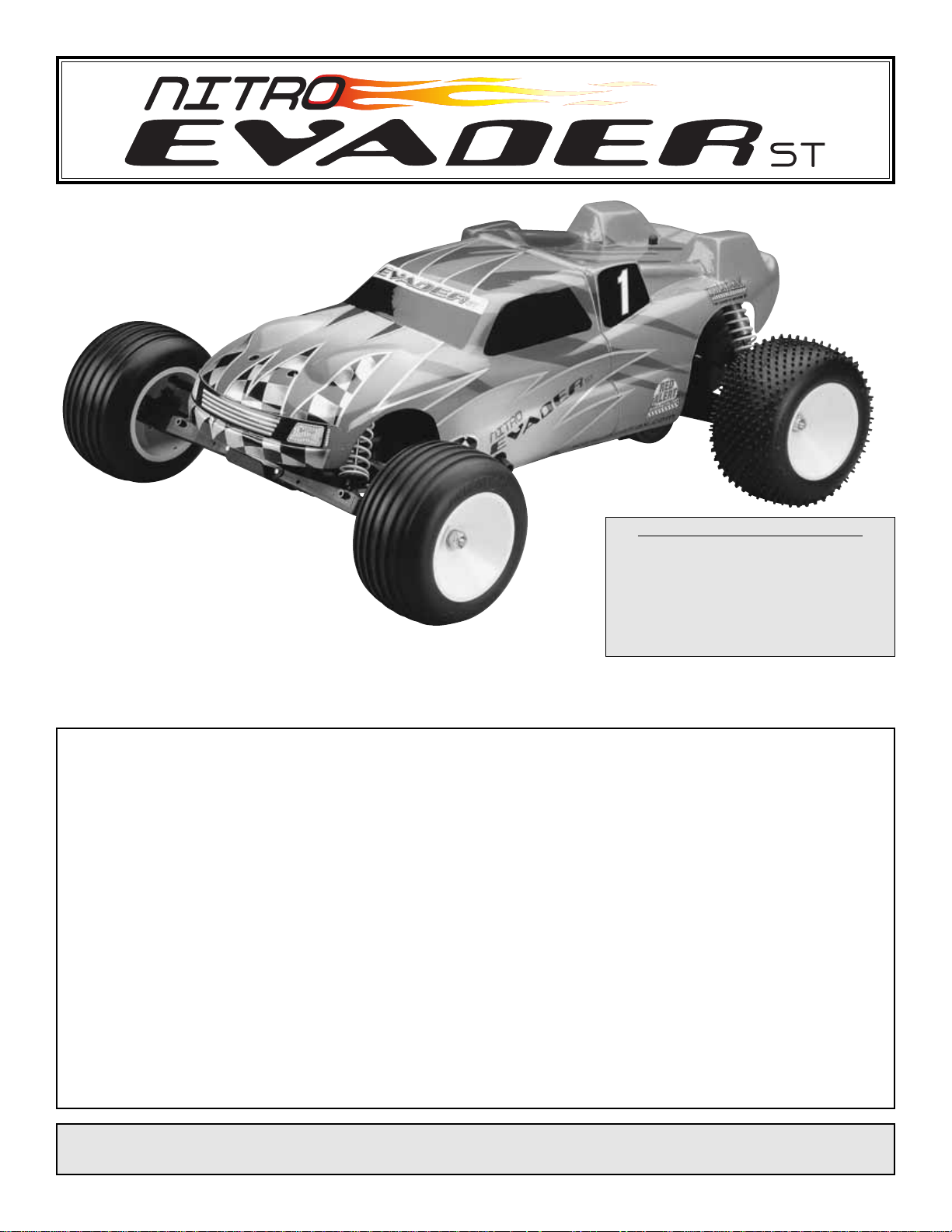
❏ 1. Install the transmitter antenna by screwing it into the hole on
the top of the transmitter.Give the antenna a mild tug to make sure
that it is properly secured in the transmitter.
❏ 2. Slide open the battery door on
the bottom of the transmitter. Install
eight (8) “AA” batteries
into the
transmitter in the configuration
molded into the plastic on the battery
holder. Reinstall the battery door.
Warning: Always extend the
transmitter antenna before operating
your vehicle.
❏ 3.T urn on the transmitter using the s witch on the side.The red light
on the side of the transmitter should light up. If there is no light on,
turn the transmitter off and check to ensure that the batteries are
making contact with the metal contacts in the battery holder. Make
sure the batteries are installed correctly.Turn the transmitter on and
check for the red light.If the red light appears, turn off the transmitter.
If the red light blinks, the batteries are low and should be replaced.
❏ 4. Remove the twist-tie from the receiver antenna wire. Locate
the antenna tube, and thread the receiver antenna through the
antenna tube. The antenna wire will be longer than the antenna
tube. DO NOT CUT OR COIL THE ANTENNA WIRE. Press fit the
antenna tube into the hole in the top of the receiver box.Tip: Run
the antenna wire through your fingers to straighten out the
kinks before
running through the antenna tube. Also, applying
a
small amount of soap and water to the antenna wire will help
lubricate the wire for threading into the antenna tube.
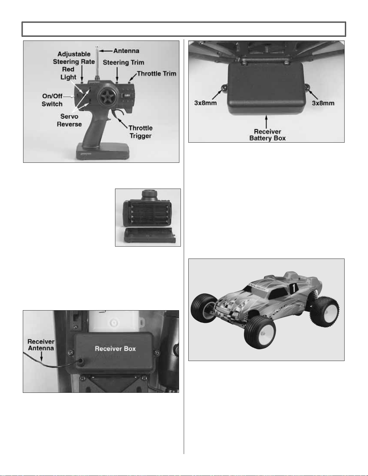
❏ 5. Remove the (2) 3x8mm pan head self tapping screws (L) from
the receiver battery box (65).Remove the receiver battery box lid
(66).
❏ 6. Remove the 4 cell receiver battery box from the radio box and
install (4) “AA” included batteries into the batter y holder. Follow the
configuration molded into the battery holder. Reinstall the receiver
battery holder back into the radio box. Plug the connector on the
receiver battery into the socket on the receiver switch wire. The
receiver battery connector can only be plugged in one way.Tuck the
wires into the groove in the radio bo x so that the y do not get crimped
under the radio box lid. Re-install the radio box lid and secure it in
place with the (2) 3x8 pan head self tapping screws.
❏ 7.Turn the transmitter and receiver on and chec k that the servos
are properly centered. Move the throttle and steering back and
forth to check that they are functioning properly.
❏ 8. Decal the body if desired.
❏ 9. Thoroughly soak the air filter element with the included air
filter oil. Work the air filter oil into the entire air filter element, then
using a clean, dry paper towel squeeze the excess air filter oil out
of the air filter element. Note: When the air filter element
becomes dirty, remove the air filter element from the Nitro
Evader and gently wash it out with warm water and dish soap.
After the air filter element is completely dry ,you can re-oil and
re-install it onto your Nitro Evader.
❏ 10. To continue, turn to page 9, “Carburetor Settings,” and
then “Breaking In the Engine.”
4
FINISHING THE NITRO EVADER ST RTR VERSION (DTXD62**)
Page 5
5
❏ 1. Install the “AA”batteries in the transmitter.
❏ 2. Install and extend the transmitter antenna.
❏ 3. Install (4) “AA”batteries into the receiver battery box (refer to
RTR section).
❏ 4. Connect the servos and receiver battery to the receiver.
❏ 5. Uncoil and extend the receiver antenna.
❏ 6. Adjust the servo trims of the transmitter to the neutral position.
❏ 7. Switch on the transmitter.
❏ 8. Switch on the receiver.
❏ 9. Operate the steering and throttle control. Make sure the
steering and throttle servo arms move in proportion to the
movement of the steering wheel and throttle trigger.
❏ 10.Switch off the receiver, then the transmitter.
❏ 1. Remove the Nitro Evader ST and the parts bag from the box.
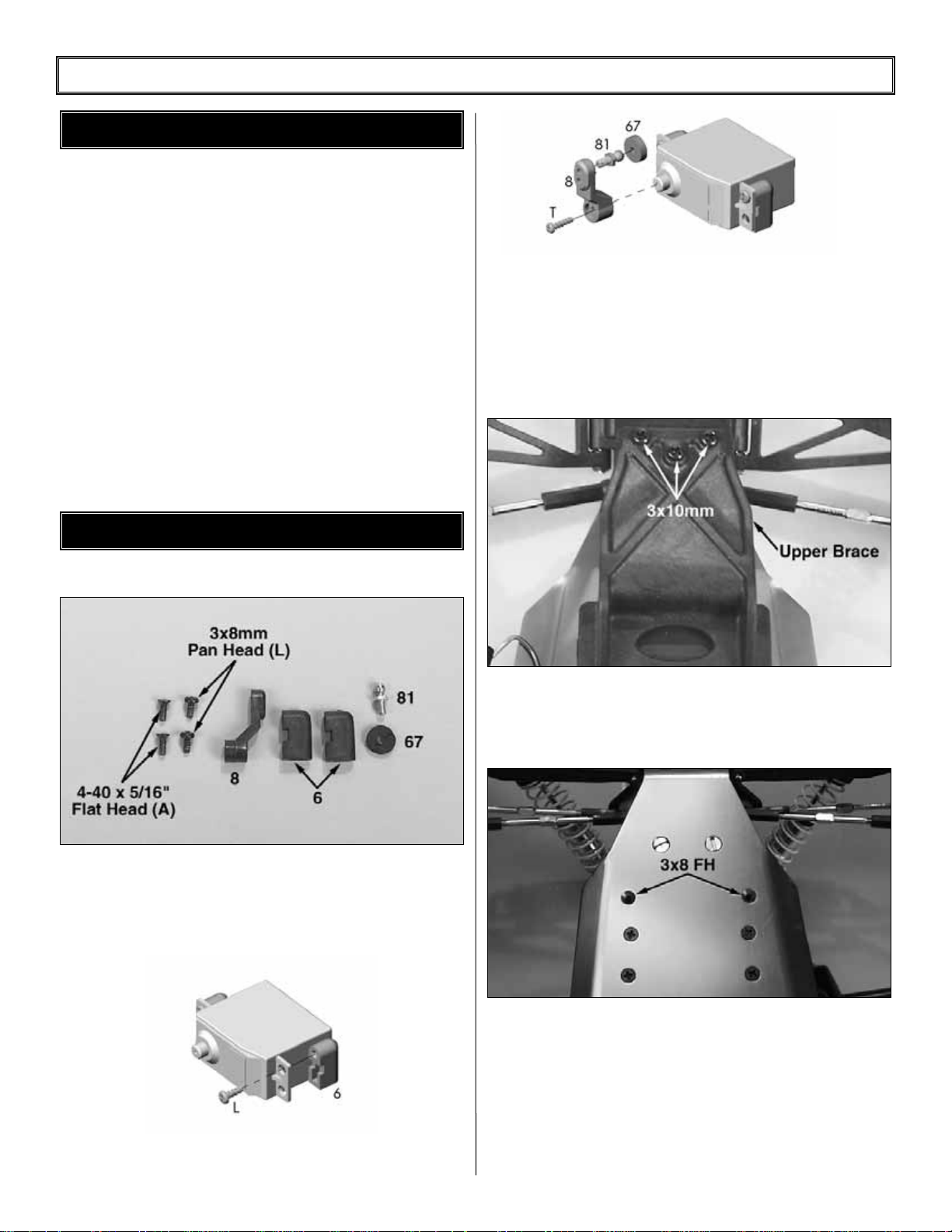
❏ 2. Locate and remove from the Parts Bag 2: steering servo
mounts (6), one servo arm (8) (determine which servo arm is
required for your radio system), one ball stud (81), one f oam washer
(67), two 3x8 pan head screws (L) and two 3x8 flat head machined
screws (A).
❏ 3. Attach the servo mounts (6) to the servo using the two (2)
3x8mm screws (L) as shown.
❏ 4. Install the ball stud (81) into the flat side of the steering servo
arm (8) in the upper hole. With the steering servo centered as
described in “Preparing the Radio System,” install the correct
steering servo arm onto the servo splines as sho wn abov e, making
sure that the servo arm is as close to vertical as possible. Note: If
the steering servo is not properly centered, the steering could be
off. Center the servo and then reinstall the servo horn screw,
securing the horn onto the servo.
❏ 5. Remove the (3) 3x10mm (I) and (2) 3x15mm screws (H) from
the top of the upper brace (52). Remove (2) 3x8mm flat head
machine screws (A) that hold the upper brace to the main chassis
(1). Remove the upper brace from the main chassis.
❏ 6. Install the steering ser vo into the mounting slot. Line up the
holes in the servo mounts with the two holes in the chassis. Note:
There are two different mounting holes in the servo mounts. Use
the appropriate holes for your servo. Install the two (2) 3x8 flat
head machined screws (A) through the bottom of the chassis into
the servo mounts.
❏ 7. Attach the steering link ball cup (5) onto the ball stud (81) on
the servo.Note: Do not reinstall the upper brace (52) back onto the
chassis (1) until later.
STEERING SERVO ASSEMBLY
PREPARING THE RADIO SYSTEM
FINISHING THE NITRO EVADER ST PRE-BUILT VERSION (DTXC0062)
Page 6
6
❏ 1.Remove the (2) 3x8mm pan head self-tapping scre ws (L) from
the receiver battery box (65). Remove the receiver batter box lid
(66). Note: (4) Four “AA”batteries should already be installed
from a previous step, but if not then install the batteries into
the receiver battery box. Install the receiver battery box into the
receiver battery holder.Tuck the wires into the groove in the radio
box so that they do not get crimped under the radio box lid.
Re-install the radio box lid and secure it in place with the (2)
3x8mm pan head self-tapping screws.
❏ 2. Route the receiver battery box wire through the shock tower
and across the top of the transmission. Tuck the receiver battery
box wire into the wire holder molded into the top of the
transmission case. Route the wire under the bottom of the engine
and along the side of the fuel tank. Note: Make sure the receiver
battery box wire is routed so that it cannot get caught in any
moving parts, like the engine’s flywheel. Secure the receiver
battery box wire to the fuel tank using a small tie-straps and the
molded tabs on the side of the fuel tank.
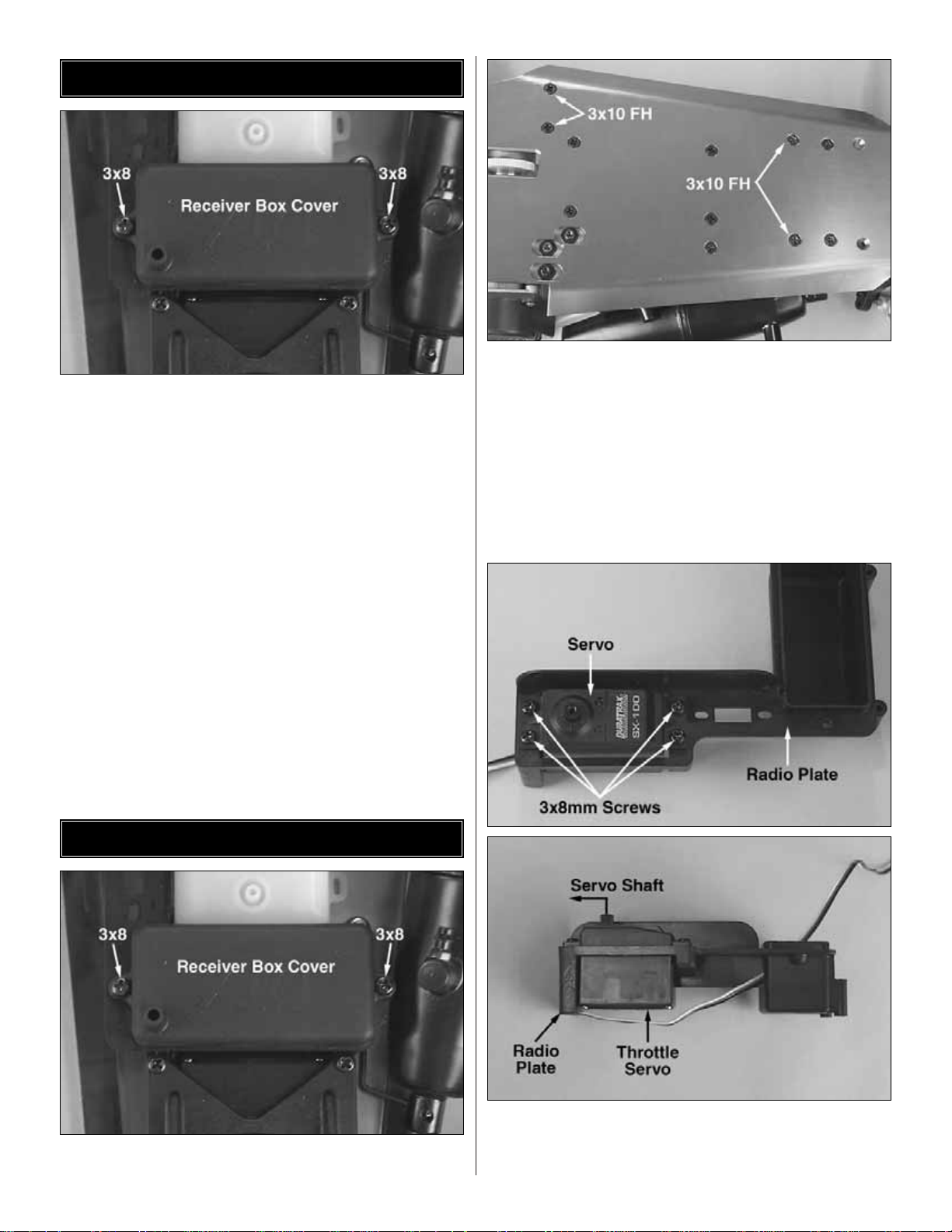
❏ 1. Remove the receiver box cover (69) from the radio plate (68)
by removing the (2) 3x8mm pan head self tapping screws (I).
❏ 2. Remove the radio plate/receiver box (68) from the chassis (1)
by removing (4) 3x10mm flat head machine screws (B) from the
bottom of the chassis.
❏ 3. Place the throttle servo into the radio plate as shown. Route
the servo wire through the hole in the receiver box. Note the
location of the servo output shaft. Secure the ser vo to the radio
plate using four 3x8mm screws (L).
RADIO PLATE INSTALLATION
RECEIVER BATTERY INSTALLATION
Page 7

7
❏ 4. Locate the switch that came with your radio system. Remove
the two screws from the face plate of the on/off switch and remove
the face plate.Note which position is “Off”before removing the face
plate. Insert the on/off switch through the bottom of the radio plate.
Then install the face plate over the top of the on/off s witch and place
the two screws back through the face plate into the on/off switch.
Note: Make sure the switch is situated so that when the switch
is pushed forward it is in the on position.This will prevent the
switch from shutting off in case of impact.
❏ 5. Run the end of the on/off switch that installs into receiver
through the same hole in the receiver box that you just ran the
throttle servo wire through. Connect the other end to the receiver
battery box.
❏ 6. Route the steering servo wire through the same hole
in the receiver box as the throttle servo and the on/off switch.
❏ 7. Reinstall the receiver box/radio plate onto the chassis using
the (4) 3x10mm flat head machine screws (B) on the bottom. Reinstall the upper brace (52) over the servo and reinstall the (3)
3x8mm pan head self tapping screws (I) and the (2) 3x15mm
socket head screws (H) in the top and (2) 3x10mm flat head self
tapping screws (B) in the bottom.
❏ 1. Insert the switch, throttle and steering ser vo plugs into the
receiver. Refer to the radio's instruction manual to determine
which slots to plug each of the servos into.
❏ 2.Install the receiver into the receiver box as shown.
❏ 3. Route the receiver antenna through the hole in the receiver box
lid (69) as shown in the drawing abov e.Locate the antenna tube, and
RECEIVER INSTALLATION
Page 8
8
thread the receiver antenna through the antenna tube.The antenna
will be longer than the antenna tube. DO NOT CUT OR COIL THE
ANTENNA WIRE. Press fit the antenna tube into the hole in the
chassis. Tip: Run the antenna wire through your fingers to
straighten out the kinks before running through the antenna
tube. Also, applying a small amount of soap and water to the
antenna wire will help lubricate the wire for threading into the
antenna tube. Re-install the receiver box cover back onto the
receiver box using (2) 3x10mm pan head self tapping screws (I).
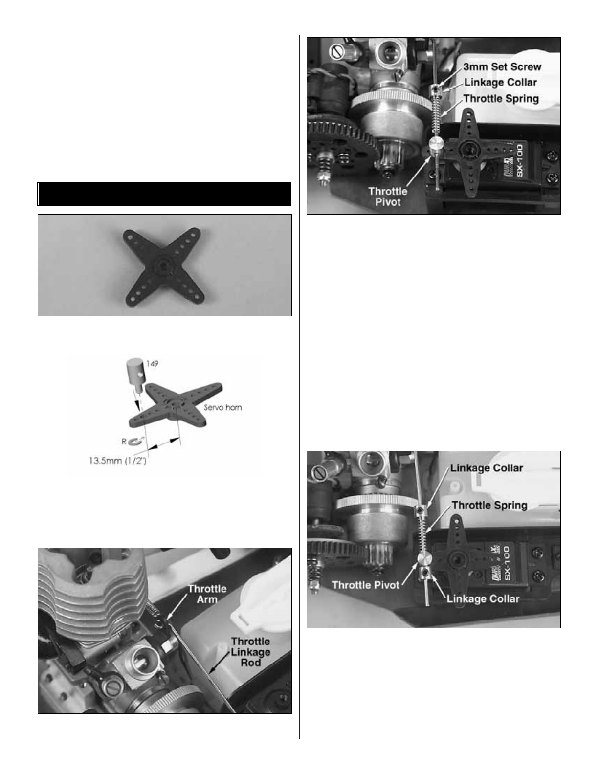
❏ 1.Locate an “X” shaped servo horn (like the one above) that
came with your radio system.
❏ 2.Install the throttle pivot (149) in the hole 13.5mm [1/2"] from the
center of the servo horn and secure it with the 2mm e-clip (R).
Note: Use a hobby knife to slightly enlarge the hole in the
servo horn for the throttle piv ot (149) to fit thr ough.The throttle
pivot must rotate freely.
❏ 3. Locate the short linkage rod (144) and install the “Z-bent” end
into the lower hole of the engine’s throttle arm as shown.
❏ 4. Install a 3mm set screw (K) into the linkage collar (146).Then,
slide the linkage collar onto the end of the throttle linkage (144)
and then the throttle linkage spring (148). Do not tighten the set
screw in the linkage collar yet.Install the straight end of the throttle
linkage through the hole in the throttle pivot (149). Install the
throttle servo horn onto the throttle servo. Do not install the servo
horn screw at this time. NOTE: Thread locking compound must
be applied in any step that requires a screw to be threaded into
another metal part. For example, when installing the set screws
into the linkage collars, apply a generous amount of thread
locking compound to the set screw before installing it into the
linkage collar.
❏ 5.Close the throttle to idle and make sure the servo horn is set as
shown in the above picture.Install a second 3mm set screw (K) into
another linkage collar (146) and then slide the linkage collar (146)
onto the throttle linkage (144). Slide the linkage collar (146) against
the throttle pivot (149) and tighten the 3mm set screw .Then slide the
previously installed linkage collar and spring against the other side
of the throttle pivot and apply a slight amount of tension against the
spring. Now tighten the set screw in the linkage collar. Note:This is
a good starting point for the linkage. Slight adjustments may
need to be made to obtain optimal performance.
THROTTLE LINKAGE
Page 9

❏ 1. Install the Z-bent end of the brake linkage rod (145) into a hole
16.5mm (5/8") away from the center of the servo horn.
❏ 2. Slide the straight end of the brake linkage wire (145) through
the brake arm (128).
❏ 3. Install the brake linkage tube (147) onto the end of the brake
linkage wire. Install a 3mm set screw (K) into the linkage collar
(146) and then slide the linkage collar onto the end of the brake
linkage wire.
❏ 4. With the throttle at idle, slide the linkage collar (146) and tube
(147) against the brake actuator rod (128) so that a slight amount
of brake is applied.Tighten the 3mm set screw in the linkage collar.
You can check to see if the brakes are applied by gently rolling the
vehicle on a flat surface. If the brakes are applied there will be a
slight amount of resistance.
❏ 5. Remove the throttle servo horn from the throttle ser vo.Turn
the transmitter on and then the receiver. Allow the throttle servo to
center.Then, reinstall the throttle servo horn back onto the throttle
servo as shown.
❏ 1. Thoroughly soak the air filter element with the included air
filter oil. Work the air filter oil into the entire air filter element, then
using a clean, dry paper towel squeeze the excess air filter oil out
of the air filter element.
Note: When the air filter element becomes dirty, remove the
air filter element from the Nitro Evader and gently wash it
out with warm water and dish soap. After the air filter element
is completely dry, you can re-oil and re-install it onto your
Nitro Evader.
The High-Speed Needle
The “high-speed” needle is sticking up from the side of the carb.It is
located in the brass housing, just above the fuel inlet. It controls the
fuel to air mixture of the carb.The needle setting for break-in is 2 turns
out from fully closed. Once the engine is broken-in, the high-speed
needle would typically run from 1-1/4 to 1-3/8 turns out from closed,
depending on the temperature, humidity and altitude above sea le v el.
To richen the mixture turn the needle counterclockwise, to lean it turn
the needle clockwise.
CARBURETOR SETTINGS
INSTALL & OIL AIR FILTER
BRAKE LINKAGE
9
Page 10
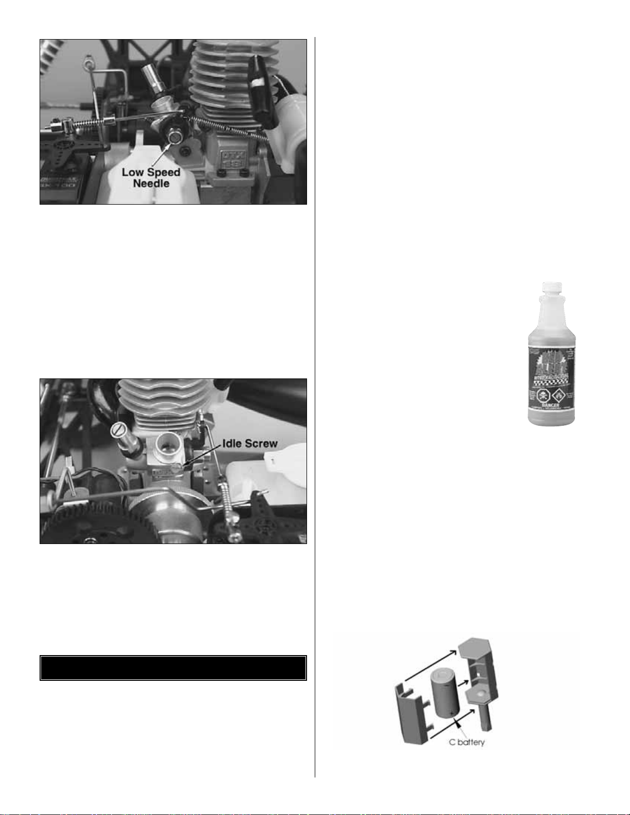
The Low-Speed Needle
The “low-speed” needle located on the side of the carburetor. It
controls the fuel to air mixture at low throttle settings. There is a
simple way of adjusting the low-speed needle correctly called the
“pinch test.”With the engine at idle, pinch the fuel line and listen to
how the engine speeds up or slows down. If the engine increases
its speed for about 3 or 4 seconds and then loses speed, the
needle is set correctly.If the engine loses RPM quickly, it is set too
lean and the low-speed needle needs to be opened
(counterclockwise) to richen the mixture. Pinch again to check the
mixture. If the engine takes longer than 5 seconds to slow down,
lean (clockwise) the low-speed needle and then pinch again to
check the mixture.Note: Make sure the high speed needle is set
properly before the low speed needle is adjusted.
The Idle Stop Screw
On the front of the carburetor, there is a black screw. This is called
the idle stop screw. This increases or decreases the idle RPM
without changing the fuel to air mixture. The barrel should be
approximately 1.5mm (between 1/32" and 1/16") from fully closed.
Note:This engine was designed to racing tolerances and may
take longer than 5 tanks to fully break-in.
To insure long life and good performance from your DuraTrax .18
engine, you MUST break-in the engine. The break-in period is
critical for long life of the internal parts of the engine.This should be
done over the first 5 tanks of fuel.
Some Things To Remember During Break-In
❏ 1. Run with the body off.This will keep the engine
cooler.
❏ 2. Keep the air cleaner on at ALL times
❏ 3. Run on a smooth, hard surface. An empty parking lot
is perfect.
❏ 4. Use the same fuel that you will use for normal running.
❏ 5. Resist the urge to accelerate and decelerate the
truck quickly.
❏ 6. Break-in puts stress on the glow plug and you can burn it
out during break-in. Make sure you have an extra plug or
two on hand.
❏ 7. Do NOT overheat the engine. You can check the head
temperature by using one of the temperature gauges that
are available or by putting a drop of water on the top of the
cylinder head. If the water boils away immediately, shut off
the engine and allow it to cool. If it takes more than 4
seconds to boil away, the engine is at proper running
temperature for break-in.
Before running the engine, read the manual and watch the
engine video that came with this kit.
Fuels
Use fuels that are specially formulated for car
and truck engines and have a nitro content
between 10-20%. DuraTrax Red Alert
(DTXP0520) fuel is specially formulated for
R/C car engines like the DTX .18.
There are several simple steps to starting the engine:
❏ 1. Install a glow plug.This threads into the top of the cylinder
head.
❏ 2. Fueling - Fill the tank almost to the top. Leave a little air at the
top of the tank.
❏ 3.Prime the Engine (when cold) - Wrap you finger with a shop
towel and place it over the tuned pipe's exhaust exit.Pull the recoil
gently until you can see fuel reach the carburetor (looking through
the fuel tubing).Note:The engine should not require priming when
hot unless you ran out of fuel).
❏ 4. Open the high speed needle valve exactly 2 turns out
(counterclockwise) from fully closed. The high-speed needle is
sticking up from the carburetor inside the brass housing.All of the
carburetor settings are adjusted with a flat bladed screwdriver.
❏ 5. RTR Version ONLY: Install the included "C" size batter y into
the included glow starter as shown.
BREAKING-IN THE ENGINE
10
Page 11

❏ 6. Install the glow starter onto the glow plug and gently press the
top of the glow starter down and turn in a clockwise direction.This
will lock the glow starter onto the glow plug. To remove the glow
starter, gently press down on the top of the glow starter and turn
counter clockwise.
❏ 7. Star t the engine by pulling the recoil - Use short, quick pulls.
DO NOT pull the recoil starter's string to the end.You only need 10
to 12 inches of pull to start the engine.
❏ 8. Your truck is equipped with a throttle return spring. It is
installed between the throttle servo horn and the recoil starter.This
will return the throttle to idle if there is a loss in power for the onboard radio equipment.
Many times it is helpful to start the engine at around half throttle.
Have a friend pull back on the throttle some while you start the
engine. This may be an indicator that the low speed needle setting
needs to be adjusted. When the engine star ts, immediately return
the throttle to idle. If this is not done the engine can over-rev and
cause engine damage. If the engine is difficult to turn over with the
recoil starter, especially if it is brand new , loosen the glo w plug a half
turn before starting the engine. This allows some compression to
escape, but the engine will still start.Make sure you tighten the glow
plug after the engine starts. If the recoil starter is still difficult to pull,
the engine is flooded - there is too much fuel inside the engine.
Remove the glow plug, and then turn the engine upside down and
pull the recoil 5 or 6 times.This will clear the engine of fuel, and you
will notice the recoil pulls easier. Replace the glow plug and repeat
the starting procedure.
Tanks 1-2
Your first two tanks of fuel should be running the truck at a very rich
high-speed needle valve setting. This allows the fuel to carry as
much oil as possible into the engine to lubricate the internal parts
during the break-in.
❏ 1. After a minute or two of running back and forth at medium
speeds, slowly accelerating and decelerating the truck, make sure
the engine is not overheating by putting a drop of water on the
cylinder head.If it boils away within 4 seconds, stop the engine and
allow it to cool. Open the high-speed needle around a 1/4 turn
before starting again.This is a good habit to get into every time you
run to ensure that the engine does not overheat during any run.
Looking at the smoke that comes out the exhaust is also an
indicator of how rich or lean the engine is running.If there is a good
amount of smoke coming out of the exhaust, then chances are
good that you are running rich.
❏ 2. Run the truck back and forth at a medium speed until the tank
is almost out of fuel. Do not allow the tank to run out of fuel. This
leans out the engine and can cause overheating.
❏ 3. Stop the engine and allow the engine to cool before the
second tank.This normally takes around 10 minutes.
How To Stop Your Engine
You may have been wondering how to stop the engine. All you
have to do is pinch the fuel line that runs to the carburetor and from
the bottom of the fuel tank. Pinching this line will restrict the fuel
flow and the engine will quit within a few seconds.
Tanks 3-5
Turn in the needle valve (clockwise) around 1/8 turn from the
previous setting for each additional tank. Run the truck back and
forth.You should notice that the truck will perform better during each
run. Stop the tr uck periodically to check for overheating. If it is too
hot, stop the engine.Wait for it to cool, and then turn the high speed
needle valve counterclockwise 1/8 turn, and restart. After the 5th
tank, you should be near to the peak performance of the engine.
10 Ways To Ensure A Long Life From Your Engine:
❏ 1. Keep your engine clean. Dirt will act as insulation on an
engine. It will not be able to shed heat as easily. Use a good air
filter to keep dirt out of your engine and clean it often.
❏ 2. Do not over-lean your engine.
❏ 3. Do not run your engine with little or no load. Don't throttle up
the engine to full throttle when the wheels are not in contact with
the ground.
❏ 4. Do not overheat the engine. This goes along with keeping it
clean and not over-leaning the engine.
❏ 5. Do not use a fuel with a low oil content. Make sure you use a
fuel from a reputable manufacturer, such as DuraTrax Red Alert.
❏ 6. Avoid using old fuels in the engine. Always run all of the fuel
out of the engine.After running for the da y, use an after-run oil and
work it into the engine by turning the flywheel or pulling the engine
recoil slowly.
❏ 7. Do not use a fuel with a nitromethane (often called nitro)
content over 20%.
❏ 8. Do not scratch the piston or cylinder sleeve. Avoid jamming
something into the exhaust port when removing or reinstalling the
clutch or flywheel. Use a special tool called a crankshaft-locking tool,
which is installed in the glow plug hole.
❏ 9. Do not use silicone sealer on the engine joints.Silicone sealer
contains acetic acid, which is corrosive if it gets inside your engine.
❏ 10. Do not allow any water to get inside the engine.This sounds
easy, but temperature changes can cause condensation inside the
ENGINE MAINTENANCE
11
Page 12

engine. This is a good reason to use an after-r un oil. Store your
engine inside the house, not in a garage or shed where there will
be temperature extremes.
Glow Plug
The glow plug is an item that will wear out and need replacement
from time to time. It is a good idea to remove the glow plug before
your first run, connect the plug to the glow starter and see how well
it glows.You should see a bright orange glow from the filament. If
a coil or two will not glow or the plug will not glow at all, replace the
plug.If the engine quits when you remo ve the glo w starter, the plug
might need to be changed, although this may be because you are
running too rich and need to screw in your high-speed needle
some. Look at the glow plug when you are running the engine. If
you see some bubbles coming from around the plug, replace the
glow plug (copper) gasket, or both the plug and gasket.The only
real way to test a glow plug is to replace it.Make sure you have a
spare plug (Siver Sport Glow Plug-DTXG3001) or two on hand
every time that you run the Nitro Evader ST.
Fuel
Fuel can go bad. The main ingredient in model fuel is methanol,
which is basically alcohol. Alcohol will absorb water out of the air,
so keep your fuel jug capped at all times.Store your fuel out of the
sunlight and in a cool place. Bad fuel is one of the most difficult
problems to diagnose in engines. If you have tried everything you
can think of to remedy an engine that is not running correctly, try
using some fresh fuel.
Maintenance
The fuel line is susceptible to pinhole leaks. You cannot see the
hole in the fuel line, but if you see air bubbles in the line going to
the carburetor, replace the fuel line. Another symptom of a leak in
the fuel line is a surging engine.A properly tuned engine will surge
when the air bubbles hit the carb. It is basically leaning out the
mixture.
To keep dirt out of the engine, we recommend that you use an
inline fuel filter (Clean Flow Fuel Filter-DTXC2551) on the fuel line
running from the fuel tank to the carburetor.Dirt can get caught in
the needle seat and cause an inconsistent running engine. If you
suspect that some dirt has lodged itself in the carb, remove the
needles and clean the carb with denatured alcohol or fuel. It can
help to use compressed air to blow out the fuel passages as well.
Dirt can get into your carburetor and engine through the air filter.
Ensure that your air cleaner has a good seal to the top of the carb.
Periodically wash the air cleaner foam element and re-oil the filter.
Any air cleaner that has a torn element or a bad seal should be
replaced immediately.
Overheating
One of the worst things you can do to your engine is overheat it.
The oils that lubricate the engine are carried in the fuel. If your
engine is set too lean, there will not be enough oil in the engine to
lubricate the internal par ts. This will cause premature wear in the
engine and cause damage. We have talked about overheating in
other parts of this manual, but we want to stress the proper
techniques to check for overheating. The easiest way of checking
the temperature of the cylinder head is using one of the available
temperature gauges. This will give you a direct reading of the
cylinder head temperature. Do not let the head temperature
exceed 250° Fahrenheit (121° Celsius). Another way of checking
the head temperature is to put a drop of water on the cylinder
head. If it boils away immediately, the high-speed needle is set too
lean. If the water boils away in 3-5 seconds, the engine is within
proper operating temperatures.If the water boils away longer than
5 seconds, the mixture is set rich which is preferable when
breaking in the engine. Otherwise lean the mixture some and
retest after a minute of running.
The ball differential has been adjusted at the factory for proper “breakin”. Do not tighten the differential before the truck has been properly
broken-in or you can damage the differential.
After running the truck for 2 or 3 tanks of fuel, the ball differential
will require readjustment. This is the “normal” break-in period for
the ball differential. You will hear a “squealing” sound when
accelerating from a stop and the truck will accelerate slower.This
indicates that the differential is properly broken-in and now
requires adjustment.Do not run the truck again until the differential
is properly readjusted as follows.
Adjusting the differential is quick and easy. Access the adjusting
screw by disconnecting the rear camber link (using pliers) at the
right rear wheel. Rotate the wheel and CV shaft out of the way.
While holding the left rear tire, tighten the adjusting screw by
inserting the included 3/32" L-wrench into the cap screw on the
right side of the ball differential. The screw should be tightened
until it is “just snug.” Caution: Do not over tighten the adjusting
screw or you will damage the differential. Next, loosen the screw
1/8 of a turn.
Reinstall the CV shaft back into the differential and reattach the
camber link. The ball differential may need occasional adjustment
to maintain performance.
BALL DIFFERENTIAL BREAK-IN
12
Page 13

13
The following information has been provided to help maintain and tune the Nitro Evader ST.
ASSEMBLY GUIDE
1. Attach the front bulkhead (51) to the chassis by
installing (2) 3x10 flat head self tapping screws (A) into
the (2) rear holes.
2. Secure the bumper (2) and bulkhead (51) onto the
chassis (1) using (2) 3x8mm flat head self tapping
screws (B).
3. Install the front hinge pin brace (50) against the front
of the front bulkhead (51). Then attach and secure the
front suspension arms (38 & 39) to the front bulkhead
(51) using the inner front inner hinge pins (104).
4. Secure the rear of the front inner hinge pin (104) with
a 2.5mm e-clip (S).
5. Secure the front bulkhead brace using 2.5mm e-clips
(S).
6. Attach the front shock tower (49) to the front bulkhead
(51) using (4) 4-40x3/8" socket head screws (C).
7. Secure the front body mount (57) to the front shock
tower (49) using (2) 4-40x3/8" socket head screws (C).
8. Attach the top of the front bulkhead (51) to the upper
plate (52) with (3) 3x10 pan head screws (I).
Bulkhead, Bulkhead Brace, Front Suspension Arm
Front Shock Tower, Front Bumper
1. Attach the front hub carriers (28) to the front suspension ar ms (38 & 39)
using the outer front hinge pins (95).
2. Install the front axles (91) into the knuckle arms (24 & 25).
3. Install two kingpin spacers (Y) onto each kingpin (94).
4. Insert the knuckle arms (24 & 25) into the front hub carriers (28) and then
secure them in place with the kingpins (94).Note:The king pin spacers go
on the top of the hub carriers.
5. Secure the kingpins (94) in place using 2mm e-clips (R).
6. Install a 3mm set screw (K) into the axle (91) to secure the kingpins (94)
in the axle.
Front Knuckle Arm, Hub Carrier, Axle
Page 14
14
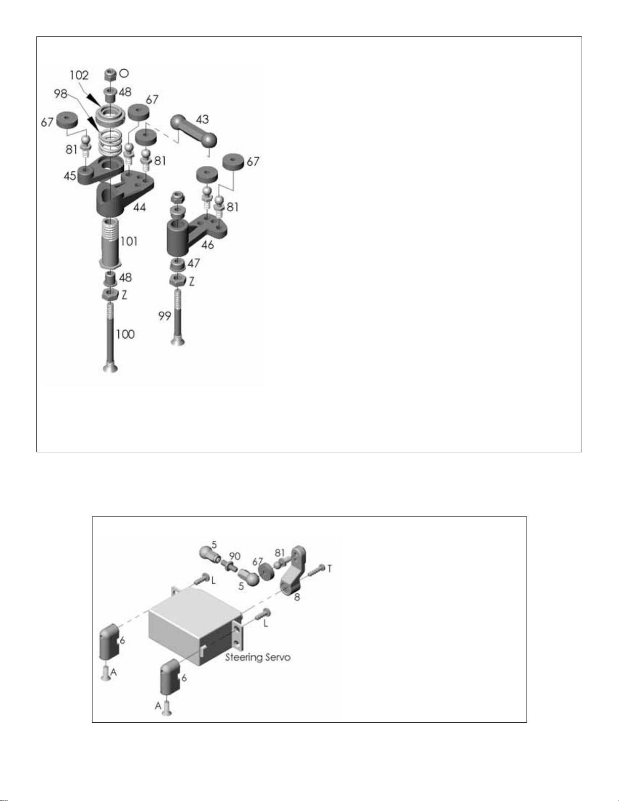
1. Insert the two bellcrank screw posts (99 & 100) into the bottom of
the chassis (1). The long screw post (100) should be installed on the
left side of the Nitro Evader chassis when viewed from the rear. Secure
the bellcrank screw posts (99 & 100) to the chassis (1) with the 4mm
hex nuts (Z).
2. Install ball studs (81) into the right bellcrank (46) in the holes shown.
3. Insert a plastic bushing (48) into each end of the right steering
bellcrank (46). Make sure the bushings are fully seated.
4. Slide the assembled right bellcrank onto the short aluminum
bellcrank screw post (99).
5. Install ball studs (81) into the lower left bellcrank (44) in the holes shown.
6. Insert the threaded aluminum servo saver hub (101) into the bottom
of the lower left steering bellcrank (44). Note: The aluminum servo
saver hub is designed to key into the bottom of the lower left
steering bellcrank. Make sure that the hex in the hub fully seats
in the bellcrank.
7. Install a ball stud (81) into the upper left steering bellcrank (45).
8. Insert a plastic bushing (48) into each end of the threaded post
guide (101). Again, make sure the bushings are fully seated.
9. Slide the servo saver hub (101) and lower left bellcrank assembly
onto the long servo saver shaft (100). Then install the upper left
steering bellcrank (45) onto the lower left steering bellcrank (44).
Note: The upper and lower left steering bellcranks are designed
to key together.
10. Place the servo saver spring (98) on top of the upper left steering
bellcrank (45).
11. Secure the left bellcrank assembly together with the aluminum
servo saver spring adjuster (102).Note:The servo saver spring adjuster is mac hined on one side for the serv o sa ver
spring to fit into. Make sure this side goes down against the servo saver spring.The servo saver spring will need
to be properly adjusted once the entire steering bellcrank assembly has been installed on to the Nitro Evader.
12. Slide the assembled left bellcrank assembly onto the screw post (100).Attach the left and right bellcranks with the one
piece molded link (43).
Steering Bellcrank Assembly
1. Attach the servo mounting lugs (6) to
the rear of the servo mounts on the servo
using (2) 3x8 self tapping screws (L).
2. Install a ball stud (81) into the steering
servo horn (8).Insert the ball stud into the
hole furthest from the center.
3. Install the steering servo horn onto the
servo.Note: Make sure the transmitter,
steering servo and servo horn are
properly centered before securing the
servo horn to the servo.
4. Secure the servo to the chassis with
(2) 3x8mm flat head screws (A).
Servo
Page 15

15
1. Attach the rear suspension plate (41) to the chassis (1) using (4) 3x8mm flat head screws (A).
2. Attach the rear suspension arms (36 & 37) to the rear suspension plate (41) using the inner rear hinge pins (97 & 104).
3. Secure the inner rear hinge pins (97 & 104) in place using (2) 2.5mm e-clips (S).
4. Install (2) ball studs (81) into the appropriate holes in the transmission brace (42).Note:The stock setting is the lower
inner holes. Make sure that the ball studs are in the same hole location on both sides.
5. Install the transmission brace (42) onto the gearbox using (2) 4-40x3/8" socket head screws (C). Note: Do not install
the two screws through the chassis into the rear bulkhead.You must install the receiver battery box bottom first.
6. Attach the top of the rear shock tower (40) to the transmission brace (42) using (2) 4-40x3/8" socket head screws (C).
Note: Make sure the screws pass through the shock tower, chassis and into the rear bulkhead.
7. Attach the receiver battery box bottom (65) to the chassis (1) with (2) 3x10 flat head self tapping screws (B). Also, use
(2) 4-40x3/4" socket head screws (E) to secure the receiver battery box bottom (65) to the rear shock tower (40).
8. Secure the receiver battery cover (66) to the receiver battery bottom (65) using (2) 3x5 pan head screws (L).
Rear Shock Tower, Rear Bulkhead, Rear Transmission Plate,
Rear Suspension Arm, Receiver Battery Box
1. Install axle spacer (88) in the center of each rear hub.
2. Install (2) 5x10mm bearing (108) in both of the rear hubs (26 & 27).
3.Install a ball stud (81) into the center hole of the rear hubs (26 & 27).
4. Place a 3mm plastic spacer (58) on each side of the rear hubs (26
& 27). Secure the rear hubs (26 & 27) to the rear suspension ar ms
(36 & 37) with the 3mm outer rear hinge pins (107).
5. Secure the outer rear hinge pins (107) with 2.5mm E-clips (S).
6. Install the rear axles (79) through the bear ings in the hubs.
7.Slide a rear axle washer (82) onto the axle then install a
2.5x12mm spring pin (117) into the rear axle.
Rear Hub, Rear Axles
Page 16

16
1. Place one of the differential thrust washers (121) onto the 3x25mm cap screw (G).
2. Lubricate the differential thrust washer (121) and then install the plastic thrust ball holder (19) and 1/16" thrust balls
(113) using silicone grease.
3. Lubr icate the other differential thrush washer (121) and install it on top of the 1/16" thrust balls (113) and holder (9).
4. Insert the screw and thrust ball assembly into the left outdrive (92).
5. Apply a small amount of grease to one of the differential rings (120) and place it onto the left outdrive (92).The grease
should hold the differential ring (120) in place.
6. Install a 5x9mm bear ing (109) onto the left outdrive (92).
7. Install the 3/32" differential balls (112) into the differential gear (18).
8. Install a 5x9mm bearing (109) into the center of the differential gear (18) and install the gear onto the left outdrive (92).
9. Install the other differential ring (120) onto the right differential outdrive (93).
10. Insert the differential spring (123), lock nut holder (22) and the 3mm lock nut (O) into the end of the right differential
outdrive (93).
11. Join the left and right differential outdrives (92&93) together and tighten the 3x25mm cap screw (G) until the diff erential
gear cannot be turned while both differential outdrives are being held.Note: Be careful not to over tighten the differential.
The differential will require fine tuning once it has been installed into the truck. (The diff can be properly adjusted by
tightening the diff bolt (G) until snug and then back off 1/8 turn.)
Ball Differential
Note: When installing the bearings make sure they are
fully seated. If the bearings are not fully seated the
gearbox halves may not properly fit together or may
cause binding.
1.Install a 5mm washer (X) onto each end of the top shaft (83).
2. Install a 5x10mm bearing (108) into the upper hole of the
right gearbox half (20).
3. Install the top shaft (83) into the 5x10mm bear ing (108)
that was just installed into the right gearbox half (20).
4. Install the 2x10mm spring pin (116) into the top shaft (83)
5. Install a 5x10mm bearing (108) into each side of the idler
gear (17).
6. Install the idler gear shaft (89) into the idler gear bearings.
7. Install the idler gear into the r ight gearbox half (20).
8. Install a 12x18mm bearing (110) into the lower hole in the
right gear box half (20).
9. Install the ball differential into the 12x18mm bearing (110)
that was just installed into the right gear box half (20).
10. Insert a 12x18mm bearing (110) and 5x10mm bearing (108) into the left gearbox half (21).
11. Install the two gearbox halves (20&21) together.Make sure the two gearbox halves properly fit together.
12. Secure the two halves together with the 4-40x3/8" socket head screw (C).
Gearbox
Page 17

17
1. Install the brake arm (128) into the outer brake plate (153) and secure the brake arm into place using the push nut (CC).
2. Insert the two 4-40x1/2" socket head screws (D) into the outer brake plate (153).Then install the brake spacer (127)
and the inner brake plate (23) onto the 4-40x1/2"socket head screws (D).
3. Install the brake nut (7) onto the top shaft (83) of the transmission.
4. Insert the brake disk (96) between the two brake plates (23 & 153) and then install the brake mechanism onto the side
of the gearbox. Notice that the brake disk (96) keys onto the brake nut (7).
5. Install the inner slipper plate (84) onto the top shaft (83). Make sure the notch in the inner slipper plate (84) keys onto
the 2x14 spring pin (116) in the top shaft (83).
6. Place the slipper pad (64) and outer slipper plate (85) onto the top shaft (83).Make sure the slipper pad (64) is properly
centered between the two plates (84 & 85).
7. Install a slipper bushing (86) into the spur gear (16).
8. Slide the spur gear (16) onto the top shaft (83) and secure it to the outer slipper plate (85) using (2) 3x6mm screws
(BB) and (2) 3mm lock washers (P).
9. Slide a 3mm flat washer (121) 3mm brass washer (W) and then another 3mm washer (121) onto the top shaft (83).
10.Install the slipper spring (87), 3mm washer (121), and then the 3mm lock nut (O).Refer to page 19 for adjusting the slipper .
Brake, Slipper Clutch
Shocks
10.Thread the preload adjuster (122) onto the shock body.
11. Install the shock spring (70 & 71) onto the shock body
(75 & 76).
12. Secure the shock spring in place with the shock
retainer (32).
1. Install a 2.5mm e-clip (S) onto the shock shaft (77 & 78). Install the e-clip into the
groove closest to the center of the shaft.
2. Place the shock piston (4) on top of the 2.5mm e-clip (S).
3. Secure the shock piston (4) in place with a 2.5mm e-clip (S) in the groove towards the
end of the shaft.
4. Install a shock o-ring (114), then the plastic spacer (35), and then another
shock O-ring (114) into the shock seal holder (33). Secure all of the par ts
in the shock seal holder (33) using the shock seal cap (34).
5. Install the shock shaft assembly into the shock seal assembly.
6. Fill the shock with fluid. Then install the shock seal
assembly into the shock body (75 & 76).
7. While tightening the shock seal assembly down,
work the shock shaft and piston up and down
to help remove any air and excess oil
that may be trapped in the shock.
8. Thread the shock shaft end (31) onto
the end of the shock shaft (77 & 78).
9. Install the shock ball (106) in the
shock end (31).
Page 18

18
1. Secure the radio plate (68) to the chassis (1) using (4)
3x8mm flat head screws (A).
2. Secure the radio box cover (69) to the radio plate (68)
using (2) 3x10mm self tapping screws (L).
3. Attach the fuel tank (56) to the chassis (1) using (4)
3x8mm flat head screws (A).
Fuel T ank, Radio Plate
1. Place the air filter element (135) onto the air filter base (136).
2. Secure the air filter element (135) onto the base (136) by installing the air filter top
(134) and securing it all together with the 3x8mm flat head self tapping screw (A).
3. Install the air filter neck (137) onto the bottom of the air filter base (136). Secure
the air filter neck (137) to the base using a tie-strap (151).
4. Secure the other end of the air filter neck (137) to the engine using another tiestrap (151).
Air Filter
1. Secure the engine onto the engine mount (3) using (4) 4-40x3/8" socket head screws
(C) and (4) 3mm lock washers (P). NOTE: Make sure a generous amount of thread
locking compound is applied to the screws before installing them.
2. Secure the engine mount (3) to the chassis (1) using (6) 3x8mm socket head screws (A).
Engine Mount, Clutch
1. Install the flywheel collet (129) onto the engine’s crankshaft.
2. Install the flywheel (130) onto the engine’s crankshaft, making sure the
collet (129) fits properly into the flywheel (130).
3. Install a crankshaft locking tool (not included) into the engine and install
the pilot shaft (133). Note: Make sure you thoroughly tighten the pilot
shaft onto the engine’s crankshaft.
4. Install the two clutch shoes (131) onto the flywheel pins. Note the
direction of the clutch shoes in the drawing.The clutch shoes should
be installed in this direction for optimal performance.
5. Install the clutch spring (132) into the groove of the clutch shoes (131).
6. Install a 5x8 flanged bear ing (103) onto the pilot shaft (133).
7. Install the clutch bell (80) onto the pilot shaft (133)making
sure the bearing fully seats into the clutch bell (80).
8. Install the second 5x8mm flanged bearing (103) into
the end of the clutch bell (80).Again, make sure the
bearing is fully seated into the clutch bell (80).
9. Install a 5mm washer (X) onto the end of the
pilot shaft (133). Secure the clutch assembly
with a 4mm e-clip (DD).
Page 19

19
BEFORE EACH RUN
❏ 1. Check to make sure that all screws are tight and there
are not any screws missing.
❏ 2. Before running always check the condition of y our radio
system batteries and replace/recharge if necessary.
❏ 3. Check to make sure that all of the moving parts of the
Nitro Evader move freely and do not bind.
❏ 4. Check the fuel tank and fuel lines for leaks.
❏ 5. Before star ting the engine, turn on the radio and make
sure the servos move easily and in the proper direction.
❏6.Inspect the air cleaner for a torn or damaged element.Also
look for dirt in the air cleaner element and wash it if necessary .
❏ 7. Check for broken or damaged parts. Replace any
broken or damaged parts before running the Nitro Evader.
Running of the Nitro Evader with broken or damaged parts
could result in damage to other parts.
❏8.Check to make sure that all wires are properly connected.
AFTER EACH RUN
❏ 1. Clean any large globs of dirt or debris from the chassis
and moving parts.
❏ 2. Drain the fuel tank of any leftover fuel.DO NOT return
the fuel to your fuel jug.
❏ 3. Check for any broken or damaged parts.This way parts
may be replaced before the next run.
❏ 4. Put some after-run oil in the carburetor and turn the
flywheel several times to work the oil into the engine. This
will protect the engine from rusting, especially when stored
for a long period of time.
AFTER EVERY 10 RUNS
❏ 1. Check to make sure that the bearings are free of dirt
and debris, and roll smoothly.
❏ 2. Check the shocks for oil leakage. If the shocks have
leaked any shock fluid out, you should properly refill the
shocks for best performance.
❏ 3. Make sure the servo saver moves freely and does
not bind. This will help prevent stripping of the servo
during running.
❏ 4. Check for proper gear mesh between the spur and
clutch bell.
When tuning the Nitro Evader make sure that you have
equal lengths from one side to the other on the shocks,
camber rods and steering rods. Also, make sure to have the
shock pre-load adjusters at the same setting from left to
right.They do not have to be the same front to rear.
CASTER
Caster refers to the angle at which the kingpin is at in
relation to the surface when viewed from the side .0 degrees
of caster means that the kingpin is straight up and down.
The Nitro Evader comes stock with 30 degrees of caster.
CAMBER
Camber refers to the angle at which the tire and wheel ride
in relation to the ground when viewed from the front or rear.
Negative camber is when the tire and wheel lean inward and
positive camber is when the tire and wheel lean outward.
Typically you want 0 to -2 degrees of camber. Never put in
positive camber. Make sure that both sides are equal.
FRONT TOE-IN AND TOE-OUT
Toe-in and toe-out refers to the angle at which the tire is at
when view from above. Toe-in increases stability under
acceleration . However, toe-in also decreases steering when
entering a corner.T oe-out will increase steering into corners,
but will decrease the over all stability during acceleration.The
front typically is set-up with 0 to -2 degrees of toe-in.
TUNING GUIDEMAINTENANCE TIPS
30˚ Caster
2º Negative Camber
Adjust
1˚
1˚
1˚ T oe-in
Front wheels pointed towards each other
Page 20

REAR TOE-IN
Rear toe-in affects the traction of both the front and rear of
the truck.Rear toe-in increases the amount of traction in the
rear, but decreases steering. Decreasing rear toe-in will
increase steering, but will give less rear traction. The Nitro
Evader comes pre-set with 3 degrees of rear toe-in.
WHEEL BASE
Wheel base is the distance from the center of the front wheel
to the center of the rear wheel. Lengthening the wheel base
of the Nitro Evader increases steering, but decreases rear
traction as a result of increased weight distribution to the
front wheels.Decreasing the wheel base of the Nitro Evader
will increase rear traction, but decrease steering.
RIDE HEIGHT
The ride height of the Nitro Evader affects how it jumps and
handles. The ride height of the Nitro Evader is adjustable
through the threaded pre-load adjusters on the shock
bodies. To measure the ride height of the Nitro Evader, set
the truck up as if you are ready to run. Push the front of the
truck down all of the way and release it. When the truck
returns the front arms should be parallel with the surface.
The rear ride height is set up the same except that the drive
shafts are parallel with the surface. Lowering the front ride
height will increase steering response due to more weight
on the front wheels. Lowering the rear ride height will
increase rear traction and reduce steering response due to
more weight on the rear wheels.
CAMBER LINK PLACEMENT
The camber link placement affects the traction and handling
on rough tracks.Using a long mounting position will increase
traction but decrease handling.Shortening the link positioning
will increase handling, but decrease traction.
SLIPPER ADJUSTMENT
The slipper clutch is designed to help prevent gear
breakage during jumping. The slipper should not be over
tightened.This could cause damage to the differential gears.
The slipper should be set so that it slips for 1-2 feet from a
stop with a fully charged battery.
FRONT SHOCK ADJUSTMENT
Moving the tops of the shocks out will increase steering and
produce quicker reaction. Moving the tops of the shocks in
will result in slower steering reaction, but will be smoother
over bumps. Mounting the bottoms of the shocks in the
inside hole will give more slow speed steering but will take
away some high speed steering.
REAR SHOCK ADJUSTMENT
Moving the tops of the shocks in will result in more traction
in the corners and greater smoothness over the bumps.
Moving the tops of the shocks out will give the truck more
steering and enable it to handle large jumps better.
SHOCK OILS AND SHOCK SPRINGS
Many different combinations can be used between the
shock oils and shock springs. Some basic guidelines when
setting up the Nitro Evader are that if the rear end is stiff it
will give the truck more steering and have less rear traction.
Hardening the front will result in less steering and more rear
traction. (Changing the position of the threaded shock preload adjusters results in ride-height change. It does not
change the spring tension).
Thinner shock oil makes the shocks react faster, but makes
the truck less stable and may cause the truck to bottom out
over large jumps. Thicker shock oil makes the truck
smoother over large jumps and in straights, b ut less reactiv e
over rough sections.
®
Front
Long
Two Washers
In Front
Middle
One Washer
Either Side
Short
Two Washers
In Rear
 Loading...