

Page 1

Warranty
• DuraTrax will warranty this kit for 90 da ys after the purchase date from def ects in materials or workmanship.DuraTrax will either repair
or replace, at no charge, the incorrectly made part.
• Make sure you save the receipt or invoice you were given when you purchased your model. It is your proof of purchase and we must
see it before we can honor the warranty.
• To return your Mini Quake SE for repairs covered under warranty you should send your model to:
Hobby Services
3002 N. Apollo Drive Suite 1
Champaign, Illinois 61822
Attn: Service Department
Phone: (217) 398-0007 9:00 am-5:00 pm Central Time M-F
E-mail:
hobbyservices@hobbico.com
If the buyer is not prepared to accept the liability associated with the use of this product,the buyer is advised to return this
kit immediately in new and unused condition to the place of purchase.
READ THROUGH THIS MANUAL BEFORE STARTING CONSTRUCTION. IT CONTAINS IMPORTANT
INSTRUCTIONS AND WARNINGS CONCERNING THE ASSEMBLY AND USE OF THIS MODEL.
© Copyright 2005
DTXZ1111 For Kit DTXC0011
ASSEMBLY AND OPERATION MANUAL
Length: 9.5" [240mm]
Width: 7.4" [185mm]
Height: 4.7" [120mm]
Ground Clearance: 1.25" [32mm]
Weight: 25 oz [725g] approx.running
weight with battery/motor/ESC
™
Technical Support Information
For technical assistance, contact:
DuraTrax Product Support
3002 N. Apollo Drive, Suite 1
Champaign, IL 61822
(217) 398-8970, Ext. 5
carsupport@duratrax.com
®
Page 2

INTRODUCTION................................................................2
IMPORTANT SAFETY PRECAUTIONS............................2
HELPFUL HINTS...............................................................2
STRESS TECH P ARTS......................................................2
REPAIR SERVICE .............................................................2
SPECIFICATION AND DESCRIPTION CHANGES ..........3
FINISHING THE MINI QUAKE SE.....................................3
ASSEMBLY GUIDE ...........................................................5
MAINTENANCE TIPS........................................................6
TUNING..............................................................................6
Thank you for purchasing the DuraTrax Mini Quake SE.This
manual contains the instructions you need to build, operate
and maintain your new electric R/C vehicle. Read over this
manual thoroughly before building or operating the Mini
Quake SE.
When the safety precautions are follo wed, the Mini Quak e SE
will provide years of enjoyment.Use care and good sense at
all times when operating this radio controlled vehicle.Failure
to use this vehicle in a safe, sensible manner can result in
injury or damage to proper ty. You and you alone must insure
that the instructions are carefully followed and all safety
precautions are obeyed.
• Do not operate the Mini Quak e SE near people.Spectators
should be behind the driver or at a safe distance aw a y from
the vehicle.
• Make sure to read the instructions before charging
the battery.
• Do not leave the charger unattended during charging. If
the battery or charger become hot at any time,
disconnect the battery from the charger immediately!
Failure to do so may cause permanent damage to the
charger and battery and may cause bodily harm.
• Do not cover the charger during charging. This may
cause the charger to overheat.
• Do not allow the electronic speed control (ESC) or radio
equipment to come into contact with moisture. Water
can cause the electronics to short out and cause
permanent damage.
• Always turn on the transmitter before turning on the
electronic speed control.
• Before turning on your radio, check to make sure that
no one else is running on the same frequency as your
Mini Quake SE.
• Avoid working over a deep pile carpet. If you drop a small
part or screw, it will be difficult to find.
• Place a mat or towel o ver y our work surface.This will prevent
parts from rolling off and will protect the work surface.
• Test fit all parts before attaching them permanently.
We have engineered the Mini Quake SE to take the rough
and tumble abuse that makes R/C fun.We are so confident
of the quality and durability of the Stress-Tech plastic par ts
that we will replace any Stress-Tech plastic par t you break
during the first 12 months you own the vehicle.Just send in
the part to us and we will send you a FREE replacement.
Please see the Mini Quake SE parts list for the items
covered under the Stress-Tech guarantee.
To receive your free replacement part, please send the
following to the Hobby Ser vices address listed on the front
cover of this manual.
❏ 1.The broken part must be included.
❏ 2.The part number and description of the broken part.
❏ 3. Copy of your dated invoice or purchase receipt.
❏ 4.Your name, phone number and shipping address.
Repair service is available anytime.
• After the 90 day warranty, you can still have your Mini
Quake SE repaired for a small charge by the experts at
DuraTrax’s authorized repair facility, Hobby Services, at
the address listed on the front cover of this manual.
• To speed up the repair process, please follow the
instruction listed below.
❏ 1. Under most circumstances return the ENTIRE vehicle.
The exception would be sending in a Stress-Tech par t. See
the instruction under the Stress-Tech Guarantee.
❏ 2. Make sure the transmitter is turned off and all of the
batteries are removed.
❏ 3. Send written instructions which include: a list of all
items returned, a THOROUGH explanation of the problem,
the service needed and your phone number during the day.
If you expect the repair to be covered under warranty, be
sure to include a proof of date of purchase (your store
receipt or purchase invoice).
❏ 4. Also be sure to include your full return address.
REPAIR SERVICE
STRESS-TECH™PARTS GUARANTEE
HELPFUL HINTS
SAFETY PRECAUTIONS
INTRODUCTION
TABLE OF CONTENTS
2
Page 3
All pictures, descriptions and specifications found in this
instruction manual are subject to change without notice.
DuraTrax maintains no responsibility for inadvertent errors
in this manual.
❏ 6-Cell Mini Quake Battery (DTXC2196)
❏ Charger (DTXC4005)
❏ Radio system with one servo (FUTJ13**)
❏ Electronic Speed Control (DTXM1260)
❏ 380-Size Motor (DTXC3307)
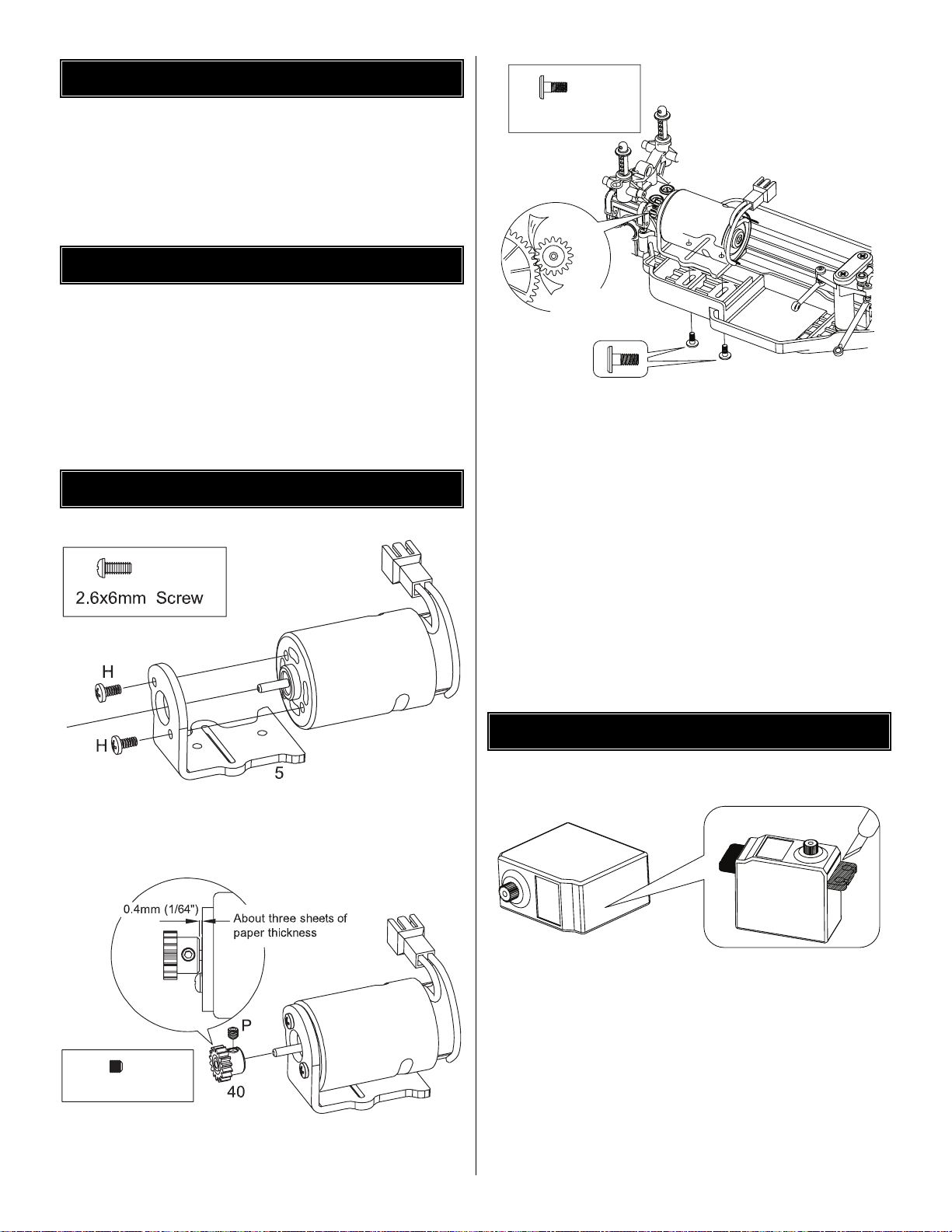
❏ 1. Using (2) 2.6x6mm (H) screws, secure your motor (not
included) onto the Mini Quake SE’s motor mount (5).
❏ 2. Install the included 16 tooth pinion (40) onto the motor
shaft and secure it to the motor shaft with a 3mm set screw (P).
❏ 3. Install the motor assembly onto the chassis (1).Secure
the motor mount (5) to the chassis using (2) 2.6x6mm (M)
screws. Before tightening the 2.6x6 screws, make sure the
gear mesh between the motor pinion (40) and the spur gear
(39) is set correctly.With a properly set gear mesh, you can
hold the pinion and still be able to slightly rock the spur gear
teeth back and forth in the pinion gear.Be careful not to set
the gear mesh too loose. It will cause the spur gear to strip.
Setting the gear mesh too tight will cause binding and could
damage your motor and speed control.
❏ 4. Once the gear mesh is properly set, tighten the
2.6x6mm (M) screws to secure the motor assembly in place.
❏ 1. For standard size servos, you will need to trim the
mounting tabs off the sides of the servo. TIP: Use Lexan
®
scissors to trim the mounting tabs from the servo. Carefully,
use a sharp hobby knife blade to clean up the remaining
portion of the mounting tab.
❏ 2. Locate the correct ser vo horn (30). There are multiple
servo horns included with the Mini Quake SE to fit different
brands of servos. NOTE: The correct servo horn should
slide on, without forcing it, onto the servo output shaft.
SERVO INSTALLATION
MOTOR INSTALLATION
ITEMS REQUIRED FOR COMPLETION
SPECIFICATION & DESCRIPTION CHANGES
3
x2 (H)
x2 (M)
2.6x6mm Screw
TIP: Sqeeze a piece
of paper to help set
the proper mesh.
With the proper mesh, you
should just be able to move
the gears independently. Too
tight will cause drag, too loose
and the gears will strip.
M
x1 (P)
3mm Set Screw
Trim off the tabs.
Standard
Servo
Page 4
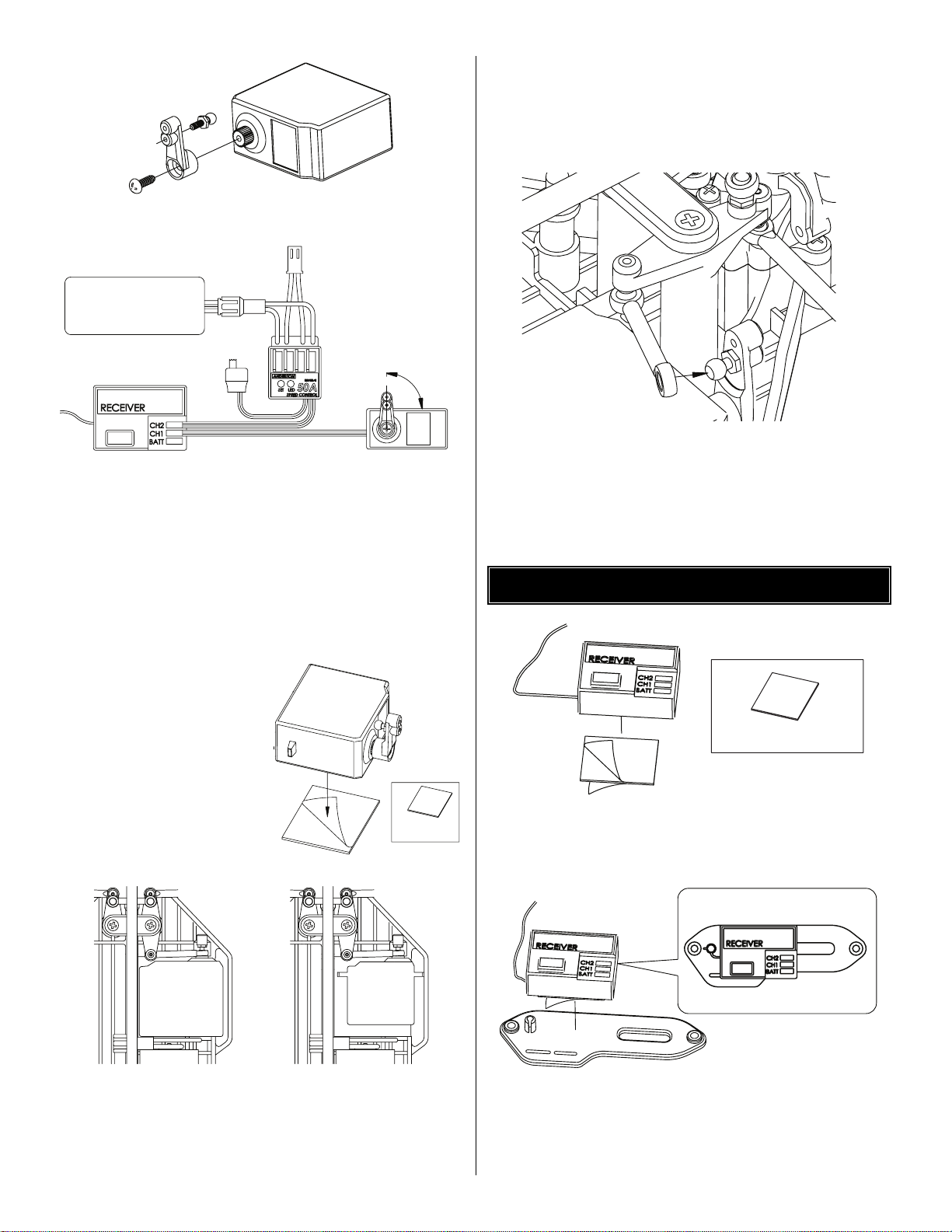
❏ 3. Install a 3.8mm ball (D) into the lower hole of the servo
horn (30) as shown in the drawing.
❏ 4.Center the trim of the servo.Y ou will need to hook up the
servo, receiver, speed control, and charged battery for this.
Center the trims on the transmitter.Then tur n the transmitter
on followed by the speed control. See your radio instructions
for location of the steering servo trim.
❏ 5. Make sure the servo is positioned properly (note the
output shaft orientation in the drawing) and install the servo
horn (30) onto the servo as shown. Secure the servo horn
(30) to the servo using the screw included with the servo.
❏ 6. Install the piece of
included double-sided tape
(S) onto the bottom of the
servo. TIP: Thoroughly clean
the bottom of the servo with
rubbing alcohol.This wiil help
ensure a good bond between
the servo and the doublesided tape.
❏ 7. Test fit the servo into the chassis so you know where it
needs to be mounted. Hold the servo in place and rotate the
steering back and forth.Make sure the linkage does not bind.
❏ 8. Remove the remaining protective backing from the
double-sided tape and install the servo into the chassis.TIP:
Thoroughly clean the chassis with rubbing alcohol. This wil
help ensure a good bond between the chassis and the
double-sided tape.
❏ 9. Attach the steering linkage connecting rod (31) to the
3.8mm ball (D) that was installed into the servo horn.
❏ 1. Install a piece of double-sided tape (S) onto the bottom
of your receiver. TIP: Thoroughly clean the receiver with
rubbing alcohol.
❏ 2. Install the receiver onto the wide portion of the battery
strap (42) as shown in the drawing.Make sure the receiver
is positioned so that the receiver antenna is pointing toward
the antenna mount. TIP: Thoroughly clean the receiver with
rubbing alcohol.
RECEIVER INSTALLATION
31
Standard servo
Micro servo
Typical steering
servo installation.
ON
7.2V BATTERY
90 deg
Center your servo with
your transmitter trims
before installing the servo
D
4
30
S
S
Double-Sided
Tape
S
Double-Sided Tape
S
42
Page 5
❏ 3.Run the receiver antenna wire through your fingers sever al
times to straighten it and then install it into the antenna tube
(43). A small amount of soapy water may also be used to help
get the antenna through the tube.
❏ 4. Leave a small amount of slack between the receiver
and the antenna mount and install the antenna tube (43)
into the antenna mount molded on the battery strap (42).
❏ 5. Secure the antenna to the antenna tube (43) using the
antenna cover (66).
❏ 1. Install a piece of double-sided tape (S) onto the bottom
of your speed control.
❏ 2. Remove the protective backing from the double-sided
tape and install the speed control onto the top of the servo
as shown in the drawing.
❏ 3. Make sure the wires are not too close to the drive shaft
(17).They could get caught in the shaft and become damaged.
❏ 4. Refer to the instructions that came with your speed
control for proper setup.
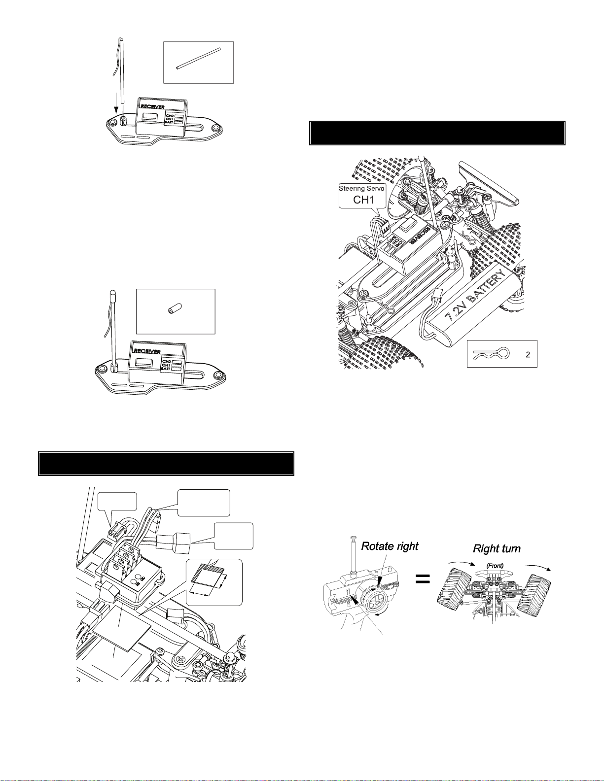
❏ 1. Remove the body clips from the battery holder and
insert the charged 6-cell batter y pack into the chassis.
❏ 2. Re-install the battery clips onto the batter y holder.
❏ 3.T urn the transmitter on, then the receiver.NOTE:Always
turn your transmitter on first. Gently pull back on the throttle
trigger.The Mini Quake SE should slowly move forward. If the
Mini Quake SE goes in reverse, move the throttle reversing
switch on the transmitter to the opposite position. After doing
this, the throttle trim may need to be adjusted to find the
throttle’s neutral point.See radio instructions.
❏ 4. Now, check that the steering reversing switch is set
properly.With the transmitter wheel facing you and the truck
facing away from you, turn the transmitter steering wheel to
the right. The wheels of the truck should turn so that when
the truck moves it will turn to the right. If it tur ns to the left,
the steering servo reversing switch needs to be moved to
the opposite position. After reversing the steering, the
steering trim on the transmitter may need to be adjusted to
center the steering of the truck.
FINISHING THE MINI QUAKE SE
23mm
23mm
Double Sided Tape
MOTOR
BATTERY
CH2
Speed Control
SPEED CONTROL INSTALLATION
Antenna Tube
IMPORTANT: Never cut the receiver antenna!
Doing so will severely reduce your range.
43
43
5
66
66
Antenna Cover
Page 6

The Mini Quake SE body comes clear. Below are a few tips
to follow when painting your Mini Quake SE body.
CAUTION:
• Always paint in a well-ventilated area.
• Never paint near an open flame.
❏ 1. Wash the inside of the body out with dish soap and
water.Make sure the body is thoroughly rinsed out.
❏ 2. Install the included window masks into the inside of the
body. Make sure the edges are well sealed to the body
to prevent leaks.
❏ 3. Use a quality masking tape or Hobbico
®
Liquid Mask to
mask the inside of the body off.
❏ 4.If using masking tape, make sure it is properly
sealed down.
❏ 5. If using Hobbico Liquid Mask, make sure to use
multiple coats.Make sure not to put the liquid mask on
too thick or too thin. 2-3 medium coats work best.
❏ 6. Use a new hobby b lade when cutting the masking tape
or liquid mask.
❏ 7. Paint the inside of the body using a quality Lexan
compatible paint. Spray dark colors first and always
back light colors with white or silver.
❏8.Decal the body as desired and install it onto the chassis,
securing it in place with the four included body clips.
For additional painting tips, please visit the f ollowing websites:
www.rccaraction.com/articles/htshake_1.asp
www.rctech.net/articles/painting_hauntedmyst.shtml
www.rcxotic.com/pkg-how/000002/index.shtml
BEFORE EACH RUN
• Make sure the batteries in the transmitter are charged.
• Mak e sure there are no loose or damaged parts on the kit.
• Check the drive train for binding that could cause
possible damage to the kit or the electronics.
• Check that the ESC and receiver are properly secured to
the chassis.
• Check to make sure all wires are properly secured.
AFTER EACH RUN
• Clean any large globs of dir t, carpet fuzz or any other
debris from the chassis.
• Disconnect and remov e the battery from the Mini Quake SE.
• Check for any broken or damaged parts. This way parts
may be replaced before the next run.
AFTER EVERY 10 RUNS
• Check to make sure the bearings are free of debris.
• Check for a smooth gear mesh.
• Check the tires to make sure they are still properly glued
to the wheels.
RIDE HEIGHT ADJUSTMENT
The ride height of the Mini Quake SE is easily adjusted by
using the included pre-load spacers (67). To increase the
ride height of the Mini Quake SE, install a pre-load spacer
onto each of the shock bodies between the spring and the
shock cap.The more pre-load clips you install, the more ride
height you will achieve. Make sure you install the same
amount of pre-load clips to each of the shocks.To lower the
ride height of the Mini Quake SE, remove the desired
amount of pre-load spacers from the shocks. TIP: Rough,
rocky surfaces require higher ride height; flat, smooth
surfaces allow a lower ride height.
PINIONS
The Mini Quake SE comes stock with the 16 tooth pinion.To
obtain higher top speeds you can install a larger pinion gear
onto the motor.This will, howe ver, decrease your acceleration
and run time. TIP: Smaller pinion equals more torque, less
top speed. Larger pinion equals more top speed, less torque.
SPURS
DuraTrax offers two different spur gear options for the Mini
Quake (a 45-tooth spur gear is included with the Mini Quake
SE): 40-Tooth (DTXC7409) and 49-Tooth (DTXC7432). The
40-tooth will give increased top speed, but decrease torque,
the 49-tooth will increase torque but decrease top speed.
SHOCK MOUNT LOCATION
There are three different lower shock mounting positions on
the Mini Quake SE. For jumping and climbing, the best
location is the inner most hole of suspension arm. This
makes the truck’s suspension feel softer. For racing and
surfaces with more traction, the best location is the outer
most hole.This location gives the truck’s suspension a stiff er
feel and allows less chassis roll in the corners.The middle
is a good all around location. Tip: Make sure the front
shocks are all in the same location and make sure all of the
rear shocks are all in the same location.They do not have to
be in the same location from front to rear.
SHOCK OIL
The Mini Quake SE comes stock with 25 weight oil in the
shocks.The handling of the tr uck can be tuned by changing
the shock oil to either heavier (bigger number) or lighter
(lower number .) By putting hea vier oil in the shocks , the truck
will have less chassis roll and become less responsive.
Putting lighter oil in the shocks will cause the truck to be
more responsive and hav e more chassis roll.For smooth, flat
surfaces, a thicker oil would be best. For surfaces that are
rough or have jumps, a lighter oil would be best.
SHOCK SPRINGS
DuraTrax offers three different shock springs: Soft (gray),
Medium/Stock (white) and Heavy (yellow). For rutted tracks
with small jumps, a soft spring should be used. For tracks
with large jumps, a heavy spring should be used to help
prevent chassis slap.
TUNING
RUNNING AND MAINTENANCE TIPS
P AINTING THE BOD Y
6
Page 7

❏1. Install a 6x10 bearing (61) onto the diff outdrive 1 (44).
❏2. Install diff outdrive 1 (44) into diff plate holder 1 (45).
❏3. Install a diff plate (46) onto the diff plate holder 1 (45).
❏4. Install a 4x7mm bearing (49) onto the diff plate holder
1 (45).Then install the differential main gear (47).
❏ 5. Apply grease to each of the 12 differential balls (48) and
install them into the differential main gear (47).
❏6. Install a second 4x7mm bear ing (49) onto the diff plate
holder (45).
❏7. Install the other differential plate (46) onto the
differential plate holder 2 (69).
❏8. Install a differential thrust plate (71) onto the differential
bolt (73).
❏9. Place a generous amount of diff grease (not included)
onto the differential thrust plates (71). Then install six
differential balls (48) onto the diff thrust plate (71).
❏10. Next install the second differential thrust plate (71)
onto the differential bolt (73).
❏11. Install a rubber spacer (70) onto the differential bolt
(73) and slide it up against the differential plate (71).
❏ 12. Apply threadlocking compound on the diff bolt (73)
threads and install the diff bolt into the diff plate holder (69).
❏ 13. Carefully install the diff outdr ive inner side 2 (75) onto
the diff plate holder side 2.Note:This will hold the thrust
balls in place when you tighten the differential bolt.
❏ 14. Install a 6x10mm bearing (61) onto the diff outdrive
outer side 2 (75). Then install the diff outdrive outer (75)
into the diff outdrive inner (74).Secure the pieces together
by installing a 5mm E-clip (C).
Using a 1.5mm hex wrench, gently tighten the differential bolt
(73). Tighten the bolt until it becomes snug.Then back it off
1/16 of a turn. Note: Do not over tighten the bolt. It could
damage the differential balls and differential plates.The
differential bolt may need to be tightened after the first
couple of runs.This is due to the par ts wearing in.
You can use the adjustable ball diffs to tune your truck’s
handling. Tightening the ball diff will increase forward
traction, but decrease cornering. TIP: Be sure not to
overtighten or loosen the ball diff.Ov ertightening will put flat
spots on the balls, causing excess drag. Too loose of a
setting will make the differential slip and overheat.
BALL DIFFERENTIAL TUNING
BALL DIFFERENTIAL ASSEMBLY
7
ASSEMBLY GUIDE
Page 8

8
Apply ball diff grease
Using a 1.5mm hex wrench, gently tighten the differential bolt (73) until it
becomes snug.Then back it off 1/16 of a turn.
Note: Do not overtighten the bolt. It could damage the differential balls and
differential plates. The differential bolt may need to be tightened after the
first couple of runs.This is due to parts wearing in.
Page 9

9
Page 10

10
3.8mm Ball Stud
3.8mm Ball Stud
4x7mm Bushing
Page 11

11
Page 12

12
Tip: Squeeze a piece
of paper to help set
the proper mesh.
Page 13

131415
Page 14

Page 15

Page 16

163517
Page 17

SET
LED
Apply CA glue to the inside
of both the rim and the tire.
Page 18

18
S
Double Sided
Tape
Page 19

19
Page 20

OTHER ITEMS AVAILABLE FROM DURATRAX
DTXC2377
Kwik Trak Racing Cones
DTXQ0100
Metric Phillips Head Screw Set
DTXR0140 Screwdriver Set
DTXC2375
Kwik Ramp Portable Jump
Pit Tech Mini Car Stand
DTXC2361 Blue
DTXC2362 Orange
DTXC2363 Purple
DTXC2364 Green
DTXR0183 Ultimate Drivers
Phillips Screwdriver
DTXR0292 Ultimate Drivers
Metric Hex Drivers
DTXP2040 Vinyl W ork Mat
DTXC2459
Power Shot Motor Cleaner
DTXP2015
Transmitter Bag
DTXC8279
Motor Heatsink Blue
DTXC6997
Graphite Chassis
 Loading...