

Duke FLEXIBLE BATCH BROILER, FBB-NO-120, FBB-NC-120, FBB-PO-120, FBB-PC-120 Installation & Operation Manual
Installation & Operation Manual
FLEXIBLE BATCH BROILER
800-735-3853 • 314-231-1130 • Fax 314-231-5074
Duke Manufacturing Co.
2305 N. Broadway • St. Louis, Missouri
www.dukemfg.com
175500E

FLEXIBLE BATCH BROILER
RESTAURANT
Revised:
35
INDEX
I. General Information ..........................................................................4
A. Batch Broiler Specifications................................................................................. 4
A-1.0 Model Number Key .................................................................................. 5
A-2.0 Broiler Dimensions ................................................................................... 5
II. Installation Instructions....................................................................6
A. Qualified Personnel ...........................................................................................6
B. Delivery and Inspection .....................................................................................7
C. Broiler Assembly................................................................................................ 8
D. Adjustments at Installation…………………………………………………………..9
E. Location of the Broiler........................................................................................ 10
F. Gas Piping ......................................................................................................... 10
G. Electrical Connections....................................................................................... 11
H Ventilation.......................................................................................................... 11
III. Operation Instructions.....................................................................12
A. Broiler Controls .................................................................................................. 12
B. Cooking Product ................................................................................................ 13
B-1.0 Lighting the Broiler ................................................................................... 13
B-2.0 Cook Product ........................................................................................... 13
B-3.0 Cook Cycle Complete .............................................................................. 14
B-4.0 Fine Cooking Adjustment......................................................................... 14
B-5.0 Cancel a Cook Cycle ............................................................................... 14
B-6.0 Checking the Broiler Temperature........................................................... 14
B-7.0 Checking the Set Point Temperature....................................................... 14
B-8.0 Shutdown the Broiler................................................................................ 14
C. Cleaning............................................................................................................. 15
C-1.0 Four (4) Hour Cleaning ........................................................................... 16
C-2.0 Daily Cleaning.......................................................................................... 17-19
C-3.0 Weekly Cleaning ...................................................................................... 19-23
D. Programming the Control ..................................................................................24
D-1.0 Entering Program Mode .......................................................................... 24
D-2.0 Navigating the Programming Screens..................................................... 24
D-3.0 Level 1 Programming............................................................................... 24
D-3.1 Product Identifier...................................................................................... 25
D-3.2 Cook Temperature................................................................................... 25
D-3.3 Cooking Profile ........................................................................................ 25
D-3.4 Exit Program Mode .................................................................................. 25
D-4.0 Level 2 Programming............................................................................... 25
D-4.1 F or C Parameter ..................................................................................... 25
D-4.2 Change the Idle Temperature.................................................................. 25
D-4.3 Additional Factory Parameters ................................................................ 25
D-4.4 Exit Program Mode .................................................................................. 25
EQUIPMENT
MANUAL
PAGE
April 1, 2007
2 of 35

FLEXIBLE BATCH BROILER
RESTAURANT
Revised:
E. Troubleshooting ................................................................................................. 26-29
35
IV. Service and Repair ..........................................................................30
A-1.0 Warnings ........................................................................................................ 30
V. Replacement Parts List ...................................................................31-33
VI. Wiring diagram.................................................................................34
VII. Customer Assistance .....................................................................35
EQUIPMENT
MANUAL
PAGE
April 1, 2007
3 of 35

FLEXIBLE BATCH BROILER
RESTAURANT
Revised:
35
EQUIPMENT
MANUAL
POST IN A PROMINENT LOCATION
the event the user smells gas. This information shall be obtained by consulting
Do not store or use gasoline or other flammable vapors or liquids in the vicinity of
Improper installation, adjustment, alteration, service or maintenance can cause
property damage, injury or death. Read the installation, operating and maintenance
instructions thoroughly before installing or servicing this equipment.
THIS MANUAL MUST BE RETAINED FOR FUTURE REFERENCE.
I. General Information
A. Batch Broiler Specifications
instructions to be followed in
the local gas supplier.
FOR YOUR SAFETY:
this or any other appliance.
WARNING:
FLEXIBLE BATCH BROILER SPECIFICATIONS
ALTITUDE (MAXIMUM)
GAS PIPE CONNECTION
INLET PRESSURE RANGE
MANIFOLD PRESSURE MANIFOLD PRESSURE
INFRARED BURNERS (TOP)
LOWER BURNER
TOTAL ENERGY RATE
BURNER ORIFICE SIZE BURNER ORIFICE SIZE
FRONT INFRARED BURNER
BACK INFRARED BURNER
LOWER BURNER
NATURAL GAS PROPANE
2000 FT 607 m 2000 FT 607 m
3/4 “ F-NPT 3/4” F-NPT
7” – 12” W.C. 10” – 12” W.C.
3.75” W.C. 0.93 kPa 8.0” W.C. 2.0kPa
3.75” W.C. 0.93 kPa 8.” W.C. 2.0kPa
87000 – 111,000
BTU/HR
#40 2.49mm #52 1.61mm
#36 2.70mm #51 1.70mm
#31 2.05mm #49 1.85mm
25.5 – 32.5
kW
79,000 –
105,000 BTU/HR
23.2 – 30.7
kW
April 1, 2007
4 of 35
FLEXIBLE BATCH BROILER
RESTAURANT
Revised:
35
EQUIPMENT
MANUAL
A. Batch Broiler Specifications (cont’d)
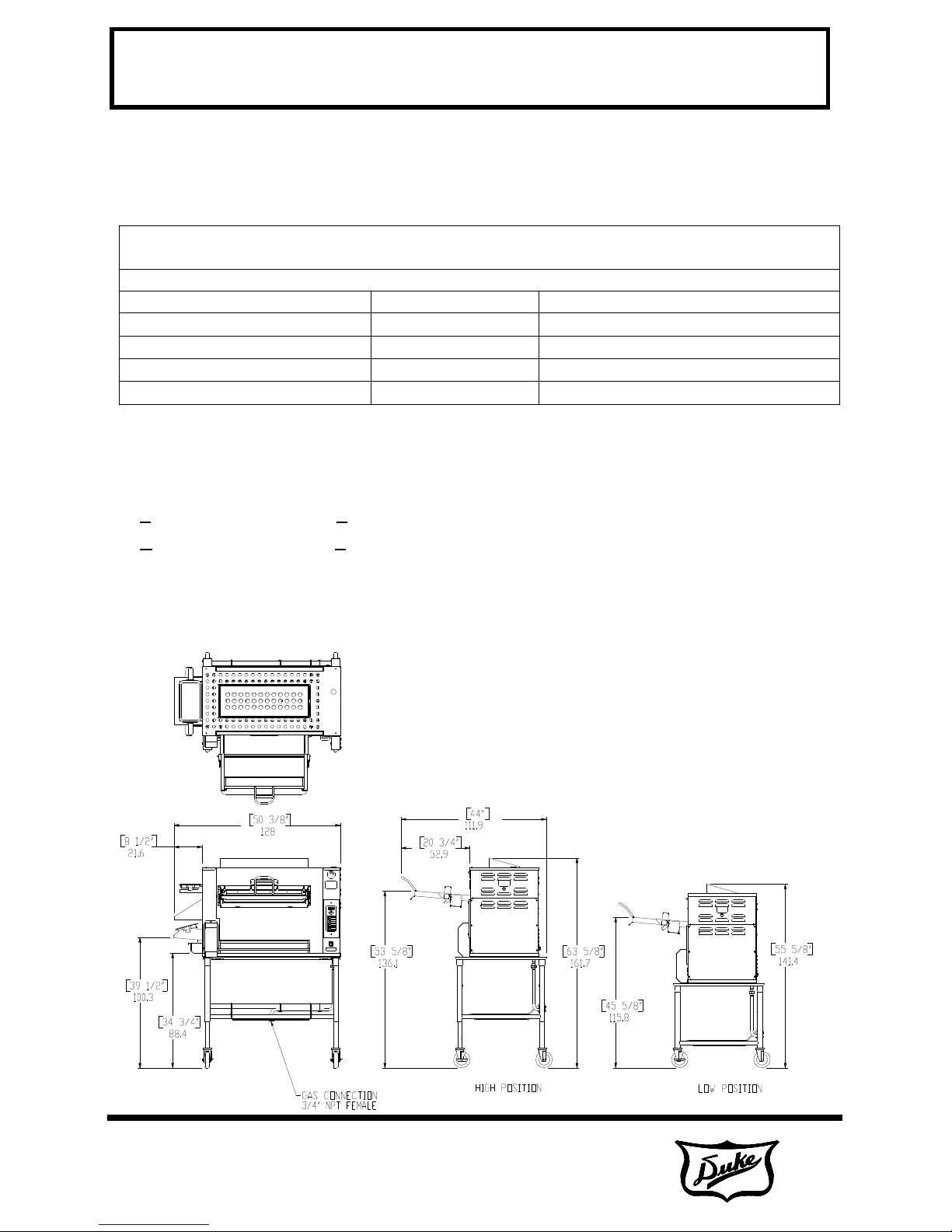
SHIPPING WEIGHT: 450 lbs (204 Kg)
SHIPPING DIMENSIONS: 48” x 39” x 68” (121.9 x 99.1 x 172.7 cm)
MODEL NUMBER ELECTRIC NATURAL & LP GAS
FBB-NO-120 120VAC, 2A, 60Hz 87,000 – 111,000 BTU/HR
FBB-NC-120 120VAC, 2A, 60Hz 87,000 – 111,000 BTU/HR
FBB-PO-120 120VAC, 2A, 60Hz 79,000 – 105,000 BTU/HR
FBB-PC-120 120VAC, 2A, 60Hz 79,000 – 105,000 BTU/HR
A-1.0 Model Number Key
FBB-X Y -120
X = N (NATURAL GAS) OR P (PROPANE / LP GAS)
Y = O (NO CATALYST) OR C (CATALYST)
120 = 120 VOLTS
A-2.0 Broiler Dimensions
April 1, 2007
5 of 35

FLEXIBLE BATCH BROILER
RESTAURANT
Revised:
35
EQUIPMENT
MANUAL
II. Installation Instructions
A. Qualified Personnel
These installation instructions are for the use of
qualified installation and service personnel
only. Installation or service by other than
qualified personnel may result in damage to the
broiler and/or injury to the operator.
Qualified installation personnel are those
individuals, firms, companies or corporations
which either in person or through an agent is
engaged in and responsible for:
•The installation or replacement of gas piping
or the connection, installation, repair or
servicing of equipment, who are experienced
in such work, familiar with all precautions
required, and have complied with all
requirements of state and local authorities
having jurisdiction. See: National Fuel Gas
Code NFPA 54 (ANSI Z223.1).
•The installation of electrical wiring from the
electric meter, main control box or service
outlet to the electrical appliance. Qualified
installation personnel must be familiar with all
precautions required and have complied with
all requirements of state and local authorities
having jurisdiction. See: National Electrical
Code, ANSI/NFPA70.
installing the broiler with casters and quickdisconnect hose, adequate means must be
provided to limit the movement of the broiler
without depending on the connector and the
quick disconnect device or its associated piping
to limit the broiler movement. A means for
restraining may be attached to the vertical
portion of the base frame in the rear of the
broiler.
The installation must conform with local codes, or
in the absence of local codes, with the National
Fuel Gas Code, ANSI Z223.1/NFPA 54, or the
Natural Gas and Propane Installation Code, CSA
B149.1 as applicable, including:
•The appliance and its individual shutoff
valve must be disconnected from the gas
supply piping system during any pressure
testing of that system at test pressures in
excess of ½ psi (3.5 kPa).
•The appliance must be isolated from the gas
supply piping system by closing its individual
manual shutoff valve during any pressure
testing of the gas supply piping system at test
pressures equal to or less than ½ psi (3.5
kPa).
For a broiler mounted on casters, the installation
shall be made with a connector that complies with
the Standard for Connectors for Movable Gas
Appliances, ANSI Z21.69/CSA 6.16 and a quickdisconnect device that complies with the
Standard for Quick-Disconnect Devices for Use
with Gas Fuel, ANSI Z21.4/CSA 6.9. When
April 1, 2007
6 of 35
FLEXIBLE BATCH BROILER
RESTAURANT
Revised:
35
EQUIPMENT
MANUAL
B. Delivery and Inspection
Duke Manufacturing Co. does everything within
its power to insure you received your broiler in
good condition. They are strapped down on
heavy wooden skids and packed to prevent
shipping damage. They have all been carefully
inspected before they were packaged and
consigned to the carrier.
Upon delivery of your Duke broiler:
• Look over the shipping container, carefully
noting any exterior damage on the
delivery receipt, which must also be
signed by the driver/ delivery person.
• Unpack and check for any damage, which
was not evident on the outside of the
shipping container.
3
2
4
• Check for concealed damage. The carrier
must be notified within fifteen (15) days
of the delivery of the broiler and the
carton, skid and all packaging materials
must be retained for inspection.
Duke Manufacturing Co. cannot assume liability
for loss or damage suffered in transit. The
carrier assumes full responsibility for delivery in
good order when the shipment was accepted.
However, we are prepared to assist you in filing
your claim.
3
4
3
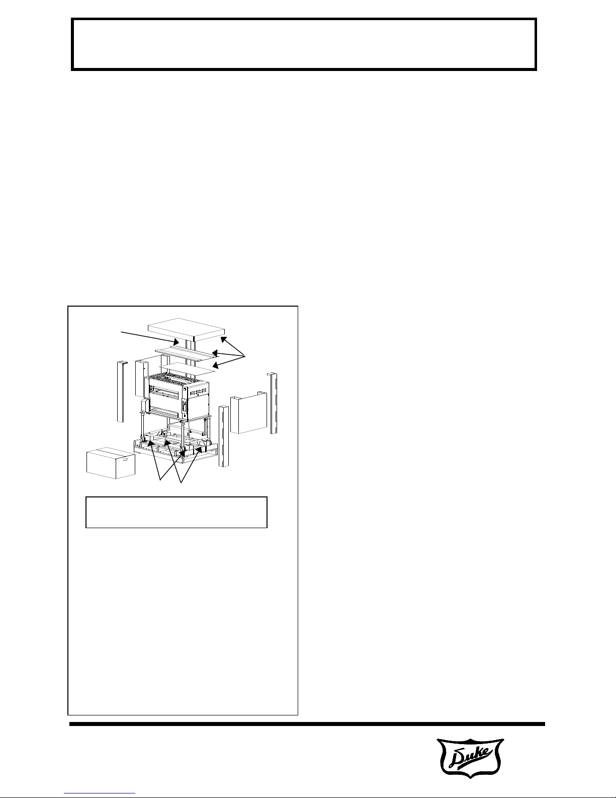
1) Using a utility knife, cut away plastic wrap (Not shown).
2) Remove the top cardboard and inner cap.
3) Remove cardboard from the corners (4 places).
4) Remove cardboard on the ends (2 places).
5) Remove banding straps (Cut with utility knife or scissors: 5
6) Remove box of attachable parts & accessories from the
7) Safely lift one end of broiler and tap block towards center
8) Remove the broiler from the shipping pallet using 3 people
9) Remove protective blue tape from broiler panels, double
6
7
5
Caution: The Broiler is very heavy!
Use adequate help for lifting.
places).
front.
and then sideways to remove. Repeat for remaining
blocks. This allows casters to touch the pallet.
to guide and distribute it’s weight (approx 335 lbs)
accordingly. While carefully supporting the broiler. Roll it
forward until the front casters are clear of the pallet. Lift
the broiler 6-8 inches above and away from the pallet, and
gently place on floor to avoid damage to casters.
checking that no tape remains.
3
April 1, 2007
7 of 35
FLEXIBLE BATCH BROILER
RESTAURANT
Revised:
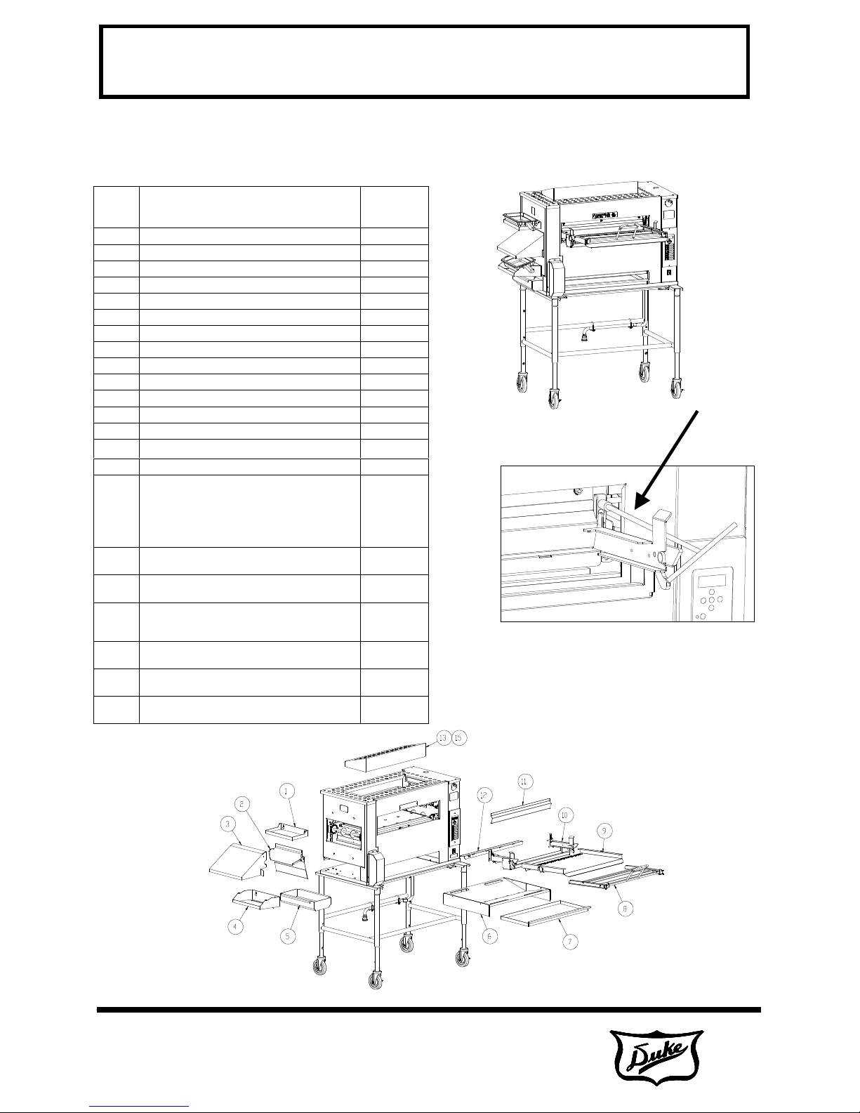
20 nuts.
Use supplied extension tool to remove
and reinstall nuts. (Nuts are shipped
35
EQUIPMENT
MANUAL
C. Broiler Assembly
Before assembling and installing the broiler,
please check to make sure that all necessary
parts are present.
Item # Part Name Part
Number
1 PRODUCT PAN SHELF 175353
2 DISCHARGE CHUTE 175340
3 DISCHARGE HOOD 175362
4 DISCHARGE PAN HOLDER 175358
5 DISCHARGE GREASE PAN 175357
6 “V” GREASE PAN 175325
7 MAIN GREASE PAN 175329
8 LOADER 175444
9 LOADER TRAY 175430
10 LOADER BRACKET 175438
11 DOOR 175429
12 LOADER RAMP 175741
13 IMPEDANCE PAN 175226
14 CATALYST (OPTIONAL) 175480
15 CATALYST GUARD (OPTIONAL) 175482
16 KIT, CLEANING TOOLS/INSTALLATION
TOOL CLEANING – LOWER BURNER
FLAME ROD TUBE CLEANER
BRUSH, TUBE CLEANER
TOOL-LOADER INSTALL
WRENCH, ALLEN, 3/16”
17 KIT – BROILER SVC. PARTS, NAT. GAS W/
CONTROLLER W/COOK CHAIN (OPTIONAL)
18 KIT – BROILER SVC. PARTS, PROPANE, W/
CONTROLLER W/COOK CHAIN (OPTIONAL)
19 KIT – USER REPLACEABLE, BOTTOM
BURNER, FLAME ARRESTOR, LOADER &
BURNER SHIELD (OPTIONAL)
20 KIT – USER REPLACEABLE, BOTTOM
BURNER & FLAME ARRESTOR (OPTIONAL)
21 KIT – GAS HOSE CONNECTOR ASSEMBLY
(OPTIONAL)
22 KIT – HIGH SUPPLY GAS PRESSURE
REGULATOR (OPTIONAL)
175700
175725
175740
175726
175750
175690
175689
Setup
Install all items as shown below.
Loader Install Tool
(Included with
Broiler Tools Kit)
Install loader bracket with (4) ¼-
installed on loader mounting studs.)
April 1, 2007
8 of 35
FLEXIBLE BATCH BROILER
RESTAURANT
Revised:
35
EQUIPMENT
MANUAL
D. Adjustments at Installation
Each broiler section and all its component parts
have been tested thoroughly and inspected
before your broiler was shipped from the factory.
However, it is sometimes necessary to further
test or adjust the broiler once it has been
installed. Such adjustments are the responsibility
of the Dealer or Installer. These types of
adjustments are not considered defects, rather a
normal and routine part of the proper installation
of the equipment.
These adjustments include but are not limited to:
• Adjustments to the gas pressure regulator
• Broiler height adjustment (if required)
No installation should be considered complete
without proper inspection and, if necessary, any
adjustments by qualified service or installation
personnel.
It is also important not to obstruct the natural flow
of combustion and ventilation air if the broiler is to
operate properly. This broiler should not be
installed on a curb base or sealed to the wall.
Either condition can restrict the flow of air to the
combustion compartment or prevent proper
ventilation of the unit. Before making any
connections to the broiler, check the ratings plate
to be sure the broiler specifications concur with
the type of gas and voltage to be supplied to the
broiler.
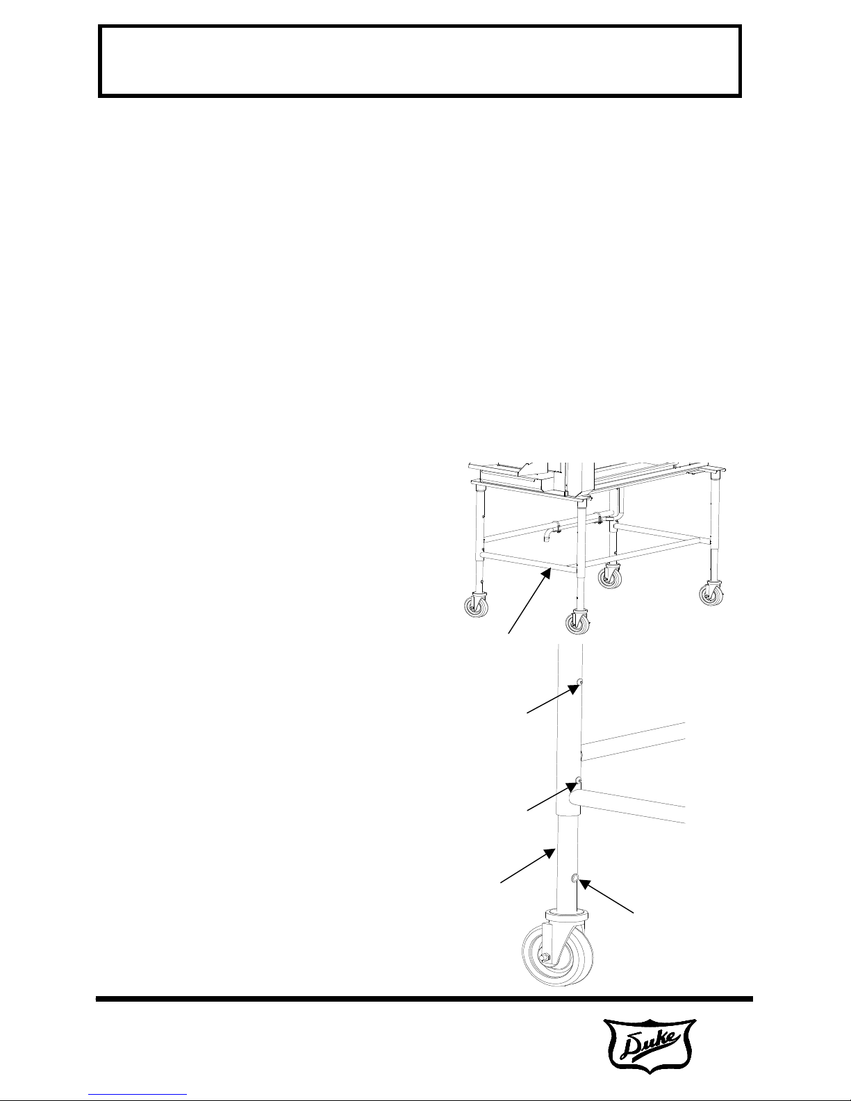
Raise or Lower Broiler
The broiler height can be adjusted via two
screws on each leg.
Caution: The Broiler is very heavy! Use
adequate help for lifting.
1. Lift one end of the broiler onto a wide,
sturdy stand (not supplied).
2. Remove (2) screws per leg and
raise/lower to threaded holes. Reinstall
screws.
3. Remove stand and safely raise/lower
broiler.
4. Place plastic hole plugs (supplied attach
to stand) in any unused holes.
Support broiler here
The rating plate is located on the back of the
control compartment cover panel on the right end
of the unit.
The plate bearing the broiler’s model number and
serial number is attached to the back side of the
unit.
April 1, 2007
9 of 35
Screw
Screw
Slide Leg.
Reinstall screws.
Plastic Hole
Plug

FLEXIBLE BATCH BROILER
RESTAURANT
Revised:
NOTE: A fixed restraint of the proper length must be
movable
surface to eliminate strain on the gas connector. If the
mal position, the
35
E. Location of the Broiler
Proper planning and placement of the broiler will
give you the best results in terms of long-term
user convenience and satisfactory performance.
We urge you to give adequate thought in the
placement of your broiler prior to its arrival.
•The broiler should be placed in an area that
is free from drafts and accessible for proper
operation and servicing.
•The area around the broiler must be kept
clear of combustible materials. A minimum
clearance of:
Discharge End
Access Panel End
Rear
Floor/Table
Combustible
12" (305) 12” (305)
3" (76) 3” (76)
4" (102) 4” (102)
0" (0) 0” (0)
Non-
Combustible
EQUIPMENT
MANUAL
F. Gas Piping
The standard broiler consumes gas at a total of
100,000 BTU/hr. In order to achieve the degree
of performance for which the unit has been
designed, the overall piping plan of the kitchen,
properly sized, is essential. The installation of
this broiler must conform with all local codes, or
in the absence of any local codes, to the
National Fuel Gas Code, NFPA 54 and ANSI Z
223.1.
Your local gas supplier should consult the
National Fuel Gas Code for proper sizing and
installation of gas piping. Generally, piping should
be sized to provide a gas supply sufficient to
meet the maximum demand of all gas appliances
on a line without undue loss of pressure at the
outlet to the equipment. The total BTU
requirements of the equipment being served and
the length of the piping from the meter to the
appliances are major considerations in the proper
design of the gas supply system.
NOTICE TO INSTALLER:
NATURAL GAS UNIT ONLY
THIS APPLIANCE SHALL BE CONNECTED TO A GAS
SUPPLY IN THE RANGE OF 7” TO 12” W.C.
Gas supply pressure must be checked prior to
installation. If supply pressure is in excess of 12” W.C.,
The HIGH SUPPLY PRESSURE KIT, Duke P/N 175689
shall be installed and adjusted, per kit instructions, for an
incorporated to secure the broiler to a non-
broiler is removed from its nor
restraint must then be reattached when returned.
April 1, 2007
10 of 35

FLEXIBLE BATCH BROILER
RESTAURANT
Revised:
35
EQUIPMENT
MANUAL
G. Electrical Connections
Your broiler is supplied for connection to a
dedicated 120 volt, grounded circuit. The electric
motors, indicator lights and control circuits are
connected through a seven-foot electric supply
cord found at the rear of the broiler.
Before making any connections to these units,
check the rating plate to assure that the voltage
and phase of the broiler is compatible with the
electrical supply. When installing, all broilers must
be electrically grounded in accordance with local
codes, or in the absence of local codes, with the
National Electrical Code, ANSI/NFPA 70 (in
Canada - CSA Std. C22.2). Wiring diagrams are
located in the control compartment area of the
broiler. Standard wiring schematics are also
provided with this manual.
WARNING: This appliance is equipped with a
three-prong (grounding) plug for your
protection against shock hazard and should
be plugged directly into a properly grounded
three-prong receptacle. DO NOT cut or
otherwise remove the grounding prong from
this plug.
This inspection/maintenance should consist of,
but not be limited to:
• Inspection for blockages or build up
which might interfere with the venting of
the broiler.
• Repair of such blockages.
• Inspection of the venting canopy, its
drive motors and bells, etc.
Do not place any objects such as
sheet pans, food containers or
aluminum foil on the top of the
broiler. This will obstruct the venting
of cooking vapors and airflow
through the unit—resulting in poor
cooking performance.
H. Ventilation
This is a gas broiler. Improper ventilation is can
cause serious illness or death. A good
ventilation system will also allow the broiler to
function properly. To keep your warranty in force,
a proper ventilation system must be employed.
Venting to a Canopy Exhaust Hood
The best way to vent your broiler is by placing it
under a properly designed mechanically driven
exhaust hood. The hood should have adequate
capacity and provide a sufficient supply of makeup air. Ventilation hoods come in many sizes and
capacities. Hood capacity is expressed in cubic
feet per minute (CFM). Information for the proper
construction and installation of ventilating hoods
may be obtained from the "Standard for the
Installation of Equipment for the Removal of
Smoke and Grease-Laden Vapors from
Commercial Cooking Equipment, NFPA-96".
Maintenance of Ventilation System
It is important that the ventilation system be
inspected and/or maintained by Qualified
Personnel at least once each year.
April 1, 2007
11 of 35
 Loading...