

Duke FBB-EC-208 Service Manual
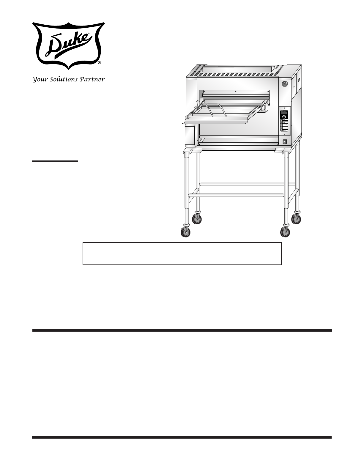
FLEXIBLE BATCH
BROILER
MODELS
FBB-EO-208
FBB-EC-208
FBB-EO-230
Service Manual
FBB-EC-230
FBB-EO-240
FBB-EC-240
This document is prepared for trained Duke service technicians. It is not to be used by anyone not
properly qualied to perform these procedures.
This Service Manual is not all encompassing. If you have not been trained on servicing this product,
be sure to read the manual completely before attempting servicing. Be sure all necessary tools,
test equipment, and skills are available. Those procedures for which you do not have the proper
skills and test equipment must be performed only by a qualied Duke trained service technician.
This manual is Copyright © 2010 Duke Manufacturing Co. All rights reserved.
Reproduction without written permission is prohibited. Duke is a registered
Please read this manual completely before attempting
to install, operate or service this equipment
trademark of the Duke Manufacturing Co.
Duke Manufacturing Co.
2305 N. Broadway
St. Louis, MO 63102
Phone: 314-231-1130
Toll Free: 1-800-735-3853
Fax: 314-231-5074
www.dukemfg.com
P/N 177769A

Service Manual for Flexible Batch Broiler Units
IMPORTANT WARNING AND SAFETY INFORMATION
THIS MANUAL HAS BEEN PREPARED FOR PERSONNEL QUALIFIED TO INSTALL
ELECTRICAL EQUIPMENT, WHO SHOULD PERFORM THE INITIAL FIELD START-
UP AND ADJUSTMENTS OF THE EQUIPMENT COVERED BY THIS MANUAL.
READ THIS MANUAL THOROUGHLY BEFORE OPERATING, INSTALLING OR
PERFORMING MAINTENANCE ON THE EQUIPMENT.
Failure to follow all the instructions in this manual can cause property damage,
injury or death.
Improper installation, adjustment, alteration, service or maintenance can
cause property damage, injury or death.
Electrical connections should
be performed only by a certied professional.
Electrical and grounding connections must comply with the applicable portions of the National Electric Code and/or all
local electric codes. Failure to comply with this
procedure can cause property damage, injury or
death.
Before connecting the unit to
the electrical supply, verify that the electrical and
grounding connections comply with the applicable portions of the National Electric Code and/
or other local electrical codes. Failure to comply
with this procedure can cause property damage,
injury or death.
Before connecting the unit to
the electrical supply, verify that the electrical
connection agrees with the specications on the
data plate. Failure to comply with this procedure
can cause property damage, injury or death.
UL73 grounding instructions: This appliance must be connected to a
grounded, metal, permanent wiring system. Or
an equipment-grounding conductor must be run
with the circuit conductors and connected to
the equipment-grounding terminal or lead on the
appliance. Failure to comply with this procedure
can cause property damage, injury or death.
Appliances equipped with a
exible electric supply cord, are provided with a
grounding plug. It is imperative that this plug be
connected into a properly grounded receptacle.
Failure to comply with this procedure can cause
property damage, injury or death.
If the receptacle is not the
proper grounding type, contact an electrician. Do
not remove the grounding prong from the plug.
Failure to comply with this procedure can cause
property damage, injury or death.
Before performing any service
that involves electrical connection or disconnection and/or exposure to electrical components,
always perform the Electrical LOCKOUT/TAGOUT Procedure. Disconnect all circuits. Failure
to comply with this procedure can cause property damage, injury or death.
Before removing any sheet
metal panels or servicing this equipment, always perform the Electrical LOCKOUT/TAGOUT
Procedure. Be sure all circuits are disconnected.
Failure to comply with this procedure can cause
property damage, injury or death.
Do not operate this equipment
without properly placing and securing all covers
and access panels. Failure to comply with this
procedure can cause property damage, injury or
death.
Do not use or store gasoline or
other ammable vapors or liquids in the vicinity
of this or any other appliance. Failure to comply
can cause property damage, injury or death.
In the event of a power failure,
do not attempt to operate this appliance. Failure
to comply can cause property damage, injury or
death.
2

Service Manual for Flexible Batch Broiler Units
TABLE OF CONTENTS
INTRODUCTION ..................................................................................................................................5
INSTALLATION ...............................................................................................................................5
OPERATION ...................................................................................................................................5
CLEANING .....................................................................................................................................5
SPECIFICATIONS ................................................................................................................................6
MODEL NUMBER KEY ..................................................................................................................6
TOOLS............................................................................................................................................6
REMOVAL AND REPLACEMENT OF COMPONENTS .......................................................................7
COVERS AND PANELS .................................................................................................................7
Fuse Access Panel ...................................................................................................................7
Element Connection Access Panel ...........................................................................................7
Electrical Access Panel .............................................................................................................7
Product Pan Shelf .....................................................................................................................8
Discharge Hood ........................................................................................................................8
Discharge Chute .......................................................................................................................8
Discharge Pan ..........................................................................................................................8
Discharge Grease Pan .............................................................................................................9
Discharge Access Panel ...........................................................................................................9
Main Grease Pan ....................................................................................................................10
Grease V-Pan .........................................................................................................................10
Loader Tray .............................................................................................................................10
Conveyor Drive Motor Cover ..................................................................................................11
Top Service Panel ...................................................................................................................11
Removing the Front Panel ......................................................................................................12
Removing the Rear Panel .......................................................................................................12
Removing the Element Cover Panel .......................................................................................12
COMPONENT REMOVAL ............................................................................................................13
Conveyor Drive Motor Assembly ............................................................................................13
Conveyor Drive Chain .......................................................................................................14
Conveyor Drive Motor Sprocket ........................................................................................14
Conveyor Drive Motor Capacitor ......................................................................................15
Cook Chamber Temperature Probe ........................................................................................16
Control Board ..........................................................................................................................17
Step-Down Transformer ..........................................................................................................17
Solid-State Relays ..................................................................................................................18
Main Power Switch .................................................................................................................18
Mechanical Relays ..................................................................................................................19
Replacing Conveyor Links ......................................................................................................19
HEATING ELEMENTS..................................................................................................................20
FUSE REPLACEMENT ................................................................................................................22
ADJUSTMENTS .................................................................................................................................23
DRIVE CHAIN DEFLECTION ADJUSTMENT ..............................................................................23
CONVEYOR POSITION ADJUSTMENT ......................................................................................23
ASH SCRAPER BRACKET ADJUSTMENT .................................................................................24
LOADER DOOR SEAL BRACKET ...............................................................................................24
PRODUCT STOP BRACKET ADJUSTMENT ..............................................................................25
3

Service Manual for Flexible Batch Broiler Units
SEQUENCE OF OPERATION .......................................................................................................... 26
TROUBLESHOOTING .......................................................................................................................27
COMPONENT CHECK PROCEDURES ......................................................................................27
Checking the Power Switch ....................................................................................................27
Checking the Control Board ....................................................................................................27
Testing the Temperature Probe ...............................................................................................27
Checking the Conveyor Drive Motor .......................................................................................27
Testing the Conveyor Drive Motor ..........................................................................................28
Checking Conveyor Drive Motor Capacitor ............................................................................28
Testing the Relays ..................................................................................................................28
Testing the Transformers ........................................................................................................29
Voltage Test ......................................................................................................................29
Resistance Check .............................................................................................................29
Testing the Mechanical Relays ...............................................................................................29
Continuity Test ..................................................................................................................29
Testing the Contactors ............................................................................................................29
Voltage Test ......................................................................................................................29
CONTROL DIAGNOSTICS ..........................................................................................................30
Programming ..........................................................................................................................30
Diagnostics .............................................................................................................................30
TROUBLESHOOTING CHART ....................................................................................................32
PREVENTIVE MAINTENANCE ..........................................................................................................35
ELECTRICAL SCHEMATIC – FLEXIBLE BATCH BROILER .............................................................36
CUSTOMER ASSISTANCE ................................................................................................................39
4

Service Manual for Flexible Batch Broiler Units
INTRODUCTION
INSTALLATION
For detailed installation instructions, refer to the
Installation and Operation Manual.
OPERATION
For specic operating instructions, refer to the
Installation and Operation Manual.
CLEANING
For specic cleaning instructions, refer to the
Installation and Operation Manual.
5

Service Manual for Flexible Batch Broiler Units
SPECIFICATIONS
ELECTRICAL
MODEL NUMBER VOLTAGE AMPS CYCLE
FBB-EO-208 208 68 60 3 23.5 kW NO
FBB-EC-208 208 68 60 3 23.5 kW YES
FBB-EO-230 230 62 60 3 23.5 kW NO
FBB-EC-230 230 62 60 3 23.5 kW YES
FBB-EO-240 240 60 50 3 23.5 kW NO
FBB-EC-240 240 60 50 3 23.5 kW YES
PHASE POWER CATALYST
SHIPPING
WEIGHT
BATCH BROILER
(STANDARD)
SHIPPING
DIMENSIONS
L X W X H 47" X 34" X 68" 119.4 X 86.4 X 172.7
lbs Kg
530 240
Standard Metric (cm)
MODEL NUMBER KEY
FBB–EX-Y-ZZ
X = O (No Catalyst) or C (Catalyst)
Y = 208 VAC, 230 VAC or 240 VAC
ZZ = 2 Digit Country Identier
TOOLS
STANDARD
• Standard set of hand tools.
• Volt-Ohm Meter (VOM) with AC current
clamp
(Any quality VOM with a sensitivity of at
least 20,000 ohms per volt can be used).
• Conveyor Link Removal Pliers
6
Service Manual for Flexible Batch Broiler Units
REMOVAL AND REPLACEMENT OF COMPONENTS
COVERS AND PANELS
WARNING
DISCONNECT THE ELECTRICAL
POWER TO THE BROILER AND
FOLLOW LOCKOUT / TAGOUT
PROCEDURES.
Caution: If the broiler has been operating,
broiler panels and components
may be hot. Use PROPER
PROTECTION.
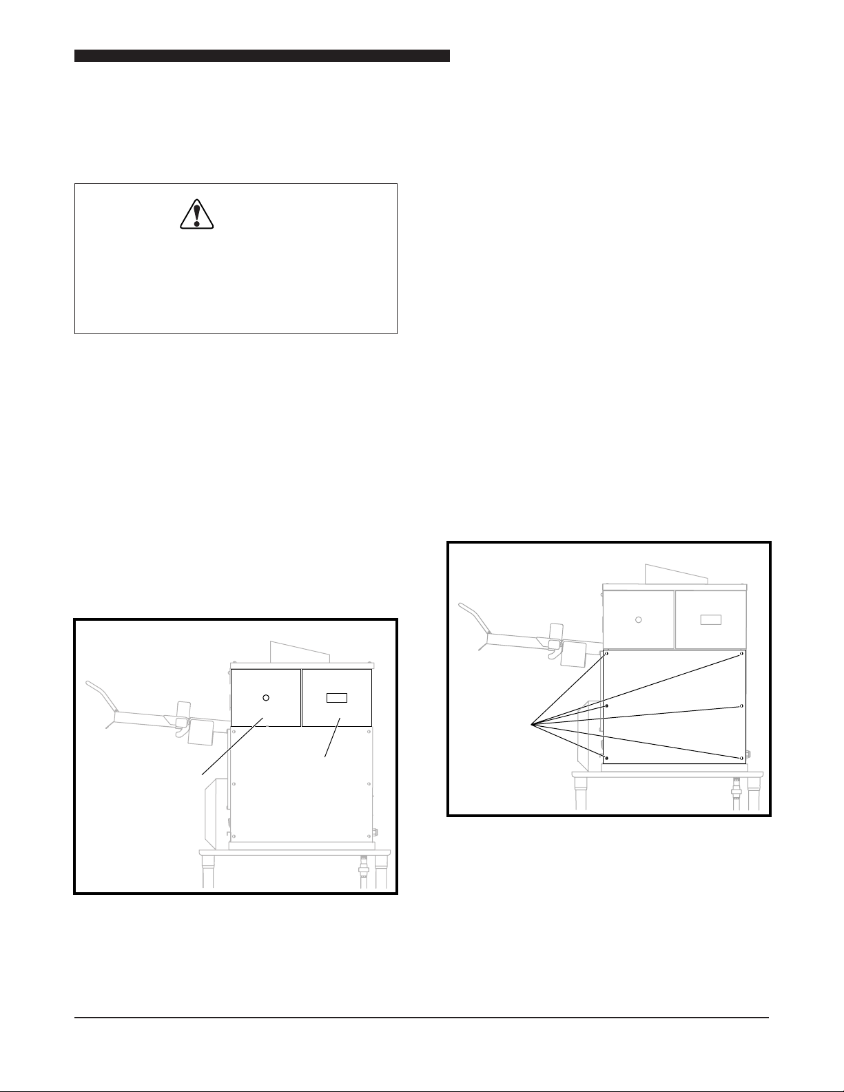
Fuse Access Panel
The Fuse Access Panel provides access to the
Upper Flame Sensors, Igniters and Blower Hose.
1. Remove Fuse Access Panel by lifting up and
removing from broiler.
1. First remove Fuse Access Panel. Refer to the
COVERS and PANELS section of the manual.
2. Remove Element Connection Access Panel
by lifting up and removing from broiler
3. Install Electrical Connection Access Panel by
lowering into the side grooves.
Electrical Access Panel
The Electrical Access Panel provides access to
the Transformers, Blower Motor, Conveyor Motor
Capacitor, and electrical connections to the Control
Board.
1. Remove the six screws securing the Electrical
Access Panel.
2. Remove the panel from the broiler.
3. Reverse procedure to install the Electrical
Access Panel.
2. Install Fuse Access Panel by lowering into the
side grooves.
Fuse
Access
Panel
Element
Connection
Access
Panel
Upper Access Panels
Element Connection Access Panel
The Element Connection Access Panel provides
access to the electrical connection for the Heating
Elements.
Screws
Electrical Access Panel
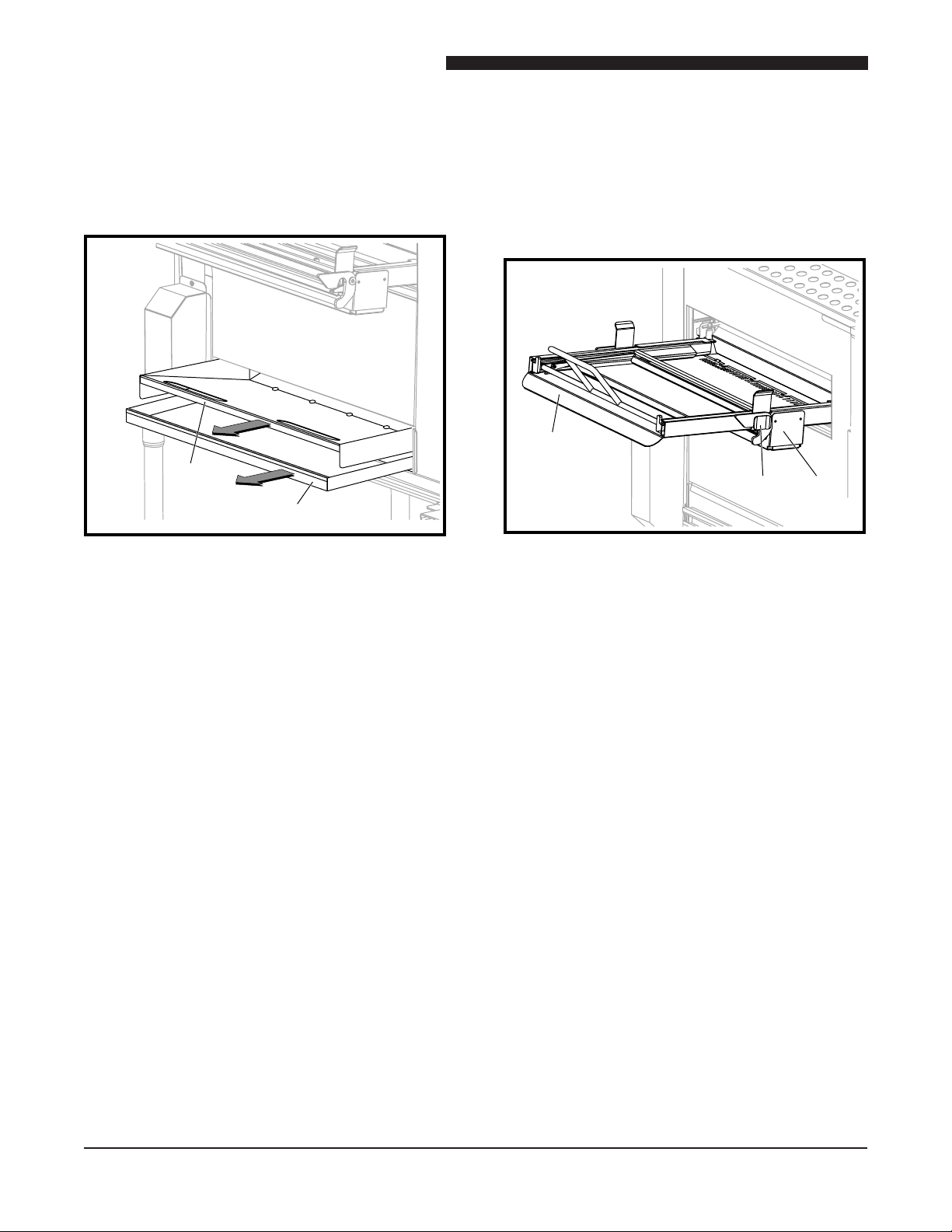
Product Pan Shelf
The Product Pan Shelf is located on the discharge
side of the broiler and holds the unused holding
pans.
1. Lift the pan shelf up and remove.
7

Service Manual for Flexible Batch Broiler Units
2. To install the pan shelf, slide the keyholes over
the two screws and slide pan shelf down.
Product
Pan
Shelf
Discharge
Hood
Product Pan Shelf and Discharge Hood
Discharge Hood
The Discharge Hood is located on the discharge
side of the broiler under the Product Pan Shelf.
1. Remove the Product Pan Shelf.
2. Remove the Discharge Hood by lifting out.
3. Install Discharge Hood by lowering into the
side grooves.
4. Reinstall the Product Pan Shelf.
Pin
Pin
Discharge
Chute Hook
Discharge Chute
Discharge Pan
The Discharge Pan is located on the discharge
side of the broiler below the Discharge Hood and
is used to support the Product Pan (not supplied).
1. Remove the Product Pan if present.
2. Slide Discharge Pan up and out of keyhole
slots.
3. Install Discharge Pan by lowering it into the
thumbscrews.
Discharge
Pan
Discharge Chute
The Discharge Chute is located under the
Discharge Hood and guides the patties from the
conveyor into the Discharge Pan.
1. Remove Product Pan Shelf.
2. Remove the Discharge Hood.
3. Remove Discharge Chute by lifting off of the
two side pins.
4. Reverse procedure to install Discharge Chute,
being sure to rest the hooks onto the pins on
both sides.
8
Discharge Pan
Discharge Grease Pan
The Discharge Grease Pan is located below the
Discharge Pan and catches any grease drippings.

1. Tilt Discharge Grease Pan up to unhook and
pull forward to remove.
2. When installing the Discharge Grease Pan,
be sure to tilt up and push all the way back.
NOTE: Correct positioning will not allow pan
removal without upward tilt.
1
2
Discharge
Grease
Pan
Service Manual for Flexible Batch Broiler Units
Discharge
Discharge
Side
Side
Access
Access
Panel
Panel
Discharge Access Panel
Main Grease Pan
The Main Grease Pan is located on the front of
the broiler under the Grease V-Pan.
Discharge Grease Pan
Discharge Access Panel
1. Remove the PHU Pan Shelf.
2. Remove Discharge Hood.
3. Remove Discharge Chute.
4. Remove Discharge Pan.
5. Remove Discharge Grease Pan.
6. Remove Discharge Access Panel by lifting it
up and out.
7. Reverse procedure to install Discharge Access
Panel.
Remove the Main Grease Pan by sliding straight
out of broiler.
9
Service Manual for Flexible Batch Broiler Units
Grease V-Pan
The Grease V-Pan is located on the front of the
broiler under the Loader Tray.
Remove pan by sliding straight out from broiler.
Grease
V-Pan
Main
Grease Pan
Grease V-Pan and Main Grease Pan
2. Remove Loader Tray from the Loader Brackets
by pulling forward and disengaging ears on
Loader Tray from keepers on the Loader
Brackets.
3. Install Loader Tray by sliding it into bracket
and engaging ears with keepers.
Loader
Carriage
Ear
Loader
Bracket
Loader Tray
Loader Tray
The Loader Tray is located on the front of the
broiler and slides into the channels on the Loader
Brackets.
1. Remove Loader by sliding it out of the Loader
Tray.
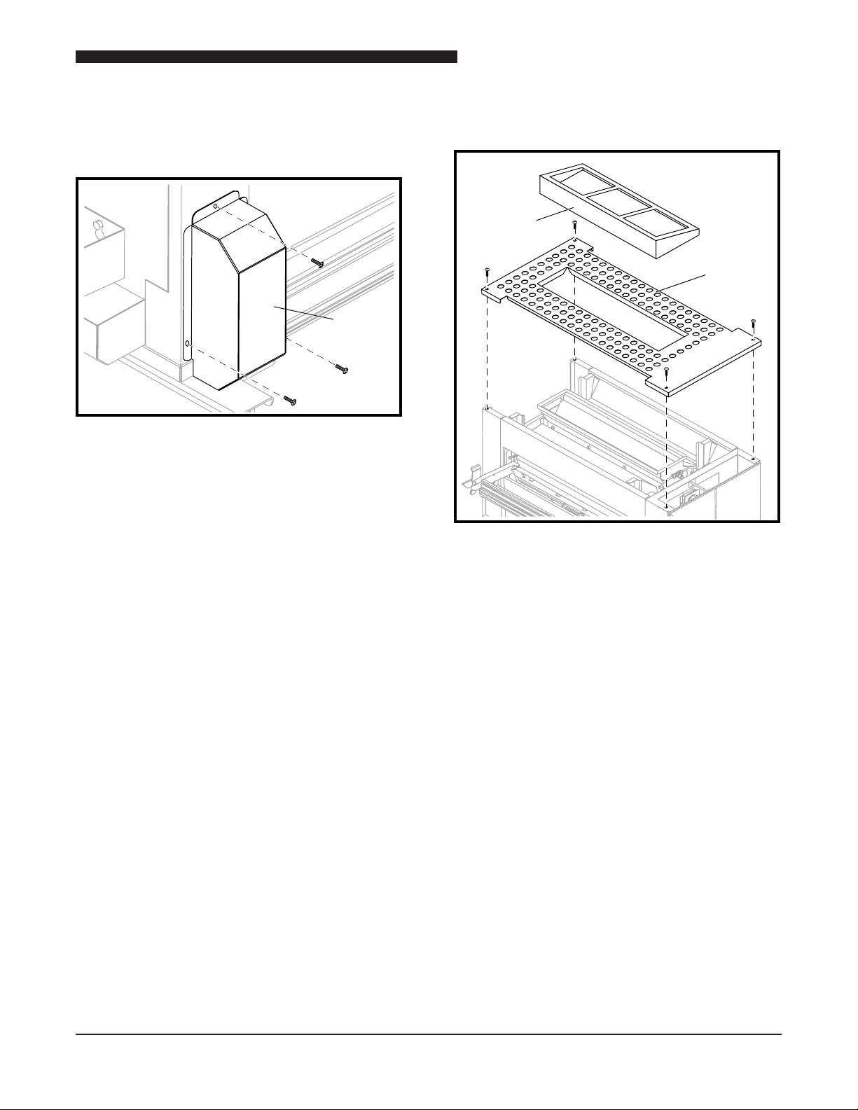
Conveyor Drive Motor Cover
The Conveyor Drive Motor Cover, located on the
lower front of the broiler on the discharge side,
covers the Drive Chain Motor.
1. Remove the Main Grease Pan and the Grease
V-Pan.
10
Service Manual for Flexible Batch Broiler Units
Conveyor
Drive
Motor
Cover
Top
Service
Panel
Catalyst
Guard
2. Remove the three screws securing the cover
to the broiler.
3. Lift Conveyor Drive Motor Cover off the broiler.
Conveyor Drive Motor Cover
Top Service Panel
3. Reverse procedure to install the perforated
Top Service Panel.
The perforated Top Service Panel provides access
to the two Infrared Burners
1. Remove the four screws securing the
perforated Top Service Panel.
2. Remove the perforated Top Service Panel
from the broiler.
Top Service Panel
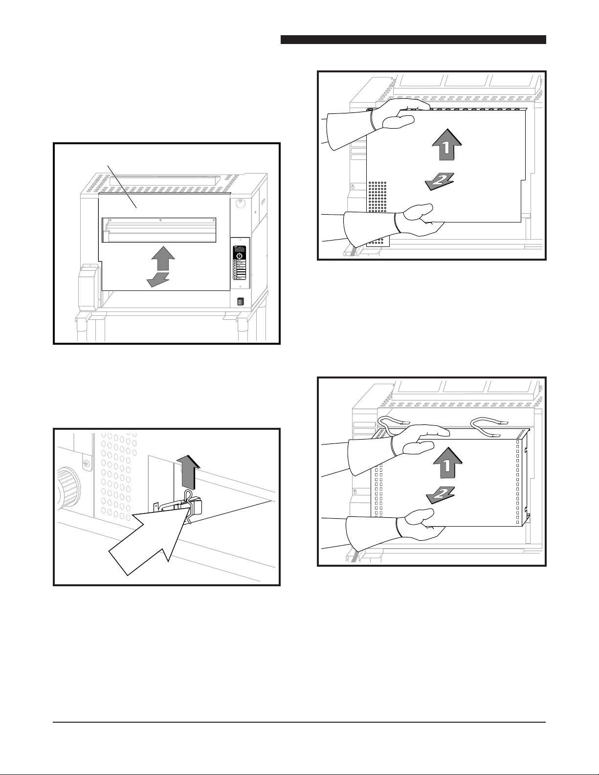
Removing the Front Panel
1. Slide the Loader out of the Loader Tray.
2. Unlatch the Loader Tray and slide it out of the
Loader Tray Mounting Brackets.
3. Pull the Main Grease Pan out of the front of
the broiler.
11
Service Manual for Flexible Batch Broiler Units
4. Pull the Grease V-Pan out of the front of the
broiler.
5. Lift Front Panel up and away from broiler.
6. Reverse these steps to reinstall these parts.
Front Access Panel
Rear Access Panel
Removing the Element Cover Panel
Front Panel
Removing the Rear Panel
1. Remove Cotter pin and unfasten latch.
Rear Panel Cotter Pin & Latch
2. Lift Rear Panel up and away from broiler.
3. Reverse to reinstall the Rear Panel.
1. Remove the Rear Panel
2. Lift the Element Cover Panel up and away
and remove from the broiler.
Element Cover Panel
3. The Panel is connected to the broiler with
safety cables. Swing the panel up and place
it on top of the broiler.
4. Reverse to reinstall the Element Cover Panel.
12
 Loading...