

Duke DSO 500 Service Manual
SPEED OVEN
MODEL
DSO 500
Service Manual
Please read this manual completely before attempting to
install, operate or service this equipment
This manual is Copyright ©2011 Duke Manufacturing Company. All rights reserved.
Reproduction without written permission is prohibited. Duke is a registered
trademark of the Duke Manufacturing Company.
Duke Manufacturing Company
2305 N. Broadway
St. Louis, MO 63102
Phone: 314-231-1130
Toll Free: 1-800-735-3853
Fax: 314-231-5074
www.dukemfg.com
P/N 168465B

Service Manual for Speed Oven Model DSO 500
2

SAFETY PRECAUTIONS
SAFETY PRECAUTIONS
PRECAUTIONS TO BE OBSERVED BEFORE AND DURING SERVICING TO AVOID POSSIBLE
EXPOSURE TO EXCESSIVE MICROWAVE ENERGY
(a) Do not operate or allow the oven to be operated with the door open.
(b) Make the following safety checks on all ovens to be serviced before activating the magnetron
or other microwave source, and make repairs as necessary.
(1) interlock operation
(2) proper door closing
(3) seal and sealing surfaces (arcing, wear, and other damage)
(4) damage to or loosening of hinges and latches
(5) evidence of dropping or abuse
(c) Before turning on microwave power for any service test or inspection within the microwave
generating compartments, check the magnetron, wave guide or transmission line, and cavity
for proper alignment, integrity, and connections.
(d) Any defective or misadjusted components in the interlock monitor, door seal, and microwave
generation and transmission systems shall be repaired, replaced, or adjusted by procedures
described in this manual before the oven is released to the owner.
(e) A microwave leakage check to verify compliance with the Federal Performance Standard should
be performed on each oven prior to release to the owner.
CAUTION: When servicing the unit, be sure no electrical wires contact a sharp edge.
Check all wiring for possible cuts and/or abrasions, which can occur during servicing.
3

Service Manual for Speed Oven Model DSO 500
TABLE OF CONTENTS
SAFETY PRECAUTIONS ....................................................................................................................3
INTRODUCTION .................................................................................................................................6
MAIN FEATURES ..........................................................................................................................7
INSTALLATION ...................................................................................................................................8
UNPACKING OVEN ......................................................................................................................8
RADIO INTERFERENCE ..............................................................................................................8
OVEN PLACEMENT......................................................................................................................8
ELECTRICAL INFORMATION .......................................................................................................8
EARTHING INSTRUCTIONS ........................................................................................................9
EXTERNAL EQUIPOTENTIAL ......................................................................................................9
SPECIFICATIONS .............................................................................................................................10
INPUT POWER ...........................................................................................................................10
OUTPUT POWER .......................................................................................................................10
DIMENSIONS ..............................................................................................................................10
WEIGHT ......................................................................................................................................10
RECOMMENDED CLEARANCES ..............................................................................................10
INTERNAL COOKING CAVITY DIMENSIONS............................................................................10
PREVENTIVE MAINTENANCE .........................................................................................................11
CLEANING ..................................................................................................................................11
SERVICING PROCEDURES ............................................................................................................12
GENERAL ....................................................................................................................................12
COMPONENT OVERVIEW ...............................................................................................................13
STIRRER MOTOR AND GEARBOX ...........................................................................................13
HIGH VOLTAGE TRANSFORMERS ...........................................................................................15
HIGH VOLTAGE RECTIFIERS ....................................................................................................17
HIGH VOLTAGE CAPACITORS ..................................................................................................19
MAGNETRONS ...........................................................................................................................21
MAGNETRON THERMAL SWITCHES .......................................................................................23
SOLID STATE RELAYS ...............................................................................................................25
MECHANICAL RELAYS AND INTERLOCK SWITCHES ............................................................27
HEATERS AND THERMAL CUTOUTS .......................................................................................29
LINE FUSES ................................................................................................................................31
JET PLATES ................................................................................................................................33
CABINET COOLING FANS .........................................................................................................35
4

TABLE OF CONTENTS
MAGNETRON COOLING FANS .................................................................................................37
CABINET THERMAL SWITCH ....................................................................................................39
KEYPAD/CONTROL BOARD ......................................................................................................41
INVERTERS ................................................................................................................................43
SYSTEM TESTING ...........................................................................................................................45
POWER OUTPUT MEASUREMENT ..........................................................................................45
MICROWAVE LEAKAGE TEST ...................................................................................................45
COMPONENT TESTING ...................................................................................................................47
POWER TRANSFORMER TEST ................................................................................................47
DISCHARGING THE HIGH VOLTAGE SYSTEM ON THE DUKE SPEED OVEN. .....................48
HIGH VOLTAGE CAPACITOR TEST ..........................................................................................49
HIGH VOLTAGE RECTIFIER TEST ............................................................................................50
MECHANICAL RELAYS AND INTERLOCK SWITCHES ............................................................51
REPAIR PROCEDURES ...................................................................................................................53
RELAY AND SWITCH REPLACEMENT ......................................................................................53
LINE FUSE REPLACEMENT ......................................................................................................54
INVERTER REPLACEMENT .......................................................................................................55
BLOWER MOTOR REPLACEMENT ...........................................................................................56
ELECTRICAL PANEL REPLACEMENT ......................................................................................58
MAGNETRON REPLACEMENT .................................................................................................59
STIRRER MOTOR REPLACEMENT ...........................................................................................60
HEATER ELEMENT REPLACEMENT ........................................................................................61
CABINET THERMAL SWITCH REPLACEMENT ........................................................................62
HIGH VOLTAGE TRANSFORMER REPLACEMENT..................................................................63
FRONT THERMAL COOLING FAN REPLACEMENT .................................................................64
INTAKE AND EXHAUST FANS REPLACEMENT .......................................................................65
ADJUSTMENTS ..........................................................................................................................66
TROUBLESHOOTING ......................................................................................................................67
SCHEMATIC DIAGRAM ....................................................................................................................71
SPARE PARTS LIST .........................................................................................................................72
APPENDIX A INVERTER PROGRAMMING .....................................................................................73
PROGRAMMING PROCEDURE .................................................................................................73
INVERTER SETTINGS................................................................................................................74
5

Service Manual for Speed Oven Model DSO 500
INTRODUCTION
7
512 10
1012 63 4
4
8 911
Figure 1
6

EQUIPMENT OVERVIEW
MAIN FEATURES
The main features of the Model DSO 500 Speed
Oven are identied in Figure 1 and described
below.
1. ON/OFF SWITCH
Turning ON the power switch will operate the
blower fans, stirrer motor and cooling system. It
will also activate the control panel and heat up
the oven to the temperature setting, which will
display “Oven Ready.
NOTE: When the Power Switch is turned “OFF”,
the rear mounted Cooling Fans will be
running until the unit has cooled down or
the power cord removed.
2. CONTROL PANEL
This is the electronic control board that is
programmable for different menus, temperature
setting, variable fan speed, Microwave Power
Connection only, Microwave and Convection
Combination, etc. This also has some service
diagnostics.
3. DRAIN PAN
This serves as the collector of any liquid from the
Oven cavity during cooking or cleaning.
4. OVEN CAVITY
The oven cavity is constructed from stainless
steel and must be kept clean. (See CARE and
CLEANING instructions in the OPERATOR’S
MANUAL). The top cavity has a thin jet plate and
the bottom cavity has the wire rack and bottom
jet plate. A drain plug is also provided for ease
of cleaning.
5. CONVECTION FAN
The unit has two blower systems (Top and
Bottom) for distributing the patented impingement
air system. Both blower systems can be operated independently over the entire speed range
for more precise control of cooking, browning,
etc. The perforated rear panel and the bottom
jet plates must be kept clean and free of debris.
(See CARE and CLEANING instructions in the
OPERATOR’S MANUAL).
6. DOOR AND HEAT SHIELD
The door is pulled downwards and towards you
to open. The door is designed with interlocks for
microwave safety. The door should NOT be used
to support heavy dishes. It must be kept clean.
The door includes a heat shield attached to the
front.(See CARE and CLEANING instructions in
the OPERATOR’S MANUAL).
7. DOOR SEAL
These ensure a seal around the door cavity. They
should be kept clean and checked regularly for
signs of damage.
8. REMOVABLE BOTTOM JET PLATE
The bottom jet plate directs the air from the
bottom of the oven to the underside of the
product.
9. DRAIN OUTLET AND PLUG
Remove drain plug when cleaning. (See CARE
and CLEANING instructions in the OPERATOR’S
MANUAL). Make sure it is replaced into position
before replacing bottom jet plate.
10. AIR OUTLETS
These air outlets and louvers on the left side,
right side and rear panels are part of the cooling
system of the electrical components. They must
be kept free from obstruction. It will not allow
microwave energy to escape into the environment. See clearance allowances specied in the
INSTALLATION Section of this manual.
11. EXHAUST VENT
The exhaust vent is at the rear of the oven. This
enables steam to escape and prevents build up of
condensation. It will not allow microwave energy
to escape into the environment.
12. COOLING FANS
Cooling Fans above the power cord are mounted to bring in cool air from the room into the
machinery compartment. The single fan below
the exhaust vent is directed to blow out the air
from the machinery compartment.
7
Service Manual for Speed Oven Model DSO 500
INSTALLATION
UNPACKING OVEN
• Inspect oven for damage such as dents
in door or inside oven cavity.
• Report any dents or breakage to source
of purchase immediately. Do not attempt
to use oven if damaged.
• Remove all materials from oven interior.
• If oven has been stored in extremely cold
area, wait a few hours before connecting
power.
RADIO INTERFERENCE
Microwave operation may cause interference
to radio, television, or similar oven. Reduce or
eliminate interference by doing the following:
• Clean door and sealing surfaces of oven
according to instructions in Care and
Cleaning instruction in the OPERATORS
MANUAL
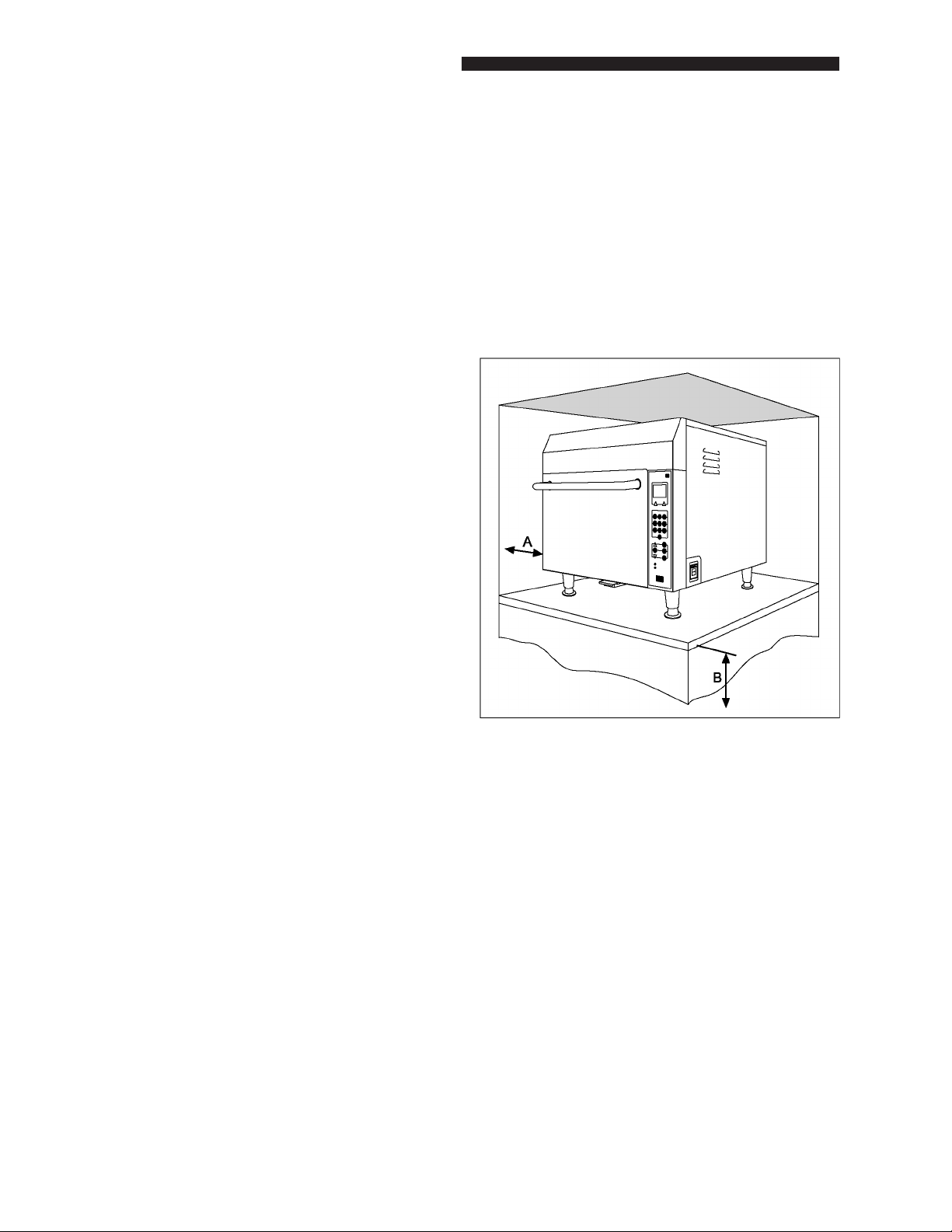
A. Allow at least 3” (7.62 cm) of clearance
around the sides of oven. Proper airow
around the oven cools electrical components. With restricted airow, the oven
may not operate properly and the life of
electrical parts is reduced.
B. Install oven so oven bottom is at least 3
feet (91.5 cm) above oor.
• Place radio, television, etc. as far as possible from oven
• Use a properly installed antenna on radio,
television, etc. to obtain stronger signal
reception
OVEN PLACEMENT
• Do not install oven next to or above source
of heat, such as pizza oven or deep fat
fryer. This could cause microwave oven
to operate improperly and could shorten
life of electrical parts
• Install oven on level countertop surface
• If provided, place warning label in a
conspicuous place close to microwave
oven
• Outlet should be located so that plug is
accessible when oven is in place
• Provide clearance as shown in Figure 2
and described in the following paragraphs
“A” and “B”
Figure 2. Oven Clearance Dimensions
ELECTRICAL INFORMATION
The switching operation of this microwave oven
can cause voltage uctuations on the supply
line. The operation of this oven under unfavorable voltage supply conditions can have adverse
effects. This device is intended for the connection to a power supply system with maximum
permissible system impedance Zmax of 1.1 Ohm
at the interface point of the user’s supply. The
user has to ensure that this device is connected
only to a power supply system, which fullls the
requirement above, If necessary, the user can ask
the public power supply company for the system
impedance at the interface point. The circuit
breakers used in this oven are Type C.
8
EQUIPMENT OVERVIEW
WARNING
TO AVOID RISK OF ELECTRICAL SHOCK OR
DEATH, THIS OVEN MUST BE GROUNDED
AND PLUG MUST NOT BE ALTERED.
WARNING
IMPROPER USE OF THE GROUNDING CAN
RESULT IN RISK OF ELECTRICAL SHOCK.”
CONSULT A QUALIFIED ELECTRICIAN
OR SERVICEMAN. IF THE GROUNDING
INSTRUCTIONS ARE NOT COMPLETELY
UNDERSTOOD, OR IF DOUBT EXISTS AS
TO WHETHER THE APPLIANCE IS PROPERLY GROUNDED, AND “DO NOT USE AN
EXTENSION CORD. IF THE POWER SUPPLY
CORD IS TOO SHORT, HAVE A QUALIFIED
ELECTRICIAN OR SERVICEMAN INSTALL
AN OUTLET NEAR THE APPLIANCE.
If the product power cord is too short, have a
qualied electrician install a three-slot receptacle.
This oven should be plugged into a separate
circuit with the electrical rating as provided in
product specifications (available on Duke’s
Wavelink website).
EXTERNAL EQUIPOTENTIAL
Earthing Terminal (export only)
Equipment has secondary earthing terminal.
Terminal provides external earthing connection used in addition to earthing prong on plug.
Located on outside of oven back, terminal is
marked with this symbol.
WARNING
EARTHING INSTRUCTIONS
WARNING
OVEN MUST BE GROUNDED.
Grounding reduces risk of electric shock by
providing an escape wire for the electric current if
an electrical short occurs. This oven is equipped
with a cord having a grounding wire with a
grounding plug. The plug must be plugged into
an outlet that is properly installed and grounded.
Consult a qualied electrician or service provider if grounding instructions are not completely
understood, or if doubt exists as to whether the
oven is properly grounded.
CAUTION: Do not use an extension cord.
DO NOT R EMOVE EARTHING PRONG
WHEN INSTALLING EARTHED APPLIANCE
IN A LOCATION THAT DOES NOT HAVE
THREE WIRE EARTHING RECEPTACLE,
UNDER NO C ONDITION IS EARTHING
PRONG TO BE CUT OFF OR REMOVED. IT IS
THE PERSONAL RESPONSIBILITY OF THE
EQUIPMENT OWNER TO CONTACT A QUALIFIED ELECTRICIAN AND HAVE PROPERLY
EARTHED THREE PRONG WALL RECEPTACLE INSTALLED IN ACCORDANCE WITH
APPROPRIATE ELECTRICAL CODES.
Wire Color Code
The standard accepted color coding for earthing
wires is Green or green with a yellow strip.
WARNING
EARTHING LEADS ARE NOT INTENDED TO
CARRY CURRENT IN NORMAL OPERATION.
The service technician must replace all earths
prior to completion of the service call. Under no
condition should earth wire be left off causing
a potential hazard to service technicians and
consumer.
9

Service Manual for Speed Oven Model DSO 500
SPECIFICATIONS
Table 2 lists the specications for the Model DSO 500 Speed Oven.
Table 2. Specications
MODEL NO. DSO 500
INPUT POWER
Operating Voltage 208 – 240 VAC, 60 Hz
Current 29 Amps
Phase Single
Circuit Breaker 30A, Type C or D
OUTPUT POWER
Microwave 1600 Watts
Heaters 5400 Watts
DIMENSIONS
Height 26 in. (with 4 in. legs)
Width 25 7/8 in.
Depth 31 in. (incl. door handle)
WEIGHT
Unpacked Approximately 250 lbs.
Packed 360 lbs.
RECOMMENDED CLEARANCES
Height None required
Width 3 inches on each side
Depth None required
INTERNAL COOKING CAVITY DIMENSIONS
Height 8 in.
Width 16 in.
Depth 14-1/2 in.
10

PREVENTIVE MAINTENANCE
EQUIPMENT OVERVIEW
CLEANING
Stainless Steel Care and Cleaning
To prevent discoloration or rust on stainless steel
several important steps need to be taken. First,
we need to understand the properties of stainless steel. Stainless steel contains 70-80% iron
which will rust. It also contains 12-20% chromium
which forms an invisible passive lm over the
steels surface which acts as a shield against
corrosion. As long as the protective layer is
intact, the metal will not corrode. If the lm is
broken or contaminated, outside elements can
begin to breakdown the steel and begin to form
rust or discoloration.
Proper cleaning of stainless steel requires soft
cloths or plastic scouring pads.
CAUTION: Never use steel pads, wire brushes
or scrapers.
Early signs of stainless steel breakdown can
consist of small pits and cracks. If this has
begun, clean thoroughly and start to apply stainless steel cleaners in attempt to restore the
passivity of the steel.
WARNING
THE POWER MUST BE TURNED OFF AND
POWER CORD DISCONNECTED WHENEVER PERFORMING MAINTENANCE OR
REPAIR FUNCTIONS.
Gasket Maintenance
Gaskets require regular cleaning. Gasket cleaning can be done with the use of warm soapy
water. Also, never use sharp tools or knives to
scrape or clean the gasket which could possibly
damager the gasket.
Cleaning solutions need to be alkaline based or
non-chloride cleaners. Any cleaner containing
chlorides will damage the protective lm of the
stainless steel. Chlorides are also commonly
found in hard water, salts and household and
industrial cleaners. If cleaners containing chlorides are used, be sure to rinse repeatedly and
dry thoroughly upon completion.
Routine cleaning of stainless steel can be done
with soap and water. Extreme stains or grease
should be cleaned with a non-abrasive cleaner
and plastic scrub pad. It is always good to rub
with the grain of the steel. There are also stainless steel cleaners available which can restore
and preserve the nish of the steels protective
layer.
11

Service Manual for Speed Oven Model DSO 500
SERVICING PROCEDURES
GENERAL
The service section of this manual includes a
section called component overview. Information
on each component is a separate page. This
overview is not intended to provide detailed
information. Its purpose is to provide a general
understanding of what the component does and
how it is tested and replaced. When a procedure
is to be performed, refer to the detailed REPAIR
PROCEDURES. The information in this overview
includes the following:
• A general description of the function of
the component in the oven operation
• Location and Access information
• Safety Issues
• Tools Required
• Operational Testing
• Test Procedure
• Replacement Procedure
NOTE: Remember this overview is only intended
to provide a brief discussion on each component. Details for testing, adjusting and
replacement are provided separately in
the TESTING and REPAIR section of this
manual and should be referred to when
performing any procedure.
In addition to the Overview section this chapter
includes the following:
• Power Output Measurement
• Microwave Leakage Test
• Component Detailed Testing
• Detai l ed Re p air an d Re p l acement
Procedures
• Adjustment Procedures
• Troubleshooting Procedures
Additional chapters provide the Schematic Diagram and the Spare Parts list.
12
COMPONENT OVERVIEW
COMPONENT OVERVIEW
STIRRER MOTOR AND GEARBOX
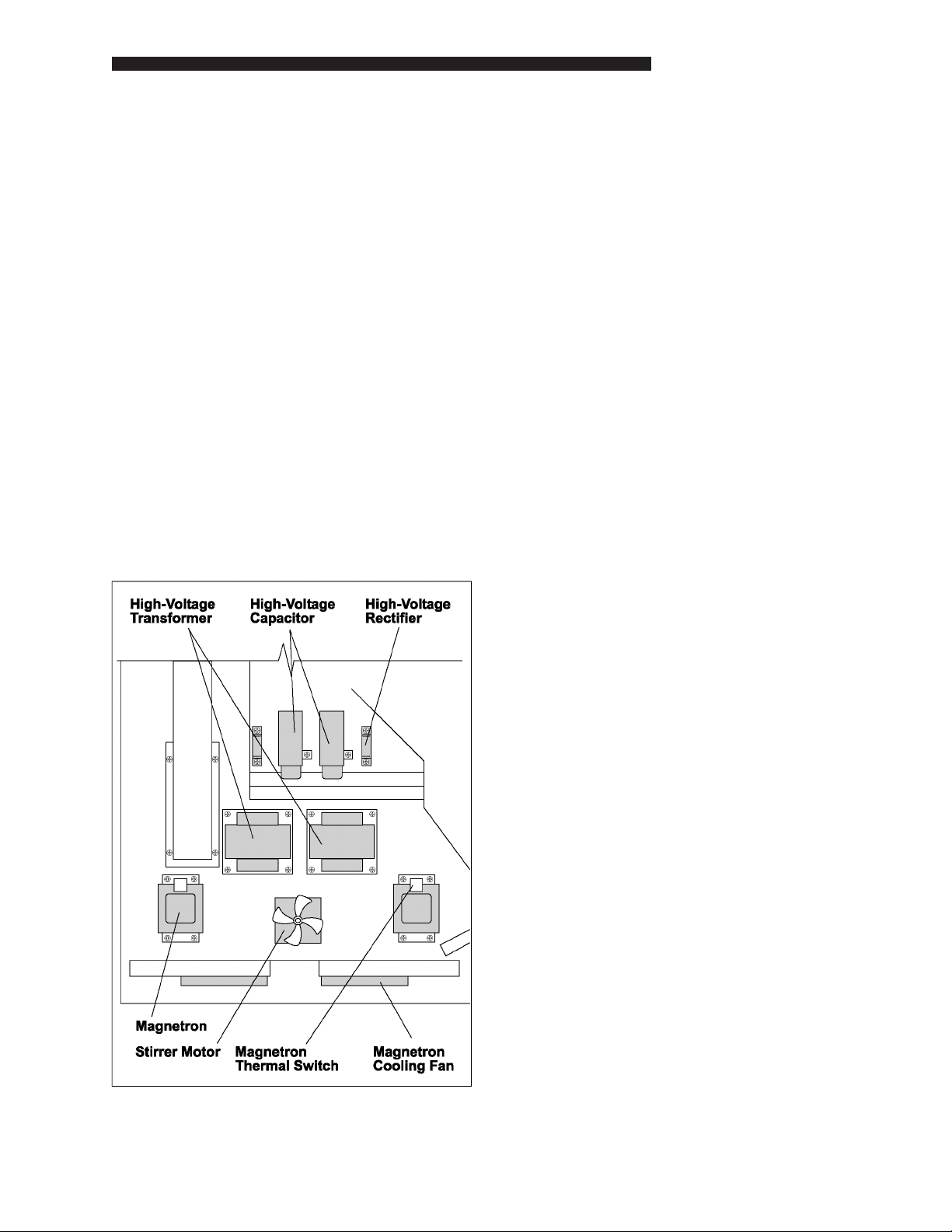
The stirrer motor and gearbox, Figure 3, is
located near the front of the oven upper chamber above the upper jetplate. The stirrer motor
rotates the stirrer blade at 20 rpm. The rotating
stirrer blade evenly distributes the microwave
eld and the upper hot airow into the cook
chamber to ensure uniformity. Should the stirrer
blade cease to rotate during cooking, severe nonuniformity of cooking will be observed. Localized
burning of the food may occur and in the case of
cooking frozen food, very cold uncooked areas
may be detected.
Location and access
The stirrer motor is centrally located above the
top of the cook chamber. The top and side panels
will need to be removed.
Surface Components
Safety issues
• Electrical supply of 208/240 VAC to stirrer
motor which becomes live when power
cord is live
• Proximity to High Voltage system (5
kVDC) which can remain live, even after
power down
• Upper end of motor shaft rotates rapidly
with small exposed cooling fan
Tools required
• Flat blade screwdriver to remove top and
side panels
• 11/32 inch nut driver to remove nuts se-
curing motor and gearbox to top of oven
• Voltmeter
• Flash light
Operational testing
The stirrer motor is powered from the 208/240
VAC mains supply and is not controlled from
the main on/off switch on the right hand side.
The door safety interlocks interrupt this supply
when the door is opened, so that the stirrer blade
is stationary whenever the door is opened. The
interlock function should be checked by opening and closing the cook door and observing the
rotation of the stirrer motor fan. The rotation of
the stirrer blade can be checked by removing
the upper jet plate or observing the position
of the stirrer blade through the air holes in the
upper jet plate with a ashlight.
Figure 3. High Voltage and Inside Top
13

Service Manual for Speed Oven Model DSO 500
Test procedure
Check 208/240 VAC is present on the motor
power connections, wires 47 and 49, as above.
If power is not present, check incoming line voltage, line fuses, mechanical relays K6, K8 and
primary and secondary door switches.
If power is present at all times, the door interlock
safety system has failed. Check the mechanical
relays K6, K8 and primary and secondary door
switches.
STIRRER MOTOR AND GEARBOX - NOTES
Replacement
After removing the side and top panels and
disconnecting the power cord, the stirrer motor
power leads can be disconnected. There are
four 11/32 inch nuts securing the stirrer motor
and gearbox. Upon retting, align the dnveshaft
of the gearbox with the head of the coupling to
the stirrer blade.
14
COMPONENT OVERVIEW
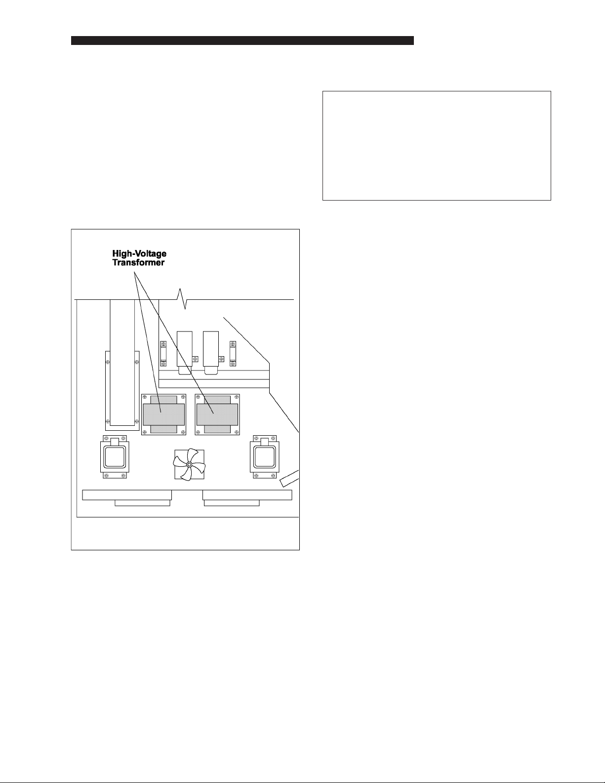
HIGH VOLTAGE TRANSFORMERS
The transformers, Figure 4, step up the input line
voltage to 2.5 kV. This voltage is rectied by the
high voltage diodes and the high voltage capacitors for operation of the magnetrons.
Location and Access
The transformers are centrally located above
the top of the cook chamber. The top and side
panels will need to be removed.
Safety Issues
WARNING
THE HIGH VOLTAGE CAPACITORS RETAINS
THE 2.5 kVDC CHARGE EVEN AFTER THE
OVEN IS DISCONNECTED. THIS CAPACITOR MUST BE DISCHARGED BEFORE
WORKING ON ANY COMPONENTS IN THE
HIGH VOLTAGE AREA.
• Electrical supply of 208/240 VAC to trans-
formers when POWER switch is in ON
position and oven doors are closed
Tools Required.
• Flat blade screwdriver to remove top and
side panels
• 3/8 inch nut driver to remove nuts secur-
ing transformers to top of oven
• Voltmeter
Figure 4. High Voltage Transformers
Operational Testing.
The transformers are powered from the 208/240
VAC mains supply through solid state relays K4
and K5 and mechanical relay K6 and K8. Relays K6 and K8 are controlled by the door safety
interlock requiring the oven door to be closed
to provide primary voltage to the transformers.
The door safety interlocks interrupt this supply
when the door is opened. Operation of relays K4
and K5 required the POWER switch to be in the
ON position to provide operating voltage to the
control board. The interlock function can be
checked by opening and closing the oven door
and observing the rotation of the blade on top of
the stirrer motor.
15

Service Manual for Speed Oven Model DSO 500
Test Procedure
WARNING
HIGH VOLTAGE CAPACITOR MUST BE
DISCHARGED BEFORE SERVICING. REFER TO DETAILED PROCEDURE IN THE
COMPONENT TESTING SECTION BEFORE
TESTING.
NOTE: Dangerous voltages can be present at
this component. Refer to detailed test
procedure for testing this component.
Check 208/240 VAC is present on the transformer primaries, wires 26 and 45 for mag #1
transformers and wires 27 and 48 for mag #2
transformer.
If power is not present, check incoming line voltage, line fuses, mechanical relays K6, K8 and
primary and secondary door switches.
Replacement
WARNING
THE HIGH VOLTAGE CAPACITOR RETAINS
THE 2.5 kVDC CHARGE EVEN AFTER THE
OVEN IS DISCONNECTED. THIS CAPACITOR MUST BE DISCHARGED BEFORE
WORKING ON ANY COMPONENTS IN THE
HIGH VOLTAGE AREA.
After removing the side and top panels and
disconnecting the power cord, the transformer
primary and secondary leads can be disconnected. There are four 3/8 inch nuts securing the
transformers.
If power is present at all times, the door interlock
safety system has failed. Check the mechanical
relays K6, K8 and primary and secondary door
switches and POWER ON/OFF switch.
HIGH VOLTAGE TRANSFORMERS - NOTES
16
COMPONENT OVERVIEW
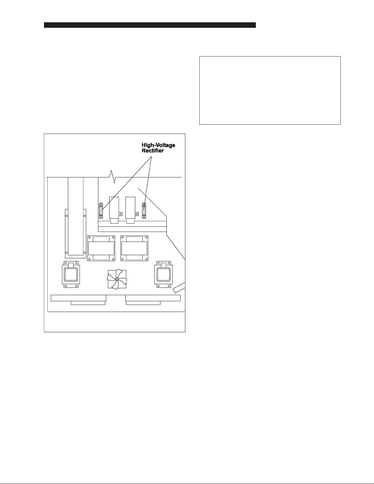
HIGH VOLTAGE RECTIFIERS
The high voltage diodes, Figure 5, rectify the
incoming 2.5 kV voltage and doubles it providing
5kVDC for magnetron operation.
Location and Access
The diodes are located above the top of the cook
chamber at the rear of the oven. The top and side
panels will need to be removed.
Safety Issues
WARNING
THE HIGH VOLTAGE CAPACITOR RETAINS
THE 2.5 kVDC CHARGE EVEN AFTER THE
OVEN IS DISCONNECTED. THIS CAPACITOR MUST BE DISCHARGED BEFORE
WORKING ON ANY COMPONENTS IN THE
HIGH VOLTAGE AREA.
• Electrical supply of 208/240 VAC to trans-
formers when POWER switch is in ON
position and oven doors are closed
Tools Required
• Flat blade screwdriver to remove top and
side panels
• Phillips #2 screwdriver to remove screws
securing diodes to top of oven
• Ohmmeter to check diodes
Figure 5. High Voltage Rectiers
Operational Testing
The transformers connected to the diodes are
powered from the 208/240 VAC mains supply through solid state relays K4 and K5 and
mechanical relay K6 and K8. Relays K6 and
K8 are controlled by the door safety interlock
requiring the oven door to be closed to provide
primary voltage to the transformers. The door
safety interlocks interrupt this supply when the
door is opened. Operation of relays K4 and K5
require the POWER switch to be in the ON position to provide operating voltage to the control
board. The interlock function can be checked by
opening and closing the oven door and observing the rotation of the blade on top of the stirrer
motor.
17

Service Manual for Speed Oven Model DSO 500
Test Procedure
WARNING
HIGH VOLTAGE CAPACITOR MUST BE
DISCHARGED BEFORE SERVICING. REFER TO DETAILED PROCEDURE IN THE
COMPONENT TESTING SECTION BEFORE
TESTING.
NOTE: Dangerous voltages can be present at
this component. Refer to detailed test
procedure for testing this component.
Disconnect the wires to the diodes. Use an ohmmeter to check diodes. Diodes should conduct
in one direction showing low resistance and not
conduct in the reverse direction, thus indicating
a very high resistance. High or low resistance in
both directions indicates a defective diode.
HIGH VOLTAGE RECTIFIERS - NOTES
Replacement
WARNING
HIGH VOLTAGE CAPACITOR MUST BE
DISCHARGED BEFORE SERVICING THE
TRANSFORMERS
After removing the side and top panels and
disconnecting the power cord, the diode leads
can be disconnected. There are two screws
securing each diode.
18
COMPONENT OVERVIEW
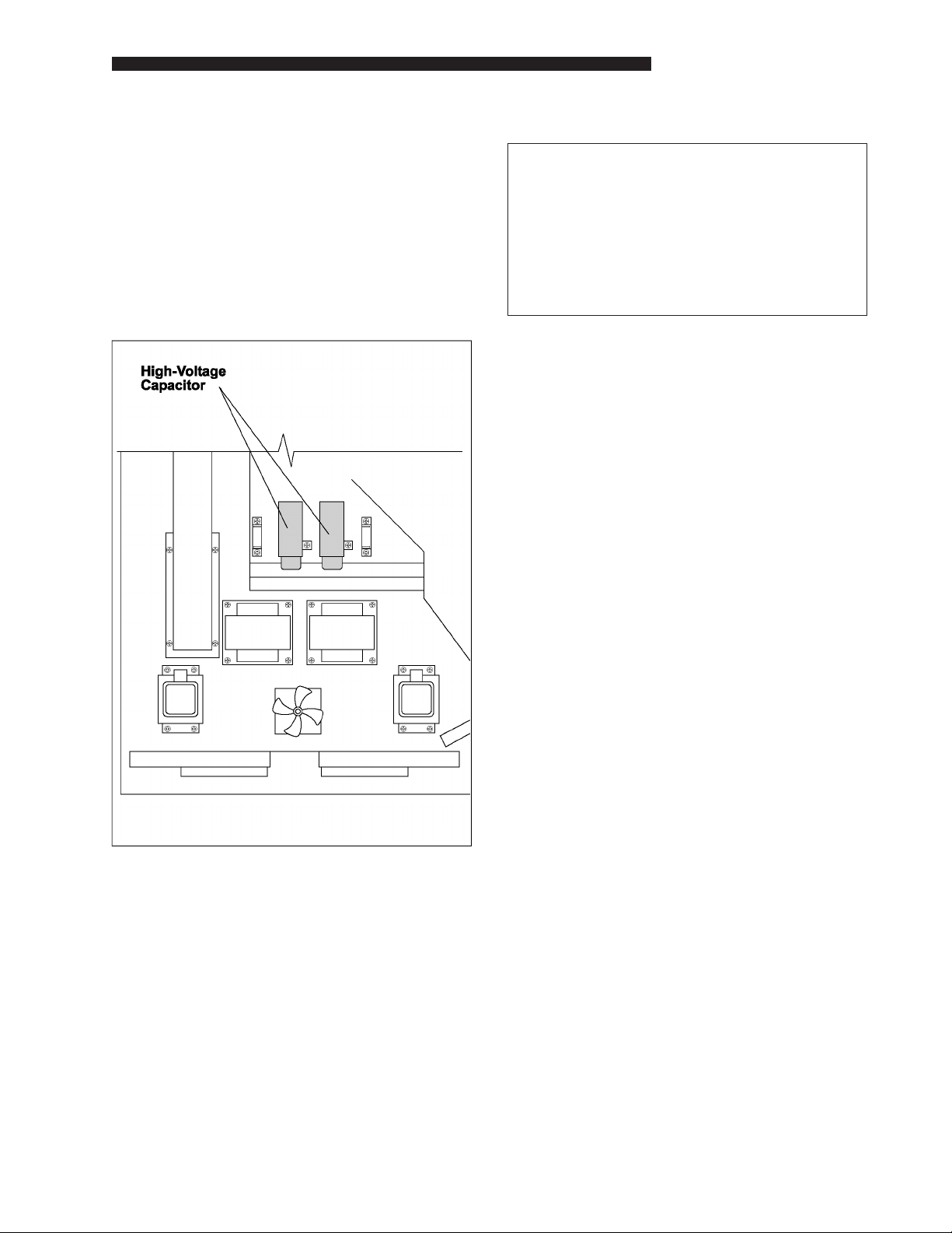
HIGH VOLTAGE CAPACITORS
The high voltage capacitors, Figure 6, store the
rectied high voltage (2.5 kVDC) for operation of
the magnetrons.
Location and Access.
The capacitors are located above the top of the
cook chamber at the rear of the oven. The top
and side panels will need to be removed.
Safety Issues
WARNING
THE HIGH VOLTAGE CAPACITOR RETAINS
THE 2.5 kVDC CHARGE EVEN AFTER THE
OVEN IS DISCONNECTED. THIS CAPACITOR MUST BE DISCHARGED BEFORE
WORKING ON ANY COMPONENTS IN THE
HIGH VOLTAGE AREA.
• Electrical supply of 208/240 VAC to trans-
formers when POWER switch is in ON
position and oven doors are closed
• Capacitors charge to the 2.5 kVDC level
when the high voltage circuit is properly
operating
Tools Required
• Flat blade screwdriver to remove top and
side panels
Figure 6. High Voltage Capacitors
• 5/16 inch nut driver to remove nuts secur-
ing diodes to top of oven
• Ohmmeter to check capacitors
Operational Testing
The capacitors charge whenever the transformer
is operating. The transformers connected to the
diodes for charging the capacitors are powered
from the 208/240 VAC mains supply through solid
state relays K4 and K5 and mechanical relay K6
and K8. Relays K6 and K8 are controlled by the
door safety interlock requiring the oven door to
be closed to provide primary voltage to the transformers. The door safety interlocks interrupt this
supply when the door is opened. Operation of
relays K4 and K5 require the POWER switch to
be in the ON position to provide operating voltage to the control board. The interlock function
can be checked by opening and closing the oven
door and observing the rotation of the fan on top
of the stirrer motor.
19

Service Manual for Speed Oven Model DSO 500
Test Procedure
WARNING
HIGH VOLTAGE CAPACITOR MUST BE
DISCHARGED BEFORE SERVICING. REFER TO DETAILED PROCEDURE IN THE
COMPONENT TESTING SECTION BEFORE
TESTING.
NOTE: Dangerous voltages can be present at
this component. Refer to detailed test
procedure for testing this component.
HIGH VOLTAGE CAPACITORS - NOTES
Replacement
WARNING
HIGH VOLTAGE CAPACITOR MUST BE
DISCHARGED BEFORE REPLACEMENT.
Capacitor must be discharged before removal.
After discharging, disconnect leads. There are
two nuts securing the capacitor bracket.
20

COMPONENT OVERVIEW
MAGNETRONS
The magnetron filament voltage of 4.5 VAC
is supplied from the high voltage transformer
lament winding. The operating voltage of 5000
VDC is provided by the rectied output from the
transformer high voltage winding.
Location and Access
The magnetrons, Figure 7, are located above the
top of the cook chamber at the left and right side
of the oven. The top and side panels will need
to be removed.
Safety Issues
WARNING
THE HIGH VOLTAGE CAPACITOR RETAINS
THE 2.5 kVDC CHARGE EVEN AFTER THE
OVEN IS DISCONNECTED. THIS CAPACITOR MUST BE DISCHARGED BEFORE
WORKING ON ANY COMPONENTS IN THE
HIGH VOLTAGE AREA.
• Electrical supply of 208/240 VAC to trans-
formers when POWER switch is in ON
position and oven doors are closed
• Capacitors charge to the 2.5 kVDC level
when the high voltage circuit is properly
operating
• The 4.5 VAC magnetron lament supply
is at 2500 V relative to the chassis
Tools required
Figure 7. Magnetrons
• Flat blade screwdriver to remove top and
side panels
• 3/8 inch nut driver to remove nuts secur-
ing the magnetrons to top of oven
Operational Testing.
The magnetrons receive lament and high voltage from the high voltage transformers. The
transformers connected to the diodes for charging the capacitors are powered from the 208/240
VAC mains supply through solid state relays K4
and K5 and mechanical relay K6 and K8. Relays K6 and K8 are controlled by the door safety
interlock requiring the oven door to be closed to
provide primary voltage to the transformers. The
door safety interlocks interrupt this supply when
the door is opened. Operation of relays K4 and
K5 require the POWER switch to be in the ON
position to provide operating voltage to the control board. The interlock function can be checked
by opening and closing the oven door and
observing the rotation of the blade on top of the
stirrer motor.
21

Service Manual for Speed Oven Model DSO 500
Test Procedure
WARNING
HIGH VOLTAGE CAPACITOR MUST BE
DISCHARGED BEFORE SERVICING. REFER TO DETAILED PROCEDURE IN THE
COMPONENT TESTING SECTION BEFORE
TESTING.
NOTE: Dangerous voltages can be present at
this component. Refer to detailed test
procedure for testing this component.
MAGNETRONS - NOTES
Replacement
WARNING
HIGH VOLTAGE CAPACITOR MUST BE
DISC H ARGED BEFORE M AGNETRON
REPLACEMENT.
Remove cooling duct. (Right side magnetron
only). Label and disconnect wires from transformer to magnetron lament. Disconnect wires
to thermostat. Remove nuts attaching magnetron
to top surface. When installing the new magnetron, be sure metal mesh gasket is properly
positioned around the magnetron dipole antenna
and that thermostat is installed on magnetron.
Secure magnetron to top surface with nuts.
Reconnect wires to lament and thermostat.
22

COMPONENT OVERVIEW
MAGNETRON THERMAL
SWITCHES
The magnetron thermal switches, Figure 8, are
used to monitor the magnetron temperature and
open the high voltage supply when the temperature exceeds 150°C.
Location and Access
The magnetrons thermostats are located on the
side of each magnetron. The top and side panels
will need to be removed.
Safety Issues
WARNING
THE HIGH VOLTAGE CAPACITOR RETAINS
THE 2.5 kVDC CHARGE EVEN AFTER THE
OVEN IS DISCONNECTED. THIS CAPACITOR MUST BE DISCHARGED BEFORE
WORKING ON ANY COMPONENTS IN THE
HIGH VOLTAGE AREA.
• Electrical supply of 208/240 VAC to trans-
formers when POWER switch is in ON
position and oven doors are closed
• Capacitors charge to the 2.5 kVDC level
when the high voltage circuit is properly
operating
Tools required
• Flat blade screwdriver to remove top and
side panels
Figure 8. Magnetron Thermal Switches
• 3/8 inch nut driver to remove nuts secur-
ing the magnetrons to top of oven
Operational Testing
The thermostats are connected in the high voltage transformer primary circuit and are normally
closed connecting primary voltage on wires 26
and 27 to the high voltage transformer. If magnetron is not operating check continuity across
thermostat terminals.
23

Service Manual for Speed Oven Model DSO 500
Test Procedure
WARNING
HIGH VOLTAGE CAPACITOR MUST BE
DISCHARGED BEFORE SERVICING. REFER TO DETAILED PROCEDURE IN THE
COMPONENT TESTING SECTION BEFORE
TESTING.
NOTE: Dangerous voltages can be present at
this component. Refer to detailed test
procedure for testing this component.
NOTE: Disconnect wires to thermostat and check
continuity across thermostat terminals.
Continuity should be indicated when
thermostat is at normal ambient temperature.
MAGNETRON THERMAL SWITCHES - NOTES
Replacement
WARNING
HIGH VOLTAGE CAPACITOR MUST BE
DISC H ARGED BEFORE M AGNETRON
THERMOSTAT REPLACEMENT.
Label and disconnect wires to thermostat. Remove screw securing thermostat to magnetron
and remove thermostat. When installing a new
thermostat, secure with screw. Connect wires to
thermostat.
24
 Loading...