

Duke DG2 Service Manual
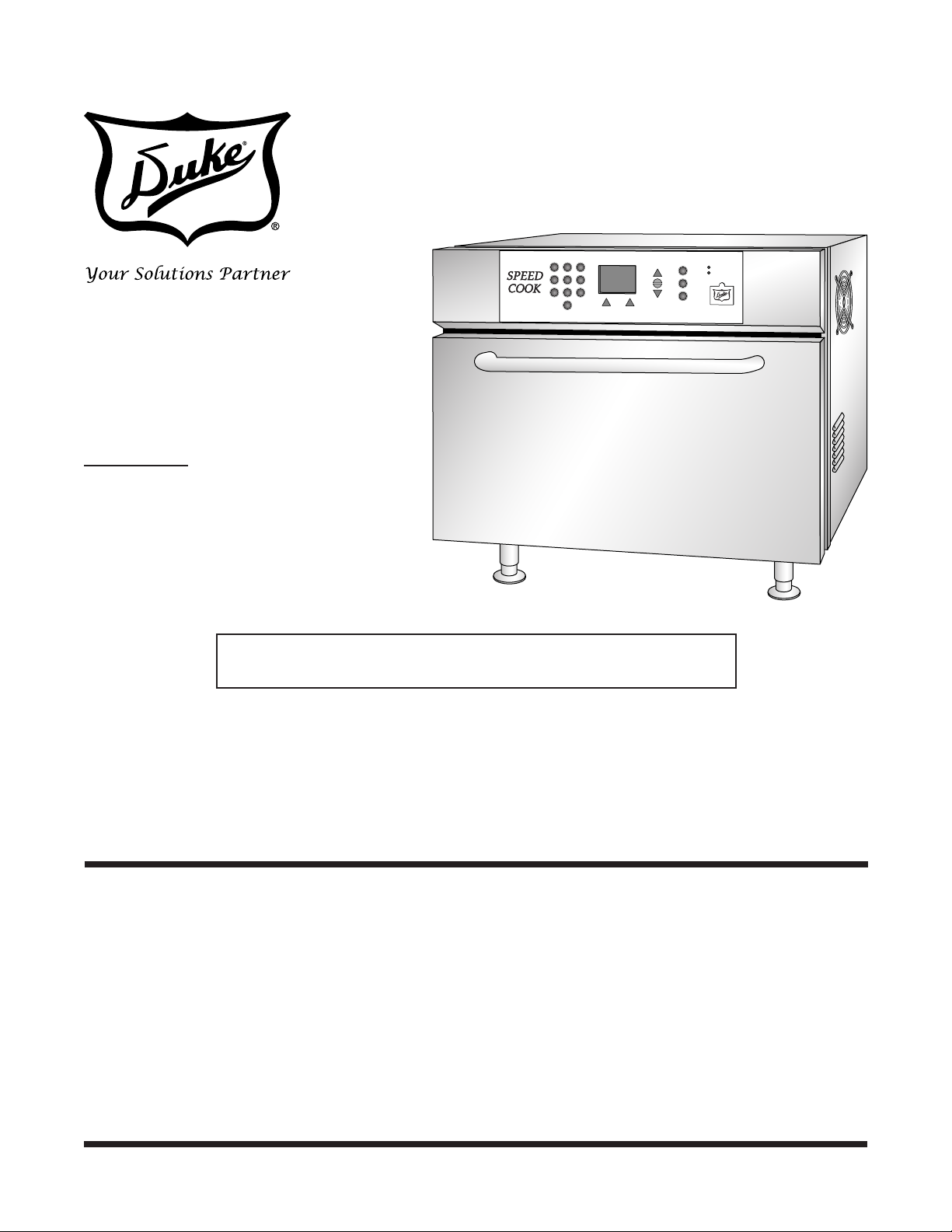
SPEED OVEN
MODEL
DG2
Service Manual
Please read this manual completely before attempting
to install, operate or service this equipment
This document is prepared for trained Duke service technicians. It is not to be used by anyone not
properly qualied to perform these procedures.
This Service Manual is not all encompassing. If you have not been trained on servicing this product,
be sure to read the manual completely before attempting servicing. Be sure all necessary tools, test
equipment, and skills are available. Those procedures for which you do not have the proper skills
and test equipment must be performed only by a qualied Duke trained service technician.
This manual is Copyright © 2010 Duke Manufacturing Co. All rights reserved.
Reproduction without written permission is prohibited. Duke is a registered
trademark of the Duke Manufacturing Co.
Duke Manufacturing Co.
2305 N. Broadway
St. Louis, MO 63102
Phone: 314-231-1130
Toll Free: 1-800-735-3853
Fax: 314-231-5074
www.dukemfg.com
P/N 168757A
Service Manual for DG2 Speed Oven
IMPORTANT WARNING AND SAFETY INFORMATION
THIS MANUAL HAS BEEN PREPARED FOR PERSONNEL QUALIFIED TO INSTALL
ELECTRICAL EQUIPMENT, WHO SHOULD PERFORM THE INITIAL FIELD STARTUP AND
ADJUSTMENTS OF THE EQUIPMENT COVERED BY THIS MANUAL.
READ THIS MANUAL THOROUGHLY BEFORE OPERATING, INSTALLING OR
PERFORMING MAINTENANCE ON THE EQUIPMENT.
Failure to follow all the instructions
in this manual can cause property damage, injury
or death.
Improper installation, adjustment,
alteration, service or maintenance can cause property
damage, injury or death.
Electrical connections should be
performed only by a certied professional.
Electrical and grounding connections
must comply with the applicable portions of the
National Electric Code and/or all local electric
codes. Failure to comply with this procedure can
cause property damage, injury or death.
Before connecting the unit to the
electrical supply, verify that the electrical and grounding
connections comply with the applicable portions of
the National Electric Code and/or other local electrical
codes. Failure to comply with this procedure can
cause property damage, injury or death.
If the receptacle is not the proper
grounding type, contact an electrician. Do not
remove the grounding prong from the plug. Failure
to comply with this procedure can cause property
damage, injury or death.
Before performing any service that
involves electrical connection or disconnection and/or
exposure to electrical components, always perform the
Electrical LOCKOUT/TAGOUT Procedure. Disconnect
all circuits. Failure to comply with this procedure
can cause property damage, injury or death.
Before removing any sheet metal
panels or servicing this equipment, always perform
the Electrical LOCKOUT/TAGOUT Procedure. Be sure
all circuits are disconnected. Failure to comply
with this procedure can cause property damage,
injury or death.
Do not operate this equipment
without properly placing and securing all covers and
access panels. Failure to comply with this procedure
can cause property damage, injury or death.
Before connecting the unit to the
electrical supply, verify that the electrical connection
agrees with the specications on the data plate.
Failure to comply with this procedure can cause
property damage, injury or death.
UL73 grounding instructions: This
appliance must be connected to a grounded, metal,
permanent wiring system. Or an equipment-grounding
conductor must be run with the circuit conductors
and connected to the equipment-grounding terminal
or lead on the appliance. Failure to comply with
this procedure can cause property damage, injury
or death.
Appliances equipped with a exible
electric supply cord, are provided with a three-prong
grounding plug. It is imperative that this plug be
connected into a properly grounded three-prong
receptacle. Failure to comply with this procedure
can cause property damage, injury or death.
2
Do not use or store gasoline or
other ammable vapors or liquids in the vicinity
of this or any other appliance. Failure to comply
can cause property damage, injury or death.
In the event of a power failure, do
not attempt to operate this appliance. Failure to comply
can cause property damage, injury or death.
The High Voltage Capacitor retains
a 2.5kV DC charge after the oven has been
disconnected from its power source. The capacitor
must be properly discharged prior to beginning
work on any components in the high voltage area.
Failure to comply can cause property damage,
injury or death.
If Oven is operative before servicing,
a microwave leakage test should be performed
prior to servicing the oven.

Service Manual for DG2 Speed Oven
FDA CODE OF FEDERAL REGULATIONS
PRECAUTIONS TO BE OBSERVED BEFORE AND DURING SERVICING: TO AVOID POSSIBLE
EXPOSURE TO EXCESSIVE MICROWAVE ENERGY:
A. Do not operate or allow the oven to be operated with the door open.
B. Make the following safety checks on all ovens to be serviced before activating the magnetron or other microwave
source, and make repairs as necessary:
1. Interlock operation,
2. Proper door closing,
3. Seal and sealing surfaces (arcing, wear, and other damage),
4. Damage to or loosening of hinges and latches,
5. Evidence of dropping or abuse.
C. Before turning on microwave power for any service test or inspection within the microwave generating
compartments, check the magnetron, wave guide or transmission line, and cavity for proper alignment, integrity,
and connections.
D. Any defective or misadjusted components in the interlock, monitor, door seal, and microwave generation and
transmission systems shall be repaired, replaced, or adjusted by procedures described in this manual before
the oven is released to the owner.
E. A microwave leakage check to verify compliance with the Federal performance standard should be performed
on each oven prior to release to the owner.
3

Service Manual for DG2 Speed Oven
TABLE OF CONTENTS
INSTALLATION .................................................................................................................6
UNPACKING...............................................................................................................6
RADIO INTERFERENCE ...........................................................................................6
OVEN PLACEMENT...................................................................................................6
Oven Clearance Dimensions ...............................................................................6
ELECTRICAL REQUIREMENTS ................................................................................6
GROUNDING INSTRUCTIONS .................................................................................6
TOOLS .......................................................................................................................7
SPECIFICATIONS ......................................................................................................7
REMOVAL AND REPLACEMENT OF COMPONENTS
Electrical LOCKOUT/TAGOUT Procedure .................................................................8
COVERS AND PANELS ............................................................................................. 8
Top Panel .............................................................................................................8
Side Panels ..........................................................................................................8
Rear Panel Exhaust Vent Covers ........................................................................8
Rear Heater Cover ...............................................................................................9
Louvered Rear Service Panel ..............................................................................9
EXHAUST FANS ........................................................................................................9
Exhaust Fan Replacement ................................................................................10
Left Side Tangential Blower ...............................................................................10
Right Side Cooling Fan ...................................................................................... 11
SOLID STATE RELAYS ............................................................................................ 11
MECHANICAL RELAYS ...........................................................................................12
TAP SWITCH RELAY ...............................................................................................12
HEATER RELAY .......................................................................................................13
LINE FUSES ............................................................................................................. 14
CABINET OVERHEAT PROTECTION SWITCH ...................................................... 14
CONTROL BOX ASSEMBLY ....................................................................................15
SIGNAL TRANSFORMER ........................................................................................ 15
DOOR SWITCHES ...................................................................................................16
THERMAL CUTOUTS ..............................................................................................17
HEATING ELEMENTS..............................................................................................17
DOOR REPLACEMENT ...........................................................................................18
INVERTER................................................................................................................19
CONVECTION BLOWER MOTOR ASSEMBLIES ...................................................20
MAGNETRON COOLING FAN .................................................................................21
MAGNETRON THERMAL SWITCHES ....................................................................21
MAGNETRON ..........................................................................................................22
HIGH VOLTAGE (HV) TRANSFORMERS ................................................................24
HIGH VOLTAGE (HV) CAPACITORS .......................................................................25
HIGH VOLTAGE (HV) DIODES ................................................................................ 26
WAVEGUIDES ..........................................................................................................27
.................................................... 8
4

Service Manual for DG2 Speed Oven
SYSTEM AND COMPONENT TESTING ........................................................................29
GENERAL SYSTEM TEST .......................................................................................29
Introduction ....................................................................................................... 29
Oven Operating Statistics .................................................................................. 29
Screen Displays .................................................................................................29
FAN TEST .................................................................................................................30
CLEAR COUNTS .....................................................................................................30
POWER OUTPUT MEASUREMENT .......................................................................31
MICROWAVE LEAKAGE TEST ................................................................................31
COMPONENT TESTING
................................................................................................. 32
DISCHARGING THE HIGH VOLTAGE SYSTEM .....................................................32
Function ............................................................................................................. 32
Location and Access ..........................................................................................32
Safety Issues ..................................................................................................... 32
Tools Required ...................................................................................................32
HIGH VOLTAGE CAPACITOR DISCHARGE PROCEDURE ...................................32
POWER TRANSFORMER TEST .............................................................................33
HIGH VOLTAGE DIODE TEST .................................................................................33
MECHANICAL RELAYS AND INTERLOCK SWITCHES ......................................... 34
ADJUSTMENTS
.............................................................................................................. 36
DOOR INTERLOCK ADJUSTMENT ........................................................................36
INVERTER PROGRAMMING ...................................................................................37
Inverter Settings .................................................................................................38
MAINTENANCE ..............................................................................................................47
STAINLESS STEEL CARE .......................................................................................47
CARE AND CLEANING ............................................................................................ 47
TROUBLESHOOTING
ELECTRICAL SCHEMATIC
....................................................................................................49
........................................................................................52-53
CUSTOMER ASSISTANCE ............................................................................................. 55
5
Service Manual for DG2 Speed Oven
INSTALLATION
UNPACKING
Inspect oven for physical damage to the cabinet. Also
check the oven cavity for damage. Report any damage
to the source of purchase immediately. Do not attempt
to install or use the oven if damaged.
Remove all materials from oven interior.
If oven has been stored in an extremely cold area, wait
a few hours before connecting power.
RADIO INTERFERENCE
Microwave operation may cause interference to radio,
television, or a similar oven. Reduce or eliminate
interference by performing the following:
• Keep the oven door and sealing surfaces of the
oven clean according to instructions in Care and
Cleaning instruction in the OPERATORS MANUAL
(Duke PN:168756).
ELECTRICAL REQUIREMENTS
TO AVOID RISK OF ELECTRICAL
SHOCK OR DEATH, THIS OVEN MUST BE
GROUNDED AND ITS PLUG MUST NOT BE
ALTERED.
The operation of this microwave oven can cause
voltage fluctuations on the supply line. The
operation of this oven under unfavorable voltage
supply conditions can have adverse effects.
• This device is intended for the connection to a
power supply system with maximum permissible
system impedance Zmax of 1.1Ω at the interface
point of the user’s supply.
• The user MUST ensure that this device is connected only
to a power supply system which fullls this requirement.
• The public power supply company can provide
system impedance at the interface point.
• The fuses used in this oven are Ferraz Shawmut
OTM30 Fuses(Duke PN: 168120) (250VAC, 30A).
• Place radio, television, etc. as far as possible from
the oven
• Use a properly installed antenna (radio/TV) will help
to eliminate interference caused by the oven.
OVEN PLACEMENT
• Do not install the oven next to or above source of
heat, such as pizza oven or deep fat fryer.
• Install the oven on a level countertop surface.
• Provide clearance as described in the Specications
section.
GROUNDING INSTRUCTIONS
IMP R OP E R IN STA L LAT ION
OR GROUNDING CAN RESULT IN RISK
OF EL E C T RI CA L S H O C K. C O N S ULT A
QUALIFIED ELECTRICIAN OR SERVICEMAN
IF THE GROUNDING INSTRUCTIONS ARE NOT
COMPLETELY UNDERSTOOD, OR IF DOUBT
EXISTS AS TO WHETHER THE APPLIANCE
IS PROPERLY GROUNDED. DO NOT USE AN
EXTENSION CORD. IF THE POWER SUPPLY
CORD IS TOO SHORT, HAVE A QUALIFIED
ELECTRICIAN OR SERVICEMAN INSTALL AN
OUTLET NEAR THE APPLIANCE.
Grounding reduces risk of electric shock by providing a
conductor for the electric current if an electrical short occurs.
• This oven is equipped with a cord and plug
containing a properly wired ground.
• The plug must be connected to a properly installed
and grounded outlet.
• DO NOT change the unit’s cord. If the cord is too short
an additional grounded outlet must be installed.
• This oven must be connected to a separate circuit
with the electrical rating as provided in product
specications.
6
Service Manual for DG2 Speed Oven
TOOLS
• A standard set of tools is required
• A digital multimeter
• Microwave Leakage Survey meter
• 1 Liter Pyrex Beaker
• Thermocouple for Temperature Measurement
• Tool to Discharge HV Capacitor (Duke PN: 168775)
• Needle Nose Pliers with Insulated Grips.
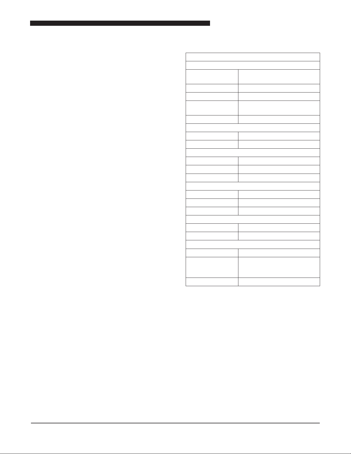
SPECIFICATIONS
MODEL DG2 (SINGLE PHASE – 208 – 240VAC 60Hz
Input Power
Operating Voltage 208VAC to 240VAC, 60Hz
(Plug & Play)
Current
Phase Single
Fuse
Plug NEMA L6-30P twist lock
Output Power
Microwave
Heating Elements 4400W nominal @ 208VAC
Dimensions
Height 24" (60.96cm)
Width 26" (66.04cm)
Depth
Internal Cook Cavity Dimensions
Height 10.5" (26.67cm)
Width 16.75" (42.55cm)
Depth
Weight
Unpacked
Packed 325lbs (147kg)
Clearances
Top 6” (15.2cm)
Sides
Back 0
30A max
Ferraz Shawmut OTM30
(250VAC, 30A)
2020W nominal
32" (81.28cm)
14.75" (37.47cm)
250lbs (113kg)
3" (7.62cm) when next to other
heat sources
.5” (1.3cm) when next to wall
7
Service Manual for DG2 Speed Oven
REMOVAL AND REPLACEMENT OF COMPONENTS
ELECTRICAL LOCKOUT/TAGOUT
PROCEDURE
Before performing any service that
involves electrical connection or disconnection
and/or exposure to electrical components,
always follow the Electrical LOCKOUT/TAGOUT
Procedure. Disconnect all circuits. Failure to
comply can cause property damage, injury
or death.
The Electrical LOCKOUT/TAGOUT Procedure is used
to protect personnel working on an electrical appliance.
Before performing any maintenance or service that
requires exposure to electrical components, follow
these steps:
1. In electrical box, place appliance circuit breaker
into OFF position.
2. Place a lock or other device on electrical box
cover to prevent someone from placing circuit
breaker ON.
3. Place a tag on electrical box cover to indicate
that appliance has been disconnected for service
and power should not be restored until tag is
removed by maintenance personnel.
4. Disconnect appliance power cord from electrical
outlet.
5. Place a tag on the cord to indicate that unit
has been disconnected for service and power
should not be restored until tag is removed by
maintenance personnel.
COVERS AND PANELS
Before performing any service that
involves electrical connection or disconnection
and/or exposure to electrical components,
always follow the Electrical LOCKOUT/TAGOUT
Procedure. Disconnect all circuits. Failure to
comply can cause property damage, injury
or death.
CAUTION: Interior components and surfaces may
be hot if the unit has been in recent use.
Top Panel
Before performing any service that
involves electrical connection or disconnection
and/or exposure to electrical components,
always follow the Electrical LOCKOUT/TAGOUT
Procedure. Disconnect all circuits. Failure to
comply can cause property damage, injury
or death.
1. Remove the unit from its power source and follow
the proper Lockout/Tagout procedures.
2. Remove all of the sheet metal screws that secure
the Top Panel to the unit. Set aside for reuse.
3. Remove the Top Panel to gain access to the control
components.
Side Panels
Before performing any service that
involves electrical connection or disconnection
and/or exposure to electrical components,
always follow the Electrical LOCKOUT/TAGOUT
Procedure. Disconnect all circuits. Failure to
comply can cause property damage, injury
or death.
1. Remove the unit from its power source and follow
the proper Lockout/Tagout procedures.
2. Remove the Top Panel as described in the Top
Panel removal section.
3. Remove the screws securing the Side Panels.
Retain for reuse.
4. Removing the Side Panels provides access to
components not accessible from the rear of the unit.
Rear Panel Exhaust Vent Covers
Before performing any service that
involves electrical connection or disconnection
and/or exposure to electrical components,
always follow the Electrical LOCKOUT/TAGOUT
Procedure. Disconnect all circuits. Failure to
comply can cause property damage, injury
or death.
8
Service Manual for DG2 Speed Oven
Louvered
Rear
Service Panel
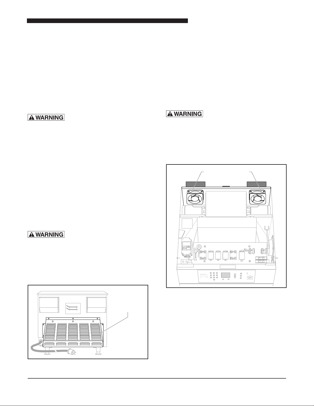
Rear Exhaust Fans
The oven is equipped with two circulating fans mounted
on the rear panel. An exhaust vent cover is mounted
over each fan. These must be removed to gain access
to the fans.
1. Remove the unit from its power source and follow
the proper Lockout/Tagout procedures.
2. Remove the four screws securing each Exhaust
Vent Cover. Retain for reuse.
Rear Heater Cover
Before performing any service that
involves electrical connection or disconnection
and/or exposure to electrical components,
always follow the Electrical LOCKOUT/TAGOUT
Procedure. Disconnect all circuits. Failure to
comply can cause property damage, injury
or death.
The Rear Heater Cover provides access to the heat
elements.
1. Remove the unit from its power source and follow
the proper Lockout/Tagout procedures.
Removing the Louvered Rear Service Panel provides
access to the High Voltage components.
1. Remove the unit from its power source and
follow the proper Lockout/Tagout procedures.
2. Remove the screws securing the Louvered
Rear Panel to the back of the oven. Set aside
for reuse.
EXHAUST FANS
Before performing any service that
involves electrical connection or disconnection
and/or exposure to electrical components,
always follow the Electrical LOCKOUT/TAGOUT
Procedure. Disconnect all circuits. Failure to
comply can cause property damage, injury
or death.
2. Remove the screws securing the Rear Heater
Element Cover.
Louvered Rear Service Panel
Before performing any service that
involves electrical connection or disconnection
and/or exposure to electrical components,
always follow the Electrical LOCKOUT/TAGOUT
Procedure. Disconnect all circuits. Failure to
comply can cause property damage, injury
or death.
Location of Louvered Rear Service Panel
Location of Rear Exhaust Fans
The exhaust fans are mounted on the rear panel of
the unit.
Testing
The Exhaust Fans operate when the Cooling Thermostat
detects a temperature of 130°F (55°C) in the electrical
compartment of the oven. The oven must be plugged in
and turned on to test for fan operation. If both fans do not
operate after the oven has been warmed up for several
minutes, the Cooling Thermostat should be checked.
9
Service Manual for DG2 Speed Oven
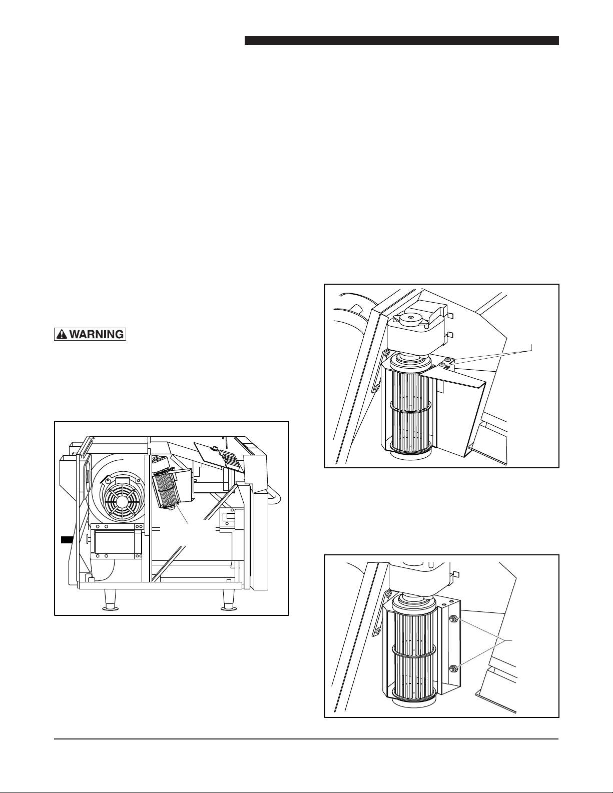
Tangential
Blower
Remove
screws
Remove
nuts
Exhaust Fan Replacement
1. Remove the unit from its power source and follow
the proper Lockout/Tagout procedures.
2. Remove the Top Cover.
3. Remove the Exhaust Vent Cover/s.
4. Tag and disconnect the exhaust fan wires.
5. Remove the screws and nuts securing the fan to
the panel. Retain these for reuse.
6. Remove the fan.
7. Reverse procedure to install the replacement fan.
8. Restore the unit to service and check for proper
fan operation.
9. Reattach Exhaust Vent Covers and Top Panel.
LEFT SIDE TANGENTIAL BLOWER
Before performing any service that
involves electrical connection or disconnection
and/or exposure to electrical components, always
follow the Electrical LOCKOUT/TAGOUT Procedure.
Disconnect all circuits. Failure to comply can
cause property damage, injury or death.
the electrical compartment of the oven. The oven must
be plugged in and turned on to test for blower operation.
If blower and other cooling fans do not operate after
the oven has been warmed up for several minutes, the
Cooling Thermostat should be checked.
Tangential Blower Replacement
1. Remove the unit from its power source and follow
the proper Lockout/Tagout procedures.
2. Remove the Top Panel.
3. Remove the Left Side Panel.
4. Tag and disconnect the blower wires.
5. Remove the two screws securing duct to the
blower assembly. Set aside for reuse.
Location of Tangential Blower
The Tangential Blower is located on the left side of
the oven.
Testing
The Tangential Blower operates when the Cooling
Thermostat detects a temperature of 130°F (55°C) in
10
6. Remove the duct to gain access to the Tangential
Blower assembly mounting screws.
7. Remove the two nuts securing the Tangential
Blower assembly to the bracket and remove the
blower assembly.
Service Manual for DG2 Speed Oven
Right Side
Cooling Fan
Solid State Relays
8. Reverse this procedure to install a new Tangential
Blower assembly.
9. Restore the unit to service and check for proper
operation.
10. Reattach all panels and covers.
RIGHT SIDE COOLING FAN
Before performing any service that
involves electrical connection or disconnection
and/or exposure to electrical components,
always follow the Electrical LOCKOUT/TAGOUT
Procedure. Disconnect all circuits. Failure to
comply can cause property damage, injury
or death.
3. Tag and disconnect the Cooling Fan wires.
4. Remove the screws and nuts that secure the
Cooling Fan to the right side panel. Retain for
use later.
5. Remove the Cooling Fan.
6. Reverse procedure to install the replacement fan.
7. Restore the unit to service and check for proper
operation.
8. Reattached all panels and covers.
SOLID STATE RELAYS
Before performing any service that
involves electrical connection or disconnection
and/or exposure to electrical components,
always follow the Electrical LOCKOUT/TAGOUT
Procedure. Disconnect all circuits. Failure to
comply can cause property damage, injury
or death.
Location of Right Side Cooling Fan
Testing
The right side Cooling Fan operates when the Cooling
Thermostat detects a temperature of 130°F (55°C) in the
electrical compartment of the oven. The oven must be plugged
in and turned on to test for fan operation. If the fan does not
operate after the oven has been warmed up for several
minutes, the Cooling Thermostat should be checked.
Right Side Cooling Fan Replacement
1. Remove the unit from its power source and follow
2. Remove the Top Panel.
the proper Lockout/Tagout procedures.
Location of Solid State Relays
The Solid State Relays are located on the Electrical
Mounting Panel in the top front of the unit. There are
two Solid State Relays. The left side SSR controls the
power supply to the High Voltage Transformers and the
right side SSR controls the Heat Elements.
Operational Testing
The Solid State Relays are equipped with an LED that
illuminates when input voltage is provided to the relay.
Input voltage will only occur if the oven is turned ON
and the door is closed. If the LED does not illuminate,
test the inputs to the relay using a volt meter. 12 VDC
should be present when switched on by the control. If
voltage is not present check the door switches.
11
Service Manual for DG2 Speed Oven
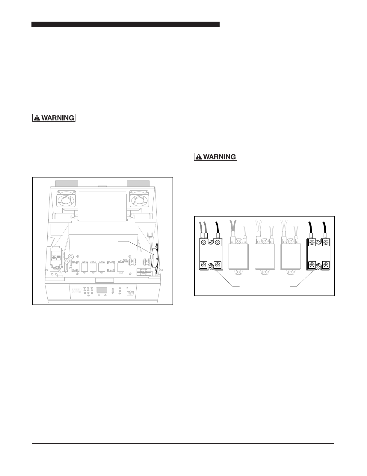
Mechanical Relays
Primary Monitor
Secondary
Tap Switch
Relay
Solid State Relay Replacement
1. Remove the unit from its power source and follow
the proper Lockout/Tagout procedures.
2. Remove the Top Panel.
3. Tag and disconnect the wires to the defective Solid
State Relay.
4. Remove the defective relay.
5. Install the replacement Solid State Relay.
6. Refer to the tags or the schematic and reconnect
all of the wires.
7. Attach all covers and panels.
8. Restore power to the unit and test for proper relay
operation.
MECHANICAL RELAYS
Before performing any service that
involves electrical connection or disconnection
and/or exposure to electrical components,
always follow the Electrical LOCKOUT/TAGOUT
Procedure. Disconnect all circuits. Failure to
comply can cause property damage, injury
or death.
Switch. The relay on the right side is connected to the
Secondary Oven Door Switch. When the Oven Door
is closed, the Primary Relay and the Secondary Relay
are activated allowing power to the Magnetron circuit.
The Monitor Relay is open when the door is closed and
closed when the door is open. When the door is closed
both the Primary and Secondary Relays must activate
before power is provided to the Magnetron circuit. The
Monitor Relay will short out causing the fuse to open if
it closes at the same time or after as the Primary and
Secondary Relays.
Mechanical Relay Replacement
1. Remove the unit from its power source and follow
the proper Lockout/Tagout procedures.
2. Remove the top panel
3. Tag and disconnect the defective relay’s wires.
4. Remove the defective relay.
5. Install the new Mechanical Relay.
6. Restore power to the unit and test for proper
operation.
7. Remove power and reattach all covers and panels.
8. Restore Power to the unit.
Location of Mechanical Relays
The Mechanical Relays are located on the top front
of the unit.
Operational Testing
The Mechanical Relays provide safety for the Magnetron
and Heater Power circuits. The relays require 24 VDC
input voltage for the contacts to close. The relays are
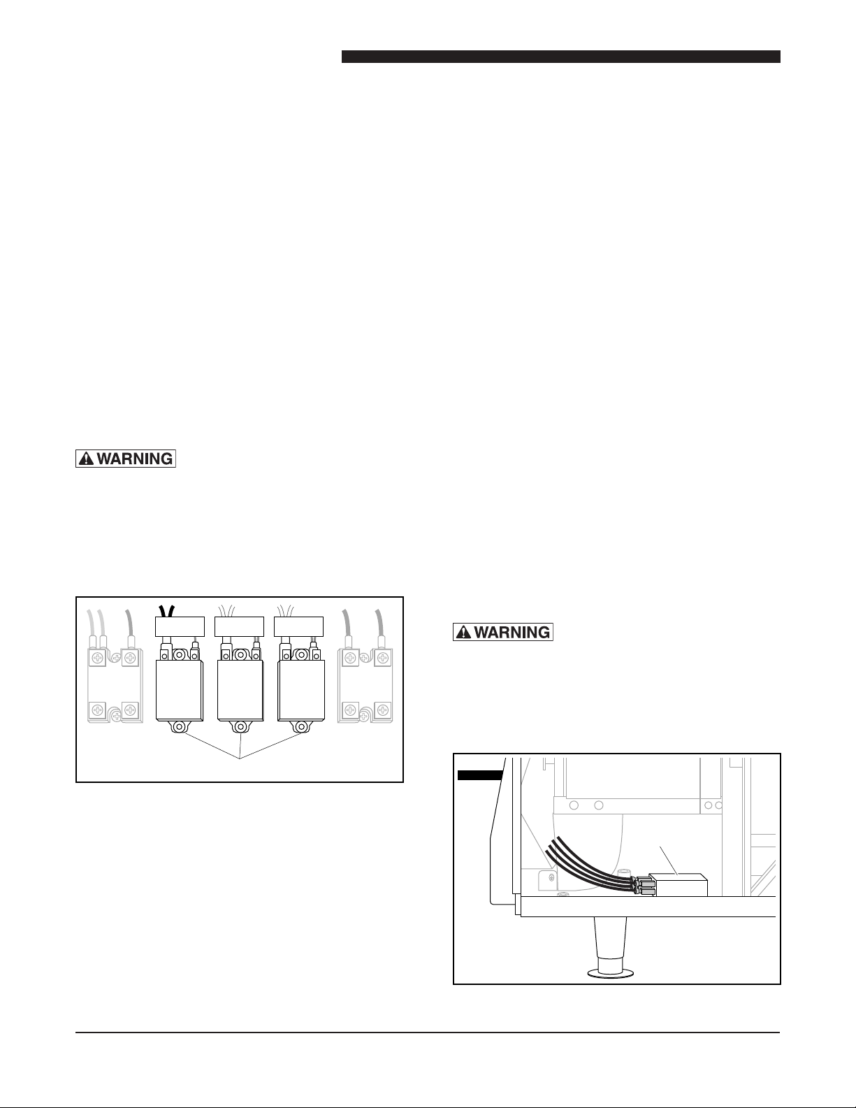
connected to the three separate door switches. The
relay at the left in the image above is connected to
the Primary Oven Door Switch. The relay in the center
of the image is connected to the Monitor Oven Door
TAP SWITCH RELAY
Before performing any service that
involves electrical connection or disconnection
and/or exposure to electrical components, always
follow the Electrical LOCKOUT/TAGOUT Procedure.
Disconnect all circuits. Failure to comply can
cause property damage, injury or death.
Location of Tap Switch Relay
12
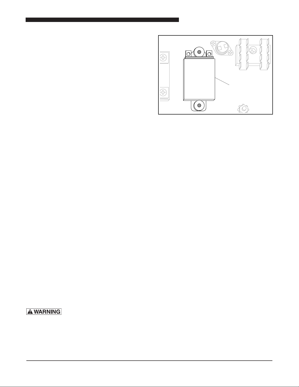
The Tap Switch Relay is located on the lower left side
Heater Relay
towards the rear of the unit.
Operation and Testing
The Tap Switch relay is connected to the output of
the DC power supply. The power supply provides a
24 VDC signal from the control board for the 208VAC
supply condition. For 240VAC, the mechanical relay is
not triggered. After plugging the unit into a rated power
source, the control board determines if the supply source
holds a voltage of either above or below 220VAC.
Voltages above 220VAC are considered the default
condition (no relay switching occurs). The 240VAC
yellow tap wire remains active on the high voltage
transformer. Voltages below 220V cause the mechanical
relay to switch to the blue tap wire to 208VAC on the
high voltage transformer tap.
To test, disconnect the oven from power. It must be
disconnected each time it is tested so the Tap Relay
returns to its default state. When connected to a 240VAC
supply, the Tap Relay should remain in the default state.
When tested with a 208VAC supply the Tap Relay
should switch to the 208VAC (blue wire) within three
seconds of the oven being turned on.
Replacing the Tap Relay
1. Remove the unit from its power source and follow
the proper Lockout/Tagout procedures.
2. Remove the top and left side panels
3. Tag and disconnect the Tap Switch Relay wires.
Service Manual for DG2 Speed Oven
Location of Heater Relay
The Heater Relay is located on the control component
panel above the cavity.
Operational Testing
The mechanical relay is controlled by the primary door
switch in conjunction with the primary interlock relay.
When the oven door is closed, the primary switch is
closed. Closing the primary and the heater relay allows
heater operation. When the door is opened, the primary
and heater relays are also open.
To test the Heater Relay, label and remove the supply
wires to the Heater Relay. Close the oven door and
check for continuity across the Heater Relay output
terminals. With the door open there should be no
continuity across the Heater Relay output terminals.
4. Remove the faulty relay.
5. Install the replacement relay.
6. Temporarily power up unit and ensure relay is
working as designed.
7. Remove unit from its power source and reattach
all panels and covers.
8. Restore unit to its power source.
HEATER RELAY
Before performing any service that
involves electrical connection or disconnection
and/or exposure to electrical components,
always follow the Electrical LOCKOUT/TAGOUT
Procedure. Disconnect all circuits. Failure to
comply can cause property damage, injury
or death.
Heater Relay Replacement
1. Remove the unit from its power source and follow
the proper Lockout/Tagout procedures.
2. Tag and disconnect the Heater Relay wires.
3. Remove the Heater Relay.
4. Install the replacement Heater Relay.
5. Referring to the tags, reconnect the relay wires.
6. Restore power to the unit and verify that the Heater
Relay is working properly.
7. Remove power from the unit and reattach all panels
and covers.
8. Restore power to the unit.
13
Service Manual for DG2 Speed Oven
Line
Fuses
Cabinet
Overheat
Protection
Switch
LINE FUSES
Before performing any service that
involves electrical connection or disconnection
and/or exposure to electrical components, always
follow the Electrical LOCKOUT/TAGOUT Procedure.
Disconnect all circuits. Failure to comply can
cause property damage, injury or death.
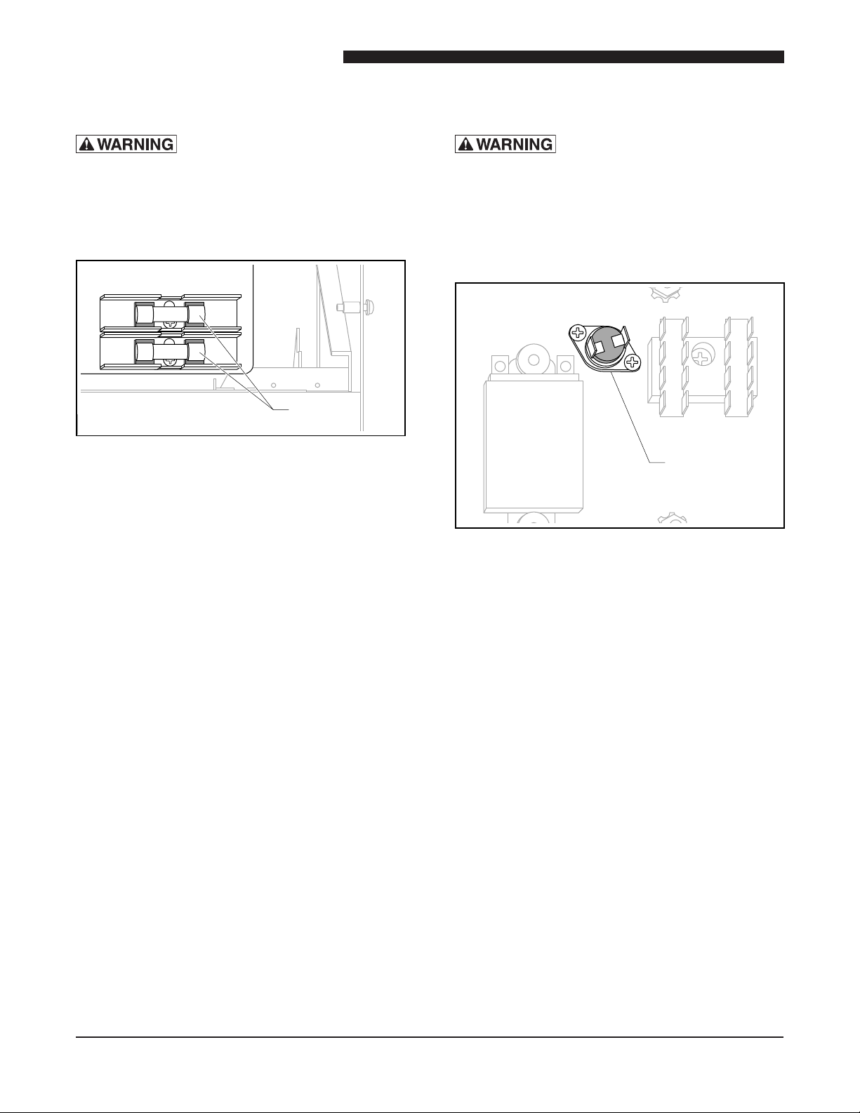
Location of Line Fuses
The line fuses are components of the supply circuit for
all components except the cooling fans, magnetron
cooling fan, and cooling thermostat. They are located
in the fuse clips on the upper right side of the electrical
component panel.
Line Fuse Replacement
1. Remove the unit from its power source and follow
the proper Lockout/Tagout procedures.
2. Remove the top panel.
3. Remove both fuses.
4. Perform a continuity test on both fuses.
5. Replace the faulty fuse/s.
6. Restore the unit to its power source
7. Ensure the unit is operating correctly.
8. Remove power from unit and reattach top panel.
9. Restore power to the unit.
Note: If the fuse/s open again, the interlock switches
and relays should be checked for proper operation.
Any damaged or non-functional relays should be
replaced.
CABINET OVERHEAT PROTECTION SWITCH
Before performing any service that
involves electrical connection or disconnection
and/or exposure to electrical components,
always follow the Electrical LOCKOUT/TAGOUT
Procedure. Disconnect all circuits. Failure to
comply can cause property damage, injury
or death.
Location of Cabinet Overheat
Protection Switch
The Cabinet Overheat Protection switch is located on
the Control Board on top of the unit.
Operational Testing
The thermostat opens when a temperature exceeds
190°F (88°C) around the top control component panel.
The thermal switch resets automatically when the
ambient temperature around the control component
panel drops below 172°F (78°C).
The switch is normally closed at ambient room
temperature. DO NOT attempt to overheat this switch
while installed in the unit as this may cause permanent
damage to components mounted on the component
panel. All testing should be done outside of the unit.
Cabinet Overheat Protection Switch
Replacement
14
1. Remove the unit from its power source and follow
the proper Lockout/Tagout procedures.
2. Remove the top panel.
3. Tag and disconnect the Overheat Protections
Switch (thermostat) wires.
4. Install the replacement thermostat.
Control Board
Mounting
Screws
Signal
Transformer
5. Refer to the tags and reconnect the thermostat
wiring.
6. Briey restore power to the unit and ensure it is
operating correctly.
7. Remove the unit from its power source and reattach
the top panel.
8. Restore power to the unit.
Service Manual for DG2 Speed Oven
CONTROL BOX ASSEMBLY
Before performing any service that
involves electrical connection or disconnection
and/or exposure to electrical components, always
follow the Electrical LOCKOUT/TAGOUT Procedure.
Disconnect all circuits. Failure to comply can
cause property damage, injury or death.
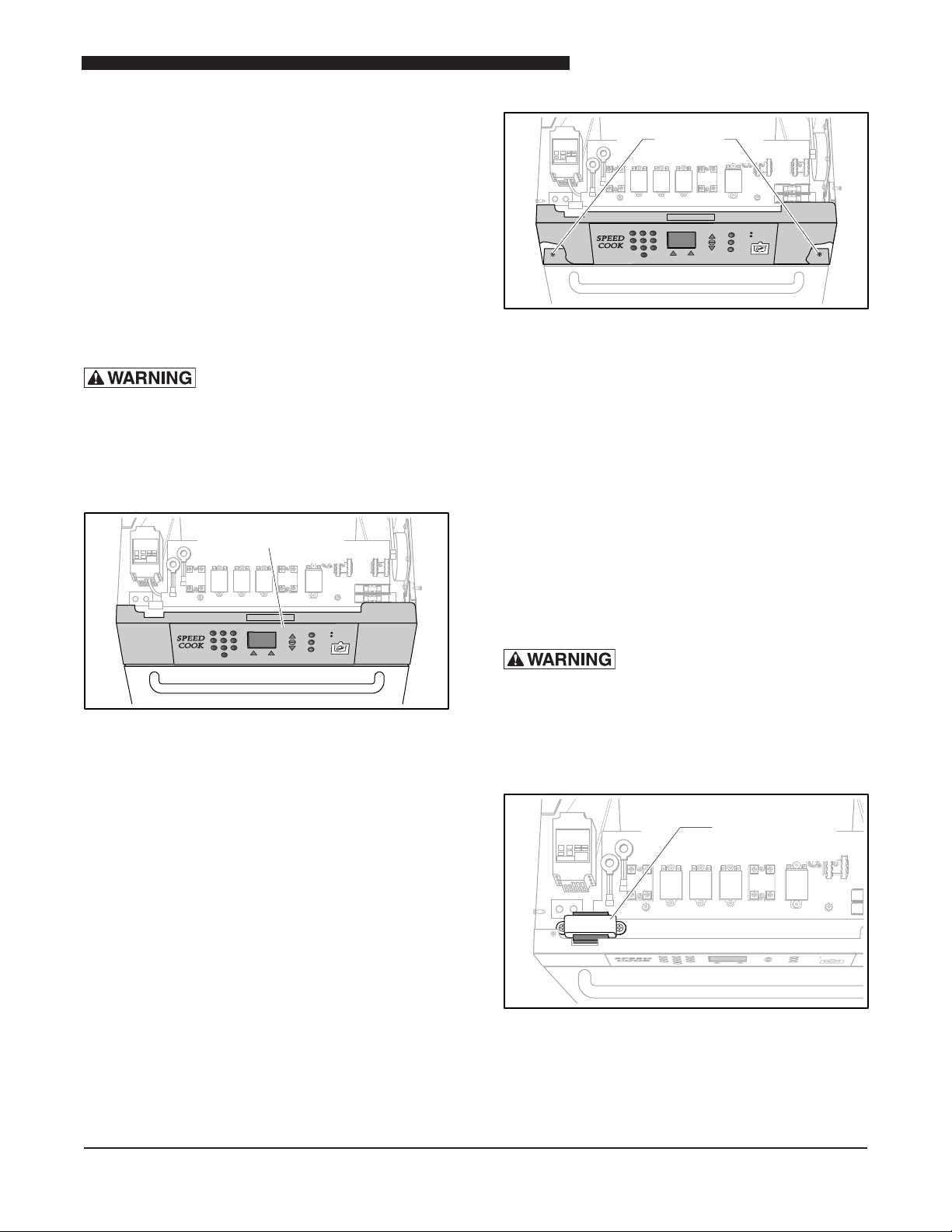
Speed Oven Control Board
The Control Board is mounted on the front of the unit.
Control Box Assembly Mounting Screws
4. Remove the faulty Control Box Assembly.
5. Install the replacement Control Box Assembly.
6. Referring to the tags, reconnect all of the Control
Board wires.
7. Temporarily restore power to the unit and verify
the Control Board is operating correctly.
8. Remove the unit from its power source and reattach
the top panel.
9. Restore the unit to its power source.
SIGNAL TRANSFORMER
Before performing any service that
involves electrical connection or disconnection
and/or exposure to electrical components, always
follow the Electrical LOCKOUT/TAGOUT Procedure.
Disconnect all circuits. Failure to comply can
cause property damage, injury or death.
System Testing
See the section on General Systems Testing in the
System Testing Section of the Manual for full details
on testing Control Board.
Control Board Replacement
1. Remove the unit from its power source and follow
the proper Lockout/Tagout procedures.
2. Tag and disconnect wires to the Control Board.
3. Remove the Control Box Assembly mounting
screws.
Location of Signal Transformer
The Signal Transformer is located on the upper left side
of the oven just behind the Control Panel.
The Signal Transformer provides low voltage to the
Control Panel.
15
Service Manual for DG2 Speed Oven
Monitor
Switch
Primary
Interlock
Switch
OVEN FRONT
Control
Switch
Secondary
Interlock
Switch
OVEN FRONT
Operational Testing
With a 208 / 240 VAC on the Primary winding (input),
the measured voltage across the entire Secondary
winding (output) should be approximately 24 VAC.
The voltage across either outer terminal and middle
terminal should be approximately 12 VAC.
A short to ground can be measured by testing for
continuity between each individual terminal and ground.
1. Remove the unit from its power source and follow
the proper Lockout/Tagout procedures.
2. Remove the top panel.
3. Tag and disconnect Signal Transformer wires.
4. Remove the Signal Transformer.
5. Install the replacement Signal Transformer.
6. Briey restore power to the unit and ensure the
Control Panel is operating.
7. Remove the unit from its power source and reattach
the top panel.
8. Restore the unit to its power source and ensure it
is operating properly.
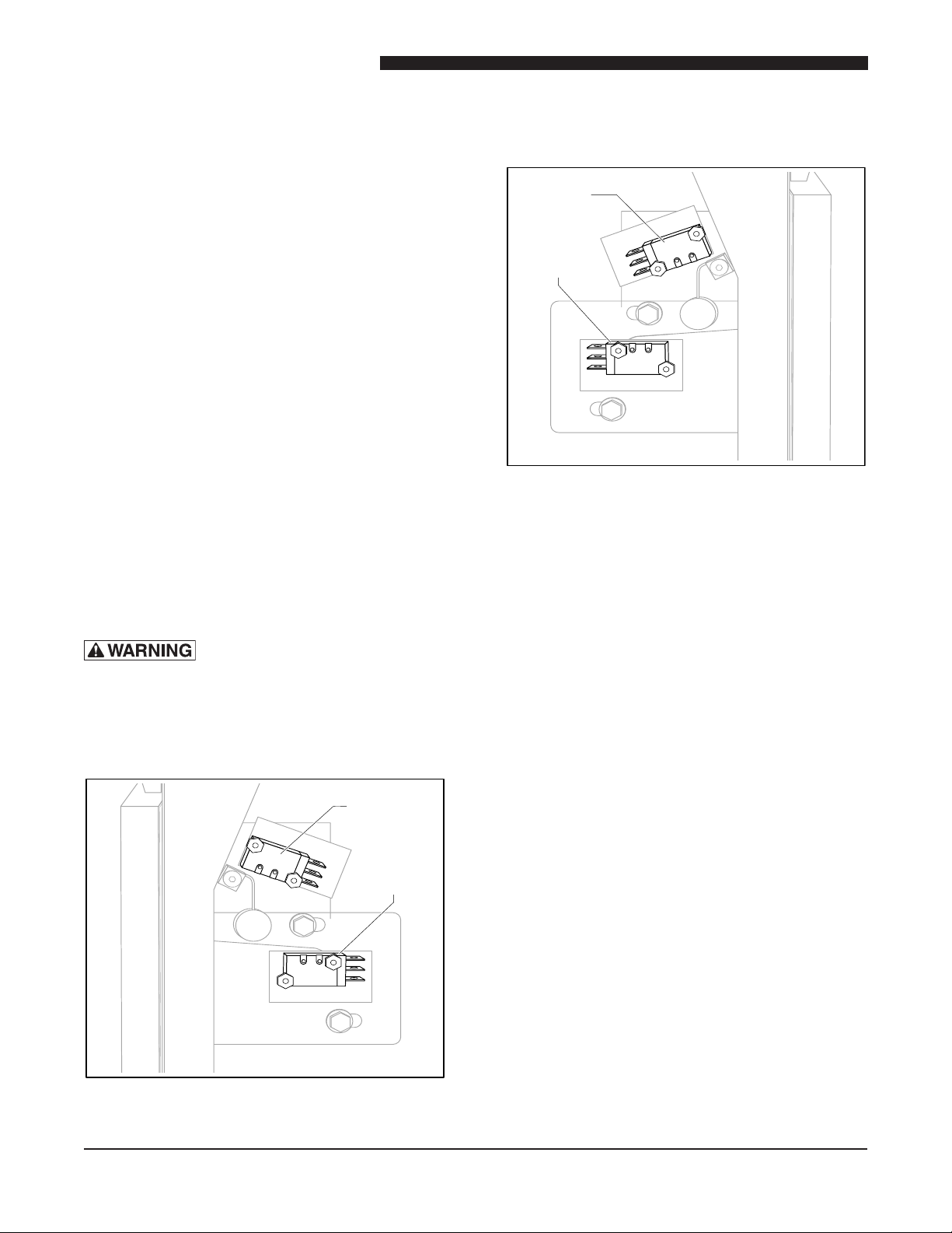
The Monitor Switch and Primary Interlock switches are
located on the upper right side of the unit.
Location of the Secondary Interlock
and Control Switches
The Secondary Interlock and Control switches are
located on the upper left side of the unit.
DOOR SWITCHES
Before performing any service that
involves electrical connection or disconnection
and/or exposure to electrical components, always
follow the Electrical LOCKOUT/TAGOUT Procedure.
Disconnect all circuits. Failure to comply can
cause property damage, injury or death.
Operational Testing
The Primary Interlock, Secondary Interlock and Door
switches are normally closed when the door is closed.
The Monitor Switch is normally open when the door
is closed.
Switch Replacement
1. Remove the unit from its power source and follow
the proper Lockout/Tagout procedures.
2. Remove the top and both side panels.
3. Test for proper switch operation.
4. Tag and disconnect the faulty switch’s wires.
5. Remove the faulty switch.
6. Install the replacement switch.
7. Restore power to the unit, and test for proper switch
operation.
8. Remove power from the unit and reattach all covers
and panels.
9. Restore power to the unit.
16
10. Perform a Microwave Leakage Test (as described
on page 31) to validate proper functionality.
Location of the Monitor and Primary
Interlock Switches
Service Manual for DG2 Speed Oven
Auxiliary
Thermal
Cutout
Switch
Thermal
Cutout
Switch
Heating Elements
THERMAL CUTOUTS
Before performing any service that
involves electrical connection or disconnection
and/or exposure to electrical components,
always follow the Electrical LOCKOUT/TAGOUT
Procedure. Disconnect all circuits. Failure to
comply can cause property damage, injury
or death.
Thermal Cutout Replacement
1. Remove the unit from its power source and follow
the proper Lockout/Tagout procedures.
2. Remove the top and right side panels.
3. Tag and disconnect the faulty Thermal Cutout
switch wires.
4. Remove the faulty Thermal Cutout switch.
5. Reverse this procedure to install the new Thermal
Cutout switch.
6. Restore the unit to its power source and check for
proper operation.
7. Remove the unit from its power source and reattach
all covers and panels
8. Restore power to the unit.
HEATING ELEMENTS
Before performing any service that
involves electrical connection or disconnection
and/or exposure to electrical components,
always follow the Electrical LOCKOUT/TAGOUT
Procedure. Disconnect all circuits. Failure to
comply can cause property damage, injury
or death.
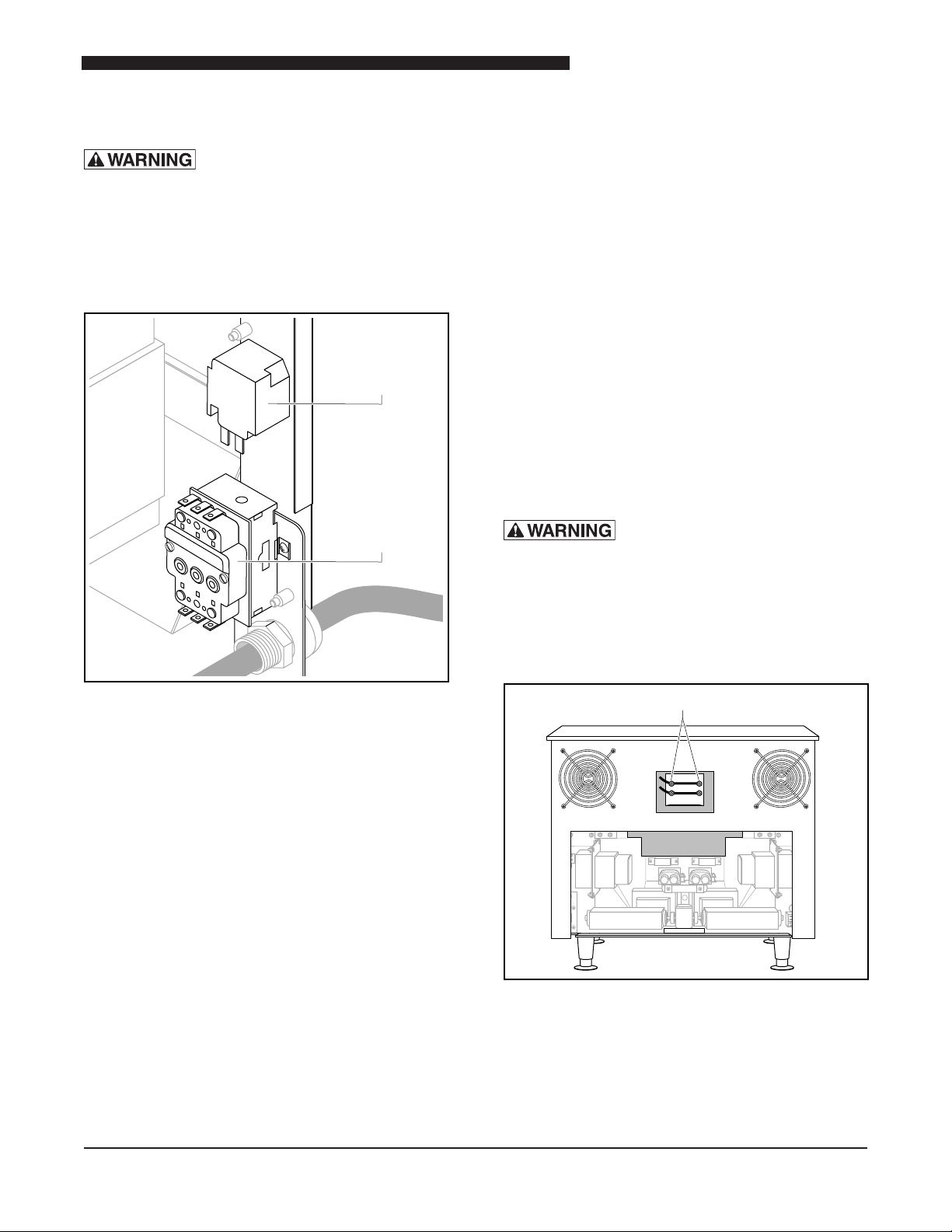
Location of Thermal Cutout Switches
The Thermal Cutout Switch (Hi Limit) and Auxiliary
Cutout Switch are located on the rear of the unit just
above the power cord strain relief.
Operational Testing
The main Thermal Cutout Switch remains closed until
the oven reaches 572°F (300°C) The Auxiliary Switch
opens when the oven cavity reaches 525°F (274°C).
The main Thermal Cutout Switch must be manually
reset. The temperature must drop below 500°F (260°C)
before a reset can be attempted. Test the Thermal
Cutouts for continuity in ambient temperature. The
Thermal Cutout must be reset before attempting the
test. If the test fails the unit is faulty.
Location of Heating Elements
Testing Procedures
Disconnect the wires from the Heating Elements. Test
both elements using an Ohm meter. Each element
should read approximately 19.7Ω.
17
 Loading...