

Duke ADI-1E-SW Service Manual
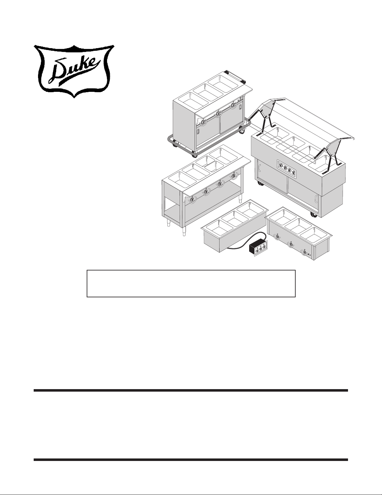
ELECTRIC
SEALED WELL
FOOD WARMERS
MODELS
THURMADUKE STEAM TABLES
THURMADUKE SERVING SYSTEMS
AEROHOT SEALED WELL MODELS
AEROSERV SERVING SYSTEMS
Service Manual
HERITAGE HOT FOOD ELECTRIC BUFFET
NEXT GENERATION ELECTRIC HOT FOOD
SERVING SYSTEMS
Please read this manual completely before attempting
to install, operate or service this equipment
This document is prepared for trained Duke service technicians. It is not to be used by anyone not
properly qualied to perform these procedures.
This Service Manual is not all encompassing. If you have not been trained on servicing this product,
be sure to read the manual completely before attempting servicing. Be sure all necessary tools, test
equipment, and skills are available. Those procedures for which you do not have the proper skills
and test equipment must be performed only by a qualied Duke trained service technician.
Written consent from Duke is required to reproduce any portion of this Manual. Unauthorized
reproduction is prohibited.
Duke Manufacturing Company
Broadway • St. Louis, MO 63102
800.735.3853 • 314.231.1130
www.dukemfg.com
P/N 219219B
Service Manual for Electric Sealed Well Food Warmers
IMPORTANT WARNING AND SAFETY INFORMATION
WARNING
READ THIS MANUAL THOROUGHLY BEFORE OPERATING, INSTALLING, OR
PERFORMING MAINTENANCE ON THE EQUIPMENT.
WARNING
FAILURE TO FOLLOW INSTRUCTIONS IN THIS MANUAL CAN CAUSE PROPERTY
DAMAGE, INJURY OR DEATH.
WARNING
DO NOT STORE OR USE GASOLINE OR OTHER FLAMMABLE VAPORS OR
LIQUIDS IN THE VICINITY OF THIS OR ANY OTHER APPLIANCE.
WARNING
DO NOT OPERATE THIS EQUIPMENT WITHOUT PROPERLY PLACING AND
SECURING ALL COVER AND ACCESS PANELS.
CAUTION
Observe the following:
• Provide and maintain adequate minimum clearances from all walls and combustible materials.
• Provide and maintain adequate clearance for air openings.
• Keep the equipment area free and clear of combustible material.
• Operate equipment only on the type of electricity indicated on the specication plate.
• Retain this manual for future reference.
2

Service Manual for Electric Sealed Well Food Warmers
TABLE OF CONTENTS
SPECIFICATIONS .............................................................................................................. 4
INSTALLATION .................................................................................................................. 4
Location ......................................................................................................................... 4
Leveling .......................................................................................................................... 4
Stabilizing ....................................................................................................................... 4
Electrical Connection ..................................................................................................... 4
PARTS REPLACEMENT .................................................................................................... 5
Innite Switch Replacement ........................................................................................... 5
Aerohot Sealed Well Models, AeroServ Serving System, Heritage Hot Food
Electric Buffet and Next Generation Electric Hot Food Serving System ................... 5
Aerohot ADI1SW through ADI5SW Models ............................................................... 6
Electronic Thermostat Replacement .............................................................................. 6
Aerohot ASI1SW through ASI5SW Models ............................................................... 6
Thurmaduke Steam Tables and Thurmaduke Serving Systems ............................... 7
Indicator Lamp Replacement ......................................................................................... 8
Power Toggle Switch Replacement – Thurmaduke Models ........................................... 9
Element Replacement .................................................................................................... 9
Hi-Limit Thermostat Replacement ............................................................................... 10
Carving Board Shelf Replacement ................................................................................11
Caster Replacement – Thurmaduke Serving System, AeroServ and
Heritage Models ...................................................................................................... 12
Push Bar Replacement – Thurmaduke Serving System .............................................. 12
Master Drain Valve Replacement ................................................................................ 13
SERVICE INFORMATION ................................................................................................ 15
Troubleshooting Procedure .......................................................................................... 15
MAINTENANCE ............................................................................................................... 16
Stainless Steel Care and Cleaning .............................................................................. 16
Care and Cleaning – Painted and Powder Coated Units ............................................. 16
SCHEMATICS .................................................................................................................. 17
3
Service Manual for Electric Sealed Well Food Warmers
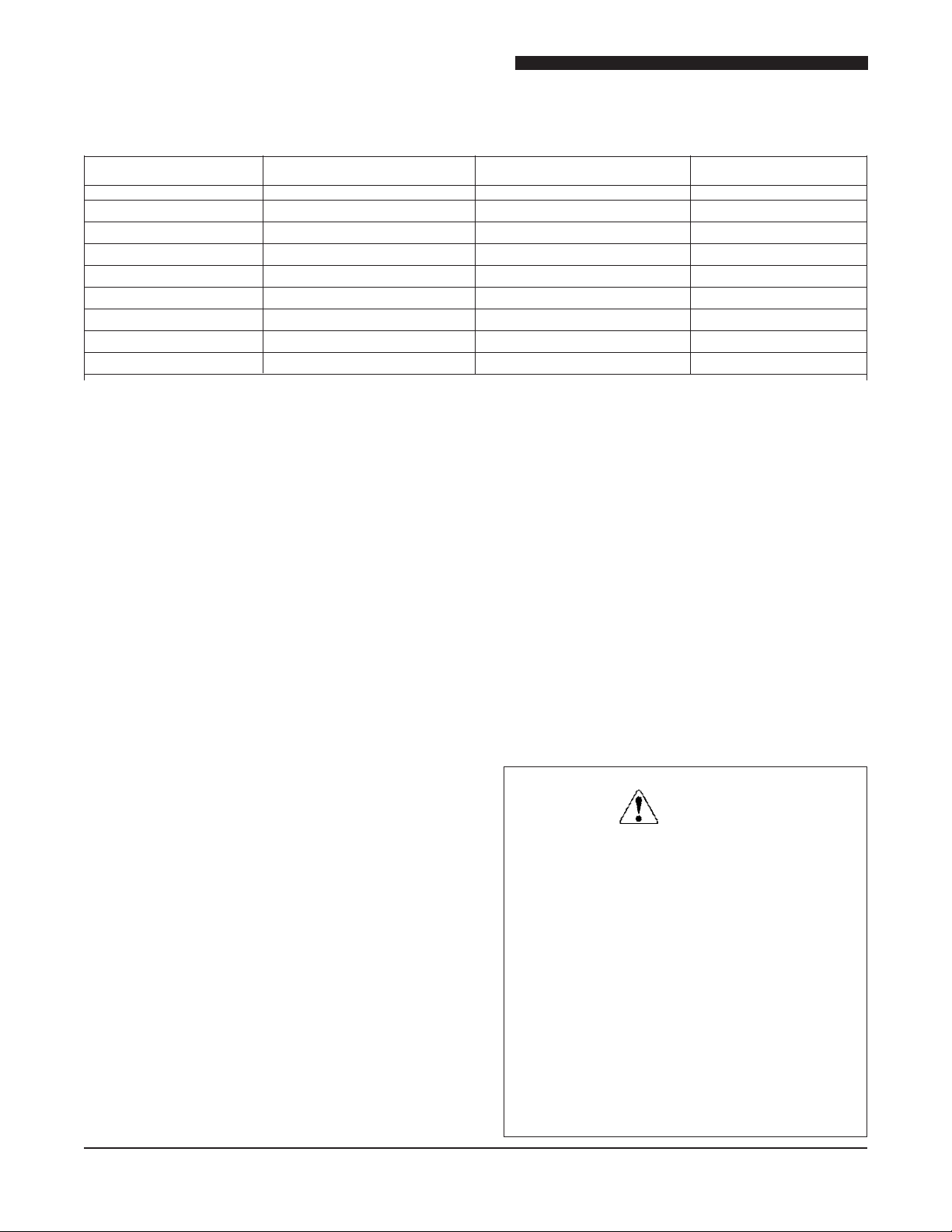
SPECIFICATIONS
MODEL DESCRIPTION VOLTAGE SIZE
E302SW – E305SW Aerohot Sealed Well 115VAC, 208VAC & 236VAC Variable 2 well to 5 well
ADI1ESW – ADI5ESW Aerohot Drop-in Sealed Well 115VAC, 208VAC & 236VAC Variable 1 well to 5 well
ASI1ESW – ASI5ESW Aerohot Slide-in Sealed Well 115VAC, 208VAC & 236VAC Variable 1 well to 5 well
E-2-CBSS – E-6-CBSS Stainless Steel Thurmaduke 115VAC, 208VAC & 236VAC Variable 2 well to 6 well
E-2-CBPG – E-6-CBPG Painted Thurmaduke 115VAC, 208VAC & 236VAC Variable 2 well to 6 well
E302-25 – E305-25 AeroServ Serving System 115VAC, 208VAC & 236VAC Variable 2 well to 5 well
HB2HF – HB5HF Heritage Buffet 115VAC, 208VAC & 236VAC Variable 2 well to 5 well
TEHF-32 – TEHF88 Thurmaduke Serving System 115VAC, 208VAC & 236VAC Variable 2 well to 6 well
NG32HF – NG74HF Next Generation Hot Food 115VAC, 208VAC & 236VAC Variable 2 well to 5 well
INSTALLATION
Location
The food warmers represented in this manual are
intended for indoor use only. Be sure the chosen
location has a oor strong enough to support
the total weight of the unit fully loaded with food
product. Reinforce the oor (stationary units) or
cabinet (drop-in or slide-in units) if necessary to
provide for maximum loading. Portable units (units
with optional casters) should be placed on a level
surface capable of supporting the unit’s fully loaded
weight. For the most efcient operation, be sure to
provide good air circulation inside and out.
Leveling
Be sure oor units are placed on a rm, at surface/
oor. Check for cracks in ooring or tile and avoid
these areas if possible. If necessary place support
pads, properly rated for the weight of the unit, to
“bridge” uneven or cracked ooring. Level the unit
accordingly using the leg adjusters.
Make sure the top of the cabinet is level before
installing Aerohot drop-in or slide-in units. It may
be necessary to shim the unit or cabinet to make
it level.
Stabilizing
Use the leg adjustments to ensure that the unit
is solid to the oor surface at all contact points.
Ensure that the unit does not rock when pressure
is applied to the top corners. Units with casters
will require spacers to make them level on uneven
surfaces. The spacers should be placed under the
locking casters for maximum stability. Casters must
be locked when the unit is in service.
Electrical Connection
The Electric Sealed Well Food Warmers are
available as 115VAC, 208VAC, or 236VAC,
50/60 Hz. Portable units are available with a
properly rated and wired cord. Direct wiring of
units to the power supply must be performed by
a certied electrician and must comply with local
electrical codes for your municipality.
WARNING:
REFER TO THE AMPERAGE DATA
LIST IN THE SPECIFICATIONS OR
THE SERIAL TAG DATA AND YOUR
LOCAL CODE OR THE NATIONAL
ELECTRICAL CODE TO BE SURE UNIT
IS CONNECTED TO THE PROPER
POWER SOURCE. A PROTECTED
CIRCUIT OF THE CORRECT VOLTAGE
AND AMPERAGE MUST BE RUN FOR
CONNECTION OF THE SUPPLY CORD
OR PERMANENT CONNECTION TO THE
UNIT. THE POWER MUST BE TURNED
OFF AND DISCONNECTED WHENEVER
PERFORMING MAINTENANCE OR
REPAIR FUNCTIONS.
4
PARTS REPLACEMENT
D1022
D1023
Knob
Guard
Locking
Nut
Infinite
Switch
D1024
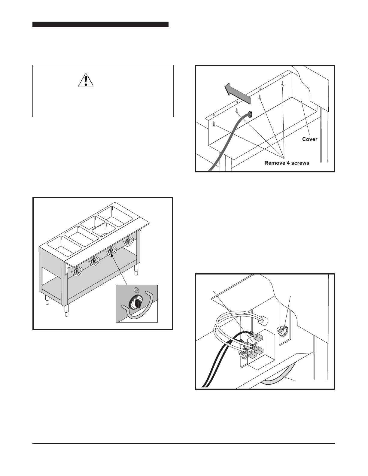
WARNING
ALWAYS DISCONNECT THE UNIT
FROM ITS POWER SOURCE BEFORE
SERVICING.
INFINITE SWITCH REPLACEMENT
Aerohot Sealed Well Models, AeroServ
Serving System, Heritage Hot Food Electric
Buffet and Next Generation Electric Hot
Food Serving System
Service Manual for Electric Sealed Well Food Warmers
Figure 2. Removing bottom cover
2. Remove the screws that hold the bottom cover
in place (see Figure 2).
Figure 1. Location of Innite Switch
Innite switches are located on the operator’s side
of the unit. Each switch is located directly below its
corresponding pan. Figure 1 depicts the location
of the switches on most sealed well units.
3. Slide the bottom cover toward the back of the
unit. Provide support for it to prevent damage
to the wiring harness.
Note: Tag the power cable wires and disconnect
them. Doing this allows for complete removal of
the bottom cover.
1. Disconnect unit from power source.
Figure 3. View of innite switch wiring.
4. Tag and disconnect the innite switch wiring.
An example of the innite switch wiring is seen
in Figure 3.
5
Service Manual for Electric Sealed Well Food Warmers
Remote Infinite Switch
D1025
Thermostats
D1026
5. Remove the knob.
6. Remove the two screws that secure the innite
switch to the panel.
7. Remove the switch from the back of the
panel.
8. Install replacement innite switch, mounting
screws and knob.
9.
Reference the tags to reconnect the wires to
the innite switch.
10.
Reconnect the power wiring and reinstall the
bottom cover.
11.
Connect the unit to its power source.
Aerohot ADI1SW through ADI5SW Models
5. Tag and disconnect the innite switch wiring.
Wiring is depicted in Figure 3.
6. Remove the knob.
7. Remove innite switch mounting screws.
8. Remove the innite switch from the remote
control panel.
9. Install replacement innite switch, mounting
screws and knob.
10.
Reference the tags to reconnect the wires to
the innite switch.
11.
Reinstall the back cover of the remote innite
switch control.
12.
Reconnect the power wires and reinstall the
unit into the cabinet.
13.
Connect the unit to its power source.
THERMOSTAT REPLACEMENT
Aerohot ASI1SW through ASI5SW Models
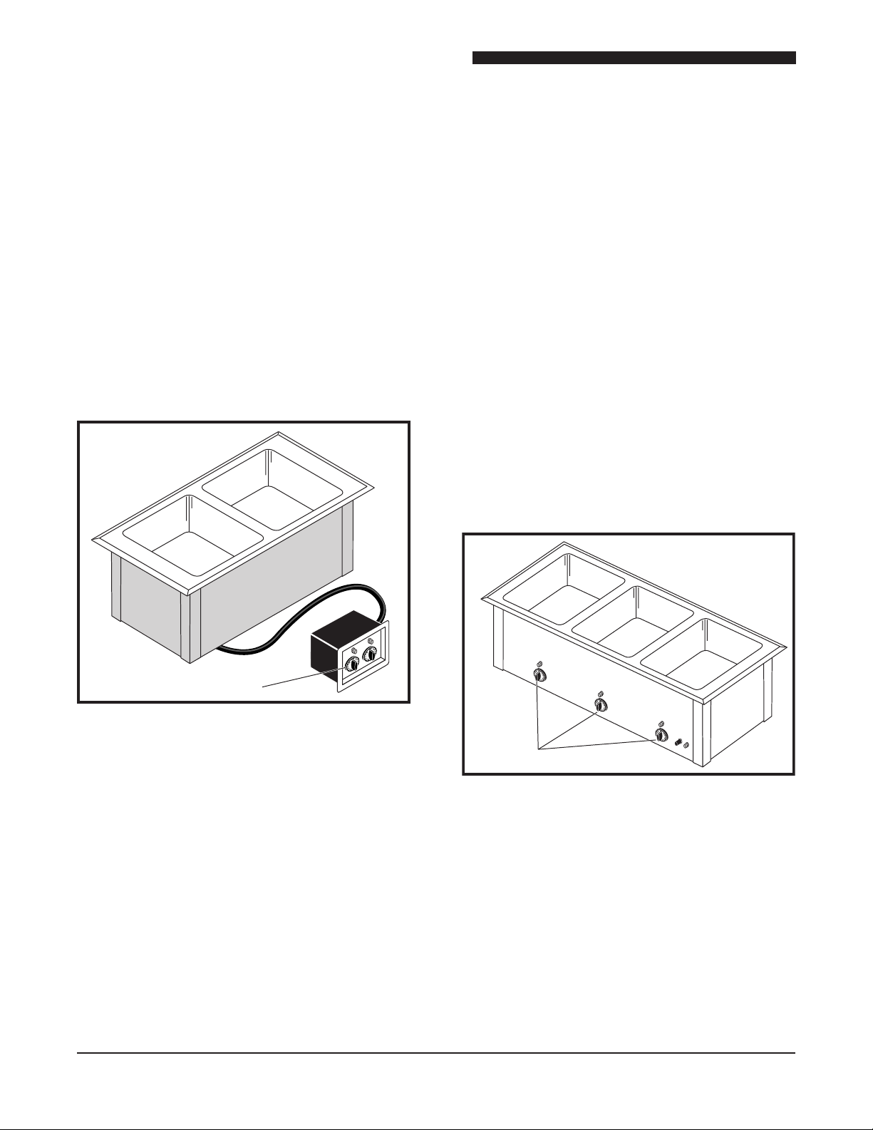
Figure 4. Location of Innite Switch –
Innite switches are located in a separate control
panel that is mounted to the front of the cabinet.
Figure 4 depicts an uninstalled ADI unit with the
remote innite switch control panel.
1. Disconnect unit from power source.
2. Remove the screws that hold the unit and
its remote innite switch controller in the
cabinet.
3. Pull the remote innite switch controller out of
the cabinet for servicing.
4. Remove screws holding the back cover of the
remote innite switch control panel in place.
6
Aerohot Drop-in (ADI) models
Figure 5.
Location of Thermostat –
Aerohot
Slide-in (ASI) models
Thermostats are located in front on the control
panel below each pan. Figure 5 depicts the location
of the thermostat.
1. Disconnect the unit from its power source.
2. Slide the unit out of its cabinet.
3. Turn the unit upside down and remove the
screws that hold the bottom cover in place.
 Loading...