

Duke 613Q-G4 User Manual
153810Q
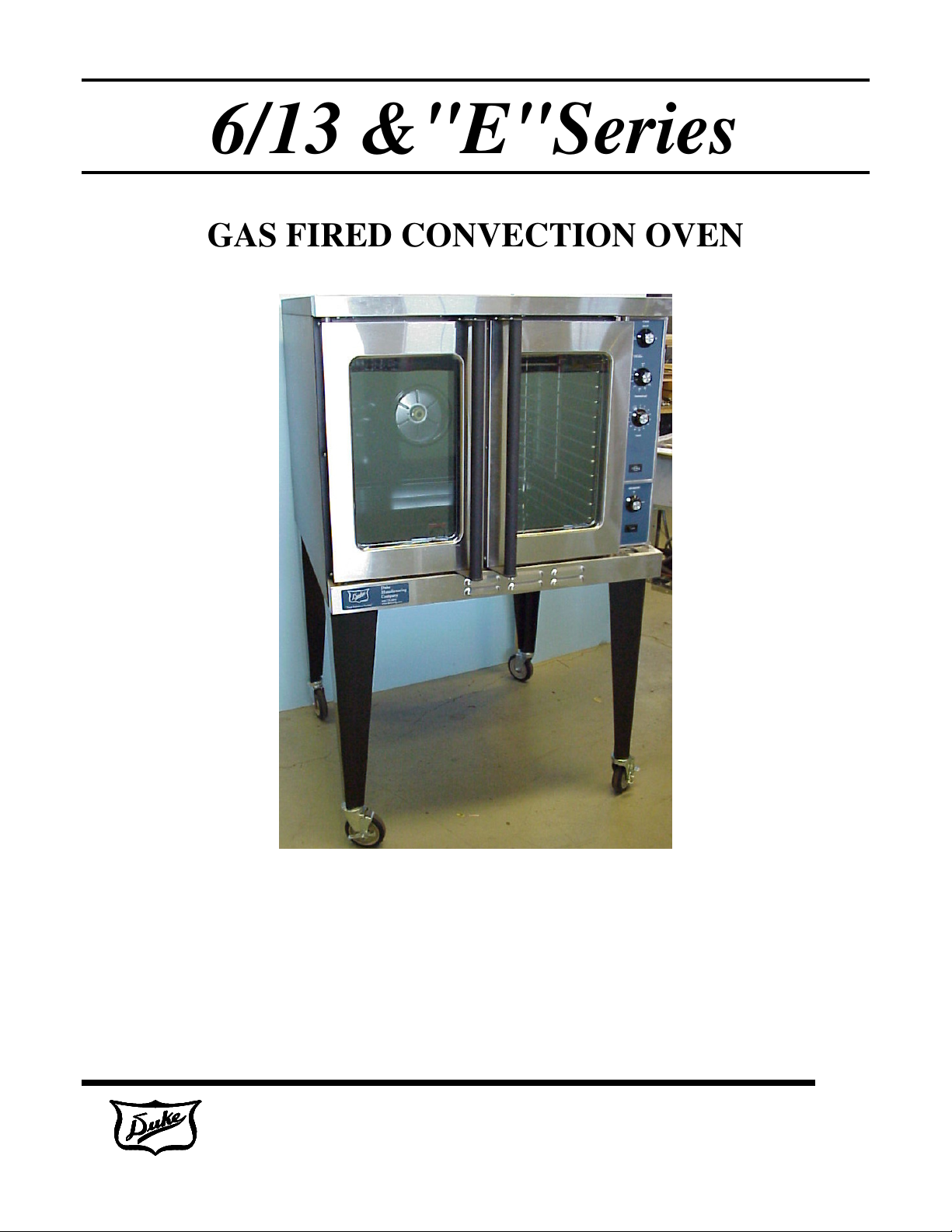
6/13 &"E"Series
GAS FIRED CONVECTION OVEN
Installation, Operation, Parts
& Maintenance Manual
Duke Manufacturing Co.
2305 N. Broadway • St. Louis, Missouri
800-735-3853 • 314-231-1130 • Fax 314-231-5074
www.dukemfg.com

6/13 & "E" Series Gas Specifications 3
Installation Instructions
A. Qualified Personnel
B. Delivery & Inspection 4
C. Location of Oven 4
D. Gas Piping 5
E. Electrical Connections 6
F Ventilation 6
G. Gas Oven Assembly 6-7
H. Adjustments Associated with Installation 7
I. Double Stack Ovens 8
Operating Instructions 9
A. Oven Controls
B. General Guidelines for Operation 13
C. Suggested Times & Temperatures 14
D. Cleaning the Oven 15
INDEX
PAGE
4
10 - 12
Maintenance Instructions
A. Adjustments 16
B. Door Adjustment 15
C. Door Switch Adjustment 15 - 16
D. Thermostat Calibration 16
E. Gas Pressure Regulation & Adjustment 17
F. Venting System 17
Repair Parts List 18
Door Assembly 19
“V” Controller Assembly 20
“XX Controller Assembly 21
Wiring Diagram 22
Please supply the ID Number and the Serial Number when ordering replacement parts or
requesting service. We recommend service by Duke Authorized Service Agencies during and
after the warranty period.
Duke Manufacturing Co.
2305 N. Broadway • St. Louis, Missouri
800-735-3853 • 314-231-1130 • Fax 314-231-5074
www.dukemfg.com
2 of 22
GAS PRESSURE AT
OVEN INPUT STANDARD DEPTH
BURNER ORIFICE SIZE
Instructions to be followed in the event the user smells gas. This information shall
POST IN A PROMINENT LOCATION:
be obtained by consulting the local gas supplier.
Specifications
HEATING VALUE
SPECIFIC GRAVITY
FOR YOUR SAFETY:
Do not store or use gasoline or other flammable vapors or liquids in the vicinity of
this or any other appliance.
WARNING:
Improper installation, adjustment, alteration, service or maintenance can cause
property damage, injury or death. Read the installation, operating and maintenance
instructions thoroughly before installing or servicing this equipment.
“E” & 6/13 SERIES GAS CONVECTION OVEN
NATURAL GAS
1000 BTU
0.63
37.3 MJ/m3
0.63
PROPANE GAS
2550 BTU
1.53
95.0 MJ/m3
1.53
MANIFOLD
PER BURNER
PER OVEN
3.5" W.C 0.87 kPa 10" W.C. 2.49 kPa
20,000 BTU/HR
40,000 BTU/HR
OVEN INPUT DEEP DEPTH
PER BURNER
PER OVEN
STANDARD DEPTH
DEEP DEPTH
23,000 BTU/HR
46,000 BTU/HR
#44
#43 2.26mm #54 1.40mm
Duke Manufacturing Co.
2305 N. Broadway • St. Louis, Missouri
800-735-3853 • 314-231-1130 • Fax 314-231-5074
5.9 kW
11.8 kW
6.8 kW
13.5 kW
2.18mm
www.dukemfg.com
20,000 BTU/HR
40,000 BTU/HR
23,000 BTU/HR
46,000 BTU/HR
#55
5.9 kW
11.8 kW
6.8 kW
13.5 kW
1.32mm
3 of 22

must be maintained between the oven and any
INSTALLATION INSTRUCTIONS:
A. Qualified Personnel
These installation instructions are for the use of qualified
installation and service personnel only. Installation or
service by other than qualified personnel may result in
damage to the oven and/or injury to the operator.
Qualified installation personnel are those individuals,
firms, companies or corporations which either in person
or through an agent is engaged in and responsible for:
• The installation or replacement of gas piping or the
connection, installation, repair or servicing of
equipment, who are experienced in such work,
familiar with all precautions required, and have
complied with all requirements of state and local
authorities having jurisdiction. See: National Fuel
Gas Code NFPA 54 (ANSI Z223.1).
• The installation of electrical wiring from the electric
meter, main control box or service outlet to the
electrical appliance. Qualified installation personnel
must be familiar with all precautions required and
have complied with all requirements of state and
local authorities having jurisdiction. See: National
Electrical Code, ANSI/NFPA70.
The installation must conform with local codes, or in the
absence of local codes, with the National Fuel Gas Code,
ANSI Z223.1/NFPA 54, or the Natural Gas and Propane
Installation Code, CSA B149.1 as applicable, including:
•
The appliance and its individual shutoff valve must
be disconnected from the gas supply piping system
during any pressure testing of that system at test
pressures in excess of ½ psi (3.5 kPa).
•
The appliance must be isolated from the gas supply
piping system by closing its individual manual
shutoff valve during any pressure testing of the gas
supply piping system at test pressures equal to or
less than ½ psi (3.5 kPa).
For an oven equipped with casters, the installation shall
be made with a connector that complies with the Standard
for Connectors for Movable Gas Appliances, ANSI
Z21.69/CSA 6.16 and a quick-disconnect device that
complies with the Standard for Quick-Disconnect Devices
for Use with Gas Fuel, ANSI Z21.4/CSA 6.9. When
installing the oven with casters and quick-disconnect
hose, adequate means must be provided to limit the
movement of the oven without depending on the
connector and the quick disconnett device or its
associated piping to limit the oven movement. Restraining
means may be attached to the vertical portion of the base
frame in the rear of the oven.
B. Delivery and Inspection
Duke Manufacturing Co. does everything within its power
to insure you received your oven in good condition. They
are strapped down on heavy wooden skids and surrounded
by heavy "tri-wall" cartons to prevent shipping damage.
They have all been carefully inspected before they were
packaged and consigned to the carrier.
Upon delivery of your Duke oven:
• Look over the shipping container, carefully noting
any exterior damage on the delivery receipt, which
must also be signed by the driver/ delivery person.
• Uncrate and check for any damage, which was not
evident on the outside of the shipping container.
This is called concealed damage. The carrier must
be notified within fifteen (15) days of the delivery of
the oven and the carton, skid and all packaging
materials must be retained for inspection.
Duke Manufacturing Co. cannot assume liability for loss
or damage suffered in transit. The carrier assumes full
responsibility for delivery in good order when the
shipment was accepted. However, we are prepared to
assist you in filing your claim.
C. Location of the Oven
Proper planning and placement of the oven will give you
the best results in terms of long-term user convenience
and satisfactory performance. We urge you to give
adequate thought in the placement of your oven prior to
its arrival.
• The oven should be placed in an area that is free
from drafts and accessible for proper operation and
servicing.
• The area around the oven must be kept clear of
combustible materials. A minimum clearance of:
Combustible
RIGHT SIDE
LEFT SIDE
REAR
FLOOR
1" 0”
1" 0”
3" 3”
8" 8”
combustible or non-combustible surface.
NonCombustible
Duke Manufacturing Co.
2305 N. Broadway • St. Louis, Missouri
800-735-3853 • 314-231-1130 • Fax 314-231-5074
www.dukemfg.com
4 of 22
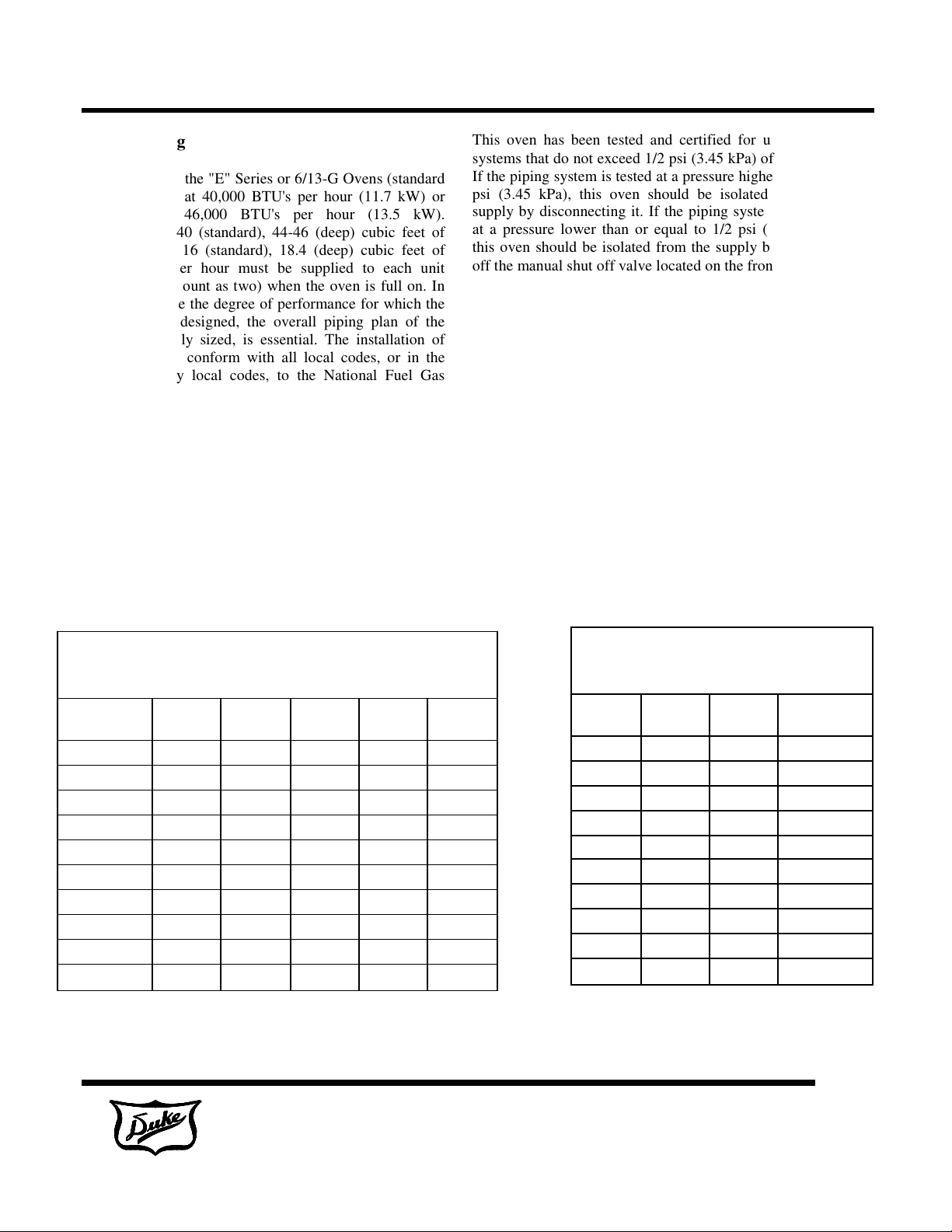
D. Gas Piping
Each section of the "E" Series or 6/13-G Ovens (standard
depth) is rated at 40,000 BTU's per hour (11.7 kW) or
(deep depth) 46,000 BTU's per hour (13.5 kW).
Therefore, 38-40 (standard), 44-46 (deep) cubic feet of
natural gas or 16 (standard), 18.4 (deep) cubic feet of
propane gas per hour must be supplied to each unit
(stacked units count as two) when the oven is full on. In
order to achieve the degree of performance for which the
unit has been designed, the overall piping plan of the
kitchen, properly sized, is essential. The installation of
this oven must conform with all local codes, or in the
absence of any local codes, to the National Fuel Gas
Code, NFPA 54 and ANSI Z 223.1.
Your local gas supplier should consult the National Fuel
Gas Code for proper sizing and installation of gas piping.
Generally, piping should be sized to provide a gas supply
sufficient to meet the maximum demand of all gas
appliances on a line without undue loss of pressure at the
outlet to the equipment. The total BTU requirements of
the equipment being served and the length of the piping
from the meter to the appliances are major considerations
in the proper design of the gas supply system.
This oven has been tested and certified for use on gas
systems that do not exceed 1/2 psi (3.45 kPa) of pressure.
If the piping system is tested at a pressure higher than 1/2
psi (3.45 kPa), this oven should be isolated from the
supply by disconnecting it. If the piping system is tested
at a pressure lower than or equal to 1/2 psi (3.45 kPa),
this oven should be isolated from the supply by shutting
off the manual shut off valve located on the front panel.
MAXIMUM CAPACITY OF IRON PIPE IN CUBIC FEET PER
HOUR (PRESSURE DROP OF 0.5" W.C.) NATURAL GAS
Length in Feet
10
20
30
40
50
60
70
80
90
100
1/2"
175
120
97
82
73
66
61
57
53
50
From National Fuel Gas Code
3/4"
360
250
200
170
151
138
125
118
110
103
1"
680
465
375
320
285
260
240
220
205
195
1.1/2"
2100
1460
1180
990
900
810
750
690
650
620
2"
3950
2750
2200
900
1680
1520
1400
1300
1220
1150
MAXIMUM CAPACITY OF PIPE IN
THOUSANDS OF BTU'S PER HOUR OF
UNDILUTED PROPANE GAS AT 11" W.C.
Length
in Feet
10
20
30
40
50
60
70
80
90
100
1/2"
275
189
152
129
114
103
96
86
83
78
From National Fuel Gas Code
3/4"
567
393
315
267
237
217
196
185
173
162
1"
1071
732
590
504
448
409
378
346
322
307
Duke Manufacturing Co.
2305 N. Broadway • St. Louis, Missouri
800-735-3853 • 314-231-1130 • Fax 314-231-5074
www.dukemfg.com
5 of 22
prong
(grounding) plug for your protection against shock
hazard and should be plugged directly into a properly
prong receptacle. DO NOT cut or
Keep the oven are
a free and clear from combustibles.
E. Electrical Connections
Your oven is supplied for connection to a 115 volt, single
phase grounded circuit. The electric motor, oven lights,
indicator lights and control circuits are connected through a
seven-foot electric supply cord found at the rear of the
oven.
Before making any connections to these units, check the
rating plate to assure that the voltage and phase of the oven
is compatible with the electrical supply. When installing,
all ovens must be electrically grounded in accordance with
local codes, or in the absence of local codes, with the
National Electrical Code, ANSI/NFPA 70 (in Canada -
CSA Std. C22.2). Wiring diagrams are located in the
control compartment area of the oven. Standard wiring
schematics are also provided with this manual.
WARNING:
This appliance is equipped with a three-
grounded threeotherwise remove the grounding prong from this plug.
F. Ventilation
Proper ventilation is very important for the proper function
of your oven. A good ventilation system will allow the
oven to function properly as well as remove unwanted
vapors and products of combustion. Not venting the ovens
properly can result in unsatisfactory baking results as well
as the possibility of damaging your oven. To keep your
warranty in force, a proper ventilation system must be
employed, either direct vented or under a canopy.
Venting to a Canopy Exhaust Hood
The best way to vent your oven is by placing it under a
properly designed mechanically driven exhaust hood. The
hood should be sized so the equipment that it is designed to
ventilate fits underneath with a minimum six (6) inch (152
mm) overhang on all sides not adjacent to a wall. The
distance from the floor to the lower edge of the canopy
should not exceed seven (7) feet (2.2 m).
The hood should have adequate capacity and provide a
sufficient supply of make- up air. Ventilation hoods come
in many sizes and capacities. Hood capacity is expressed in
cubic feet per minute (CFM). The total make-up and
exhaust air required for the canopy hood should be about
22 CFM per oven section. Information for the proper
construction and installation of ventilating hoods may be
obtained from the "Standard for the Installation of
Equipment for the Removal of Smoke and Grease-Laden
Vapors from Commercial Cooking Equipment, NFPA-96".
Direct Flue Venting
Occasionally it is not possible or practical to install a
powered canopy hood. In those cases the oven can be
vented directly by means of a direct flue method. Correctly
venting your oven is very important to insure proper
cooking results and preclude any premature failures in the
burner or burner compartment. The direct flue method
incorporates a drafthood that is mounted to the top of the
oven (or the upper oven section in a stacked unit). The flue
then rises from the drafthood vertically to a point 6-8 feet
above the roof or any close structure. The flue is then
capped with an approved vent cap to isolate the flue from
the external environmental conditions.
The direct flue method does not incorporate the ability to
replace air consumed by and vented from the oven. An
adequate supply of room make-up air must be provided if
your oven is to be vented by this method. The total
makeup air requirement for one oven section is
approximately 30 CFM.
Lighting Instructions:
• Turn Gas Shut Off to ON Position
• Turn Power Switch to COOK Position
• Set Thermostat to Desired Temperature
Shut Down Instructions:
• Turn Power Switch to OFF Position
• Wait 5 Minutes Before Relighting Oven
WARNING:
Note: This manual must be retained for future
reference.
G. Oven Assembly
Before assembling and installing the oven, please check to
make sure that all necessary parts are present. In addition
to the oven itself, there will also be legs, feet or casters, the
flue/vent guard or drafthood & drafthood collar assembly,
(for double sections, retaining clips, flue riser and/or
common manifold) and miscellaneous hardware. Please
check the interior of all oven sections for the parts needed
to assemble and install your oven(s).
Leg Attachment
• Once the oven has been removed from the carton, lay
it on its left side (the side without the controls), hold
the leg and align with the threaded holes in the front
comer of the bottom of the oven. Carefully start the
threads of the comer leg bolt (5/16"-18 X 1/2"),
2305 N. Broadway • St. Louis, Missouri
800-735-3853 • 314-231-1130 • Fax 314-231-5074
Duke Manufacturing Co.
www.dukemfg.com
6 of 22
avoid cross threading.
• Align the leg plate holes in each leg with those in the
corners of the oven bottom and secure using two 5/
16"-18 x 1/2" bolts. Tighten all bolts firmly. Repeat
this procedure for all legs.
• Raise the oven up on its legs.
Level the oven by turning the adjustable feet in or out as
needed.
Caster Installation
• Casters are available as an option for both the single
and double oven sections.
• The installation of casters requires the removal of
the adjustable feet from the legs. This is done by
placing the bit of a large screwdriver against the lip
of the foot and rapping the screwdriver to drive the
foot out of the leg. The caster is then inserted fully
into the opening where the foot came out and the
locking nut tightened to expand the compression
sleeve of the caster.
NOTE: The casters with locking brakes are best
mounted on the front side of the oven for easier access.
NOTE: If you plan to use casters and flexible fuel gas
connectors, a fixed restraint of the proper length must
be incorporated to secure the oven to a non-movable
surface to eliminate strain on the connector. If the oven
is removed from its normal position, the restraint must
then be reattached when returned.
Installation of the Vent
• Ovens ordered for installation under a powered
canopy exhaust hood should have the flue guard in
place. This item can be installed by placing it over
the flue opening, making sure that it does not
obstruct the flue, and attaching it with the screws
provided.
• Ovens ordered for installation in a location other than
under a powered canopy exhaust hood are supplied
with a drafthood & drafthood collar. This device
mounts to the top of the upper oven section by
attaching the drafthood adapter to the flue opening
with the screws provided, the drafthood is then
mounted on top of the adapter. The flue pipe is
attached vertically to the drafthood.
H. Adjustments Associated with Installation
Each oven section and all its component parts have been
tested thoroughly and inspected before your oven was
shipped from the factory. However, it is sometimes
necessary to further test or adjust the oven once it has been
installed. Such adjustments are the responsibility of the
Dealer or Installer. These types of adjustments are not
considered defects, rather a normal and routine part of the
proper installation of the equipment.
These adjustments include but are not limited to:
• Adjustments and recalibration of the thermostat
• Adjustment to the doors.
• Burner or pilot adjustment.
• Adjustments to the gas pressure regulator.
• Leveling, and tightening of fasteners.
No installation should be considered complete without
proper inspection and, if necessary, any adjustments by
qualified service or installation personnel.
It is also important not to obstruct the natural flow of
combustion and ventilation air if the oven is to operate
properly. This oven should not be installed on a curb base
or sealed to the wall. Either condition can restrict the flow
of air to the combustion compartment or prevent proper
ventilation of the blower motor. The blower motor has a
thermal protection device that will trip because of
excessive ambient temperature at the back of the oven.
This condition should be corrected immediately to avoid
damaging the oven permanently.
Before making any connections to the oven, check the
ratings plate to be sure the oven specifications concur with
the type of gas and voltage to be supplied to the oven.
The rating plate is located behind the lowered lower front
panel. To access, loosen the four screws below the doors,
and pull panel outward.
The plate bearing the oven's serial number is attached to
the underside of the upper ledge above the control panel.
I. Double Sections
• Secure the short legs to the bottom of the lower
section as described in previous section.
• Casters are installed by the method described for
single section ovens. Previous section.
• Place upper section on top of lower section and align
all edges of the ovens.
• Locate securing clips and align with holes on rear
frames of oven section, install three screws each as
provided and tighten.
• At the rear of the oven, install the flue connector by
sliding it up through the flue vent opening in the top
of the oven and over the upper flue vent. Push it
flush with the back of the oven then slide it down
over the lower flue vent. Attach with screws
provided.
• Install flue guard or drafthood adapter, drafthood and
drafthood collar to upper section.
See drawing on next page.
Duke Manufacturing Co.
2305 N. Broadway • St. Louis, Missouri
800-735-3853 • 314-231-1130 • Fax 314-231-5074
www.dukemfg.com
7 of 22
 Loading...