

Page 1

NORTH
AMERICAN
DRÄGER
RETURN TO CD-ROM TABLE OF CONTENTS
OPERATOR’SINSTRUCTIONMANUAL
NARKOMED 3
ANESTHESIA SYSTEM
Page 2

RETURN TO CD-ROM TABLE OF CONTENTS
Page 3

RETURN TO CD-ROM TABLE OF CONTENTS
NARKOMED 3
OPERATOR’S INSTRUCTION MANUAL
TABLE OF CONTENTS
FOREWORD ....................................................i
GENERAL DESCRIPTION ......................................... 1
MOVING THE NARKOMED 3 ....................................... 3
GAS DELIVERY SYSTEM .......................................... 4
AV-E ANESTHESIA VENTILATOR .................................. 20
POWER SUPPLY SYSTEM ........................................ 23
MAIN SWITCH PANEL ........................................... 26
MONITORING SYSTEM .......................................... 28
NARKOMED 3 SETUP & INSTALLATION ............................. 53
PRE-USE CHECKOUT PROCEDURE ................................ 62
CLEANING AND STERILIZATION ................................... 69
PRECAUTIONS (MAINTENANCE & USE) ............................. 71
SPARE AND REPLACEMENT PARTS ................................ 74
APPENDIX 1: NARKOMED 3 SPECIFICATIONS ........................ 76
APPENDIX 2: NARKOMED 3 ALARM MESSAGES ....................... 84
APPENDIX 3: NARKOMED 3 TROUBLESHOOTING GUIDE ................ 90
APPENDIX 4: VISUAL SYMBOLS ................................... 91
INDEX ....................................................... 92
Page 4

RETURN TO CD-ROM TABLE OF CONTENTS
Page 5

RETURN TO CD-ROM TABLE OF CONTENTS
FOREWORD
OPERATOR’S RESPONSIBILITY FOR PATIENT SAFETY
North American Dräger anesthesia products
are designed to provide the greatest degree of
patient safety that is practically and
technologically feasible. The design of the
equipment, the accompanying literature, and
the labeling on the equipment take into
consideration that the purchase and use of
the equipment are restricted to trained
professionals, and that certain inherent
characteristics of the equipment are known to
the trained operator. Instructions, warnings,
and caution statements are limited, therefore,
to the specifics of the North American Dräger
design.Thispublicationexcludes references to
hazards which are obvious to a medical
professional, to the consequences of product
misuse, and to potentially adverse effects in
patients with abnormal conditions. Product
modification or misuse can be dangerous.
North American Dräger disclaims all liability
for the consequences of product alterations or
modifications, as well as for the consequences
which might result from the combination of
North American Dräger products with
products supplied by other manufacturers if
such a combination is not endorsed by North
American Dräger.
The operator of the anesthesia system must
recognize that the means of monitoring and
discovering hazardous conditions are specific
to the composition of the system and the
various components of the system. It is the
operator, and not the various manufacturers
or suppliers of components, who has control
overthe final compositionand arrangement of
the anesthesia system used in the operating
room. Therefore, the responsibility for
choosing the appropriate safety monitoring
devices rests with the operator and user of
the equipment.
Patient safety may be achieved through a
variety of different means depending on the
institutional procedures, the preference of the
operator, and the application of the system.
These means range from electronic
surveillance of equipment performance and
patient condition to simple, direct contact
between operator and patient (direct observation of clinical signs). The responsibility for
the selection of the best level of patient
monitoring belongs solely to the equipment
operator. To this extent, the manufacturer,
North American Dräger, disclaims responsibility for the adequacy of the monitoring
package selected for use with the anesthesia
system. However, North American Dräger is
available for consultation to discuss
monitoring options for different applications.
NorthAmericanDräger’s liability, whether
arisingoutoforrelatedto manufacture and
sale of the goods, their installation,
demonstration, sales representation, use,
performance, or otherwise, including any
liability based upon North American
Dräger’s Product Warranty, is subject to
and limited to the exclusive terms and
conditionsas set forth,whether based upon
breach of warranty or any other cause of
action whatsoever, regardless of any fault
attributabletoNorth American Dräger and
regardless of the form of action (including,
without limitation, breach of warranty,
negligence, strict liability, or otherwise).
LIMITATION OF LIABILITY
THESTATED EXPRESSED WARRANTIES ARE
IN LIEU OF ALL OTHER WARRANTIES, EXPRESSEDORIMPLIED,INCLUDING,WITHOUT
LIMITATION, WARRANTIES OF MERCHANTABILITY, FITNESS FOR ANY PARTICULAR
PURPOSE, OR NON-INFRINGEMENT.
North American Dräger shall not be liable
for, nor shall buyer be entitled to recover
any special incidental, or consequential
damages or for any liability incurred by
buyer to any third party in anyway arising
out of or relating to the goods. North
American Dräger disclaims any liability
arising from a degraded system due to an
improperly designed or malfunctioning
third party interfaced product.
i
Page 6

WARRANTY
RETURN TO CD-ROM TABLE OF CONTENTS
All North American Dräger products are
guaranteed to be free of defects of
workmanshipormaterialforaperiodofone
year from date of delivery. The following
are exceptions to this warranty:
1. Defects caused by misuse,
mishandling, tampering, or by
modifications not authorized by
North American Dräger or its
representatives are not covered.
2. Rubber and plastic components and
materialsarewarrantedtobefreeof
defects at time of delivery.
3. Respiratoryvolumesensors, fuel-cell
oxygen sensors, and the MINUTE
VOLUMETER have a six-month
limited warranty. Fuel-cell oxygen
sensor capsules have an
eight-month limited warranty from
the date of delivery.
®
4. Warranty for Durasensors
is
limited to a period of six months
from the date of delivery.
Oxisensors
™
are warranted to be
free of defects at time of delivery.
Any product whichproves tobe defectivein
workmanship or material will be replaced,
credited, or repaired with North American
Drägerholding the option.North American
Dräger is not responsible for deterioration,
wear, or abuse. In any case, North
American Dräger will not be liable beyond
the original selling price.
Goodsare subjectto the termsof applicable
warranty. Defective products will be
accepted for return at North American
Dräger’s discretion, and only during the
warranty period.
Application of this warranty is subject to
the following conditions:
1. North American Dräger or its
authorized representative must be
promptly notified, in writing, upon
detectionof thedefectivematerialor
equipment.
2. Defective material or equipment
mustbe returned, shippingprepaid,
to North American Dräger or its
authorized representative.
3. Examination by North American
Dräger or its authorized representative must confirm that the defect
is covered by the terms of this
warranty.
4. Notification in writing, of defective
material or equipment must be
received by North American Dräger
or its authorized representative no
later than two (2) weeks following
expiration of this warranty.
In order to assure complete protection
under this warranty, the
Warranty-Registrationcardand/orPeriodic
Manufacturer’s Service record (if
applicable) must be returned to North
American Dräger within ten (10) days of
receipt of the equipment.
The above is the sole warranty provided by
NorthAmerican Dräger.Nootherwarranty
expressed or implied is intended.
Representatives of NorthAmerican Dräger
are not authorized to modify the terms of
this warranty.
DURASENSOR and OXISENSOR are Trademarks of Nellcor Incorporated.
ii
Page 7

RETURN TO CD-ROM TABLE OF CONTENTS
TERMS AND CONDITIONS
All merchandise to be returned must have
prior written authorization by North
American Dräger, and a valid Return
Material Authorization (RMA) Number
shall appearon the shipping label, packing
slip, purchase order and any other related
documents.
When requesting authorization to return
material, the following information should
be provided:
1. Customer purchase order and date.
2. NAD order number, shipping date,
and method of shipment (available
from packing slip).
3. Invoice date and number.
4. Quantity,NADproduct number, and
description of merchandise to be
returned.
5. Reason for return.
The following are accepted reasons for
return of merchandise:
1. Materialfailurewithinthewarranty
period.
2. Repairs.
3. Customer order in error.
4. Sales/Service order entry error.
5. Shipping Errors.
Material is subject to the terms of any
applicable warranty. Premature failure of
products shall be accepted for return at
North American Dräger’s discretion, and
only during the warranty period.
Material to be returned which is not under
warranty should have been purchased
withinthirtydaysofrequestforreturn,and
returned within thirty days after request.
Material shall be returned unused, and in
NADshippingcontainers.Materialshallbe
subjecttoa20%restockingcharge,withthe
exception of material failure within the
warranty period or NAD error.
The following merchandise is not eligible
for return, unless proven defective:
1. Sterile material, unless shipped in
error by NAD.
2. Rubberandplastic components that
have been used.
3. Speciallyordered orproduceditems.
5. Material which has been altered or
abused.
All items to be returned should be shipped
to:
North American Dräger
Technical Service Department
24 Commerce Drive
Telford, PA 18969
Attn: Customer Service Department
(Include RMA Number)
Any shortages or errors in shipment of
goods must be reported to North American
Dräger within two (2) weeks of receipt.
iii
Page 8

REPAIR AND SERVICE
RETURN TO CD-ROM TABLE OF CONTENTS
Repair of this equipment must be
performed by an authorized North
American Dräger Technical Service
North American Dräger recommends that
anesthesia machines be serviced at three
month intervals.
Representative.
Periodic Manufacturer’s Service Contracts
North American Dräger products/material
in need of factory repair shall be sent to:
areavailable forproducts manufactured by
NorthAmericanDräger.These agreements
are available from the NAD Inc. Technical
North American Dräger
Technical Service Department
Service Department or our Factory
Authorized Technical Service Centers.
24 Commerce Drive
Telford, PA 18969
(Include RMA Number)
RESTRICTION
Federal law restricts this device to sale by, or on the order of, a physician.
iv
Page 9

DISPLAY SCREENS
SENSOR/CORD
LINE WRAPS
PATIENT
INTERFACE
PANEL
MANUAL
SPHYGMOMANOMETER
GAUGE (OPTIONAL)
VENTILATOR
BELLOWS
BREATHING SYSTEM
SENSOR INTERFACE
PANEL
MAIN SWITCH
PANEL
BOOM ARM
(OPTIONAL)
SYSTEM CONTROL
KEYPAD
MONITOR
RACK
AV-E VENTILATOR
THREE-GAS OR
FOUR-GAS SELECTOR
SWITCH (OPTIONAL)
FLOWMETER
BANK
VAPORIZERS
(OPTIONAL)
FRESHGAS
COMMON
OUTLET
O
2
FLUSH
BUTTON
OP30001
AUXILIARY OXYGEN
FLOWMETER (OPTIONAL)
RETURN TO CD-ROM TABLE OF CONTENTS
GENERAL DESCRIPTION
The NARKOMED
anesthesia system. All NARKOMED 3
machines are equipped with pneumatic
circuitry, for mixing gases and liquid
agent vapor, and a comprehensive
monitoring system.
The pneumatic system is capable of
delivering up to four gases simultaneously
and one liquid anesthetic agent from a
selection of up to three. Oxygen (O
nitrous oxide (N
NARKOMED 3 machines. Optional gases
are air, carbon dioxide (CO
Helium (O
-He).
2
®
3 is a continuous flow
) and
O) are standard on all
2
), and Oxygen-
2
2
Up to three optional vaporizers may be
mounted on the vaporizer exclusion
system. The optional vaporizers are
Halothane, Enflurane and Isoflurane.
The vaporizers are mechanically
interlocked so that only one vaporizer may
be used at a time.
The anesthesia machine’s monitoring
system integrates the functions of the
electronic monitors and organizes
information from these monitors on two
screens.
Figure 1 NARKOMED 3 Anesthesia System, Front View
1
Page 10

GENERAL DESCRIPTION (continued)
RETURN TO CD-ROM TABLE OF CONTENTS
The monitoring package includes an
oxygen analyzer, breathing pressure
monitor, respiratory volume monitor,
respiratory gas analyzer, pulse oximeter,
andnoninvasiveblood pressure monitor.In
addition, the anesthesia machine monitors
all key anesthesia system functions (e.g.,
oxygen supply pressure, O
O flow ratio,
2/N2
backup battery status).
The monitoring system organizes alarm
messages into Warnings, Cautions, and
Advisories, presenting them on the central
alarm display.
Audible alarms are organized into three
distinct sound patterns and are delivered
by a central audio annunciator. A second
display screen can present real-time trace,
trend, bargraph and data displays.
The NARKOMED 3 can be optionally
equipped with an absorber system and/or
a Bain circuit adapter. Two different
scavenger systems are available,
permitting the best match with the
hospital’s waste gas disposal system. An
adjustable Positive End Expiratory
Pressure (PEEP) valve is available on the
ventilator or absorber assembly.
FIVE PORT
SERIAL INTERFACE
(OPTIONAL)
PIPELINE
SUPPLY
FITTINGS
CIRCUIT
BREAKERS
OP30002
Figure 2 NARKOMED 3 Anesthesia System, Back View
AC CONVENIENCE
RECEPTACLES
(117 VAC OPTION)
VACUUM FITTINGS
FOR SUCTION
ASSEMBLY
(OPTIONAL)
AC POWER
CABLE
2
Page 11

HANDLE
PUSH/PULL BAR
(FRAME MOUNT)
(OPTIONAL)
PUSH/PULL BAR
(VENTILATOR MOUNT)
(OPTIONAL)
OP30003
RETURN TO CD-ROM TABLE OF CONTENTS
MOVING THE NARKOMED 3
When movingthe NARKOMED 3, use only
the handles shown in Figure 3. DO NOT
push or pull the anesthesia machine using
the Absorber System, Vaporizers,
Ventilator Bellows, or Boom Arm.
Remove the Absorber System, along with
anyexternal monitors orequipment,before
moving the anesthesia machine.
Retract the boom arm, before moving the
anesthesia machine.
The NARKOMED 3 is equipped with two
locking casterson the front of the machine.
These castersmay be unlockedby stepping
on the lock mechanism on top of the caster.
DO NOT attempt to move the anesthesia
machine while the casters are locked.
Exercise caution when moving the
anesthesia machine on ramps, or over
thresholds.
It is recommended that two people be used
when moving the machine.
Figure 3 Acceptable Handles for Transportation
3
Page 12

GAS DELIVERY SYSTEM
RETURN TO CD-ROM TABLE OF CONTENTS
Standard Gases
The NARKOMED 3 is equipped with
pneumatic circuitry for the delivery of
oxygen (O
) and nitrous oxide (N2O). It
2
has at least one oxygen and one nitrous
oxide yoke for attachment of gas cylinders.
Optional Gases
In addition to oxygen and nitrous oxide,
the NARKOMED 3 may be equipped with
up to two additional gases. The additional
gases may be air, oxygen-helium (O
mixture (25% O
dioxide (CO
, 75% He) or carbon
2
). The additional gas is
2
-He)
2
supplied to the anesthesia system by
means of pin-indexed cylinders and yokes,
diameter-indexed safety system (DISS)
pipeline connections, or both (if so
selected).
Color Coding
Pipeline Connections
The DISS gas fittings for oxygen, nitrous
oxide, and an optional third gas arelocated
on the right side of the flowmeter housing.
The DISS fittings prevent improper
connection of supply hoses. The inlets
include check valves to prevent back flow
leakage into the atmosphere when supply
hoses are not connected, or into the
attached supply hoses when reserve
cylinders are in use.
Each pipeline connection is equipped with
a filter to prevent foreign material from
entering the internal gas piping of the
NARKOMED 3. Pipeline gases should be
supplied at 50-55 psi.
Each connection, valve, gauge, and
flowmeter is labeled andcolor coded for the
appropriate gas, as shown in the table
below.
COLOR CODE
GAS MARKING
U.S. CANADA (CSA)
Air AIR Yellow Black/White checkered
Carbon Dioxide CO
2
Gray Gray
Oxygen-Helium O2-He Green/Brown Diag. Stripes White/Brown Diag. Stripes
Nitrous Oxide N2O Blue Blue
Oxygen O
2
Green White
4
Page 13

Gas Cylinder Yokes
O2 YOKE
O
2
YOKE
(OPTIONAL)
N
2
O YOKE
(OPTIONAL)
N
2
O YOKE
AIR ,CO2,
OR O
2
-He YOKE
(OPTIONAL)
OP30004
RETURN TO CD-ROM TABLE OF CONTENTS
GAS DELIVERY SYSTEM (continued)
The NARKOMED 3 can be equipped with
a maximum of two oxygen and two nitrous
oxide cylinder hanger yokes (Figure 4). An
additional yoke for an optional third gas is
also available. The cylinder is the primary
supply for carbon dioxide and oxygenhelium.
To prevent a cylinder from being
improperly connected, the yokes are
labeled, color-coded, and keyed for gasspecific cylinders using the Pin Index
Safety System.
Figure 4 Gas Cylinder Yokes (Right, Rear View)
5
Page 14

GAS DELIVERY SYSTEM (continued)
RETURN TO CD-ROM TABLE OF CONTENTS
A sintered bronze filter within each yoke
prevents foreign material from entering
the internal gas piping of the NARKOMED
3. A check valve in each yoke prevents
back flow into the cylinder or leakage into
the atmosphere if the cylinder is not
mounted on the yoke.
When the machine is configured with two
yokes for the same gas, the check valve
prevents migration of gas from one
cylinder to another. If a cylinder is not
mounted to a yoke, the attached yoke plug
shouldbe placedbetween the yokehandle’s
threaded bolt and the yoke’s gas inlet.
When attaching acylinder, ensure onlyone
washer is installed between the cylinder
and the yoke gas inlet. The use of
multiple washers may compromise the Pin
Index Safety System. The integrity of both
index pins must be verified whenever a
new cylinder is installed. Cylinders
attached to the hanger yokes must contain
gasatthe recommended pressures outlined
in the table below.
RECOMMENDED RESERVE CYLINDER
MAXIMUM PRESSURES
GAS MAX PSI
Pressure Regulators
Each cylinder gas circuit incorporates a
pressure regulator that reduces the gas
pressure. These regulators are preset
below the commonly used hospital pipeline
pressure of 50-55 psi to ensure that gas
will be supplied from the pipeline and not
the cylinder if both sources of supply are
open. Pressure relief valves, integral to the
regulator, prevent excessive pressure in
case of regulator failure or excessive
pipeline pressure.
NOTE: Canadian machines are equipped
with an additional pipeline overpressure
relief valve that is set to open at 75 psi
(520 kPa).
Cylinder Pressure Gauges
Each cylinder gas circuit on the
NARKOMED 3 is provided with a cylinder
pressure gauge, located at the bottom of
the flowmeter panel on the front of the
machine (Figures 5, 6, & 7). Each gauge is
labeled and color-coded for its respective
gas.
When a cylinder’s valve is open, its
pressure gauge indicates the gas pressure
in the cylinder. The dial is marked with
concentric scales in psi and kPa.
Air 2200
Carbon Dioxide 830
Oxygen-Helium 2400
Nitrous Oxide 745
Oxygen 2200
6
Page 15

10
9
8
7
6
5
4
3
2
11
2
3
4
5
6
7
8
9
10 1000
900
800
700
600
500
400
300
200
100100
200
300
400
500
600
700
800
900
1000
N2O
O
2CYLINDERCYLINDER
PIPELINEPIPELINE
COLOR-CODED
GAS LABEL
OP10005
CYLINDER
PRESSURE
GAUGE, O
2
PIPELINE
PRESSURE
GAUGE, O
2
PRECISION FLOW
CONTROL KNOB, O2
FLOWMETER KNOB
GUARD
INDICATOR
FLOATS, O
2
COARSE FLOW TUBE
(l/min), O
2
FINE FLOW TUBE
(ml/min), O2
N
2O
O
2
RETURN TO CD-ROM TABLE OF CONTENTS
GAS DELIVERY SYSTEM (continued)
Figure 5 Standard Flowmeter Bank
7
Page 16

GAS DELIVERY SYSTEM (continued)
COARSE FLOW TUBE
(l/min), N
20
RETURN TO CD-ROM TABLE OF CONTENTS
1000
1000
10 1000
10
10
FINE FLOW TUBE
(ml/min), N2O
INDICATOR
FLOATS, N2O
FLOWMETER KNOB
GUARD
PRECISION FLOW
CONTROL VALVE, N
PIPELINE PRESSURE
GAUGE, N
O
2
2O
900
800
700
600
500
400
300
200
100
N2O
900
9
800
8
700
7
600
6
500
5
400
4
300
3
200
2
100
1
AIR
9
900
8
800
7
700
6
600
5
500
4
400
3
300
2
200
1
100
0
9
8
7
6
5
4
3
2
1
2
PIPELINEPIPELINEPIPELINE
CYLINDER PRESSURE
GAUGE, N
2O
OP10006
Figure 6 Three-Gas Flowmeter Bank (Air Option)
8
N2O
AIR
2
CYLINDERCYLINDERCYLINDER
0
Page 17

RETURN TO CD-ROM TABLE OF CONTENTS
GAS DELIVERY SYSTEM (continued)
10
1000 10
900
800
700
600
500
400
300
200
10
9
8
7
6
5
4
3
2
9
8
7
6
5
4
3
2
1.0
.8
.6
.4
.2
10
1000
9
8
7
6
5
4
3
2
900
800
700
600
500
400
300
200
O2-He
100
N
2OO2
1
AIR
PIPELINE PIPELINE PIPELINE
100
AIR
FINE FLOW TUBE
(ml/min), O
9
COARSE FLOW TUBE
2
(l/min), O2
8
7
6
INDICATOR
5
4
FLOATS, O
2
FLOWMETER KNOB
3
2
GUARD
PRECISION FLOW
1
CONTROL KNOB, O2
PIPELINE
PRESSURE
GAUGE, O2
2
CYLINDER CYLINDER CYLINDER
-HeN2O
O
2
O
OP10007
Figure 7 Four-Gas Flowmeter Bank (Air & Oxygen-Helium Option)
CYLINDER
PRESSURE
GAUGE, O2
9
Page 18

GAS DELIVERY SYSTEM (continued)
RETURN TO CD-ROM TABLE OF CONTENTS
For non-liquefied gases (O
, Air, O2-He) the
2
indicated pressure is proportional to the
gas content of the cylinder. For liquefied
gases (N
O, CO2) the gauge indicates the
2
vapor pressure of the liquefied gas in the
cylinder. This pressure remains constant
until all of the liquid in the cylinder has
vaporized. When the liquid has vaporized,
the cylinder pressure decreases
proportionally with further removal of gas
from the cylinder.
NOTE: If two reserve cylindersof the same
gas are open at the same time, the cylinder
pressure gauge will indicate the pressure
in the cylinder having the higher pressure.
Pipeline Pressure Gauges
Pipeline pressure gauges for oxygen and
nitrous oxide are standard (Figures 5, 6, &
7). If the anesthesia machine is equipped
with air, a pipeline pressure gauge for air
is also included.
These gauges are located directly below
their corresponding flowmeters and flow
control valves, and are labeled and colorcoded for theirrespective gases.Concentric
scales in psi and kPa indicate thedelivered
pipeline supply pressure. When the
machine is connected to a functioning
pipelinesupply,each gauge shouldindicate
50-55 psi. A deviation from within this
range indicates an improperly adjusted
pipeline gas supply system and may
adversely affect the operation of the
NARKOMED 3.
A fluctuating pipeline supply pressure, for
example, would cause a corresponding
fluctuation of the delivered flow of that
gas. An excessively low pipeline pressure
may activate the corresponding reserve
cylinder and deplete its contents (if the
reserve cylinder valve was left in the open
position).
Carbon dioxide and oxygen-heliummixture
supplies for NARKOMED 3 machines are
provided exclusively from cylinders. Thus,
these gases do not require pipeline
pressure gauges.
10
Page 19

RETURN TO CD-ROM TABLE OF CONTENTS
GAS DELIVERY SYSTEM (continued)
Oxygen Supply Pressure Failure
Protection Device (OFPD)
The oxygen failure protection device
(OFPD) is a pneumatically operated valve
located in the anesthesia machine’s
internal supply lines for all machine gas
circuits except oxygen. The OFPD valve is
controlled by the gas pressure in the
oxygensupply line. Properoxygenpressure
keeps the valve open. A failure or
reduction of pressure in the oxygen supply
line will proportionally reduce and
eventually shut off the supply of all other
gases.
When the OFPD is activated, the
flowmeters indicate a reduced gas flow,
proportional to the reduction of oxygen
supply pressure. When the oxygen supply
pressure (from either pipeline or reserve
cylinders) drops below approximately 37
psi, an "LO O
SUPPLY" alarm message
2
appears on the central alarm display. The
red "O
SUPPLY PRESSURE" indicator
2
light on the main switch panel lights, and
an intermittent audible alarm sounds.
Flow Control Valves
A needle valve is located below the fine
flowmeter tube for each specific gas. This
valve is used to adjust the flow of gas
(Figures 5, 6, & 7). Counterclockwise
rotation of the valve knob increases flow,
while clockwise rotation decreases flow.
A zero stop prevents damage to the flow
control valve seats. If necessary, an
authorized service representative of North
American Dräger can readjust the stop.
Each flow control knob is identified by its
color code and chemical symbol. Also, the
oxygen flow control valve is touch-coded
with a deeply fluted knob.
Unless the anesthesia machine has been
specifically modified to eliminate the
minimum oxygen flow feature (see
"Minimum Oxygen Flow"), the flow of
oxygen cannot be totally shut off. DO NOT
force the oxygen flow control knob over its
end stop in an effort to shut off the flow.
Forcing the knob could damage the valve
seat.
If only one source of oxygen supply
pressure (either reserve cylinders or
pipeline) fails, while the other maintains
proper supply pressure within the
machine’s oxygen supply lines, the OFPD
and "LO O
SUPPLY" alarm will not
2
activate.
11
Page 20

GAS DELIVERY SYSTEM (continued)
Flowmeters
RETURN TO CD-ROM TABLE OF CONTENTS
Flowmeters, located immediately above
their corresponding flow control valves
(Figures 5, 6 & 7), display the flow rate of
each gas delivered for the fresh gas
mixture. Dual (fine and coarse) flowmeter
tubes are used in tandem for oxygen,
nitrous oxide, and air (if provided). Single
flowmeter tubes are used for other gases
when supplied.
Oxygen, nitrous oxide and air flowmeters
are equipped with floats, half chromeplated and half colored red, to indicate free
movement through rotation. Single tube
flowmeters are equipped with stainless
steel or black glass floats. Regardless of
the float type, the position of the center of
the ball along the flowmeter scale should
be used as an indication of the flow rate.
All flowmeters are labeled and color-coded
Oxygen, nitrous oxide, and air flowmeters
at each end of the flowtube.
are certified to be within ±2.5% of full
scale at 20° C and 760 mm Hg. Single
flowtubes are certified to be within ±5% of
full scale. Flowmeter ranges and
accuracies are outlined in the table below.
FLOWTUBE RANGES & ACCURACIES
GAS TUBE RANGE (l/min) ACCURACY (%FS)
Oxygen Fine 0-1 ±2.5
Oxygen Coarse 0-10 ±2.5
Nitrous Oxide Fine 0-1 ±2.5
Nitrous Oxide Coarse 0-10 ±2.5
Air Fine 0-1 ±2.5
Air Course 0 -10 ±2.5
0-1 ± 50 cc of range
Air Dual Tapered
0-10 ±5
Oxygen-Helium Single 0-10 ±5
Carbon Dioxide Single 0- 1.0 ±5
12
Page 21

RETURN TO CD-ROM TABLE OF CONTENTS
GAS DELIVERY SYSTEM (continued)
Low-Flow Flowmeters (Optional)
For low-flow anesthesia, the NARKOMED
3 can be configured with low-flow, dualtube flowmeters for oxygen and nitrous
oxide. These flowmeters function in the
same manner as the standard dual-tube
flowmeters, but are calibrated to provide
greater resolution for low-flow anesthesia.
They are calibrated as shown in the table
below.
Auxiliary Oxygen Flowmeter (Optional)
For the delivery of a metered flow of pure
oxygen (such as for the delivery of oxygen
through a nasal cannula), an optional
auxiliary oxygen flowmeter can be
mounted on the left side of the flowmeter
bank. It is calibrated from 0 to 10 l/min at
an accuracy of ±5% of full scale. This
flowmeter can be used with the machine
turned off.
Minimum Oxygen Flow
The oxygen dispensing system incorporates
a calibrated bypass flow of 150 ±50 ml/min
(at 50 psi pipeline pressure), to ensure the
delivery of some oxygen even if the flow
control valve is fully closed.
If required for low-flow anesthesia, the
NARKOMED 3 can be optionally modified
to eliminate the minimum oxygen flow
feature. A label above the oxygen
flowmeter indicates that the anesthesia
machine has been modified to eliminate
minimum oxygen flow.
If air is an additional gas, when the gas
selector switch is set to the "ALL GASES"
position, the minimum oxygen flow is
automatically disabled.
NOTE: The flow control valve for the
auxiliary oxygen flowmeter does not
include a zero stop. Do not over tighten.
LOW-FLOW FLOWTUBE RANGES & ACCURACIES
GAS TUBE RANGE ACCURACY
Oxygen Fine 0 - 500 ml/min ±2.5% (FS)
Oxygen Coarse 0 - 10 l/min ±2.5% (> 1 l/min)
±15% Rate (< 1 l/min)
Nitrous Oxide Fine 0 - 500 ml/min ±2.5% (FS)
Nitrous Oxide Coarse 0 - 10 l/min ±2.5% (> 1 l/min)
±15% Rate (< 1 l/min)
13
Page 22

GAS DELIVERY SYSTEM (continued)
Oxygen Ratio Monitor/Controller (ORMC)
RETURN TO CD-ROM TABLE OF CONTENTS
The ORMC is a pneumatic O
2/N2
O
interlock system designed to maintain a
fresh gas oxygen concentration of at least
25 ±4 %. It permits independent control of
the oxygen and nitrous oxide flows, but by
proportionally limiting the nitrous oxide
flow, the ORMC prevents a flow ratio that
could result in a hypoxic fresh gasmixture.
The ORMC works by limiting the nitrous
oxide flow whenever the operator selects
oxygen and nitrous oxideflow control valve
settings that would otherwise result in a
hypoxic fresh gas mixture. For example, if
the operator opens the nitrous oxide flow
control valve excessively without making a
corresponding increase in the oxygen flow
control valve setting, the flow of nitrous
oxide will not increase, even though its
flow control valve setting has been greatly
increased. Similarly, if the operator
decreases the oxygen flow without also
decreasing the nitrous oxide flow, the
nitrous oxide flow will automatically drop
in proportion to the oxygen flow.
Due to rebreathing of previously exhaled
gas in a circle system, lower fresh gas
flows require a higher oxygen
concentration to maintain a sufficient
inspiratory oxygen concentration. For that
reason, the ORMC is designed to maintain
higher levels of oxygen in the fresh gas at
lower flow rates. Figure 8 illustrates the
ORMC’s response curve.
NOTE: At lower fresh gas flow rates, the
ORMC maintains fresh gas oxygen
concentrations well above 25% of the
combined oxygen and nitrous oxide flow.
The ORMC interlocks only the flows of
oxygen and nitrous oxide. Hypoxic fresh
gas concentrations are possible if an
additional gas other than air is used.
14
Page 23

Gas Selector Switch (Optional)
)
RETURN TO CD-ROM TABLE OF CONTENTS
GAS DELIVERY SYSTEM (continued)
Setting the gas selector switch to the "O
O" position permits oxygen and nitrous
N
2
&
2
oxide flows to the appropriate flowmeter
controls. This position also enables the
minimum oxygen flow.
100
90
80
70
60
The "ALL GASES" position of the gas
selector switch permits the additional
gases to flow to their respective flowmeter
controls, allowing a mixture of all gases.
However, setting the switch to the "ALL
GASES" position automatically disables
the minimum O
flow.
2
OP10008
50
CONCENT RA TION (%)
2
DELIVERABLE OXYGEN CONCENTRATIONS
40
30
FRESHGAS O
20
10
UNDELIVERABLE OXYGEN CONCENTRATIONS
0 24 68101214161820
FRESH GAS FL OW RA TE (L/min
Figure 8 ORMC Response
15
Page 24

GAS DELIVERY SYSTEM (continued)
HANDWHEEL
ADJUSTMENT
FILLER
VALVE
DRAIN
VALVE
SIGHT
GLASS
FILLER
FUNNEL
OP20051
Vaporizers (Optional)
RETURN TO CD-ROM TABLE OF CONTENTS
The NARKOMED 3 can be equipped with
up to three Vapor 19.1 vaporizers for the
administration of liquid anesthetics. The
vaporizers (Figures 9 & 10) are located to
the right of the flowmeters.
Vaporizers may be equipped with either an
open-funnel filler or a pin-indexed filler.
(Only pin-indexed fillers are permitted in
Canada).
A calibrated concentration of vaporized
anesthetic is produced by adjusting the
top-mounted handwheel of the selected
vaporizer to the desired concentration
indicated on the dial. Clockwise rotation
decreases the anestheticconcentration and
counterclockwise rotation increases the
concentration.
Figure 9 Vaporizers (with Standard Filler/Drain Mechanisms)
16
Page 25

RETURN TO CD-ROM TABLE OF CONTENTS
GAS DELIVERY SYSTEM (continued)
A cam and lever interlock system,
incorporated into the vaporizer bank,
prevents more than one vaporizer from
being activated and requires all unused
vaporizers to be locked in their zero
volume percent positions.
Detailed operating instructions for the
vaporizers are in a separate manual
supplied with the vaporizer.
HANDWHEEL
ADJUSTMENT
WARNING: Only one vaporizer can be
activated at a time. If the exclusion system
permits simultaneous activation of more
than one vaporizer, DO NOT use the
anesthesia machine. Contact anauthorized
NAD service representative for repairs.
OP20052
FILLER
VALVE
SIGHT
GLASS
FILLER
PORT
PORT
DRAIN
DRAIN
VALVE
WING
SCREWS
Figure 10 Vaporizers (with Optional Pin-Indexed Filler/Drain Mechanisms)
17
Page 26
GAS DELIVERY SYSTEM (continued)
TABLETOP
FRESH GAS
OUTLET
FRESH GAS
LOCKING BAR
(EXTENDED POSITION)
HANDLE
LUER-FITTING
FOR MANUAL
SPHYGMOMANOMETER
(OPTIONAL)
RELEASE TO
LOCK
FRESH GAS
HOSE
OP10011
O2 FLUSH CONTROL
RETURN TO CD-ROM TABLE OF CONTENTS
Oxygen Flush
A manually operated, self-closing, oxygen
flush valve (Figure 11) is located on the
left front corner of the machine’s frame. A
bezel is mounted around the push button
in order to prevent accidental engagement.
The valve, when actuated, delivers an
unmetered oxygen flow of approximately
55 l/min directly to the NARKOMED 3’s
fresh gas common outlet. The oxygen flush
may be used without the SYSTEM
POWER switch being in the "ON" position.
Fresh Gas Common Outlet
The fresh gas common outlet (Figure 11)
delivers the fresh gas mixture (consisting
of oxygen, nitrous oxide, optional gases,
and vapors of a liquid anesthetic) to the
patient breathing system. It is located to
the left of the oxygen flush button on the
front of the anesthesia machine.
The outlet’s 15 mm cylindrical female
fitting is designed to accept a 15 mm male
fitting on the absorber fresh gas hose. The
male fitting slides into a retaining slot in
the spring-loaded safety locking bar
(Figure 11) to prevent inadvertent
disconnection of the fresh gas hose.
The 15 mm male fitting on the fresh gas
hose is unique to North American Dräger
design and cannot be replaced by that of
any other manufacturer.
Fresh Gas Adapter (Optional)
The optional fresh gas adapter allows the
NARKOMED 3 to monitor the fresh gas
oxygen concentration when using a nonrebreathing circuit. The fresh gas adapter
is designed to fit securely into the fresh
gas common outlet of the anesthesia
machine. A detailed description and
operating instructions can be found in the
Fresh Gas Adapter Operator’s Instruction
Manual.
Figure 11 Oxygen Flush Control & Freshgas Common Outlet
18
Page 27

RETURN TO CD-ROM TABLE OF CONTENTS
GAS DELIVERY SYSTEM (continued)
Fresh Gas Common Outlet (Canada)
The fresh gas common outlet (Figure 12)
delivers the fresh gas mixture (consisting
of oxygen, nitrous oxide, optional gases,
and vapors of a liquid anesthetic) to the
patient breathing system. It is located to
the left of the oxygen flush button on the
front of the anesthesia machine. The outlet
incorporates a dual fitting that allows use
of either a 15 mm male fresh gas hose
fitting (such as supplied with North
American Dräger Absorbers and Bain
Circuit Adapters) or a 22 mm female
fitting with a load-bearing threaded mount
(such as for Magill circuits meant to be
threaded onto the fresh gas common
outlet).
When using the 15 mm male and female
fittings, make sure that the spring-loaded
locking bar fits over the male fresh gas
hose fitting, securing it in the female
fitting.
When using the Magill circuit fitting,
swing the spring-loaded locking bar to the
side to gain access to the threaded load
bearing fitting.
Suction System (Optional)
The NARKOMED3 can be configured with
internal vacuum piping for a suction
drainage assembly. A DISS vacuum fitting
on the rear of the machine connects, via a
hose, to a wall vacuum outlet. The suction
drainage assembly mounts on a DISS
fitting on the machine’s right front corner.
The suction drainage assembly consists of
a 700 cc clear glass bottle, vacuum on/off
valve, vacuum control knob, and vacuum
gauge. A ball float at the top of the bottle’s
inlet pipe automatically prevents overfill.
Consultthe operatinginstructions supplied
with this device before use.
TABLETOP
OP10012
FRESH GAS
HOSE
SPHYGMOMANOMETER
RELEASE TO
LOCK
O
Figure 12 Oxygen Flush Control & Freshgas Common Outlet for Canada
2
FLUSH CONTROL
LUER-FITTING
FOR MANUAL
(OPTIONAL)
HANDLE
FRESH GAS
LOCKING BAR
19
Page 28

AV-E ANESTHESIA VENTILATOR
FREQUENCY
CONTROL
I.E.
RATIO
CONTROL
FLOW
GAUGE
FLOW
CONTROL
VENTILATOR
POWER
SWITCH
TIDAL VOLUME
ADJUSTMENT
KNOB
SETTING POINTER
TIDAL VOLUME
VENTIL ATO R RE LI EF
VALVE (W /1 9M M
SCAVEN GE R
HOSE TE RM IN AL )
22MM BREATHING
HOSE T ERM INAL
OP30014
RETURN TO CD-ROM TABLE OF CONTENTS
The anesthesia ventilator (Figure 13) is
volume-preset and time-cycled. It has a
solid-state timer andindependent controls.
Thepneumatic powerto the ventilatormay
be supplied through the pipeline supply or,
if the pipeline supply either fails or is
disconnected, through cylinders. The
pressure of the supply gas must be
between 40 and 60 psi. The ventilator will
not function if thispressure drops below 32
psi.
The monitoring system’s breathing
pressure and expiratory flow waveform
displays can be used as an aid in adjusting
the ventilator. For further details, see the
MONITORING SYSTEM section of this
manual.
Figure 13 AV-E Ventilator
20
Page 29

RETURN TO CD-ROM TABLE OF CONTENTS
AV-E ANESTHESIA VENTILATOR (continued)
NOTE: The anesthesia ventilator is
designed for use with an NAD absorber
system, which incorporates a
Manual/Automatic selector valve. This
valve allows the operator to bring into the
breathing system either the breathing bag
and pop-off valve for manual ventilation,
or the ventilator bellows for automatic
ventilation. Breathing system hose
connections to this valve are described in
the SETUP & INSTALLATION section of
this manual.
Ventilator Power Switch
The ventilator power switch controls both
pneumatic and electrical power to the
ventilator. In the "OFF" position the
ventilatoris notoperable, and theAdvisory
message "VENT OFF" appears on the
anesthesia machine’s central alarm
display. Inthe "ON" position the ventilator
is activated and cycles according to the
settings of the other controls.
The ventilator power switch also
automatically enables the monitoring
system’s volume-related alarms and apnea
pressure alarm.
Smaller tidal volumes can be adjusted by
setting the pointer below the 200 ml
marking on the bellows chamber. Larger
tidal volumes can be selected by choosing
settings above the 1400 ml calibration. As
in any volume-presetanesthesia ventilator,
the actual tidal volume delivered to the
patient’s lungs may differ from the preset
volume at the bellows due to the
compliance of the breathing system and
fresh gas flow. To accurately set the tidal
volume, the operator should refer to tidal
and minute volume measurements.
The position of the tidal volume indicator
can be calibrated by an NAD authorized
service representative for a specific
combination of fresh gas flow and
equipment compliance.
Frequency Control
The respiratory frequency can be set
between 1 and 99 BPM (in 1 BPM
increments) using the two-digit thumb
wheel switch labeled "FREQUENCY"
(Figure 13). A setting of "00" will cause the
ventilator to remain in the expiratory
phase indefinitely.
Tidal Volume Adjustment
The tidal volume may be adjusted between
50 and 1500 ml. A self-locking knob,
located above the bellows assembly (Figure
13), adjusts a bellows stop within the
canister. To adjust the tidal volume,
depress the self-locking knob to allow
rotation. Set the tidal volume, as indicated
by the pointer on the bellows chamber
scale (marked 200 to 1400 ml), to the
desired set point.
Inspiratory/Expiratory (I:E) Phase Time
Ratio Control
The operator can vary the
inspiratory/expiratory phase time ratio in
calibrated steps from 1:1 through 1:4.5.
Calibrations are marked on the I:E
controller-indicator thumb wheel in 0.5
increments. The thumb-wheel is located to
the right of the frequency thumb wheel
and is labeled "I:E RATIO" (Figure 13).
21
Page 30

AV-E ANESTHESIA VENTILATOR (continued)
RETURN TO CD-ROM TABLE OF CONTENTS
Inspiratory Flow Control
The rotary knob marked "INSPIRATORY
FLOW" controls the flow rate of gas into
the bellows chamber, and the inspiratory
flow rate of gas into the patient’s lungs.
However, due to such variables as total
lung compliance, equipment compliance,
and airwayresistance, the inspiratory flow
control cannot be calibrated with
numerical values. Instead,the gaugeto the
left of the control knob is labeled with
three zones, "LOW," "MEDIUM," and
"HIGH" (Figure 13).
The flow setting is to be adjusted so that
the bellows is fully compressed at the end
of the inspiratory phase. In order to deliver
the desired, preset tidal volume, adjust the
inspiratory flow control so that the bellows
corrugations make contact with each other
but are not deformed at the end of the
inspiratory phase.
The inspiratory flow control can be used to
create an inspiratory plateau at the end of
the inspiratory cycle. It also affects the
peak inspiratory pressure that can be
developed within the patient breathing
system. Always check the pressure
indicatedby the breathingsystem pressure
gauge and waveform when adjusting the
inspiratory flow control.
Ventilator Relief Valve
During automatic ventilation, the
manual/automatic selector valve isolates
the absorber’s APL (adjustable pressure
limiting) valve from the breathing system.
To compensate for the continuous
introduction of fresh gasinto the breathing
system, the ventilator incorporates a relief
valve mounted behind the bellows
chamber.
The ventilator relief valve remains closed
until the end of expiration so that the
ascending bellows can expand upward and
refill. When the bellows is completely
filled, any excess gas in the system is
released by the ventilator relief valve to
the scavenging system. As in any
ascending bellows, the force needed to
overcome gravity acting on the bellows
causes a PEEP within the breathing
system, in this case approximately 2 cm
O.
H
2
Bellows PEEP Valve (Optional)
An optional ventilator PEEP valve mounts
beneaththebellows.(An optional absorbermounted PEEP valve is also available.)
The operator can set a PEEP of
approximately 2 to 15 cm H
O with the
2
PEEP valve control knob. Clockwise
rotation of the knob increases PEEP and
counterclockwiserotation decreases PEEP.
The breathing system pressure gauge and
the breathing pressure monitor indicate
the amount of PEEP at the end of
exhalation. For details, see the Bellows
PEEP Valve Instruction Manual.
22
Page 31

Power Supply
RETURN TO CD-ROM TABLE OF CONTENTS
POWER SUPPLY
The NARKOMED 3 is equipped with a
central power supply for the ventilator,
alarm system, and monitoring system. The
power of each monitor is individually
regulatedto prevent voltagefluctuationsin
one monitor from influencing the
performance of the other monitors.
The NARKOMED 3 must be plugged into
an AC outlet when in use.
Power Cord
A fifteen foot cord with a 3-prong hospital
grade plug is supplied with the
NARKOMED 3. The allowable input
voltage range is from 90 to 130 VAC at 50
or 60 Hz. Excess cable is to be stored on
the cord wrap at the rear of the
NARKOMED 3. When unplugging the
power cord be sure to pull the plug, not the
cord.
Hospital Grade Convenience Receptacles
The NARKOMED 3 is equipped with four
convenience receptacles. The receptacles
are "active" whenever the NARKOMED 3
is plugged into an outlet, regardless if the
machine is turned on. They are mounted
on the upper rear of the anesthesia
machine (see Figure 2). The total current
for devices plugged into the receptacles
must not exceed 5 amps. A 5 amp circuit
breakerprotects the conveniencereceptacle
circuit. This circuit also incorporates an
EMIfilter, which minimizesinterferenceto
the anesthesia machine from devices
plugged into the convenience receptacles.
NOTE: Devices plugged into the
convenience receptacles contribute to the
anesthesia system’s total leakage current.
This total leakage current must not exceed
100 micro amps.
240 Volt Power Supply (Optional)
The NARKOMED 3 can be equipped with
an optional 240 VAC power supply. A 4.5
meter cable supplies the AC power. The
allowable input voltage range is from 200
to 260 VAC at 50 or 60 Hz. The 240 VAC
power supply does not include convenience
receptacles. A pilot light replaces the
circuit breaker for the convenience
receptacles; it illuminates when AC power
is supplied to the NARKOMED 3.
Backup Battery System
The backup battery system consists of a
rechargeable 12 volt battery (13 amp-hour,
sealed lead-acid) and a built-in battery
charging system. The batteryand charging
system are not user-serviceable and are
located in the bottom of the machine’s
frame.
Although most hospitals have emergency
generators to provide AC power when line
power fails, delays may be encountered
before generator power comes on line. The
backup battery system automatically
providespower duringthe interim between
line power failure and the activation of the
hospital’s emergency generator. The
backup battery would also provide power if
the anesthesia machine’s power cord is accidentally unplugged during a case.
When the hospital’s emergency generator
comes on line (or when a disconnected
power cord is reconnected), the
NARKOMED 3 automatically switches
back to AC power and recharges its
battery. The battery charging system will
charge thebattery any timethat the power
cord is connected to an active AC power
source. The charger can recharge a fully
discharged battery in approximately 16
hours.
23
Page 32

POWER SUPPLY (continued)
Backup Battery Operating Instructions
RETURN TO CD-ROM TABLE OF CONTENTS
To prevent premature battery failure,
backup battery power must be used only
during interruption of primary AC power.
No anesthetic procedure shall be started
using an anesthesia machine if the yellow
"AC POWER FAIL" indicator light or the
yellow "BATTERY LOW" indicator light is
illuminated.
The operator must test the backup battery
system daily. To test the battery ensure
that the SYSTEM POWER switch on the
main switch panel is in the "ON" position.
Then press and hold the "BATTERY
TEST" button on the main switch panel
(Figure 14).A green BATTERY TEST light
indicates thatpower is available to operate
the electrical components of the anesthesia
machine, but it does not indicate how long
this power will be provided. This depends
on the duration ofprevious batteryuse and
recharging.
Machine Functions While on Backup
Battery Power
2. In the second stage, to preserve the
battery for vital machine functions,
power to the display screens and
SPHYGMOMED is discontinued, and
power is supplied only to the following
machine functions: O
BAROMED, O
SATMED, SPIROMED,
2
MED,
2
the main switch panel, and the AV-E
ventilator. The battery will power the
machine in this state for at least 10
additional minutes.
The "AC POWER FAIL" alarm panel
indicator continuesto alert theoperator
of the AC failure condition, but since
power to the display screens has been
discontinued, noalarm messages canbe
displayed. At the beginning of the
second stage, the yellow "BATTERY
LOW" main switch panel indicator
illuminates, and remains illuminated
until the third stage. Also, the Error
Code "E07" appears in the
SPHYGMOMED front panel display
window.
If the hospital’s primary AC power fails,
the backup battery system works in three
stages:
1. For approximately thefirstfive minutes
of battery activation, the battery
powers all machinefunctions (including
the two display screens), except the AC
convenience receptacles and the
MULTISPEC.The operator isalerted to
this condition with the following:
The yellow "AC POWER FAIL"
indicator on the anesthesia
machine’s alarm panel illuminates.
The alarm message "AC PWR
FAIL" appears in the central alarm
display.
A single-tone audible alarm sounds.
The Error Code "E07" appears in
the MULTISPEC front panel
display window.
3. In the third stage (when the battery
voltage drops to 10 volts), all electrical
power to the anesthesia machine is
automatically cut off to prevent deep
discharge of the battery. (Deep
discharge damages lead-acid batteries.)
At this point, all gas supply systems
remain operative. However, since
battery power has been cut off, the AVE ventilator is inoperative, and manual
ventilation by bag squeezing must be
performed. In this final stage, the
anesthesia machine cannot provide
monitoring or alarm functions until it is
reconnected to an active AC power
source.
NOTE: If the NARKOMED 3 is left
with its power cable not plugged into an
active AC wall outlet for a period of
seven days or more, the backup battery
may become depleted. In this instance,
the power cable must be plugged into
an active AC outlet and the battery
must be allowed to charge for at least
16 hours.
24
Page 33

RETURN TO CD-ROM TABLE OF CONTENTS
POWER SUPPLY (continued)
Circuit Breakers
The electrical system includes three
magnetic circuit breakers to protect the
various machine functions (primary AC
power input, convenience receptacles, and
backup battery power).
The circuit breakers are located on the
lower right side of the machine. When the
plunger of a circuit breaker is flush with
the surface of its base, the circuit breaker
is in its normal, closed position. A circuit
breaker is open (tripped) when its plunger
extends beyond its base. The cause of an
open breaker must be investigated and the
appropriate corrective action must be
taken before the anesthesia system is
returned to service.
EMI Filtering
All power for the NARKOMED 3 is filtered
for conducted electromagnetic interference
by a low pass filter in the primary AC line.
This filter also prevents noise generated
within the NARKOMED3 fromleaving the
device through the AC line.
25
Page 34

MAIN SWITCH PANEL
T
RETURN TO CD-ROM TABLE OF CONTENTS
The main switch panel, located between
the ventilatorbellows and flowmeter bank,
incorporates alarms to communicate the
status of the gas delivery and power
supply systems.
These alarms are annunciated and
simultaneously displayed on the central
alarm display. Refer to Figure 14 for the
location of the indicators and controls on
the main switch panel.
RED O2 SUPPLY
PRESSURE
LOW INDICATOR
YELLOW AC POWER
LOW INDICATOR
Oxygen Supply Pressure Alarm
The oxygen supply pressure alarm
activates if the oxygen supply pressure
(from both the pipeline supply and reserve
cylinders) in the system decreases below
approximately 37 psi. The LED indicator
marked "O
continuously red, the alarm message "LO
O
display, and an intermittent audible alarm
sounds.
O SUP PLY PRESSURE
2
POWER F AILAC
LOWBATTERY
BATTE RY TEST
SUPPLY PRESSURE" lights
2
SUPPLY" appears on the central alarm
2
BATTERY TES
PUSH BUTTON
YELLOW BATTERY
LOW INDICATOR
GREEN BATTERY
TEST INDICATOR
Figure 14 Main Switch Panel
26
ON
STANDBY
SYSTEM POWER
SYSTEM POWER
SWITCH
OP20050
Page 35

RETURN TO CD-ROM TABLE OF CONTENTS
MAIN SWITCH PANEL (continued)
NOTE: If only one source of oxygen supply
pressure (either cylinders or pipeline) fails
while the other maintains proper supply
pressure within themachine’s oxygensupply
lines, the oxygen supply pressure alarm will
not activate.
Battery Test
The operator must test the backup battery
system daily. To testthe battery ensure that
the SYSTEM POWER switch on the main
switch panel is in the "ON" position. Then
press and hold the "BATTERY TEST"
button on the main switch panel. If the
battery has been charged to normal
operatingpotential, thegreen indicator light
comes on when the BATTERY TEST button
is pressed. Any time that the battery
potential drops below the normal operating
threshold, the yellow "BATTERY LOW"
indicator comes on, whether the "BATTERY
TEST" button has been pressed or not.
NOTE: Do not rely only on the "BATTERY
LOW" indicator for anassessment ofbattery
capacity. If the backup battery becomes
completely depleted and the machine does
not have AC power, the "BATTERY LOW"
indicator will have no source of power and
will not function. Therefore, always
remember to perform the daily battery test.
AC Power Failure Indicator
The yellow "AC POWER FAIL" LED signals
AC power disruption. The LED illuminates
whenever the battery supplies power to the
monitoring system and the electronic
ventilator. A single tone also sounds when
AC power is first disrupted. If the
anesthesia machine’s backup battery is
completely discharged, the AC power failure
indicator will not be supplied with thepower
and will not function.
System Power Switch
The SYSTEM POWER switch of the
NARKOMED 3 has two positions:
"STANDBY"and "ON". Inthe"ON" position,
the SYSTEM POWER switch actuates all
gas and electric power. In the "STANDBY"
position, the switch shuts down the alarm
system and the gas supplies.
The SYSTEM POWER switch must be
depressed when turning to prevent
inadvertent disengagement. A green LED
indicator adjacent to the switch remains lit
when the switch is in "ON" position and
supplying power to the machine. Also, a
single brief tone sounds when the switch is
turned to the "ON" position.
Regardless of the switch setting, the battery
chargingcircuit andconvenience receptacles
are activated whenever the power cable is
attached to an active wall receptacle. To
prevent drainage of the backup battery and
waste or depletion of the oxygen supply
through the minimum oxygen flow, the
SYSTEM POWER switch must be turned to
the "STANDBY" position whenever the
machine is not in use.
System Power Switch Failure Alarm
A steady, high-pitched audible alarm
activates if the NARKOMED 3 pneumatic
circuitry is pressurized by the SYSTEM
POWER switch, but a malfunction in the
switch prevents activation of the monitoring
system. The alarm is produced by a speaker
located on the power supply controller.
There is no visual indicator associated with
the SYSTEM POWER switch failure alarm.
Flowmeter Lights
The SYSTEM POWER switch controls the
lights for the flowmeter panel. When the
switch is turned to the "ON" position, the
flowmeter lights come on.
27
Page 36

MONITORING SYSTEM
RETURN TO CD-ROM TABLE OF CONTENTS
GENERAL DESCRIPTION
The NARKOMED 3 incorporates six
standard, integral monitors:
BAROMED breathing pressure monitor
O2MED oxygen analyzer
O2SATMED pulse oximeter
SPIROMED respiratory volume
monitor
MULTISPEC respiratory gas analyzer
SPHYGMOMED noninvasive blood
pressure monitor
Figure 15 illustrates the front panels of the
monitors. Each monitor consists of a modular
chassis that mounts in a monitoring rack to
the right of the monitoring system display
screens.
MED Oxygen Analyzer
O
2
The O
MED uses a dual redundant galvanic
2
cell sensor tomonitor and digitallydisplay the
oxygen concentration in thepatient breathing
system. The operator can set low and high
oxygen concentration alarm limits, calibrate
the monitor to 21% oxygen with a single
keystroke, and view oxygen concentration
data on a trend graph display. An O
Sensor
2
alarm warns of sensor cable disconnection,
sensor malfunction, and sensor degradation.
The unit can also (through alarm messages
on the central alarm display) alert the
operator that a calibration is due or that an
internal electronics malfunction hasoccurred.
A detailed description and operating
instructions can be found in the O
MED
2
Operator’s Instruction Manual.
BAROMED Breathing Pressure Monitor
The BAROMED monitors breathing system
pressure ateither the absorberor the Y-piece.
The unit can display mean, peak, or positive
end expiratory (PEEP) pressure in cm H
O.
2
The operator can set alarm limits for high
pressure and threshold pressure with
adjustment keys. Alarms are provided for
highpressure,pressure below thresholdfor15
and 30 seconds, subatmospheric (< -10 cm
O) pressure, excessive PEEP, and
H
2
continuing pressure above the set threshold
for 15 seconds. Also, the unit can alert the
operator of an improperly set threshold
pressure with the alarm message
"THRESHOLD LO" on the central alarm
display. A detailed description and operating
instructions can be found in the BAROMED
Operator’s Instruction Manual.
SPIROMED Respiratory Volume Monitor
TheSPIROMED usesapositive displacement,
rotating-lobe impeller sensor to monitor and
display tidal volume, minute volume, and
respiratory rate. The operator can set a low
alarm limit for minute volume with
adjustment keys. A fixed alarm warns of
reverse flow through the sensor. An apnea
alarm is generated if the sensor does not
sense a breath for 15 and 30 seconds. A
volume sensor alarm activates if the sensor
cord is disconnected or damaged. A detailed
description and operating instructions can be
found in the SPIROMED Operator’s Instruction Manual.
28
Page 37

MULTISPEC Respiratory Gas Analyzer
6
RETURN TO CD-ROM TABLE OF CONTENTS
MONITORING SYSTEM (continued)
The MULTISPEC uses a non-dispersive
infrared analyzer to monitor carbon dioxide,
O and anesthetic concentration in asample
N
2
withdrawn from thepatient breathingsystem
at the Y-piece. The unit displays end-tidal
(in mm Hg), as well as inspiratory and
CO
2
expiratory anesthetic concentrations (in %).
Using front panel adjustment keys, the
operator can set both high and low alarm
limits for end-tidal CO
and anesthetic
2
concentration.
O2MED OXYGEN ANALYZER
VOL %
OXYGEN
OXYGEN LO
OXYGEN HI
O2 SENSOR
OXYGEN ALARMS
HI LO
O2CAL
Apnea alarms are generated if the monitor
does not sense a CO
30 seconds. An inspiratory CO
generated if the inspiratory CO
fluctuation for 15 and
2
high alarm is
2
partial
2
pressure exceeds 5 mm Hg. Alarms are also
providedfor sample-lineblockage and internal
electronic failure. Zero calibration can be
performed with a single soft-touch key. The
unit also performs zero calibrations
automatically. A detailed description and
operating instructions can be found in the
MULTISPEC Operator’sInstruction Manual.
SPHYGMOMED NONINVASIVE
BLOOD PRESSURE MONITOR
SYSTOLIC
/min mmHg
DIASTOLIC
INTERVAL
SYSTOLIC HI
SYSTOLIC LO
STAT
BP ERROR
SYSTOLIC ALARMS
HI LO
STOPSTARTSTAT
O2SATMED PULSE OXIMETER
2
SaO
/min %
PULSE
SaO2 LO
PULSE LO
PULSE HI
SaO2 SENSOR
SaO2/PULSE ALARMS
HI LO
MULTISPEC RESPIRATORY
GAS ANALYZER
ET CO2
ET AGENT
INSP AGENT
mmHg
%
APNEA
ET CO2 HI
ET CO2 LO
AGENT HI
AGENT
SELECT
HI LO
CAL
ALARMS
FigureFigure 1515 NARKOMED 3 Monitors
OXI
ALARMS
DISABLE
CO2/AGT
ALARMS
DISABLE
/min liter
cm H2O
SPIROMED RESPIRATORY
VOLUME MONITOR
MIN VOL
TIDAL VOL
BPM
APNEA
MIN VOL LO
REV FLOW
VOL SENSOR
MINUTE VOLUME ALARMS
LO
BAROMED BREATHING
PRESSURE MONITOR
MEAN
PEAK
PEEP
APNEA
PRES HI
SUB ATM
CTNG PRES
BREATHING PRESSURE ALARMS
HI
VOLUME
ALARMS
DISABLE
APNEA
ALARMS
DISABLE
OP3001
29
Page 38

MONITORING SYSTEM
O
SATMED Pulse Oximeter
2
RETURN TO CD-ROM TABLE OF CONTENTS
The O
SATMED pulse oximeter uses a
2
spectrophotometric infrared transmission
sensor to noninvasively measure arterial
hemoglobin oxygen saturation. The unit
displays either percent SpO
or pulse rate. The
2
operator can set both high and low alarm
limits for SpO
and pulse rate withadjustment
2
keys. Alarms are also provided for an absence
of pulse (no pulse at the sensor for 10 seconds)
and disconnection of the sensor cable. A
detailed descriptionand operating instructions
can be found in the O
SATMED Operator’s
2
Instruction Manual.
SPHYGMOMED Noninvasive Blood Pressure
Monitor
The SPHYGMOMED employs oscillometric
means todetermine the patient’s systolic, diastolic, and mean blood pressure (mean arterial
pressure) and pulse rate. The unit also
displays the interval between measurements,
instantaneous cuff pressure, and sample age.
The operator can sethigh and low alarm limits
for systolic blood pressure with adjustment
keys. Alarms are also provided for several selfdiagnostic conditions, including improper cuff
set-up, cuff disconnection, and internal
malfunction. A detailed description and
operating instructions can be found in the
SPHYGMOMED Operator’s Instruction
Manual.
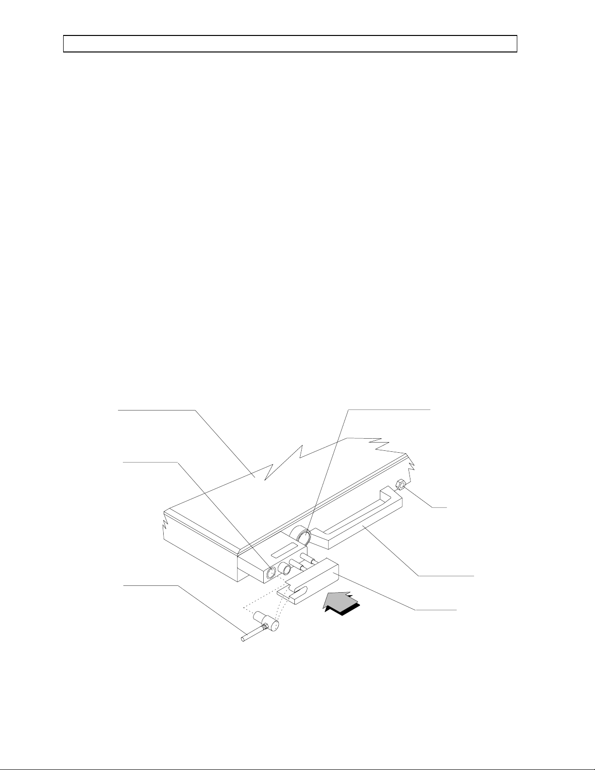
Manual Sphygmomanometer (Optional)
An aneroid manual sphygmomanometer can
be mountedon the NARKOMED 3 (see Figure
16).
The sphygmomanometer gauge mounts on the
left-handside of theanesthesia machine, above
the ventilator bellows, either on a mount on
the machine itself or on the underside of the
optional boom arm.
To install the gauge, tighten the gauge’s
threaded mounting ring in a clockwise
direction over the gauge mount. Then, attach
the fitting on the free end of the gauge hose to
the fitting labeled "BP GAUGE" on the upper
left side of the anesthesia machine.
To install the blood pressure cuff, first attach
the short hose on the cuff to the longer
extension hose. The two hoses join with Luer
lock fittings. Then, attach the free end of the
extension hose to the fitting labeled "BP
CUFF" on the patient interface panel.
The Manual Sphygmomanometer uses the
same blood pressure cuff as the
SPHYGMOMED noninvasive blood pressure
monitor. Some users mayprefer to use one cuff
for both the SPHYGMOMED and Manual
Sphygmomanometer by switching the cuff
extension hose from the SPHYGMOMED
interface panel fitting to the identical "BP
CUFF" fitting below it on the interface panel.
To install the cuff inflation bulb, insert the
male Luer fitting (slip-fit type) on the bulb
hose into the female Luer fitting (labeled "BP
BULB") to the right of the O2 flush button on
the front of the anesthesia machine.
After installation, check the gauge’s pressure
indication. With zero pressure applied to the
gauge and cuff, the gauge pointer should
remain within the band marked on the face
plate. The gauge accuracy is ±1 % of full scale
within a range of 75-225 mm Hg and ±3% of
full scale outside of this range.
To check the manual sphygmomanometer for
leaks, place the blood pressure cuff around a
rigid cylindrical object of approximately the
same diameter as a human arm. Inflate the
cuff to a pressure of 250 mm Hg, as indicated
on the sphygmomanometer gauge.
30
Page 39

THREADED HOSE
FITTINGS FOR
GAUGE AND CUFF
INTERNAL PIPING
CONNECTS BULB FITTING
TO GAUGE AND CUFF FITTING
SPHYGMOMANOMETER
GAUGE
OP30017
CUFF EXTENSION
HOSE (12 FT. LONG)
GAUGE HOSE
FEMALE LUER FITTING
(SLIP-FIT) FOR CUFF
INFLATION BULB
RETURN TO CD-ROM TABLE OF CONTENTS
MONITORING SYSTEM (continued)
Then, watch the gauge reading for 10
seconds; the gauge indication shall not
decrease more than 10 mm Hg within this
time period.
To isolate a specific source of leaks, eliminate
components from the system and perform the
test described above.
For example, to exclude the cuff inflation
bulb, pinch the cuff inflation hose after
inflating the cuff to 250 mm Hg. To exclude
the cuff itself, remove the extension hosefrom
the interface panel, occlude the "BP CUFF"
fitting, and then pressurize the gauge to a
reading of 250 mm Hg.
FigureFigure 1616 Manual Sphygmomanometer
31
Page 40

MONITORING SYSTEM (continued)
RETURN TO CD-ROM TABLE OF CONTENTS
Breathing System Sensor Interface Panel
A panel of four sensor connections is provided
on the lower left side of the NARKOMED 3
(Figure 17). These connections pertain to the
patient breathing system and thus are
mounted close to the absorber assembly. The
MED sensor cord leads from the O2MED
O
2
sensor (mounted in the inspiratory valve)and
plugs into a pin-type connector on the panel.
The BAROMED breathing pressure pilot line
leads from either the absorber (shorter pilot
line) or the Y-piece (longer pilot line) and
plugs into a quick-connect fitting on the
panel. The SPIROMED sensor cord leads
from the SPIROMED sensor on the absorber
top dome to apin-type connector on the panel.
The MULTISPEC exhaust line leads from a
hose barb fitting on the panel to an adapter
on the scavenger system.
Patient Sensor Interface Panel
A panel of four sensor connections is provided
on the upper left side of the NARKOMED 3
monitoringbank(Figure17).TheO
SATMED
2
incorporates an interface cable/preamplifier
assembly that mounts on the boom arm and
plugs into a pin-type connector on the panel.
The MULTISPEC sample line leads from a
15 mm sample adapter at the Y-piece to a
Luer lock fitting on the semi-permeable
tubing, which then connects to the sample
lineinterfacepanel.TheSPHYGMOMEDcuff
extension hose leads from the blood pressure
cuff to a threaded hose connection on the
panel. The optional manual
sphygmomanometer hose connections occupy
the bottom slot on the interface panel and are
intended for the gauge hose and the cuff
extension hose.
Boom Arm (Optional)
An optional boom arm can be mounted on the
left side of the monitoring bank. Patient
sensor lines(O
SATMED interfacecable, CO
2
sample line, SPHYGMOMED cuff extension
hose) can be routed from the patient to the
anesthesia machine in an organized fashion
with the boom arm. The arm can be adjusted
to the desired position to retain the lines in
the most convenient position.
System Communications
Although designed to operate independently,
each monitor is equipped with data
communications capabilities, allowing it to
become a component of a structured and
organized anesthesia Data Management
System. This system approach allows other
devices in the system to analyze, display, and
record the data and alarm conditions from
any monitor.
Alarm Strategy
The monitoring system has been designed to
support a uniform and structured alarm
strategy.This strategy solvesamajor problem
in the operating room today — the confusion
caused by simultaneous audible and visual
alarms from a variety of independent devices.
The structuredalarm strategy is based on the
centralization of visual alarm indicators and
the interlocking of audible alarm signals.
"Interlocking"coordinatesthealarm signals of
the various monitors that make up the
monitoring system so that only the sound of
the highest priority, currently active alarm is
annunciated, while all others are suppressed.
2
32
Page 41

OXIMETER
SENSOR
SAMPLE
BP CUFF
BP CUFF
BP GAUGE
O2SATMED
SENSOR
INTERFACE
MULTISPEC
SAMPLE-LINE
INTERFACE
SPHYGMOMED
CUFF INTERFACE
MANUAL
SPHYGMOMANOMETER
INTERFACE
O2MED SENSOR
INTERFACE
SPIROMED SENSOR
INTERFACE
BAROMED PILOT
LINE INTERFACE
MULTISPEC
EXHAUST PORT
OXYGEN
SENSOR
VOLUME
SENSOR
BREATHING
PRESSURE
EXHAUST
OP30018
RETURN TO CD-ROM TABLE OF CONTENTS
MONITORING SYSTEM (continued)
FigureFigure 1717 Patient and Breathing System Sensor Interface Panels
33
Page 42

MONITORING SYSTEM (continued)
RETURN TO CD-ROM TABLE OF CONTENTS
The corresponding visual alarm signal is
displayedat acentralizedalarm annunciation
location - the central alarm display screen.
Multiple alarm messages can be displayed
simultaneously at the central display screen.
Thiscombination of audiointerlockand visual
centralization facilitates the recognition of
alarm conditions, and drastically reduces the
response time for corrective action.
Each alarm condition has been classified
according to the urgency of the appropriate
response as follows:
WARNING: Requires immediate action.
Warning conditions are annunciated by a
continuously repeating tone pattern and a
flashing red indicator.
CAUTION: Requires prompt action.
Cautionary conditions are annunciated by an
intermittently repeating tone pattern and a
steady red indicator.
ADVISORY: Requires operator awareness,
butnotnecessarilyaction.Advisoryconditions
are indicated by a continuously illuminated
yellow indicator and may be accompanied by
a single, brief tone.
Each alarm message consists of a 12characteralphanumeric phrase thatdescribes
the corresponding alarm condition.
APPENDIX 2 lists alarm messages for the
NARKOMED 3.
Data Communication
In addition to generating alarm messages,
each monitor transmits the results of its
measurements and calculations, as well as
any applicable alarm limits. This capability
provides the basis for the central monitoring
system’s displays. It also allows automatic
recording and data documentation.Each data
message consistsof a 12-characteridentifying
phrase, the numeric results of the
measurement, and the units of measure.
Five Port Serial Interface (Optional)
The NARKOMED 3 may be equipped with a
Five Port Serial Interface for data
communications between the NARKOMED 3
and up to five external devices. Four of the
ports (A-D) are general purpose RS-232 ports
which can be configured using the
NARKOMED 3 configure function (see
Configure Menu). The last port (E) is reserved
for future use.
The NARKOMED 3 supports two different
communication protocols: VITALINK and
printer. Ports A-D can be configured for
VITALINK and ports A, C, and D can be
configured for the printer protocol.
VITALINK is an asynchronous, full duplex,
serial communications protocol for the
transfer of data, alarms, CO
waveform, and
2
certain control functions between two medical
monitoring devices. Refer to the VITALINK
Technical Reference Manual for VITALINK
programming details.
34
Page 43

OP30019
NAME
:
DATE : 24-JUL-87
PROCEDURE
:
Page 1
TIME
BLOOD PRESSURE
mmHg
120/80
120/80
WARNING:
CAUTION:
120/80
120/80
120/80
120/80
CAUTION:
CAUTION:
SYS/DIAS MEAN
PULSE SaO2 O2
AGENT CO2 RESP
RATE
MIN
VOL
TEMPERATURE
DEG C
CH 1 CH 2
/min %
EX/IN
ET/IN 1
12:00
12:02
12:02
12:02
12:15
12:20
12:25
12:27
12:27
12:27
95
92
% OXYGEN LOW
NIBP SYS LO
92
92
92
92
APNEA - PRES
APNEA - CO2
72
74
71
72
72
72
99
99
98
95
95
97
30
21
21
21
21
20
12.0/30.3
12.2/30.2
12.5/30.0
11.9/30.3
11.9/30.3
12.0/29.1
34/00
34/00
33/00
36/00
36/00
30/00
20
20
20
20
20
20
10.4
10.6
11.0
10.5
10.5
10.3
37.2
37.2
37.2
37.2
37.2
37.2
37.2
37.2
37.2
37.2
37.2
37.2
%%
mmHg
/min
RETURN TO CD-ROM TABLE OF CONTENTS
MONITORING SYSTEM (continued)
The printer protocol isdesigned to drive an 80
column (or more) RS-232 ASCII printer for
data logging. The configure screen is used to
select the printer protocol for the desired port
(A,C, or D), as well as the required baud rate,
parity, data bits, and stop bits.
The print interval (1, 2, 5, or 10 minutes) is
alsoselectedusing theconfigurescreen.When
using a printer with the NARKOMED 3, a
line of data is printed once every print
interval, reflecting the current values of all
the measurements (Figure 18).
FigureFigure 1818 Printer Output
35
Page 44

MONITORING SYSTEM (continued)
DATA
BARGRAPH
TREND
TRACE
CHECKOUT
CONFIGURE
LOG DATA
ENTER
ELECTRONIC
DATA LOG KEY
TIMED AUDIO
SILENCE KEY
AUDIO ENABLE
KEY
OP30020
Central Monitoring Display
RETURN TO CD-ROM TABLE OF CONTENTS
The central monitoring display organizes the
presentationofmeasured variables andalarm
conditions. The display’s two screens make up
the left portion of the upper housing of the
anesthesia machine (see Figure 19). The lefthand screen is reserved for the central alarm
display, Checkout Display, and Configure
Menu. The right-hand screen can be used in
one of four display modes: Bargraph, Data,
Trend, and Trace. Soft-touch keys located
along the bottom edge of the screens, and on
a system control keypad to the right of the
screens, control various display and system
functions.
Power-On-Initialization
After the System Power switch is turned to
the "ON" position, the following occurs:
All of the monitors perform a six-second
self-diagnostic test and lamp test.
The left-hand display screen shows the
Central Alarm Display.
All continuous audible alarms are
silenced for a period of 120 seconds.
(During this period, any occurrence of a
new alarm will produce a non-repeating
tone pattern appropriate for its priority).
A three-minute disableperiod isinvoked for
the SPIROMED, MULTISPEC and
SATMEDpatientalarms, as indicatedby
O
2
the appropriate Advisory messages on the
centralalarm display andby illumination of
theyellow indicators onthe monitor’s alarm
disable/enable keys. These alarms will be
automatically enabled after three minutes,
and can be immediately enabled with each
monitor’s alarm disable/enable key.
The BAROMED’s apnea pressure alarm is
automaticallydisabledonpower-up to avoid
a spurious apnea alarm with a
spontaneouslybreathing patient.Theapnea
pressure alarm will remain disabled until
manually enabled with the BAROMED’s
apnea alarm disable/enable key or the
ventilator power switch.
The right-hand display screen shows the
Data Display.
FigureFigure 1919 Display Screens and System Control Keypad
36
Page 45

RETURN TO CD-ROM TABLE OF CONTENTS
MONITORING SYSTEM (continued)
Each monitor automatically selects
commonly used alarm limits and display
selections. The operator can, at any time,
override these default settings with each
monitor’s front panel controls. If desired,
your NAD service representative can
change the monitoring system’s power-up
default configuration.
Monitor Alarm Disable Keys
To prevent nuisance alarms during machine
setup and during certain clinical situations, the
BAROMED, SPIROMED, MULTISPEC and
SATMED incorporate the alarm disable keys.
O
2
The chart below summarizes the functions of
these keys.
Note these important points:
The BAROMED "APNEA ALARM DISABLE"
key will not disable the apnea pressure
(threshold pressure) alarm if the AV-E
ventilator’s power switch is in the "ON" position.
This interlock ensures that the BAROMED apneaalarm willbe used duringautomatic ventilation.
The ventilator power switch automatically
enables the SPIROMED volume alarms and
the BAROMED apnea pressure alarm.
If a monitor fault condition (such as a
disconnected sensor) is corrected, a formerly
disabled alarm will become enabled upon
correction of the fault condition. For example, if
the "OXI ALRMS DISABLE" key has been
actuated in order to silence nuisance alarms
during machine setupand thenthe O
SATMED
2
patientsensor becomes disconnected,subsequent
reconnection of the patient sensor will
immediately re-enable O
SATMED alarms.
2
This feature ensures that alarms will return
from a fault condition in an enabled state.
Central Alarm Display
The central alarm display performs a dual
function. In its upper half, it organizes system
alarm messages into three display areas. In its
lower half, it provides a display of key
measurements (from the MULTISPEC and
SATMED) for a quick check of patient
O
2
condition (see Figures 20 & 21).
Asalarmconditionsoccur, alarm messages(such
as "% OXYGEN LO") are indicated on the
central alarm display and organized into one of
three categories: WARNING, CAUTION, and
ADVISORY.
MONITOR ALARMS DISABLED ADVISORY MESSAGE
BAROMED Apnea pressure (threshold pressure) "APNEA-P OFF"
MULTISPEC Apnea CO2, high inspiratory CO2,
high & low ETCO
2
"CO2 ALRM OFF"
"AGT ALRM OFF"
SPIROMED Apnea volume, minute volume "VOL ALRM OFF"
O2SATMED Absence of pulse, high & low SpO2,
"OXI ALRM OFF"
high & low pulse
37
Page 46

MONITORING SYSTEM (continued)
K
RETURN TO CD-ROM TABLE OF CONTENTS
Each type of alarm message produces a different
sound pattern:
Warning: A continuously repeating tone
pattern.
Caution: An intermittently repeating tone
pattern.
Advisory: A single tone or none.
Alarm messages are listed in order of the time
of occurrence, with the most recent alarm
messages appearing at the bottom of the list. To
alert the operator of the time at which a Warning or Caution occurs, an arrow appears to the
left of the most recent alarm message on the
screen (Figure 20). If the alarm condition
creatingthis messageis then resolved,the arrow
disappears and does not reappear until the occurrence of a new alarm condition.
NOTE: If the number of alarm messages in any
of the three categories exceeds the space
provided on the display screen for that category,
additional alarm messages will be held in the
machine’s memory until space is available (i.e.,
through the resolution of some of the displayed
alarm conditions).
Real-Time Pulse Bargraph and
Carbon Dioxide Trace
The central alarm display incorporates two realtimedisplays for aquick,qualitative assessment
of patient condition. In the lower left corner of
the central alarm display, a realtime bargraph
pulsates each time that a pulse is detected by
SATMED sensor. The digital values for
the O
2
oxygen saturation and pulse rate (from the
SATMED) appear to the right of the
O
2
bargraph. The lower right corner of the display
incorporates a real time carbon dioxide
waveform. The horizontal dotted line represents
partial pressure of 40 mm Hg. The digital
aCO
2
value for end-tidal CO
appears to the left of the
2
waveform.
By glancing at this display, the operator can
check for a regular pulse (with the real-time
pulsebargraph) andalso check thepatient’s ventilation (with the real-time carbon dioxide
waveform).
NOTE: If desired, a more detailed carbon
dioxide waveform and a pulse oximeter
waveform can beviewed onthe Real-TimeTrace
Display.
ARROW INDICATES
MOST RECENT
OCCURRENCE OF
WARNING OR CAUTION
WARNING CAUTION ADVISORY
% OXYG EN LO W
OXI SAT LOW
SaO ETCO
85
35
PULSE BPM
10
90
O2SATMED
PERFUSION
INDICATOR
LOG DATA
FigureFigure 2020 Central Alarm Display
38
CONTNG PRES
NIBP SYS LO
THRESHOLD LO
SIL E NCE 120
10:53
REAL-TIME
CLOC
DOTTED LINE
FOR 40 MM HG
REFERENCE POINT
CARBON DIOXIDE
WAVEFORM TRACE
OP30021A
Page 47

Real-Time Clock
RETURN TO CD-ROM TABLE OF CONTENTS
MONITORING SYSTEM (continued)
The central alarm display also includes a realtime clock. This unlabeled digital display is
located beneath the Advisory display area (see
Figure 20) and shows the time in military time.
The real-time clock may be set through the
Configure Menu.
Audio Silence Control
Two keys beneath the central alarm display
(Figure 21) can be used to temporarily silence
and enable continuous audible alarms. Pressing
the Audible Alarm Silence key (labeled with a
crossed-out speaker) once silences existing
alarms for a period of 60 seconds. Pressing the
Audible Alarm Silence key twice silences existing alarms for a period of 120 seconds.
The occurrence of a new alarm during a silence
period results in a non-repeating tone pattern
corresponding to the alarm. The audio silence
condition and the silent time remaining are displayed at the bottom of the ADVISORY section
of the central alarm display. Audible alarms can
be immediately enabled at any time by pressing
the Audible Alarm Enable key (labeled with a
speaker producing sound) located to the right of
the silence key.
Log Data Key
Pressing the "LOG DATA" key, on the lower left
of the display screen, logs the current
measurements into the system’s memory for
later reference. For details, see the Electronic
Data Log section of this manual.
OP30021B
LOGS
MEASUREMENTS
IN MEMORY
WARNING C AUTION ADV ISORY
% OXYGEN LOW
OXI SAT LOW
SaO ETCO
85
PULSE BPM
90
LOG DATA
CONTNG PRE S
NIBP SY S L O
35
10
THRESHOLD LO
SILENCE 120
AUDIBLE
ALARM
SILENCE KEY
DISPLAY OF
SILENT TIME
REMAINING
10:53
AUDIBLE
ALARM
ENABLE KEY
FigureFigure 2121 Central Alarm Display and Keys
39
Page 48

RETURN TO CD-ROM TABLE OF CONTENTS
MONITORING SYSTEM (continued)
System Control Keypad
Oriented vertically and to the right of the display screens, the system control keypad calls up a series of
displays and menus on the two display screens.
Calls up data display on
right-hand screen.
Calls up bargraph display
on right-hand screen.
Calls up trend display on
right-hand screen.
Calls up trace display on
right-hand screen.
DATA
BARGRAPH
TREND
TRACE
100
O
SaO
ETCO
INCO
80
0
CO
18
21
100
85
90
35
4
100 100
50
SaO
2
O
2
MM HG (%) VOL % /MIN MM HG
98
35
SaO
2
100
90
80
50
B
C
R
M
40
P
H
30
R
2
20
E
O
S
10
0
50
C
M
O
M
40
2
H
30
G
20
10
0
OXI
100
18
PULS E
21
BPM
MI N
VOL
TID
VOL
SYS
10
DIAS
3.0
12.5
MEAN
1.25
200
150
00
0
O
2
OXI
PULSE
9055
2:20
140
90
180
90
110
72
78
SYST
DIAS
160
75
sec
sec
40
Calls up checkout display
on left-hand screen.
CHECKOUT
Calls up configure menu
on left-hand screen.
OP30022
CONFIGURE
FigureFigure 2222 System Control Keypad
40
SELECT ENTER
PRE-USE CHECKOUT
SaO2 /NIBP IN TE R L OCK
NEONATAL MODE
SET AUDIO VOLUME
SET TIME AND DATE
SET PRINT INTERVAL
CONFIG SERIAL PORTS
CHECKOUT
END
END
CONFIGU RE
Page 49

RETURN TO CD-ROM TABLE OF CONTENTS
MONITORING SYSTEM (continued)
Checkout Display (Refer to Figure 23)
Pressing the "CHECKOUT" key calls up the
checkout display on the left-hand screen. This
selection provides a text display of pre-use
checkout procedures to be performed by the
operator in the room in which the anesthesia
machine is to be used. The two right-hand keys
beneath the checkout display can then be used
to page the display forward and exit from the
display.
Configure Menu (Refer to Figure 24)
Pressing the "CONFIGURE" key calls up a
menu on the left-hand screen that allows the
operator to change certain anesthesia system
features.
PRE-USE CHECKOUT
Selecting the "SpO2/NIBP INTERLOCK" item
on the menu allows the operator to coordinate
the O
SATMED’s alarms with the
2
SPHYGMOMED’s cuff inflation for those
instances where the O
SATMED finger sensor
2
must be placed on the samearm asthe SPHYGMOMEDbloodpressurecuff.Whentheinterlock
is enabled, the monitoring system automatically
disablesO
SATMEDalarms (as indicatedby the
2
Advisory message "OXI ALRM OFF" and
illumination of the yellow indicator on the "OXI
ALARMS DISABLE" key) during SPHYGMOMED cuff inflation and for a short period
after cuff deflation. After this interlock is
enabled, if the anesthesia machine’s System
Power switch is turned to the "STANDBY"
position, the system will disable the SpO
/NIBP
2
interlock when the anesthesia machine is next
powered up.
LOG DATA
FigureFigure 2323 Checkout Display
NEXT PAGE
END
CHECKOUT
OP30024
41
Page 50

MONITORING SYSTEM (continued)
LOG DATA
SaO2/NIB P INTE RLOCK
NEONATAL MODE
SET AUDIO VOLUME
SET TIME AND DATE
SE T P RINT INTERV AL
CONFIG SERIAL PO RTS
SELECT ENTER
END
CONFIGURE
OP30023
RETURN TO CD-ROM TABLE OF CONTENTS
Certain NAD monitors are capable of operating
in a "NEONATAL MODE" (e.g., reduced NIBP
cuff pressure). Selecting the "NEONATAL
MODE" configuration option allows the operator
to invoke the neonatal operating mode of all
such monitors in the system. Refer to the
operator’smanuals of theindividual monitors for
a detailed description of the neonatal operating
mode. Switching the NARKOMED 3 to standby
automatically disables the neonatal mode.
Selecting the "SET AUDIO VOLUME" item
allows the operator to adjust the alarm
annunciator volume for varying levels of
background noise. The audio volume setting
chosenthroughthismenubecomes the power-up
default that will be set whenever the System
Power switch is turned on.
Selecting the "SET TIME AND DATE" item on
the configure menu allows the operator to set
the machine’s real-time clock. Pressing the lefthand selection key pages through the day,
month, year, hour, and minute settings.
Then, two of the selection keys can be used to
increase or decrease each setting. The real-time
clock setting is saved when the operator selects
anotherdisplayusing the system controlkeypad.
The "SET PRINT INTERVAL" selection allows
the operator to adjust the interval at which an
interfaced printer will print out data for certain
physiologic and system parameters. When
entered, this selection offers the following choice
of print intervals: 1, 2, 5, or 10 minutes. For
example, a print interval of two minutes means
that the printer will print out a line of
alphanumeric data every two minutes.
Selecting the "CONFIGURE SERIAL PORTS"
option on the Configure Menu allows the
operator to select the baud rate, parity, data bits,
stop bits, and protocol for ports A-D on the
optional Five Port Serial Interface. When
selecting the protocol, enter "1" for Printer and
"3" for VITALINK.
Figure 24 Configure Menu
42
Page 51

Y
RETURN TO CD-ROM TABLE OF CONTENTS
MONITORING SYSTEM (continued)
Data Display (Refer to Figure 25)
Pressing the "DATA" key calls up a numerical
display of key measurements and alarm limits,
thus displayingnumerical data in a central location to facilitate record keeping. Alarm limits
appear to the right of measured variables and
are smaller in size on the screen. The noninvasive blood pressure sample age is displayed in
minutes and seconds.
The pulse rate for the Data Display is first supplied by the O
SATMED pulse oximeter and the
2
reading is labeled "OXI PULSE." If a pulse rate
measurement is not available from the
SATMED, the SPHYGMOMED noninvasive
O
2
blood pressure monitor supplies the pulse rate
measurement, which is then labeled "NIBP
PULSE."The DataDisplaywaits approximately
one minute before switching to the SPHYGMOMED pulse rate measurement.
Electronic Data Log
When the operator must devote full attention to
the patient, it can be difficult to record or note
the measurements provided by the monitoring
system. To address this need, the NARKOMED
3 allows the operator to log a set of measurements into memory by pressing a single key.
Then, at a more convenient time, the operator
can manually recall this logged data for
referenceormanualcompletionoftheanesthesia
record.
Pressing the "LOG DATA" key (located at the
far left of the display screens) takes a "snapshot"
of the data on the Data Display screen and
stores it in the system’s memory. At the first actuation of the "LOG DATA" key after the
NARKOMED 3 has been turned on, a "DATA
LOG"label appearsabovethe left-handselection
key for the Data Display.
OP30025
WARNING CAUTI ON ADVISORY
% OXYGEN LOW
OXI SAT LOW
SaO ETCO
85
PULSE BPM
35
CONTNG PRES
NIBP SYS LO
THR ESHOLD LO
SILENCE 120
90 10
LOG DATA
LOG DATA
KEY
DATA LOG
LABEL
FigureFigure 2525 Data Display
10:53
DATA KE
DATA
12.5
1.25
10
3.0
OXI
90
PULSE
SYS
90
DIAS
72
MEAN
78
NEXT PR EVIOUS
140
40
BARGRAPH
180
110
TREND
TRACE
CHECKOUT
CONFIGURE
RIGHT-HAND
SELECTION KEYS
100
O
18
21
100
SaO
ETCO
INCO
DATA LOG
ENTER
85
35
BPM
90
MIN
VOL
TID
4
VOL
LEFT-HAND
SELECTION KEY
43
Page 52

MONITORING SYSTEM (continued)
Pressing this selection key thendisplays thepreviously logged data as it appeared at the
actuationof the "LOGDATA" key. Each"logged"
screen is labeled with an Event number (up to
Event 99) and the time at which it had been
logged into memory. The ten most recently
logged Events can be reviewed by using the
right-hand selection keys to view either the
"PREVIOUS" or "NEXT" Event. For example, if
13 Events have been stored, pressing the
"PREVIOUS" selectionkey will page the display
backwards through the stored screens until
reaching Event 4, the tenth screen back from
Event 13.
RETURN TO CD-ROM TABLE OF CONTENTS
Saturation Bargraph Display
O
2
The oxygen saturation bargraph displays the
percent arterial hemoglobin saturation as
measured by the O
SATMED.
2
% Oxygen Bargraph Display
The oxygen concentration bargraph displays the
breathing system oxygen concentration (usually
inspiratory) measured by the O
MED oxygen
2
concentration monitor.
Pulse Rate Bargraph Display
The Event display screen automatically returns
to the Data Display after 30 seconds. To return
to the Data Display immediately, press the
"DATA" key on the System Control Keypad.
Note thatturning the anesthesia machine’s System Power switch to the "STANDBY" position
will erase all of the logged Events and start the
event numbering from Event 1 again.
Bargraph Display (Refer to Figure 26)
Pressing the "BARGRAPH" key calls up an array of vertical bargraphs for up to five vital
variables: carbon dioxide, oxygen saturation,
breathing system oxygen concentration, pulse
rate, and blood pressure. The operator can, at a
glance, obtain a qualitative assessment of the
anesthesia machine/patient condition with the
bargraph display.
A specific measured variable is assigned to a
unique location on the display screen. Alarm
limits show up as triangular pointers to the left
of each vertical bargraph.
Inspiratory/End-Tidal CO
2
Bargraph Display
The pulse rate for the Bargraph Display is first
supplied by the O
SATMED pulse oximeter and
2
is labeled "OXI PULSE." If a pulse rate
measurement is not available from the
SATMED, the SPHYGMOMED noninvasive
O
2
blood pressure monitor supplies the pulse rate
measurement, which is then labeled "NIBP
PULSE." The Bargraph Display waits one
minutebefore switchingtothe SPHYGMOMED
pulse rate measurement.
Systolic/Diastolic Blood Pressure Bargraph
Display
The systolic/diastolic blood pressure bargraph
displays the systolic and diastolic blood pressure
as measured by the SPHYGMOMED noninvasive blood pressure monitor.The lower edge of
the shaded bar represents the diastolic blood
pressure and the upper edge represents the systolic blood pressure. A reverse video bar represents the mean arterial pressure and another
reverse video bar represents the instantaneous
cuff inflation pressure. The NIBP sample age in
minutes and seconds appears beneath the
bargraph display.
Thecarbon dioxidebargraphdisplays thepartial
pressure of carbon dioxide as measured by the
MULTISPEC monitor. The lower edge of the
shaded bar corresponds to the instantaneous
value.
CO
2
44
Page 53

ENTER
80
0
0
0
0
100 100
150
200
50
CO
2
SaO
2
O
2
OXI
PULSE
SYST
DIAS
MM HG
(%)
VOL %
/MIN
MM HG
160
75
9055
98
35
2:20
ALARM LIMIT
INDICATOR
INSTANTANEOUS CO
2
PARTIAL PRESSURE
NIBP SAMPLE AGE
IN MINUTES AND
SECONDS
INSTANTANEOUS
CUFF PRESSURE
MEAN BLOOD
PRESSURE
(MAP)
OP30027
RETURN TO CD-ROM TABLE OF CONTENTS
MONITORING SYSTEM (continued)
FigureFigure 2626 Bargraph Display
45
Page 54

MONITORING SYSTEM (continued)
RETURN TO CD-ROM TABLE OF CONTENTS
TREND MONITOR
Pressing the "TREND" key invokes the Trend
monitor’s display screen (Figure 27). The Trend
monitor is activated on power-up and provides
up to 8 hours of trend history for up to 17
measurements, showing two trends at a time.
The Trend monitor consists of five screens:
• Trend Display
• Set Up Trend
• Rapid Track
• Tabular Data Log
• Set Up Data Log.
A description of each screen follows:
200
BP
Trend Display Screen
The Trend Display screen is invoked when the
"TREND" key is pressed. Two trend graphs,
eachrepresenting a specific measurement’strend
history, are displayed simultaneously.
The label for the selected measurement appears
at the top of the correspondingtrend graph, next
to the vertical axis. The horizontal axis is
calibrated in military time. The vertical axis is
calibrated in the appropriate units for the
selected measurement. A line graph, representing the historical variations of the trended
measurement, travels from left to right across
the graph as new trend data accumulates.
100
0
10:00
SaO
100
90
80
10:00
2
ENTER
Figure 27 Trend Display Screen
10:15
10:15
10:30
RAPID
TRACK
DISPLAY
DATA LOG
SET UP
TREND
SET UP
DATA LOG
10:30
OP30028
46
Page 55

ENTER
SE T UP TRE ND
SCALE
EXIT
ON
OP30029
AUT O
SCALE
DATA
ERASE
GRID
ON
OFF
OF F
10 MIN
30 MIN
1 HR
2 HR
4 HR
8 HR
BP
CO2
SaO2
PULSE
AGENT
O2
MINVOL
RR
BR PR
TEMP 1
TEMP 2
BP
CO2
SaO2
PULSE
AGENT
O2
MINVOL
RR
BR PR
TEMP 1
TEMP 2
BOTTOMTOP
RETURN TO CD-ROM TABLE OF CONTENTS
MONITORING SYSTEM (continued)
The box in the bottom right corner of the Trend
display screen contains labels for the remaining
four Trend Monitor screens. By using the soft
key beneath the labels, the operator can select a
specific screen. Pressing the "ENTER" key activates the selected screen.
The Trend Display screen can be configured by
the operator using the Set Up Trend screen.
Set Up Trend Screen
The Set Up Trend screen (Figure 28) allows the
operator to select measurements for the top and
bottom trendgraphs, the timescale interval, the
Auto Scale feature, Data Erase function, and the
Trend Grid display.
To select a specific configuration, the operator
must:
1. Press the soft key beneath the
correspondingcolumn.Thecursorwillmove
to the top selection of the column.
2. Continue pressing the soft key until the
cursor moves to the desired configuration.
3. Press the "ENTER" key to enable the
selected configuration. The cursor will
automatically return to the "EXIT" screen
label.
The operator can press the "ENTER" key again
to exitthe Set UpTrend Screen, or else continue
configuration via the soft keys.
Figure 28 Set Up Trend Screen
47
Page 56

MONITORING SYSTEM (continued)
RETURN TO CD-ROM TABLE OF CONTENTS
Trend Graph Selection
Measurement display selections for the top and
bottom trend graphs appear in the two left
columns on the screen, labeled TOP and
BOTTOM. Although the Set Up Trend screen
allows the operator to select displayed
parameters, all parameters are trended.
NOTE: The power-on default selections for the
Trend graphs are blood pressure (BP) and
oxygen saturation (SpO
).
2
In general, trends appear on the display as a
single line graph plotted against time. The
following are five exceptions:
1. The noninvasive blood pressure trend is
displayed as a vertical bar appearing at the
point in time the sample wastaken. The top and
bottom ofthe bar represent systolic and diastolic
pressure, respectively, and the gap in the bar
represents the mean arterial pressure.
2. The invasive blood pressure trend appears as
a shaded area on the screen showing the blood
pressure envelope, with the top of the area
representing systolic pressure, the bottom
representing diastolic pressure, and the
unshadedgap in thearearepresenting themean
arterial pressure.
3. The CO
the screen showing the CO
top of the area representing end-tidal CO
the bottom representing inspiratory CO
trend appears as a shaded area on
2
envelope, with the
2
2
.
2
and
During the recovery phase of an operation, the
top of the envelope area represents expired
agent, while the bottom represents inspired
agent.
5. The Breathing Pressure trend appears as a
shaded area on the screen showing the
breathing pressure envelope, with the top of the
area representing peak breathing pressure, the
bottom representing PEEP, and the unshaded
gapin the arearepresenting themeanbreathing
pressure.
Trend Scale Selection
The operator can select one of six time scales for
the trend graphs: 10 minutes, 30 minutes, 1
hour, 2 hours, 4 hours or 8 hours. The selected
scale is indicated on the horizontal axis of the
trend graphs.
The Trend Monitor rounds out the time scale
labeling for ease of reading. As a result, the
trend graph will sometimes show a gap on the
left-hand portion of the display. This gap does
not represent a loss of data but rather shows
that data for that gap has not been trended.
When a trend graph is completely filled and the
Auto Scale mode is disabled, the Trend Monitor
automatically shifts the horizontalaxis and data
in orderto keep acontinuous display oftrend information.
NOTE: The power-on default selection for the
time scale is 30 minutes.
4. The anesthetic agent trend appears as a
shaded area on the screen showing the agent
envelope. During the induction phase of an
operation, the top of the envelope area
represents inspired agent and the bottom
represents expired agent. For the maintenance
phase of an operation, the inspired agent
typically approaches the expired agent.
48
Automatic Scaling
Enabling Auto Scale allows the Trend Monitor
to adjust a filled trend graph to the next time
scale for a complete display of trend history.
NOTE: The power-on default selection for Auto
Scale is ON.
Page 57

Selectable Trend Grid
ENTER
EV
OP30030
TIME SYS/DIAS
(MEAN)
PULSE
TEMP SaO2 CO2 AGENT(I/E)
1210:24
10:24
132/78
130/77
100
100
70
72
36.4
35.7
98
99
36
38
1.5/1.3
1.5/1.3
PAGE
EXIT
1
RETURN TO CD-ROM TABLE OF CONTENTS
MONITORING SYSTEM (continued)
To aidin the interpretation of a trend graph, the
Trend Monitor features a selectable trend grid.
NOTE: The power-on default selection for the
trend grid is ON.
Data Erase Command
Activating the Data Erase command clears all
existing trend data from the Trend Monitor.
This feature is particularlyuseful for erasing the
unwanted trend data that accumulates during
the setup and checkout of the machine prior to
actual use with the patient.
Rapid Track Screen
Selecting theRapid Track screentrends the currently selected measurements on a 10-minute
time scale, displaying the last five minutes of
data. When the line graph fills the 10-minute
time scale, the trend monitor
automatically shifts the data to provide a 5minute history and space for the next 5 minutes
of trend data. Rapid Track can be terminated
any time by highlighting the "RESUME
TREND" selection and pressing the "ENTER"
key. If selected,Auto Scaleis reactivatedand the
previously selected trend scale returns to the
screen. Other ways to eliminate the Rapid Track
function include changing the time scalefrom 10
minutes in the Set Up Trend screen or by
turning Auto Scale "ON."
Tabular Data Log Screen
The Trend Monitor incorporates a tabular Data
Log. This capability allows the operator to save
a set of measurements (called an "event") for future reference. Selecting the Display Data Log
screen (Figure 29) presents all previously logged
data in a tabular form. The events are
numbered sequentially as they are logged (up to
99).
Figure 29 Display Data Log Screen
49
Page 58

MONITORING SYSTEM (continued)
RETURN TO CD-ROM TABLE OF CONTENTS
The time of occurrence, as well as seven
measurements, are displayed for each event.
Pressing the highlighted "PAGE" soft key allows
the operator to go through each page of logged
data where 11 entries per page are displayed. In
this mode, "PAGE" and "EXIT" soft keys will
activate functions; pressing the "ENTER" key is
not necessary.
An event can be manually logged by pressing
the "LOG DATA" key, located at the far left of
the display screens. The operator can also
configurethe TrendMonitor to automaticallylog
data via the Auto Log function of the Set Up
Data Log screen.
Set Up Data Log Screen
The Set Up Data Log screen (Figure 30) allows
the operator to select the parameters for
automatically saving a set of measurements.
Configuration selections forthe SetUp Data Log
screen are implemented in the same style as the
Set Up Trend screen (see Set Up Trend section
for more details).
Auto Log
When the Auto Log function is enabled, the
Trend Monitor can be configured to record an
event at 1, 2, 5 or 10 minute time intervals. An
event canalso be automatically recorded at each
noninvasive blood pressure measurement.
NOTE: The power-on default selection for Auto
Log is ON, witha time interval of 5minutes and
the NIBP criteria disabled.
Data Erase Command
Activating the Data Erase command clears all
existing tabular log data from the Trend
Monitor. It should be noted that this function
does not work in conjunction with the electronic
Data Log (see Electronic Data Log section for
more details).
ENTER
Figure 30 Set Up Data Log Screen
SET UP DATA LOG
EVERY
1 MIN
2 MIN
5 MIN
10 MIN
EACH
NIBP
ON
OFF
DATA
ERASE
AUTO
LOG
ON
OFF
EXIT
OP30031
50
Page 59

REAL-TIME TRACE MONITOR
RETURN TO CD-ROM TABLE OF CONTENTS
MONITORING SYSTEM (continued)
Pressing the "TRACE" key calls up a real-time
trace display on the right-hand display screen
(Figure 31). The display is capable of presenting
two simultaneous traces from a choice of up to
eight signals. Depending on monitor options, the
choices may be: CO
,N2O, Halothane,
2
Enflurane, Isoflurane, expiratory flow rate,
breathing pressure, and pulse oximeter
waveform.
Selection Keys
The three left-most keys are usedto selectwhich
signals are to be displayed in the upper and
lower traces. The keyimmediately tothe right of
the "ENTER" keycorresponds tothe upper trace
display, and the second key to the right of the
"ENTER" key corresponds to the lower trace. A
selection is made by stepping through the
available choices displayed sequentially directly
above the key. Pressing the "ENTER" key while
the selected choice is displayed will put the
selection into effect and alter the display
accordingly. If the "ENTER" key is not pressed
within a short time, the display window above
the key will be relabeled with the current trace.
Sweep Speed Control
The second key from the right controls the
sweep speed for both waveform displays.
Successive keystrokes will toggle the sweep
speed selection between "SLOW" (16 seconds)
and "FAST" (8 seconds). The currently selected
sweep speed selection is displayed against an illuminated background in the window directly
above the sweep speed selection key. The
unselected sweep speed is displayed against a
dark background.
Waveform Sweep/Freeze Control
The right-most key freezes the display after the
completion of the current sweep. Successive
keystrokes will alternately freeze and unfreeze
the display. The current display sweep/freeze
state is identified against an illuminated background in the window directly above the
sweep/freeze control key. The unselected
sweep/freezeselectionisdisplayedagainstadark
background. When in the sweep mode, a gap in
the trace represents the division between the
previous sweep and the current sweep.
Automatic Scaling
The Real-Time Trace Display calculates the
average peak measurement and then
automatically selects the appropriate vertical
axis scaling.This feature ensures maximum use
of the display’s full resolution and reduces the
amount of over-range displays.
51
Page 60

MONITORING SYSTEM (continued)
S
P
RETURN TO CD-ROM TABLE OF CONTENTS
CURRENT
SWEEP
GAP IN TRACE REPRESENTS
DIVISION BETWEEN CURRENT
PREVIOU
SWEE
SWEEP AND PREVIOUS SWEEP
B
C
R
M
P
H
R
2
E
O
S
M
C
O
M
2
H
G
50
40
30
20
10
50
40
30
20
10
0
sec
0
sec
ENTER
ENTER
KEY
OP30032
BREATHING
PRESSURE
UPPER TRACE
SELECTION KEY
UPPER TRACE
SELECTION
DISPLAY
CO2 SLOW
LOWER TRACE
SELECTION KEY
LOWER TRACE
SELECTION
DISPLAY
FAST
SWEEP SPEED
SELECTION KEY
SWEEP SPEED
SELECTION
DISPLAY
SWEEP
FREEZE
WAVEFORM
SWEEP/FREEZE
KEY
WAVEFORM
SWEEP/FREEZE
DISPLAY
Figure 31 Real-Time Trace Display
52
Page 61

Initial Setup
RETURN TO CD-ROM TABLE OF CONTENTS
NARKOMED 3 SETUP & INSTALLATION
Initial setup of a NARKOMED 3 anesthesia
machine shall be by or under the direct
supervision of an authorized North American
Dräger representative.
Vaporizers
Vaporizersshall beinstalled during theinitial
setup performed by an authorized North
American Dräger service representative.
After initial setup, if a vaporizer bypass block
must be replaced with a vaporizer, this
procedure must be performed by an
authorized North American Dräger service
representative. In addition, any such
replacement must be followed by a breathing
and fresh gas delivery system pressuretest as
described in Step 26 of this manual’s Pre-Use
Checkout Procedure.
Auxiliary and Optional Equipment
Instructions for the setup and installation of
auxiliaryandoptionalequipmentareincluded
within the operator’s manual supplied with
each device.
Pipeline Connections
Pipelineconnections for oxygen,nitrous oxide,
and an optional third gas are located on the
side of the flowmeter housing (Fig. 32).
Standard Diameter Indexed Safety System
(DISS) gas fittings are used for each gas.
Attach pipeline supply hoses as follows:
2. Connect the gas fitting on the supply
hose to the corresponding gas fitting
on the side of the flowmeter housing
(Fig. 32). Use a wrench to tighten the
attached hex nut fitting.
3. Attach the other end of the supply
hose(s) tothe appropriate, functioning
hospital pipeline supplies.
4. Check for sufficient pipeline pressure
(50-55 psi) using the pressure gauge
on the front of the NARKOMED 3.
5. Turn the NARKOMED 3 System
Power switch to "ON."
6. Turn on the oxygen flow to 10 l/min
and turn off all other gases.
7. Verify the delivery of pure oxygen to
the patient breathing system by using
the oxygen analyzer. First, flush the
patient breathing system repeatedly
by pressing the O
open the O
2
flush button. Then,
2
flow control valve to a
flow of 8 l/min. With the oxygen
sensor mounted in the inspiratory
valve dome, the Oxygen Analyzer
display area should read 100 (±3) %
oxygen.
8. Close the O
flow control valve and
2
turn the NARKOMED 3 System
Power switch to "STANDBY".
1. Turn the NARKOMED 3 System
Power switch to "STANDBY" and
close the reserve gas cylinders with
the cylinder wrench tethered to the
rear of the anesthesia machine.
53
Page 62

RETURN TO CD-ROM TABLE OF CONTENTS
NARKOMED 3 SETUP & INSTALLATION (continued)
YELLOW
GREEN
BLUE
AIR DISS
GAS FITTING
O2 DISS
GAS FITT ING
BLACK & WHITE
CHECKERED
WHITE
BLUE
2
O DISS
N
GAS FIT TING
VACUUM DISS
FITTING
OP10092
WHITE
VACUUM DISS
FITTING
CANADA
FigureFigure 3232 Supply Line DISS Gas Fittings And Supply Line Hose Connections
(Air Option)
54
YELLOW
Page 63

Cylinder Connections
R
RETURN TO CD-ROM TABLE OF CONTENTS
NARKOMED 3 SETUP & INSTALLATION (continued)
The NARKOMED 3 is equipped with ANSI
standard pin-indexed hanger yokes for E-size
reserve gas cylinders. Reserve cylinders are
attached as follows (see Fig. 33):
1. Turn the System Power switch to
"STANDBY" and disconnect the
hospital pipeline supply hose.
2. Remove the old sealing washers from
the seat of the gas inlet in the yoke.
3. Insert a new washer onto the seat of
the yoke gas inlet connection.
4. Verify the presence and integrity of
the twoindex pins belowthe gas inlet.
5. Insert the head of a gas cylinder with
matching gas color code into the yoke
from below, such that the gas outlet
and indexing holes on the cylinder
head are facing the gas inlet and
indexing pins on the yoke assembly.
6. Engage the indexing holes with the
index pins and screw the yoke handle
clockwise against the cylinder head,
such that the point of the yoke handle
bolt is aligned with the countersunk
recess on the back of the cylinder
head.
7. Verify that the sealing washer is in
place, that the index pins are
engaged, and that the cylinder hangs
vertically. Tighten securely.
YOKE HANDLE
BOLT
YOKE PLUG
YOKE
HANDLE
CYLINDER
WRENCH
YOKE
ASSEMBLY
OP20035
INDEX
PINS
GAS
INLET
CYLINDER
VALVE
SEALING
WASHER
CYLINDER
HEAD
GAS CYLINDE
(COLOR CODED)
FigureFigure 3333 Reserve Gas Cylinder Installation
55
Page 64

RETURN TO CD-ROM TABLE OF CONTENTS
NARKOMED 3 SETUP & INSTALLATION (continued)
8. Open the cylinder valve by turning
the cylinder valve stem in a counterclockwise direction, using the cylinder
wrench tethered to the rear of the
NARKOMED 3.
9. Check for adequate cylinder pressure
on the pressure gauge on the
anesthesia machine.
10. Turn the System Power switch to
"ON" and verify the gas flow from the
exchanged cylinder by opening the
corresponding flow control valve and
observing its flowmeter.
11. If the oxygen cylinder was exchanged,
verify the delivery of pure oxygen to
the patient breathing system by using
the oxygen analyzer.
12. Close the flow control valve(s) and
turn the System Power switch to the
"STANDBY" position.
1. Turn theNARKOMED 3System Power
switch to "STANDBY."
2. Unwrap sufficient length of power cord.
3. Plug the power cable into a 117 or 240
VAChospitalgrade outlet(dependingon
thevoltage requirement ofthe machine).
4. Turn the System Power switch of the
NARKOMED 3 to "ON." The central
monitoring display should now be
active.
5. Verify that the battery-in-use ("AC
POWER FAIL") indicator onthe main
switch panel remains extinguished.
6. Verifythat all circuitbreakers,located
on the lower right side of the frame,
remain reset (i.e., pushed in).
7. Turn the System Power switch of the
NARKOMED 3 to "STANDBY."
Electrical Power Connection
The NARKOMED 3 is equipped with a power
cable with a hospital grade plug for the 117 VAC
primary electrical power or with a power cable
with a hospital grade plug for the optional 240
VAC primary electrical power. Attach the
NARKOMED 3 to electrical power as follows:
56
Page 65

RETURN TO CD-ROM TABLE OF CONTENTS
NARKOMED 3 SETUP & INSTALLATION (continued)
Five Port Serial Interface (Optional)
An optional Five Port Serial Interface allows
various externaldevices to communicate with
the NARKOMED 3. A typical method of
connection follows:
1. Plug the device’s power cord into an
AC outlet.
NOTE: Devices plugged into the
NARKOMED 3’s convenience
receptacles (117 VAC option)
contributetothe anesthesia machine’s
total leakage current. This total
leakage current should notexceed 100
µamps.
2. Attach a data cable between the
external device and one of the ports
on the NARKOMED 3 as shown in
the chart below:
PORT DEVICE PROTOCOL
A VITALINK or CO•WRITER or printer
B VITALINK or CO•WRITER
C VITALINK or CO•WRITER or printer
D VITALINK or CO•WRITER or printer
E Reserved
The NARKOMED 3 uses a 9-pin
connector (see Appendix 1 for pinout)
with a DTE configuration for each
serialport. Thus,wheninterfacing the
NARKOMED 3 with a device that
also has a DTE configuration, a
straight-throughcable cannot beused.
Instead, employ one of the following
connections:
a. Usethe type of cable that interfaces
an IBM PC AT (or compatible) with a
user-supplied device.
Attach the 9-pin connector to the
appropriateport on therearunderside
of the anesthesia machine’s
monitoring bank. Secure the cable
with the captive screws provided.
Attach the 25-pin connector to the
serialport on theuser-supplieddevice.
b. If not equipped with the type of
cable mentioned above, the 30" DB9DB25 (RS-232C) adapter cable
supplied with the Five Port Serial
Interface maybe required totranslate
pin connections.
Attach the 9-pin connector to the
appropriateport on therearunderside
of the anesthesia machine’s
monitoring bank. Secure the cable
with the captive screws provided.
Attach the 25-pin connector to the
user-supplied cable that connects to
the device.
3. Configure the selected port for the
proper baud rate, parity, data bits,
stop bits, and protocol using the
configure serial interface function (see
Configuration section). When
interfacing a printer, the print
interval can also be selected through
the configure screen.
57
Page 66

RETURN TO CD-ROM TABLE OF CONTENTS
NARKOMED 3 SETUP & INSTALLATION (continued)
Absorber System and Monitor Sensors
Install the absorber system and monitor
sensors as described below (Figs. 34 & 35).
This installation presumes the use of an
appropriate scavenger system with the
absorber system. If using a Bain circuit
adapter,consultthe manualsuppliedwiththe
adapter.
1. Slip the absorber mounting stud into
the absorber pole on the swivel arm.
2. Tighten the set screw on the absorber
pole to lock the absorber in place.
3. Pull the fresh gas locking bar, located
on the front of the NARKOMED 3,
out to its extended position (Figs. 11
& 34). Attach the fitting on the fresh
gas hose to the terminal. Release the
spring-loaded locking bar over the
fitting, allowing it to "lock" the fitting
into place.
7. Attach the breathing bag to theswivel
bag mount 22 mm terminal marked
"BREATHING BAG" (Fig. 34).
8. Connect the 19 mm scavenger hose
between the 19 mm terminal (marked
"SCAVENGERHOSE") on thebottom
of the absorber pole (Fig. 34) and the
19 mm terminal (marked
"SCAVENGER HOSE") on the
scavenger (Fig. 35).
9. Attach the breathing pressure pilot line
tothe connectoron thesystem interface
panel marked "BREATHING
PRESSURE" (Fig. 35). If the shorter
pilot line is used, it reads the pressure
at the absorber top dome gas pipe by
means of a quick-connect fitting. If the
longer pilot line is used, it reads the
pressure at or near the patient Y-piece,
at either a 15 mm adapter with the
appropriate Luer fitting or a Y-piece
with the appropriate Luer fitting.
4. Attach a 22 mm breathing hose (Fig.
35) between the ventilator bellows 22
mmterminal marked"VENTILATOR
HOSE" and the 22 mm terminal on
the rear of the manual/automatic
selector valve, which is also marked
"VENTILATOR HOSE."
5. Attach a 22 mm breathing hose (Fig.
34) between the 22 mm hose terminal
on the inspiratory valve marked
"INSPIRATION" and one side of the
Y-piece.
6. Similarly, attach another 22 mm
breathing hose (Fig. 34) between the
other side of the Y-piece and the 22
mm hose terminal on the expiratory
valve marked "EXPIRATION."
10. Connect the Oxygen Analyzer sensor
cord to the connector on the interface
panel marked "OXYGEN SENSOR"
(Fig. 35). Make sure that the oxygen
sensorassembly isproperly mountedin
the inspiratory valve dome.
11. Connect the 19 mm scavenger hose
between the 19 mm terminal (marked
"SCAVENGER HOSE") on the rear of
the APLvalve and the19 mm terminal
(marked"SCAVENGERHOSE") on the
rear of the absorber pole (Fig. 34).
12. InstalltheRespiratory VolumeMonitor
sensor between the expiratory valve
and the absorber. Plug the sensor cord
into the connector on the interface
panel marked "VOLUME SENSOR"
(Fig. 35).
58
Page 67

22MM
BREATHING
HOSE
INSPIRATORY
VALVE W/22MM
BREATHING
HOSE TERMINAL
ABSORBER
Y-PIECE
CO2 MONITOR
AIRWAY ADAPTER
ABSORRBER
MOUNTING STUD
SWIVEL BAG
MOUNT W/22MM
BREATHING BAG
TERMINAL
TO SCAVENGER
19MM
SCAVENGER
HOSE
APL VALVE
W/19MM
SCAVENGER
HOSE TERMINAL
FRESHGAS LOCKING
DEVICE W/15MM
FEMALE FITTING
MANUAL/AUTOMATIC
SELECTOR VALVE
W/22MM HOSE
TERMINAL
19MM SCAVENGER HOSE
ABSORBER POLE W/19MM
SCAVENGER HOSE TERMINAL
RESPIRATORY
VOLUME MONITOR
SENSOR
OXYGEN ANALYZER
SENSOR
OP20036
TO OXYGEN ANALYZER
INTERFACE PANEL
EXPIRATORY
VALVE W/22MM
BREATHING
HOSE
TERMINAL
TO RESPIRATORY
VOLUME MONITOR
INTERFACE PANEL
BREATHING BAG
(OPTIONAL)
FRESHGAS HOSE
W/15MM MALE
FITTING
RETURN TO CD-ROM TABLE OF CONTENTS
NARKOMED 3 SETUP & INSTALLATION (continued)
FigureFigure 3434 Absorber Installation (Front View)
59
Page 68

RETURN TO CD-ROM TABLE OF CONTENTS
NARKOMED 3 SETUP & INSTALLATION (continued)
13. Connect the respiratory gas analyzer
sample tubing to the patient
breathing system.
14. Verify the functional integrity of the
breathing system by obstructing the
patient side of the Y-piece and
ventilating the breathing circuit.
There should be a cyclic increase and
decrease in the breathing pressure.
15. Verify the delivery of oxygen by
providing oxygen to the breathing
circuit. The measured oxygen
concentration should rise towards
100%.
16. Perform acomplete Pre-Use Checkout
Procedure as described in this
manual.
Scavenger System
Installation of an open reservoir scavenger
system (Fig. 35) on the NARKOMED 3 is as
follows:
NOTE: Two different types of scavenger
systems are available for the NARKOMED 3.
The following installation procedure applies
only to the open reservoir scavenger system.
For details on the air conditioning scavenger,
consult its instruction manual.
3. Connect one end of a 19 mm
scavenger hose to the 19 mm hose
terminal on the bottom of the
absorber pole (Fig. 35) and connect
the other end to the 19 mm hose
terminal labeled "Scavenger Hose" on
the right-hand side of the scavenger
body.
4. Attach the 19 mm scavenger hose
between the 19 mm terminal (marked
"SCAVENGER HOSE") on the
ventilator relief valve (Fig. 35) and
the 19 mm terminal (marked
"SCAVENGER HOSE") on the lefthand side of the scavenger.
5. Attach the 19 mm scavenger hose
between the19 mm terminal (marked
"SCAVENGER HOSE") on the rear of
the APL valve (Fig. 34) and the 19
mmterminal (marked"SCAVENGER
HOSE") on the rear of the absorber
pole.
6. Verify the proper functioning of the
scavenger system.Check for excessive
PEEP or NEEP during ventilation.
1. Using the mounting bracket, install
the scavenger on the side of the
anesthesia unit as shown in Figure
35.
2. Attach a wall suction hose between
the wall suction outlet and the suction
terminal (DISS or hose barb
w/adapter) on the scavenger.
60
Page 69

VENTILATOR
BELLOWS W/22MM
VENTILATOR
HOSE TERMINAL
RELIEF VALVE
W/19MM
SCAVENGER
HOSE TERMINAL
19MM SCAVENGER
HOSE
VACUUM TERMINAL
TO BOTTOM OF
ABSORBER POLE
OXYGEN ANALYZER
INTERFACE PANEL
RESPIRATORY VOLUME
INTERFACE PANEL
BREATHING PRESSURE
INTERFACE PANEL
RESPIRATORY
VOLUME
MONITOR
SENSOR
OXYGEN
ANALYZER
SENSOR
TO
OXYGEN
ANALYZER
INTERFACE
PANEL
TO
RESPIRATORY
VOLUME
INTERFACE
PANEL
TO BREATHING
PRESSURE
INTERFACE PANEL
VENTILATOR
22MM
BREATHING
HOSE
PRESSURE
SENSING PORT
QUICK-CONNECT
FITTING
OXYGEN
SENSOR
VOLUME
SENSOR
BREATHING
PRESSURE
19MM SCAVENGER
HOSE TERMINAL
19MM
SCAVENGER HOSE
OP10095
RETURN TO CD-ROM TABLE OF CONTENTS
NARKOMED 3 SETUP & INSTALLATION (continued)
FigureFigure 3535 Absorber (Rear View) and Scavenger Installations
61
Page 70

PRE-USE CHECKOUT PROCEDURE
RETURN TO CD-ROM TABLE OF CONTENTS
Prior to operating the NARKOMED 3, the following checkout procedures shall be performed
to ensure that the machine is ready for use. If
the anesthesia machine fails any of the
procedures identified by an asterisk (*), do not
use the machine, and contact an authorized
NorthAmericanDrägerservicerepresentative.
NOTE: Do not insert any additional
components into the anesthesia system after
the checkout procedure has been started.
1. Enter the anesthesia machine serial
number, located on the right rear leg,
into the anesthesia record.
2. Verify the presence of a valid
inspection sticker on the rear of the
NARKOMED 3, indicating that the
anesthesia machine has been serviced
and inspected by an authorized North
American Dräger service
representative.
3. Verify the presence of a reserve
cylinder wrench, tethered to the rear of
the anesthesia machine, adjacent to
one of the reserve cylinders.
4. Connect the electrical power cable to a
live 117 VAC or 240 VAC receptacle
that will accept and properly ground
the anesthesia unit’s line power cable.
DO NOT use "cheater" plugs.
5. Connect the hospital pipeline supply
hoses from the anesthesia machine’s
DISS fittings to the appropriate wall
outlet DISS fittings.
*6. Calibrate the oxygen sensor: Expose
the oxygen sensor to ambient air and
perform a calibration. (See the Oxygen
Analyzer section of this manual for
details.)
*7. Verify that the correct gases are
supplied to the anesthesia machine
inlets.
*8. Inspect the supply hoses for cracks or
wear.
*9. Check for sufficient pipeline pressure:
The pressure for each gas, indicated on
the pipeline pressure gauge below the
flow control valves, should be 50 - 55
psi. Open the flow control valve for
each gas to a moderate value; the
pressure indicated at the pipeline
pressuregauge shall notdecreasemore
than 5 psi.
*10. Check the oxygen cylinder supplies:
A. Verify the existence of 2 index pins
in the yoke, and mount cylinder(s).
B. Disconnect the oxygen pipeline
supply (if connected). With the reserve
oxygen cylinder(s) closed, actuate the
oxygen flush button on the front of the
anesthesiamachine.Hold the button in
until pipeline and cylinder pressure
gauges indicate zero pressure.
C. Open the oxygen cylinder (or one of
the cylinders if equipped with dual
yokes) and check the cylinder pressure
gauge. A full oxygen cylinder should
indicate a pressure of about 2200 psi.
Replace any cylinder with a pressure
less than 600 psi. At least one cylinder
should be nearly full. Adjust flow over
the full range of the flowmeter and
verify that maximum flow can be
achieved. Close the flow control valve.
Then, to check for a high pressure
leak, closethe cylinder and observe the
cylinder pressure gauge for a decrease
of the pressure indication.
62
Page 71

RETURN TO CD-ROM TABLE OF CONTENTS
PRE-USE CHECKOUT PROCEDURE (continued)
D. If equipped with dual oxygen
reserve cylinder yokes, press the flush
button again to empty the piping.
Then, repeat the above steps for the
second reserve cylinder.
*11. Check the nitrous oxide cylinder
supplies:
A. Verify the existence of 2 index pins
in the yoke, and mount cylinder(s).
B. Disconnect the nitrous oxide
pipeline supply (if connected). With the
reserve cylinder(s) closed, open the
nitrous oxide flow control valve until
the nitrous oxide pipeline and cylinder
pressuregauges indicate zeropressure.
C. Open the cylinder (or one of the
cylinders if equipped with dual N
2
yokes) and check the cylinder pressure
gauge. A full nitrous oxide cylinder
should show a pressure gauge
indication of about 745 psi. Replace
any cylinder with a pressure less than
600 psi. At least one cylinder should be
nearly full. Adjust flow over the full
range of the flowmeter and verify that
maximum flow can be achieved. Close
the flow control valve.
Then, to check for a high pressure
leak, close the cylinder andobserve the
cylinder pressure gauge for a decrease
of the pressure indication.
D. If equipped with dual nitrous oxide
reserve cylinder yokes, flush the
nitrous oxide piping again with the
nitrous oxide flow control valve. Then
repeat the above steps.
*12. Check additional gas cylinder supplies
(optional):
O
A. Verify the existence of 2 index pins
in the yoke, and mount cylinder.
B. Disconnect the air pipeline supply.
With the reserve cylinder closed, open
the flow control valveuntil thecylinder
and pipeline pressure gauges (air only)
indicate zero pressure.
C. Open the cylinder and check the
cylinder pressure gauge. Replace the
cylinder if its contents are insufficient
for the intended procedure. Adjust flow
over the full range of the flowmeter
and verify that maximum flow can be
achieved. Close the flow control valve.
Then, to check for a high pressure
leak, closethe cylinder and observe the
cylinder pressure gauge for a decrease
of the pressure indication.
*13. Check for sufficient supply of liquid
anesthetic in the vaporizer(s): The
liquid level, as indicated by the
vaporizer sight glass, must be between
the minimum and maximum
markings.
*14. Check for tightness of the vaporizer fill
and drain valves:The vaporizerfill and
drain valves must be completely closed
to prevent leakage of liquid anesthetic
and fresh gas.
*15. Check the vaporizer exclusion device,
which prevents more than one
vaporizer from being activated
simultaneously. Make sure that when
each vaporizer handwheel is turned to
a setting greater than 0, the others
remain locked in their 0 positions.
Then, turn all vaporizers to the 0
position.
63
Page 72

PRE-USE CHECKOUT PROCEDURE (continued)
RETURN TO CD-ROM TABLE OF CONTENTS
*16. Check the function of the flowmeters:
Attach pipeline supplies (if
disconnected). Adjust the flow control
knob for each gas and verify the proper
operation of the corresponding
flowmeters. The float shall move freely
over the full range of each flowmeter.
*17. Check the oxygen failure protection
device: With all gases available on the
machine set to a flow of about 4 l/min,
discontinue the oxygen flow by
disconnecting the oxygen pipeline
supply hose and closing the oxygen
reservecylinder(s). Theflow of allother
gases, as indicatedby theirflowmeters,
shall decrease in proportion to the
decrease in oxygen flow and eventually
shut off.
When the oxygen supply pressure
(from either pipeline or reserve
cylinders) drops below approximately
37 psi, the electronic oxygen supply
pressure Caution alarm shall sound
continually, a "LO O
SUPPLY" alarm
2
message shall appear on the central
alarm display, and the red "O
SUPPLYPRESSURE"indicatoronthe
main switch panel shall illuminate.
If only one source of oxygen supply
pressure (either reserve cylinders or
pipeline) fails, while the other
maintains proper supply pressure
within the machine’s oxygen supply
lines, the OFPD and "LO O
SUPPLY"
2
alarm shall not activate.
*18. Check the function of the ORMC: If
the anesthesia machine includes an
additional gas selector switch, set the
switch to the "O
+N2O" position. With
2
the nitrous oxide flow control valve
open to a flow of 10 l/min, vary the
oxygen flow with the oxygen flow
control valve. The nitrous oxide flow,
as indicated on the nitrous oxide
flowmeter, shall automatically vary in
response to the adjustment of the
oxygen flow control valve.
The ORMC shall maintain a fresh gas
oxygen/nitrous oxide flow ratio of at
least 25(±4)%. At low flows the ORMC
will maintain a fresh gas oxygen
concentration higher than 25%.
*19. Test the oxygen flush: Pressing the
oxygen flush button shall result in an
audible gas flow sound, accompanied
by a marked increase in oxygen
concentration in the breathing system.
*20. Verify the delivered oxygen
concentration: Repeatedly flush the
patient breathing system by pressing
the O
flush button. Open the oxygen
2
flow control valve to a flow of 8 l/min
and close the other flow control valves.
With the oxygen analyzer sensor
mountedin the inspiratoryvalvedome,
the oxygen analyzer display area
should read 100 (±3) % oxygen concentration.
*21. Open the oxygen flow control valve to
an 8 l/min flow and close all other flow
control valves. Sniff the gas coming
2
from the fresh gas common outlet.
There should be no noticeable odor.
*22. Check the reserve battery power:
Pressingthe"BATTERYTEST"button
on the anesthesia machine’s main
switch panel shall result in the
illumination of the green LED
indicator directly to the left of the test
button. The yellow "BATTERY LOW"
LED indicator shall remain
extinguished.
*23. Check the hose connections in the
breathing system (refer to Figures 34
& 35 in the SETUP &
INSTALLATION section of this
manual):
64
Page 73

RETURN TO CD-ROM TABLE OF CONTENTS
PRE-USE CHECKOUT PROCEDURE (continued)
A. The fresh gas hose of the
breathing system intended for
use shall be connected to the fresh
gas common outlet of the
anesthesia machine.
B. A 22 mm breathing hose shall be
connectedbetweenthe inspiratory
valve on the absorber and the Ypiece.
C. A 22 mm breathing hose shall be
connected between the expiratory
valve on the absorber and the Ypiece.
D. A 22 mm breathing hose shall be
connected between the ventilator
breathing hose terminal and the
manual/automatic selector valve
breathing hose terminal.
E. A breathing bag of sufficient
capacity and appropriate
construction shall be connected to
the breathing bag terminal of the
breathing system.
F. The gas analyzer sample line
shall be connected to the 15 mm
patient side of the Y-piece.
J. A 19 mm scavenger hose shall be
connected between the bottom of
the absorber pole and the
scavenger.
K. Check for water accumulation in
the breathing and scavenger hoses,
and in the absorber dust cup.
Remove any water found.
*24. Check the status of the absorbent
in the absorber system: Ensure an
adequate supply of CO
absorbent
2
in the absorber system. Consult the
absorbent manufacturer’s literature
and replace the absorbent when
signs of exhausted absorbent are
evident. Make sure that the color
change represents the absorbent’s
true state of depletion and is not
due to regeneration after a rest
period.
Remove accumulated absorbent
dust and water from the absorber
dust cup. Absorbent is caustic and
is a strong irritant to the eyes, skin,
and respiratory tract. When
emptying the absorber dust cup,
take care not to spill its caustic
contents.
G. The breathing pressurepilot line
shallbeproperly connected between
the system sensor interface panel
and either the absorber quickconnect fitting or the appropriate
fitting at or near the patient Ypiece.
H. A 19 mm scavenger hose shall
be connected betweenthe ventilator
relief valve and the scavenger.
I. A 19 mm scavenger hose shall be
connected between the APL valve
on the absorber and the 19 mm
hose terminal on the rear of the
absorber pole.
*25. Check for free gas passage in the
patient breathing system: With a
surgical mask over your mouth,
inhale and exhale through the
breathing system (each limb
individually if possible). Verify the
unidirectional flow in each limb and
then reconnect the tubing.
*26. Perform a breathing and fresh gas
delivery system pressure test. This
test detects leaks from the patient
breathing system and fresh gas
delivery system.
65
Page 74

PRE-USE CHECKOUT PROCEDURE (continued)
RETURN TO CD-ROM TABLE OF CONTENTS
To perform the test:
A. First close all flow control valves on
the anesthesia machine.
B. Turn the System Power switch of
the NARKOMED to the "STANDBY"
position.
C. Turn the vaporizers to 0
concentration. Interconnect the 22 mm
ports of the inspiratory and expiratory
valves with a 22 mm breathing hose.
D.Set manual/automatic selector valve
to "BAG."
E. Close the APL valve by turning the
knob fully clockwise to its stop position.
F. Attach the supplied test terminal to
the breathing bag mount.
G. Connect a sphygmomanometer
squeeze bulb (available from North
American Dräger) to the hose barb on
the test terminal.
H. Pump the squeeze bulb by hand
until the breathing system pressure
gauge indicates pressure of at least 50
0(not to exceed 80 cm H2O).
cm H
2
To check the APL valve’s flow
resistance:
A. First set the manual/automatic
selector valve to the "BAG" position.
B.Removethe bagfrom the swivel arm
bag mount.
C. Interconnect the 22 mm ports of the
inspiratory and expiratory valves with
a 22 mm hose.
D. Completely open the APL valve by
turning the control knob fully
counterclockwise to its stop position.
E. Open the oxygen flow control valve
to a flow of 8 l/min.
F.Occlude the bag mount opening, and
watch for a pressure increase on the
breathing system pressure gauge. This
pressure increase, a reflection of the
valve’s flow resistance, shall not exceed
2cmH
O.
2
*28. Verify the safe performance of the
scavenging system. With the
scavenging system properly set up and
operating, test for positiveand negative
pressure relief.
I. Observe the pressure drop at the
breathing system pressure gauge.
Thirty seconds or longer shall be
required for a pressure drop from 50 to
30 cm H2O.
*27. Check the function of the patient
system relief valve (adjustable pressure
limitingor "APL" valve):TheAPL valve
must be capable of relieving excess gas
from the breathing system into the
scavenger system.
66
To test for negative pressure relief:
A. Short circuit the absorber’s
inspiratory and expiratory valves with
a 22 mm breathing hose. Set the
absorber manual/automatic selector
valveto the "BAG"position. Completely
open the APL valve by turning the
control knob fully counterclockwise to
its stop position.
Page 75

RETURN TO CD-ROM TABLE OF CONTENTS
PRE-USE CHECKOUT PROCEDURE (continued)
B. With the scavenger needle valve
open enough to allowflow through the
scavenger and all flow control valves
on the anesthesia machine closed,
occlude the absorber breathing bag
mount. At this point, the absorber
breathing pressure gauge shall
indicate only a negligible negative
pressure (no lower than -1.0 cm H
2
O).
To test for positive pressure relief:
A. Perform step A above.
B.If the absorber system or ventilator
bellows is equipped with a PEEP
valve, turn the PEEP valve control
knob fully counterclockwise to its
lowest setting.
C. Adjust the scavenger needle valve
to a completely closed position by
turning it fully clockwise.
D. Open the oxygen flow control valve
to a flow of 10 l/min and occlude the
absorber breathing bag terminal.
Push the O
flush button.
2
E. The flow of oxygen shall now exit
through the scavenger’s positive
pressure reliefports. At thispoint, the
absorber system’s breathing pressure
gauge shall indicate a pressure less
than 10.0 cm H
O.
2
NOTE: To test the Scavenger
Interface for Air Conditioning
Systems, refer to each device’s
instruction manual.
*29. Test the ventilator:
A. Check for proper pressure and flow
at the Y-piece during the inspiratory
and expiratory phases. Turn the
anesthesia unit System Power switch
and ventilator power switch to their
"ON" positions. Place the manual/
automatic selector valve in the
"AUTO" position. Adjust the oxygen
flow control valve to a 3 l/min flow.
Set the ventilator frequency to 3
BPM, the I:E ratio to 1:2, and the
tidal volume to approximately one
liter. (If testing the Pediatric Bellows,
adjust the tidal volume to 200 ml.)
Adjust the ventilator flow control to
the maximum of the "low" zone on the
flow gauge. Occlude the patient side of
the Y-piece. Fill the ventilator bellows
by pressing the O
Observe the breathing system
pressure gauge as the ventilator
cycles. The pressure gauge shall
indicate a pressure in excess of 30 cm
O when the bellows has completed
H
2
its downward travel. At the end of the
expiratory phase, when the bellows
has completed its upward travel, the
pressure should be about 2 cm H
B. If the ventilator or absorber is
equipped with a PEEP valve, verify
the PEEP valve’s performance.
Attach a breathing bag to the patient
Y-piece with an appropriate adapter
such as an NAD combination mask
elbow with a 22 mm male fitting for
the breathing bag and 15 mm male
fitting for the Y-piece. With the
manual/automatic selector valve in
the "AUTO" position, set the
ventilator to the desired frequency.
flush button.
2
O.
2
67
Page 76

PRE-USE CHECKOUT PROCEDURE (continued)
RETURN TO CD-ROM TABLE OF CONTENTS
Then adjust the PEEP valve to
different values and observe the
breathing system pressure gauge to
verify performance. Turn the PEEP
valve control knob fully counterclockwise to its lowest setting after
the test has been completed.
30. Check the alarm limit settings: The
NARKOMED 3 automatically sets
monitor alarm limits to a default
configuration when the System Power
switch is turned on. Check these
settings and adjust if necessary.
Alarm limits may be adjusted at the
beginning of, or during, a procedure.
Also, make sure that external
monitors (if present) are connected
properly and annunciate alarms
through the anesthesia machine’s
central audio annunciator.
*31. Test the alarm functions of all
monitors: simulate alarm conditions
and check for appropriate alarm
signals.
32. After the above checkout procedure
has been performed, verify that the
pipeline gas supply hoses are
connected. Check the final positions of
all controls, specifically the flow
control valves, vaporizer controls,
manual/automatic selector valve,
PEEP valve control knob, APL valve
control knob, ventilator power switch,
and the System Power switch of the
NARKOMED 3.
33. Flush the system with 100% oxygen
by pressing the O
flush button.
2
NOTE: If a breathing system other
than an absorber system is used,
consult the checkout procedure for
that system in the appropriate
manual.
68
Page 77

RETURN TO CD-ROM TABLE OF CONTENTS
CLEANING & STERILIZATION
Perform cleaning and sterilization according
to hospital-established policies and procedures
as well as the following additional
specifications:
Accessory Equipment
For specific details on cleaning monitor
sensorsand theabsorber system,refer to each
device’s operator’s instruction manual.
Surfaces
Clean painted, plated, and plastic surfaces of
the NARKOMED 3 with a soft cloth
moistened with an aqueous germicidal
cleanser.
Mix the germicidal cleanser in accordance
with instructions provided by the
manufacturer. Use a moist wiping cloth only.
DO NOT allow liquid to enter the interior of
the NARKOMED 3.
DO NOT use solvent cleaners or abrasive
cleaning agents on any surfaces of the
NARKOMED 3.
DO NOT use anesthetic agents for cleaning
purposes.
Ventilator Bellows Assembly
Thebellows assemblyand theventilator relief
valve are the only ventilator components in
contactwith the patient’sbreath.Follow these
step-by-step cleaning and sterilization
procedures:
1. Remove the ventilator bellows
assembly by loosening the two wing
nuts at the bottom of the bellows
canister.
2. Unscrew the knurled ring nut around
the ventilator relief valve and pull the
relief valve dome and pilot line away
from the relief valve body. Remove the
ventilator bellows from the assembly
byunscrewing it ina counterclockwise
direction. Then, clean the bellows
assembly and all its parts with a mild
detergent solution followed by a
distilled water rinse.
NOTE: Special care must be taken
not to change the position of the
adjustment lock ring on the ventilator
relief valve dome. DONOT attempt to
loosen the knurled relief valve ring
nut by twisting the pilot line hose
barb.
3. Drip dry the assembly and all parts.If
necessary sterilize them in ethylene
oxide gas (cold cycle), followed by shelf
aeration for 24 hours or 8 hours
aeration in an appropriate aeration
cabinet.
4. After aeration, fit the relief valve
dome onto the relief valve body, and
tighten the knurled ring nut. Replace
the ventilator bellows, followed by the
entire bellows assembly, into the
bellows canister. Ensure that the
ventilator relief valve pilot line is
completely dry. If necessary, dry the
line with compressed air or oxygen.
5. After reassembly, test automatic
ventilationcycling asdescribed in step
29 of the Pre-Use Checkout
Procedure.
69
Page 78

CLEANING & STERILIZATION (continued)
RETURN TO CD-ROM TABLE OF CONTENTS
Rubber Goods
Follow hospital procedures and sterilizer
manufacturer’s instructions for the
sterilization of hoses, breathing bags, and
other components of the breathing system.
After sterilization with ethylene oxide (cold
cycle), properly aerate rubber goods.
Inspiratory and Expiratory Valves
Refer to the detailed instructions in the
Absorber System Operator’s Instruction
Manual.
Manual Sphygmomanometer
In typical usage, the Manual
Sphygmomanometer will not require any
further cleaning than a wipe down with a
liquid disinfection agent. However, if further
disinfection is required, remove the
sphygmomanometer gauge assembly, hoses,
and blood pressure cuff from the anesthesia
machine and sterilize them with ethylene
oxide gas (cold cycle), followed by appropriate
aeration as per the sterilizer manufacturer’s
instructions.
NOTE: The gauge assembly cannot
withstand the heat of autoclaving, and
therefore must NOT be autoclaved.
70
Page 79

WARNINGS
RETURN TO CD-ROM TABLE OF CONTENTS
PRECAUTIONS (MAINTENANCE & USE)
Anesthesia Machine:
Any person involved with the setup,
operation, or maintenance of the
NARKOMED 3 anesthesia machine must be
thoroughly familiar with this instruction
manual.
This anesthesia system will not respond
automatically to certain changes in patient
condition, operator error, or failure of
components. The system is designed to be
operated under the constant surveillance and
control of a qualified operator.
The "PRE-USE CHECKOUT PROCEDURE"
of this manual must be performed prior to
each case and must be performed in the room
in which the anesthesia machine is to be
used.
No third-party components shall be attached
to the NARKOMED 3 anesthesia machine,
ventilator, or breathing system (except for
certain approved exceptions).
Service of this machine shall be by an
authorized representative of North American
Dräger.
The NARKOMED 3 is designed for use with
non-flammableanesthetic agents. Flammable
anesthetic agents shall not be used with this
equipment. Since this machine is not suitable
for use with flammable anesthetic agents
such as ether and cyclopropane, the use of
antistatic breathing tubes and face masks is
not necessary. The use of antistatic or
electrically conductive breathing tubes when
utilizing high frequency electric surgery
equipment may cause burns and is therefore
not recommended in any application of this
machine.
Oil and grease may combine explosively with
oxygen or nitrous oxide. For this reason, oil
and grease shall never be allowed to come in
contact with reservecylinders, cylindervalves,
gauges, fittings, etc., which conduct oxygen or
nitrous oxide within the machine. For further
information regarding safety precautions in
the use of medical gases, consult Compressed
Gas Association Pamphlets P-2, and the
appropriate sections of NFPA Standard 99.
Check reserve cylinder yokes for the presence
of two index pins each time a cylinder is
attached to the machine.
Use only one reserve cylinder gasket per
yoke. The use of more than one gasket could
cause leakage of the cylinder gas and could
compromise the pin indexing system.
Yoke check valves may not always provide a
leak-free seal. Always place a yoke plug in
each unused yoke to prevent leakage.
Vaporizers used with thismachine must have
an adjustment knob with a safety interlock
cam.
The ORMC maintains a nominal O
2/N2
O
fresh gas flow ratio of at least 25 (±4) %.
Hypoxic fresh gas mixtures may be delivered
if CO
is used as an additional gas.
2
Delivery hoses used between wall outlets and
anesthesia machines have been the cause of
accidents when, during assembly, an oxygen
fitting has been placed on one end of the hose
and a nitrous oxide fitting on the other end.
Hoses must be carefully checked each time a
machine is connected to a wall or ceiling
outlet toensure that both ends of the hose are
indexed for the same gas.
71
Page 80

RETURN TO CD-ROM TABLE OF CONTENTS
PRECAUTIONS (MAINTENANCE & USE) (continued)
Ensure that the locking device of the fresh
gas outlet is in its fully retracted position,
thus properly securing the fresh gas hose
fitting.
The oxygen flow control valve is set to deliver
a minimum O
flow of 150 (±50) ml/min
2
(unless an additional air gas circuit is
selected). Thus, to prevent waste or depletion
of the oxygen supply, ensure that the System
Power switch is in the "STANDBY" position
when the machine is not in use.
The NARKOMED 3 shall only be used in conjunction with a functioning oxygen analyzer
and breathing pressure monitor. In addition,
an appropriate respirometer is highly
recommended.
Patient Breathing System:
The NARKOMED 3patient breathingsystem
shall not be used in conjunction with any
additional components that establish a flow
direction.
Refer any servicing to qualified service
personnel.
Devices plugged into the anesthesia machine’s
convenience receptacles contribute to the
anesthesia system’s total leakage current. This
total leakage current shall not exceed 100 µA.
Unless the unit is specifically modified to
eliminate the minimum oxygen flow, the flow of
oxygen cannot be totally shut off using the
oxygen flow control valve. Do not force the
oxygen flow control knob over theend stop of the
valve. Forcing the knob could damage the
delicate valve seat.
To ensure that gas supplies are at adequate
pressure, pipeline pressure gauges should
indicate steady pressures of 50-55 psi.
To ensure that the backup battery is in a
continuously ready state, a successful Battery
Test (i.e., "Battery Test" green indicator
illuminates)should be performedpriorto each
anesthesia procedure.
DO NOT pinch or kink the fresh gas hose
leading from the fresh gas common outlet to
the absorber.
CAUTIONS
Anesthesia Machine:
Due to the weight of the NARKOMED 3, the
anesthesia machine should only be moved by
people who are physically capable of the task.
It is recommended that two people move the
anesthesia machine to aidin maneuverability
on inclines, around corners, and over raised
thresholds (i.e., elevators).
When moving the NARKOMED 3, remove all
monitors and equipment from the top shelf,
remove the absorber system, and use only the
handles provided. Take care when crossing
thresholds and moving up or down ramps.
To test for erroneous flow indications due to
a lodged flowmeter float, the individual flow
control valves should be opened and closed in
a manner sufficient to demonstrate the free
movement of each float up and down the full
range of its respective flowmeter tube.
To avoid leakage of anesthetic vapors into the
operating room atmosphere, the vaporizer
filler valves(Figs. 9 & 10) should be tightened
(turned fully clockwise). Vaporizer drain
valves should also be tightened fully
clockwise.
Although designed to minimize the effects of
ambient radio-frequency interference, the
functioning of the NARKOMED 3 may be adversely affected by the operation of
electrosurgical equipment or short wave or
microwave diathermy equipment in the
vicinity.
72
Page 81

RETURN TO CD-ROM TABLE OF CONTENTS
PRECAUTIONS (MAINTENANCE & USE) (continued)
Communications may be temporarily affected
by electromagnetic interference due to the use
of certain electrosurgical equipment.
Regardless of the indications of any alarm or
monitoring device, patient chest movement
shall be the primary indication of a securely
connected, properly ventilated patient.
Patient Breathing System
To prevent leaks and misdirection of gas pathways, all hoses should be correctly and tightly
fitted, as shown in Figures 34 & 35. Special
care must be taken to assure that all 19 mm
hoses are attached to the proper 19 mm
connectors. Possible machine malfunction and
harm to the patient could occur if the
scavenger hoses were attached to any 22 mm
connection.
To ensure proper absorption of carbon dioxide,
the CO
absorbent should be checked prior to
2
use. To aid in this assessment, an absorbent
should be used which contains an indicator
that changes color as the absorbent becomes
saturated with carbon dioxide. Absorbent
showing a significant color change should not
be used to begin a procedure. Make sure that
the color change represents the absorbent’s
true state of depletion, and is not due to
regeneration after a rest period.
To prevent excessive pressure from developing
within the breathing circuit during
spontaneous or manually assisted ventilation,
the resistance of the fully-opened adjustable
pressure limiting (APL) valve must not exceed
2cmH
O at an 8 l/min flow.
2
To ensure proper direction of gas flow during
inspiratory and expiratory phases, the
following must occur: (1) the inspiratory valve
must provide free gas passage from the
breathing system to the patient and not allow
backflow from the patient into the breathing
system, (2) the expiratory valve must provide
free gas passageexclusively fromthe patient to
the breathing system, and (3) the disks in both
valves should move freely without sticking.
To ensure that either theventilator or breathing
bag is properly engaged in the breathing circuit,
the stick shift lever of the manual/automatic
selector valve must be positioned properly. This
lever must be positioned toward the operator for
spontaneous breathing or manually assisted bag
ventilation. The word "BAG" shall be visible in
the selector valve window. For automatic
(ventilator-controlled) ventilation, the stick shift
lever of the manual/automatic selector valve
shall be positioned away from the operator. The
word "AUTO" will be visible in theselector valve
window. The manual/automatic selector valve
shall not be used in an intermediate position,
indicated by the color red visible in the valve
window.
To minimize mechanical resistance to the
patient’s exhalation during spontaneous
breathing, the control knob of the APL valve
must be turned fully counterclockwise. For
manually assisted or manually controlled
ventilation, APL valve resistance must be
increased,as desired,byclockwise rotationof the
APL valve control knob.
73
Page 82

RETURN TO CD-ROM TABLE OF CONTENTS
SPARE & REPLACEMENT PARTS
DESCRIPTION PART NUMBER
Breathing Hose (22 mm x 23" LG) ..................................9995123
(22mmx32"LG) ..................................9995132
(22mmx40"LG) ..................................9995140
Scavenging Hose (19 mm x 10" LG) ..................................9995210
(19mmx20"LG) ..................................9995220
(19mmx30"LG) ..................................9995230
Breathing Bags (1.0 l) ...........................................9995310
(2.0 l) ...........................................9995320
(3.0 l) ...........................................9995330
(4.0 l) ...........................................9995340
(5.0 l) ...........................................9995350
Kuhn w/ vent (0.5 l) .................................2114638
Adult Bellows (replacement bellows) ......................................4106930
Data Cable (DB9/DB25/2.5 ft.) for 9 to 25 pin adapter .........................4109882
Data Cable (DB9/DB9/2.5 ft.) for use with Vitalink ............................4110328
Data Cable (DB9/DB25/10 ft.) for link to printer ..............................4110568
Narkomed 3 Operator’s Instruction Manual .................................4108980
Vitalink Technical Reference Manual ......................................4110117
Pulse Oximeter Accessories
Interface cable w/pre-amp ............................................ 4108982
Interface cable extension ............................................. 4110686
DURASENSOR ................................................... 4108983
OXISENSORS
D-25 (Adult, adhesive, flexible) ......................................... 4108984
D-20 (Older children & small adults, adhesive, flexible) ....................... 4108985
R-15 (Mounts on bridge of nose--ind. for severe vasoconstriction,
adhesive, flexible) .................................................. 4108986
N-25 (Neonates up to 3 kg, adhesive, flexible) ............................. 4108987
I-20 (Infants between3&15kg,adhesive, flexible) ......................... 4108988
74
Page 83

RETURN TO CD-ROM TABLE OF CONTENTS
SPARE & REPLACEMENT PARTS (continued)
Description Part Number
Oxygen Analyzer Accessories
O
Sensor Capsule ................................................ 6803290
2
Sensor Housing & Cable Assembly ................................... 4106363
Inspiratory Valve Dome ............................................. 4108329
Inspiratory Valve Dome Plug ........................................ 4106387
Noninvasive Blood Pressure Monitor Accessories
Newborn cuff .................................................... 4109596
Infant cuff ....................................................... 4109595
Pediatric cuff ..................................................... 4109094
Adult cuff ....................................................... 4109095
Large adult cuff ................................................... 4109096
Thigh cuff ....................................................... 4109597
Extension hose ................................................... 4108971
Breathing Pressure Monitor Accessories
Breathing Pressure Pilot Line (to absorber) .............................. 4109368
Breathing Pressure Pilot Line (w/Luer to Y-piece) .......................... 4108528
Respiratory Volume Monitor Accessories
Volume Monitor Sensor Assembly ..................................... 4106362
Volume Sensor Lubrication Kit (supplied w/Sensor Assembly) ................. 2218180
Gasket (exp. valve mount & sensor inlet) ................................ 1101690
Respiratory Gas Analyzer Accessories
15 mm Adapter/Filter ............................................... 4108104
Sample Line (96 in) ................................................ 4108103
Semi-permeable Tube (6 in) ........................................... 4109447
Auxiliary Water Trap ................................................. 4110615
Water Trap Reservoir .............................................. 4110616
Scavenger Adapter .................................................. 4108114
Gas Analyzer Calibration Kit ......................................... 4110683
75
Page 84

RETURN TO CD-ROM TABLE OF CONTENTS
APPENDIX 1: NARKOMED 3 SPECIFICATIONS
GENERAL
Maximum Dimensions (WxHxD)......................313/4x641/2x271/4inches
Weight (approximate) ...................................................450lb
ELECTRICAL (117 Volt Option)
Primary input voltage (allowable) ........................ 90to130VAC@50or60Hz
Primary input current ....................................... ≤ 8 amps (RMS total)
≤ 3 amp (machine)
≤ 5 amps (receptacles)
Primary input power (includes receptacles) ............................. ≤ 1040 Watts
Leakage current ................................................. ≤ 100 µamps
Ground impedance ...................................... ≤ 0.1 ohm (60 Hz source)
Dielectric withstand ................................................ ≥ 1500 VAC
Chassis resistance ..................................................≤ 0.1 ohm
(between any metallic point and ground pin on power cord)
ELECTRICAL (240 Volt Option)
Primary input voltage (allowable) ....................... 200to260VAC@50or60Hz
Primary input current ................................≤ 1.5 amps @ 240 VAC, 50 Hz
Primary input power ............................................... ≤ 390 Watts
Leakage current ................................................. ≤ 100 µamps
Ground impedance ...................................... ≤ 0.1 ohm (60 Hz source)
Dielectric withstand ................................................ ≥ 1500 VAC
Chassis resistance ..................................................≤ 0.1 ohm
(between any metallic point and ground pin on power cord)
76
Page 85

RETURN TO CD-ROM TABLE OF CONTENTS
APPENDIX 1: NARKOMED 3 SPECIFICATIONS (continued)
ELECTRICAL (cont.)
Circuit Breakers
Primary AC power input (machine) ................................... 5.0amps AC
Convenience receptacles (117 VAC power supply only) ................... 5.0amps AC
Reserve battery power ........................................... 15.0 amps DC
Backup Battery
Type ......................................... Sealed lead-acid, maintenance-free
Charging time .................................................... ≤ 16 hours
Reserve power time ...............................................≥ 15 minutes
MISCELLANEOUS
Conductive caster resistance ........................................≤ 250 kohms
GAS DELIVERY SYSTEM
Pipeline inlet connections ............................................DISS, male
Nut with nipple (Canada)
Pipeline inlet pressure ....................... 50-55psi(O
O, Air) (345 - 380 kPa)
2,N2
Cylinder connections ....................................Pinindexed hanger yokes
Overpressure Relief Valve (Canada) ................................ 75psi(520 kPa)
Regulator safety relief valve ...................................... 95psi(655 kPa)
77
Page 86

RETURN TO CD-ROM TABLE OF CONTENTS
APPENDIX 1: NARKOMED 3 SPECIFICATIONS (continued)
GAS DELIVERY SYSTEM (cont.)
Cylinder pressures Recommended maximum pressures
,Air ..................................................2200 psi (15,150 kPa)
O
2
O......................................................745psi(5,130 kPa)
N
2
......................................................830psi(5,700 kPa)
CO
2
He-O
.................................................2400 psi (16,550 kPa)
2
Fresh gas common outlet ......................................... 15mmfemale
15 mm female/22 mm male (Canada)
flush flowrate .......................................55(± 10) l/min (unmetered)
O
2
Flowmeter Accuracy
(ambient conditions of 20 C° and 760 mm Hg)
O, Air (Fine) .....................................100-1000 ml/min ±2.5% FS
O
2,N2
O, Air (Coarse) ........................................ 1-10 l/min ±2.5% FS
O
2,N2
Air (dual-tapered) ......................................0.2-1 l/min ± 50 cc of range
2-10 l/min ±5% FS
....................................................0.05-1.0 l/min ±5% FS
CO
2
-He ................................................... 2-10 l/min ±5% FS
O
2
O (Optional, Low-Flow) (Fine) ........................ 20-500ml/min ± 2.5% FS
O
2,N2
O (Optional, Low-Flow) (Coarse) ........................ 0.6-10l/min ± 2.5% FS
O
2,N2
@ (>1 l/min)
± 15% Rate @ (<1 l/min)
(Optional, Auxiliary) ....................................... 0-10l/min ±5% FS
O
2
Vaporizers (Vapor 19.1)
Halothane:
Adjustment range ........................................... 0.2-5vol%
Accuracy ....................±0.15 vol% or ±15% of setting, whichever is greater
Enflurane:
78
Adjustment range ........................................... 0.3-7vol%
Accuracy .....................±0.2 vol% or ±20% of setting, whichever is greater
(for flow settings > 6.0 and < 15 l/min and handwheel settings > 5.0 vol%,
accuracy is between -30% and +20% of setting.)
Page 87

APPENDIX 1: NARKOMED 3 SPECIFICATIONS (continued)
GAS DELIVERY SYSTEM (cont.)
Isoflurane:
Adjustment range ........................................... 0.2-5vol%
Accuracy ....................±0.15 vol% or ±15% of setting, whichever is greater
VENTILATOR
Frequency ..................................1-99, ±1 BPM (in 1 BPM steps)
I:E Ratio ..................................... 1:1-1:4.5, ±0.1 (in 0.5 steps)
Inspiratory flow .................................. 10-33l/min (uncalibrated)
Tidal Volume .......................................50-1500 ml, ±100 ml
PEEP (Optional) .........................2-15 cm H
ENVIRONMENTAL
RETURN TO CD-ROM TABLE OF CONTENTS
O (continuously adjustable)
2
Storage:
Temperature .............................................-20C° to 60 C°
Humidity ......................... 10%-90%relative humidity (noncondensing)
Operating:
Temperature ............................................. 10C° to 40 C°
Humidity ......................... 30%-75%relative humidity (noncondensing)
OXYGEN ANALYZER
Range ................................................... 0-100% O
Resolution .................................................... 1%O
Accuracy ................................................... ≤±3% O
Response Time ............................................25sec(T90)
Service Life .................1yr@50%O
Zero Drift ............................................. ≤ 0.1% O2/month
Span Drift ..............................................≤ 1% O
Temperature Error ............................ ≤±3% of reading (15 to 40 C°)
Cross Sensitivity ............................ ≤ 1% O
BREATHING PRESSURE MONITOR
, 50% RH, 25 C° or 5000% hour CO
2
/8 hours
2
(70% N2O, and 5% CO2,
2
and 4% Halothane, 5% Enflurane or 5% Isoflurane)
2
2
2
2
Range .............................................. -10to125cmH
Resolution ..................................................1cmH
Accuracy ..........................................≤±3cmH
Oor±10%
2
O
2
O
2
79
Page 88

RETURN TO CD-ROM TABLE OF CONTENTS
APPENDIX 1: NARKOMED 3 SPECIFICATIONS (continued)
SPIROMETER
Minute Volume:
Range ................................................... 0.1to99.9 l
Resolution ...................................................... 0.1l
Accuracy ...............................≤±10% or 0.1 l, whichever is greater
Tidal Volume:
Range .................................................. 0.05 to 9.99 l
Resolution ..................................................... 0.01 l
Accuracy ...............................≤±10% or 0.1 l, whichever is greater
Minimum detectable volume ........................................ 0.05 l
Respiratory Rate:
Range ...................................................2to99BPM
Resolution .................................................... 1BPM
Accuracy .............................≤±10% or 1 BPM, whichever is greater
Sensor Flow Range .............................................5.0to100l/min
MULTISPEC
Measurement
CO
2
Range ................................................. 0to80mmHg
Resolution .................................................. 1mmHg
Accuracy (full accuracy mode) ............................ ±2.0 mm Hg (00-40)
Accuracy (warm-up period) ............................... ±5 mm Hg (00-60)
Response .................................................... 200mS
Noise ............................................... 0.5mmHg(00-40)
O Measurement
N
2
Range .......................................... 0to100volume % N
Resolution .............................................1volume % N
Accuracy (full accuracy mode) ............................ ±7.5 volume % N
Accuracy (warm-up period) ...............................±10 volume % N
Response*................................................... 400mS
Noise .................................................3volume % N
±2.5 mm Hg (41-60)
±4.0 mm Hg (61-80)
2.0 mm Hg (41-60)
3.0 mm Hg (61-80)
O
2
O
2
O
2
O
2
O
2
*10 to 90% @ 200 ml/min
80
Page 89

MULTISPEC (continued)
Halothane Measurement
Range ...................................... 0to8.5volume % Halothane
Resolution .......................................0.1volume % Halothane
Accuracy (full accuracy mode) .............................. ±0.2 volume % or
Accuracy (warm-up period) .......................... ±0.5 volume % Halothane
Response*................................................... 400mS
Noise ..............................................0.2vol%Halothane
Enflurane Measurement
Range ....................................... 0to8.5volume % Enflurane
Resolution ....................................... 0.1volume % Enflurane
Accuracy (full accuracy mode) ........................ ±0.2 volume % Enflurane
Accuracy (warm-up period) .......................... ±0.5 volume % Enflurane
Response*.................................................. 400mS
Noise ........................................... 0.1volume % Enflurane
RETURN TO CD-ROM TABLE OF CONTENTS
APPENDIX 1: NARKOMED 3 SPECIFICATIONS (continued)
±10% of reading
or 10% of reading
or 10% of reading
or 10% of reading
**
**
**
**
Isoflurane Measurement
Range .......................................0to8.5volume % Isoflurane
Resolution ....................................... 0.1volume % Isoflurane
Accuracy (full accuracy mode) ........................ ±0.2 volume % Isoflurane
or 10% of reading
**
Accuracy (warm-up period) .......................... ±0.5 volume % Isoflurane
or 10% of reading
**
Response*.................................................. 400mS
Noise ........................................... 0.1volume % Isoflurane
Influence by other gases
Within accuracy specified above.
Sample Flowrate .............................................200ml/min (Adult)
100 ml/min (Neonatal)
* 10 to 90% @ 200 ml/min
** whichever is greater
81
Page 90

RETURN TO CD-ROM TABLE OF CONTENTS
APPENDIX 1: NARKOMED 3 SPECIFICATIONS (continued)
O2SATMED
Monitor
SpO
display range ............................................0to100%
2
Resolution .......................................................1%
Accuracy ..................................Adult 70 to 100% ± 2% full scale
Neonatal 70 to 95% ± 3% full scale
Pulse display range ....................................... 20to250BPM
Resolution .................................................... 1BPM
Sensor
Power dissipation ..........................................<50milli-watts
Measurement wavelengths .................................. Red--660nM
Operating temperature ...................................Infrared -- 925 nM
50 to 70% ± 3% full scale
(typically <1 C° temp rise)
SPHYGMOMED
Monitor
Systolic blood pressure range ...........................60-260 mm Hg (Adult)
Diastolic blood pressure range ..........................25-200 mm Hg (Adult)
Mean blood pressure (MAP*) range .......................35-240 mm Hg (Adult)
Resolution .................................................. 1mmHg
Pulse display range*.........................40to180BPM(Adult & Neonatal)
Resolution .................................................... 1BPM
Default Alarm Limits
Low systolic blood pressure .................................... 80mmHg
High systolic blood pressure ................................... 180mmHg
Cuff Inflation
Maximum cuff inflation pressure ........................... 325mmHg(Adult)
Maximum cuff inflated time ........................................2.5min
Maximum cuff deflated interval between measurements .................... 3sec
Automatic mode sample duration ........................... 25-30 sec (Adult)
Stat mode sample duration ................................ 12-20 sec (Adult)
40-160 mm Hg (Neonatal)
15-120 mm Hg (Neonatal)
25-140 mm Hg (Neonatal)
220 mm Hg (Neonatal)
20 sec (Neonatal)
20 sec (Neonatal)
(*) Pulse rate (from SPHYGMOMED) and mean arterial pressure appear only on the central alarm display.
82
Page 91

APPENDIX 1: NARKOMED 3 SPECIFICATIONS (continued)
MANUAL SPHYGMOMANOMETER (Optional)
Type ........................................................Aneroid
Range .................................................0-300mmHg
Accuracy ........................................ ±3% FS (0 - 75 mm Hg)
SERIAL INTERFACE (Optional)
Type ......................................... RS-232C, Five Ports, DTE
Pinout:
RETURN TO CD-ROM TABLE OF CONTENTS
±1% FS (75 - 225 mm Hg)
±3% FS (225 - 300 mm Hg)
PIN #2
1 NC NC NC NC DCD
2 RxD RxD RxD RxD RxD
3 TxD TxD TxD TxD TxD
4 DTR DTR DTR DTR DTR
5 GND GND GND GND GND
6 NC NC NC NC NC
7 RTS NC NC RTS NC
8 CTS NC CTS CTS NC
9 NC NC NC NC NC
SHIELD NC NC NC NC NC
PORT A PORT B PORT C PORT D PORT E
Baud Rate .................... 75,110, 134.5, 150, 300, 600, 1200, 1800, 2000,
2400, 3600, 4800, 7200, 9600, or 19.2 K
Parity ...............................................Odd, Even or None
Data Bits ...................................................... 7or8
Stop Bits ...................................................... 1or2
Protocol ........................................Printer (01) or Vitalink (03)
83
Page 92

RETURN TO CD-ROM TABLE OF CONTENTS
APPENDIX 2: NARKOMED 3 ALARM MESSAGES
CLASS ALARM MESSAGE CONDITION AUDIO
W % OXYGEN LOW %O2< low limit setting CONT
W APNEA - PRES Apnea for 30 seconds CONT
W APNEA - VOL Apnea for 30 seconds CONT
W APNEA - CO2 Apnea for 30 seconds CONT
W VENT PRES HI Pressure > high limit CONT
W SUB ATM PRES Pressure < -10 cm H2O CONT
W NO OXI PULSE No pulse for 10 seconds CONT
W OXI PULSE LO Pulse < low limit CONT
W OXI SAT LOW Saturation < low limit CONT
W % HAL HIGH Halothane % > high limit CONT
W % ENF HIGH Enflurane % > high limit CONT
W % ISO HIGH Isoflurane % > high limit CONT
C LO O2SUPPLY O2supply pressure < 37 psi INTERMIT
C APNEA - PRES Apnea for 15 seconds INTERMIT
84
Page 93

RETURN TO CD-ROM TABLE OF CONTENTS
APPENDIX 2: NARKOMED 3 ALARM MESSAGES (continued)
CLASS ALARM MESSAGE CONDITION AUDIO
C APNEA - VOL Apnea for 15 seconds INTERMIT
C APNEA - CO2 Apnea for 15 seconds INTERMIT
C CONTNG PRES Pressure > threshold limit for 15
INTERMIT
seconds
C PEEP > 25 PEEP ≥ 26 cm H2O INTERMIT
C MIN VOL LOW Minimum volume < low limit INTERMIT
C AC/BATT FAIL Narkomed 3 not receiving line
INTERMIT
power and battery < 11 VDC
C OXI PULSE HI Pulse > high limit INTERMIT
C OXI SAT HIGH Saturation > high limit INTERMIT
C NIBP SYS LOW Systolic < low limit INTERMIT
C NIBP SYS HI Systolic > high limit INTERMIT
C ET CO2 HIGH End-tidal CO2> high limit INTERMIT
C ET CO2 LOW End-tidal CO2< low limit INTERMIT
C % HAL LOW Halothane % < low limit INTERMIT
85
Page 94

RETURN TO CD-ROM TABLE OF CONTENTS
APPENDIX 2: NARKOMED 3 ALARM MESSAGES (continued)
CLASS ALARM MESSAGE CONDITION AUDIO
C % ENF LOW Enflurane % < low limit INTERMIT
C % ISO LOW Isoflurane % < low limit INTERMIT
C AGT DETECTED Gas monitor agent detected, none
INTERMIT
selected
A O2 SENS DISC Sensor cord disconnected SINGLE TONE
A OXI SEN DISC Sensor cord disconnected SINGLE TONE
A INS CO2 HIGH Inspiratory CO2>5mmHg SINGLE TONE
A % OXYGEN HI %O2> high limit SINGLE TONE
A AC PWR FAIL NM3 not receiving line power SINGLE TONE
A REVERSE FLOW Reverse flow > 20 ml SINGLE TONE
A VOL SEN DISC Sensor cord disconnected NONE
A O2 CAL DUE 18 hrs since last O2analyzer
calibration
A O2 NOT CAL O2analyzer not calibrated NONE
A O2 SENS ERR O2analyzer sensor error NONE
86
NONE
Page 95

RETURN TO CD-ROM TABLE OF CONTENTS
APPENDIX 2: NARKOMED 3 ALARM MESSAGES (continued)
CLASS ALARM MESSAGE CONDITION AUDIO
A O2CAL ERR Bad calibration data NONE
A THRESHOLD LO Threshold pressure alarm limit set
>6or>8cmH
O from sensed peak
2
NONE
A PEEP > 4 PEEP ≥ 5cmH2O NONE
A BATTERY LOW NM3 battery < 11 VDC NONE
A SPEAKER FAIL NM3 primary speaker failure NONE
A SILENCE XXX Temporary alarm silence in effect NONE
A VENT OFF AV-E ventilator power switch in
NONE
OFF position
A APNEA-P OFF Apnea pressure threshold alarm
NONE
disabled
A O2 ALRM OFF O2analyzer patient alarms
NONE
disabled
A VOL ALRM OFF Volume alarms disabled NONE
A CO2 WARMUP Gas monitor in reduced accuracy
NONE
mode
A AGT WARMUP Gas monitor in reduced accuracy
NONE
mode
87
Page 96

RETURN TO CD-ROM TABLE OF CONTENTS
APPENDIX 2: NARKOMED 3 ALARM MESSAGES (continued)
CLASS ALARM MESSAGE CONDITION AUDIO
A CO2 LINE BLK Gas monitor sample line blocked NONE
A CO2/AGT ERR Gas monitor internal failure NONE
A AGT NOT SEL Gas monitor agent not selected NONE
A TIDAL VOL LO Tidal volume < 70 ml NONE
A BP CUFF DISC SPHYGMOMED cuff disconnected NONE
A BP CUFF ERROR SPHYGMOMED cuff error NONE
A CO2 ALRM OFF CO2patient alarms disabled NONE
A AGT ALRM OFF Anesthetic agent alarms disabled NONE
A OXI ALRM OFF O2SATMED patient alarms disabled NONE
A NIBP STBY SPHYGMOMED in standby mode NONE
A NIBP STAT SPHYGMOMED in max. rate mode NONE
A COMM ERR NM3 self-diagnostic NONE
A BAROMED ERR Self-diagnostic NONE
A O2MED ERR Self-diagnostic NONE
88
Page 97

RETURN TO CD-ROM TABLE OF CONTENTS
APPENDIX 2: NARKOMED 3 ALARM MESSAGES (continued)
CLASS ALARM MESSAGE CONDITION AUDIO
A OXIMETER ERR Self-diagnostic NONE
A SPHYGMOM ERR Self-diagnostic NONE
A SPIROMED ERR Self-diagnostic NONE
A EXT COMM ERR Self-diagnostic NONE
A PORT A ERR Communications error NONE
A PORT B ERR Communications error NONE
A PORT C ERR Communications error NONE
A PORT D ERR Communications error NONE
A PORT E ERR Communications error NONE
A REM SILENCE NM3 audio remotely silenced NONE
89
Page 98

RETURN TO CD-ROM TABLE OF CONTENTS
APPENDIX 3: NARKOMED 3 TROUBLESHOOTING GUIDE
NARKOMED 3 ANESTHESIA SYSTEM
PROBLEM POSSIBLE CAUSE REMEDY
Improperly adjusted vent relief
Contact NAD service
valve
Excessive PEEP
Insufficient suction scavenger
flow
Increase suction scavenger flow
valve setting
PEEP valve active Decrease PEEP valve setting
Excessive NEEP Excessive suction scavenger flow Reduce suction scavenger flowrate
Bellows won’t
reach stop
Frequency too high for
selected tidal volume
Decrease frequency
Increase expiratory phase time
during
expiration
Improperly adjusted vent relief
Contact NAD service
valve
Frequency set to 00 Select correct frequency
Ventilator
won’t cycle
Low O2supply pressure Provide sufficient O2supply
pressure
Bellows won’t
compress during
inspiration
Absorber manual/automatic
selector
valve in "BAG" position
Inspiratory flow control setting
on ventilator too low
Place manual/automatic selector
valve in "AUTO" position
Increase inspiratory flow
control setting
Frequency too high Decrease frequency
For troubleshooting assistancefor themonitors included in the NARKOMED3, seethe Troubleshooting
sections of the Operator’s Manuals for the individual monitors.
90
Page 99

RETURN TO CD-ROM TABLE OF CONTENTS
APPENDIX 4: VISUAL SYMBOLS
Visual symbols are used on N.A.D. products to provide quick and easy recognition of the product’s
function. A list of symbols and their descriptions is given below.
Oxygen Concentration
Carbon Dioxide Concentration
Gas Concentration
Breathing Pressure
Breathing Volume
Blood Pres sure
Arterial Oxygen Saturation
Aud ible Alarm Disable
Audible Alarm Enable
Threshold Pressure Alarm Limit
Automatic Threshold Set
Display Se le ct
91
Page 100

A
RETURN TO CD-ROM TABLE OF CONTENTS
INDEX
Absorbent, handling ............. 65
Absorber system installation .......58
AC power ..................... 23
AC power failure indicator .........27
Advisories ......................2
Alarm disable and enable keys ..... 37
Alarm limits, default ......... 37,68
Alarm messages ................ 84
Anesthesia machine, setup ........ 53
APL valve, test procedure .........66
Audible alarms
audio silence control ........... 39
tone patterns ................ 38
Auxiliary oxygen flowmeter ........ 13
AV-E anesthesia ventilator ........ 20
B
Bargraph display ................ 44
BAROMED breathing pressure
monitor ..................... 28
Battery backup system
backup operating instructions ....23
charging time ................ 23
machine functions ............. 24
test ........................ 27
Bellows
cleaning and sterilization .......69
description .................. 21
PEEP valve ................. 22
Boom arm ................... 3,32
Breathing circuit adapters ....... 2,19
C
Cautions .......................2
Central alarm display ............37
Checkout display ................ 41
Checkout procedure .............. 62
Circuit breakers ................ 25
Cleaning ......................69
Clock
adjustment .................. 42
description .................. 39
Color coding ....................4
Configuration menu .............. 41
Convenience receptacles .......... 23
Cylinders
connection ...................55
maximum pressures ............6
regulators ....................6
test procedure ................ 62
yokes .......................5
D
Data display ................... 43
Driving gas, ventilator ............ 20
E
EMI filtering ...................25
F
Five-port serial interface
configuration ................. 42
description .................. 34
setup and installation .......... 57
Flow control valves .............. 11
Flowmeter lights ................ 27
Flowmeters .................... 12
Frequency control ............... 21
Fresh gas adapter ............... 18
Fresh gas common outlet .......... 18
G
Gas options .....................4
Gas selector switch .............. 15
H
Handles ........................3
92
 Loading...