

Page 1
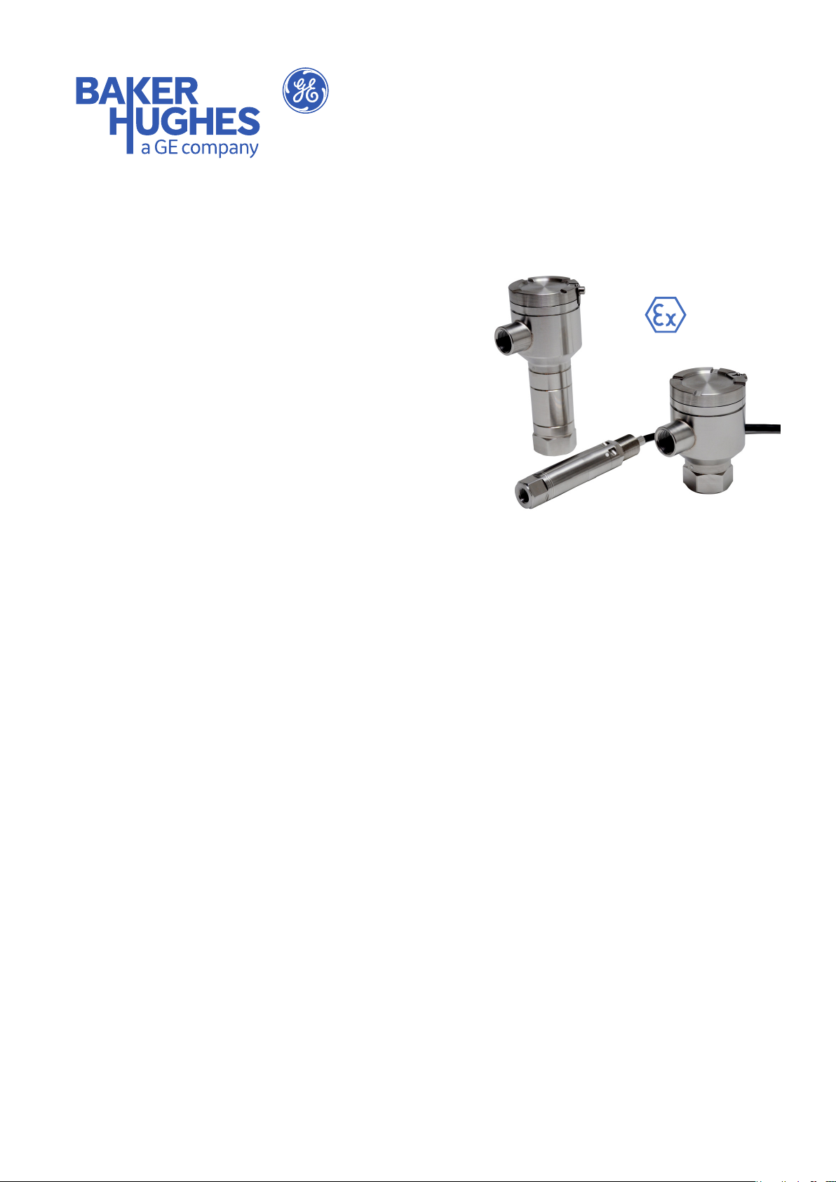
UNIK 5800/5900
Flameproof/Explosion-Proof
Pressure Sensing Platform
The 5800 and 5900 are compact and rugged versions
of the high performance UNIK 5000 pressure sensing
platform oering both ameproof/ explosion-proof
or dust ignition protection by enclosure capability as
required. Intrinsic safety options are also available.
They provide a lightweight and cost eective
alternative to pressure gauges and switches in
process and in oil and gas industry applications.
High Quality
Features
• Ranges from 2 to 700 bar (30 to 10000 psi)
With 35 years of pressure measurement experience,
our eld-proven Druck silicon technology is at the
heart of the new platform, resulting in a range of
high quality, high stability pressure sensors.
Bespoke as Standard
Custom-built from standard components,
manufacturing sensors to your requirement is fast
and simple; each UNIK 5000 is a “bespoke” pressure
sensing solution, but with the short lead times and
competitive pricing you would expect from standard
products.
Expertise
We have the people and the knowledge to support
your needs for accurate and reliable product
performance; our team of experts can help you make
the right sensor selection, guiding you and providing
the help and tools you need. It is important that you
ensure that the sensor materials and performance
selected are suitable for your application.
• Accuracy to ±0.04% Full Scale (FS) Best
Straight Line (BSL)
• Stainless Steel construction
• Integrated terminal compartment with long
or short body (5900)
• Frequency response to 3.5 kHz
• High over pressure capability
• Hazardous Area certications
• mV, mA and voltage outputs
• Oil and drilling uid (mud) resistant cable
options (5800)
gemeasurement.com
Page 2

UNIK 5800/5900 Specications
Measurement
Operating Pressure Ranges
Gauge Ranges
Any zero based range from 2 to 50 bar
(30 to 725 psi)
Sealed Gauge Ranges
Any zero based range from 10 to 700 bar
(145 to 10000 psi)
Absolute Ranges
Any zero based range from 2 to 700 bar
(30 to 10000 psi)
Non Zero Based Ranges
Non zero based ranges are available. Please contact
BHGE to discuss your requirements
Over Pressure
4 × FS (up to 200 bar for ranges ≤ 50 bar and up to
1200 bar for ranges > 50 bar)
Containment Pressure
Ranges up to 50 bar (725 psi) gauge
6 x FS (200 bar (2900 psi) max)
Ranges up to 50 bar (725 psi) absolute/sealed gauge
200 bar (2900 psi)
Ranges above 50 bar (725 psi) absolute/sealed gauge
1200 bar (17400 psi)
Supply and Outputs
Electronics
Option
0 mV Passive 2.5 to 12 10 mV/V^ <2 at 10 V
1 mV Linearised 7 to 12 10 mV/V^ <3
2 mA 7 to 28** 4-20 mA <30
3 0 to 5 V 4-wire 7 to 16** 0 to 5 V <3
4 0 to 5 V 3-wire 7 to 16** 0 to 5 V* <3
5 Basic
6 0 to 10 V 4-wire 12 to 16** 0 to 10 V <3
^ with a 10 volt supply mV output sensors give 100 mV over the full
scale pressure. Output is ratiometric to the supply voltage.
*0 to 5 V 3-wire output is non true zero. At pressures below 1% of
span the output will be xed at approximately 50 mV
**32 V maximum for non-hazardous area operation
~Supply voltage is between [Maximum Output + 1V] (7 V minimum) to
16 V (32 V in non-hazardous area operation)
Description Supply
voltage
(V)
See below~ See below <3
Congurable
(3-wire)
Output Current
Consumption
(mA)
Basic Congurable (Option 5)
Any pressure signal output congurations will be
available, subject to the following limitations:
Output Specication Basic Congurable
(Option 5)
Minimum span: 4 V
Maximum span: 10 V
Maximum output limit: 11 V
Maximum zero oset: Span / 2
Output voltage range can be specied to a resolution of 0.1 V
Not true zero, the output will saturate at < 50 mV
The output will continue to respond to 110% FS. i.e. if a 0 to
10 V output is specied, the output will continue to increase
proportionally to applied pressure until at least 11 V.
Examples
Allowed Not Allowed
0 to 5 V 1 to 4 V (span too small)
0.5 to 4.5 V 4 to 11 V (oset too big)
1 to 6 V ------
1 to 11 V ------
Supply Sensitivity
±0.005% FS/Volt (voltage and current version only)
Power-Up Time
• mV, voltage and current versions: 10 ms
Insulation Resistance/Isolation
• 500 Vdc: ≥ 100 MW
• 500 Vac: ≤ 5 mA leakage current
(mV and mA versions only).
Shunt Calibration (5800 only)
Shunt calibration provides a customer accessible
connection which, when applied, causes a shift in
output of 80% FS in order to simulate applied pressure.
It is tted to the mV version as standard. Shunt
calibration is activated by connecting Shunt Cal to -ve
Supply.
Page 3

Performance Specications
There are three grades of performance specication:
Industrial, Improved and Premium
Accuracy
Voltage, Current and mV Linearised
Combined eects of non-linearity, hysteresis and
repeatability:
Industrial: ±0.2% FS BSL
Improved: ±0.1% FS BSL
Premium: ±0.04% FS BSL
mV Passive
≤
50 bar
Industrial/Improved: ±0.25% FS BSL
Premium: not available
> 50 bar
Industrial/Improved: ±0.5% FS BSL
Premium: not available
Note: For bi-directional ranges, accuracy is specied for
each direction separately
Zero Oset and Span Setting
5900 electrical connector allows access to
potentiometers that give at least ±5% FS adjustment
Factory Set To:
Product Description Industrial Improved and
Premium
Current and Voltage Versions
(5900)
Current and Voltage Versions
(5800)
mV Versions ±3.0 mV ±3.0 mV
Long Term Stability
±0.05% FS typical (±0.1% FS maximum) per year
Temperature Eects
Four compensated temperature ranges can be chosen.
Industrial Accuracy performance:
• -10 to +50 °C (14 to +122 °F): ±0.75% FS
Temperature Error Band (TEB)
• -20 to +80 °C (-4 to +176 °F): ±1.5% FS TEB
• -40 to +80 °C (-40 to +176 °F): ±2.25% FS TEB
• -40 to +125°C (-40 to +257°F): ±2.25% FS TEB
(5900 only)
Improved and Premium Accuracy performance:
• -10 to +50°C (14 to +122°F): ±0.5% FS TEB
• -20 to +80°C (-4 to +176°F): ±1.0% FS TEB
• -40 to +80°C (-40 to +176°F): ±1.5% FS TEB
• -40 to +125°C (-40 to +257°F): ±1.5% FS TEB
(5900 only)
±0.5% FS ±0.2% FS
±1.0% FS ±1.0% FS
Physical Specications
Environmental Protection
See the Electrical Connector section
Operating Temperature Range
See the Electrical Connector section
Pressure Media
Fluids compatible with Stainless Steel 316L and
Hastelloy C276
Enclosure Materials
Stainless steel (body), Viton (O-ring)*, PTFE (vent
lter), polyurethane resin (potting)**, and polyolen
(heatshrink)**. Cable sheaths as specied (see the
Electrical Connector section
*Note: 5900 only
**Note: 5800 only
Pressure Connector
For available options, see Ordering Information
Electrical Connector
Various electrical connector options oering dierent
features are available.
Model Code
5800 5 M20 Male Conduit with
5900 B M20 Female Conduit
*Note: Designed to be enclosure Type 4X, IP66 and IP67 when properly
installed with conduit tting.
**Note: Option J is supplied with an M20 male to 1/2” NPT female
conduit thread adaptor.
Note: Hazardous area approved versions may be restricted to a
reduced maximum operating temperature range – see Hazardous Area
Approvals.
Description Max Operating
No.
Polyurethane Cable
8 ½” NPT Male Conduit
with Polyurethane
Cable
M M20 Male Conduit
with RADOX® Mud
Resistant Cable
S M20 Male Conduit
with ÖLFLEX® Mud
Resistant Cable
T ½” NPT Male Conduit
with ÖLFLEX® Mud
Resistant Cable
with Terminal
Compartment
J** ½” NPT Female
Conduit with Terminal
Compartment
)
Temp Range
°C °F
-40 to
-40 to
+80
-40 to
-40 to
+80
-40 to
-40 to
+80
-40 to
-40 to
+80
-40 to
-40 to
+80
-40 to
-40 to
+100
-40 to
-40 to
+100
+176
+176
+176
+176
+176
+212
+212
IP
Zero/
Rating
Span
Adjust
66/67 N
66/67 N
66/67 N
66/67 N
66/67 N
66/67* Y
66/67* Y
Page 4

UNIK 5800/5900 Specications
Electrical Connections
Output Option (Codes)
Model Code Code/Color
5800 5 Red +ve Supply +ve Supply +ve Supply +ve Supply
8 Yellow or White - +ve Output +ve Output +ve Output
Brown - - -ve Output -ve Output
Black -ve Supply 0V Common -ve Supply -ve Supply
Orange - - - Shunt Cal
Green Case Case Case Case
Screen - - - -
M Brown +ve Supply - - -
Blue -ve Supply - - -
Black Case - - -
Screen - - - -
S
T
5900 B I/P+ +ve Supply +ve Supply +ve Supply +ve Supply
J O/P+ - +ve Output +ve Output +ve Output
1 +ve Supply - - -
2 -ve Supply - - -
Green and Yellow Case - - -
Screen - - - -
O/P- - - -ve Output -ve Output
I/P- -ve Supply 0V Common -ve Supply -ve Supply
mA
(2)
Volt 3-wire
(4 and 5)
Volt 4-wire
(3 and 6)
mV
(0 and 1)
CE Conformity
• Pressure Equipment Directive 2014/68/EU - Sound Engineering Practice
• ATEX Directive 2014/34/EU (Optional)
• EMC Directive 2014/30/EU
BS EN 61000-6-1: 2007 Susceptibility - Light Industrial
BS EN 61000-6-2: 2005 Susceptibility - Heavy Industrial (except mV versions)
BS EN 61000-6-3: 2007+A1:2011 Emissions - Light Industrial
BS EN 61000-6-4: 2007+A1:2011 Emissions - Heavy Industrial
BS EN 61326-1: 2013 Electrical Equipment for Measurement, Control and Laboratory Use
BS EN 61326-2-3: 2013 Particular requirements for pressure transducers
• RoHS Directive 2011/65/EU
Page 5

Hazardous Area Approvals (Optional)
ATEX/IECEx Flameproof or Dust Ignition Protection by Enclosure
UNIK 5800
Ex db IIC T6 Gb (-40°C ≤ Ta ≤ +63°C) (Models 585#, 588# and 58M#), (-40°C ≤ Ta ≤ +53°C) (Models 58S# and 58T#)
Ex tb IIIC T85°C Db (-40°C ≤ Ta ≤ +63°C) (Models 585#, 588# and 58M#), (-40°C ≤ Ta ≤ +53°C) (Models 58S# and 58T#)
Per certicate nos. Baseefa 12ATEX0075X & IECEx BAS 12.0047X
UNIK 5900
Ex d IIC T* Gb
Ex tb IIIC T*°C Db
T6/T85°C (-40°C ≤ Ta ≤ +70°C)
T5/T100°C (-40°C ≤ Ta ≤ +80°C)
T4/T135°C (-40°C ≤ Ta ≤ +100°C)
Per certicate nos. Baseefa 12ATEX0074X & IECEx BAS 12.0046X
ATEX/IECEx Intrinsic Safety
UNIK 5800 & 5900
Ex ia IIC T5 Ga (-40°C ≤ Ta ≤ +80°C)
Ex ia I Ma (-40°C ≤ Ta ≤ +80°C)
Per certicate nos. Baseefa 10ATEX0204X & IECEx BAS 10.0103X
FM Approvals (Canada & United States) Explosionproof/Flameproof and/or Dust Ignition Proof by Enclosure
UNIK 5800
XP CL I DIV 1 GP ABCD T6 (-40°C ≤ Ta ≤ +63°C) (Models 585# and 588#), (-40°C ≤ Ta ≤ +53°C) (Models 58S# and 58T#)
CL I ZN 1 AEx/Ex d IIC T6 (-40°C ≤ Ta ≤ +63°C) (Models 585# and 588#), (-40°C ≤ Ta ≤ +53°C) (Models 58S# and 58T#)
CL II, III DIV 1 GP EFG T6/T85°C (-40°C ≤ Ta ≤ +63°C) (Models 585# and 588#), (-40°C ≤ Ta ≤ +53°C)
(Models 58S# and 58T#)
ZN 21 AEx tb IIIC T85°C (-40°C ≤ Ta ≤ +63°C) (Models 585# and 588#), (-40°C ≤ Ta ≤ +53°C) (Models 58S# and 58T#)
Single Seal
Per FM Approvals certicate nos. FM16US0420X (United States) and FM16CA0193X (Canada)
Note: Model 585#, using a metric electrical conduit thread, is not permitted for installation in ‘Divisions’ classied
installations in Canada.
UNIK 5900
XP CL I DIV 1 GP ABCD T*
CL I ZN 1 AEx/Ex d IIC T*
CL II, III DIV 1 GP EFG T*/T*°C
ZN 21 AEx tb IIIC T*°C
T6/T85°C (-40°C ≤ Ta ≤ +70°C)
T5/T100°C (-40°C ≤ Ta ≤ +80°C)
T4/T135°C (-40°C ≤ Ta ≤ +100°C)
Single Seal
Per FM Approvals certicate nos. FM16US0420X (United States) and FM16CA0193X (Canada)
Note: Model 59B#, using a metric electrical conduit thread, is not permitted for installation in ‘Divisions’ classied
installations in Canada.
Note: Model 59J#, using a metric electrical conduit thread and supplied with a metric to NPT thread adaptor, must be
installed with the adaptor tted.
Page 6

Ordering Information (See the online conguration tool at www.unik5000.com)
(1) Select model number
Main Product Variant
PMP Amplied Pressure Transducer
PDCR mV Pressure Transducer
PTX 4-20 mA Pressure Transmitter
Product Series
5 UNIK 5000
Diameter and Material
8 25mm Stainless Steel 316L Male Conduit
9 60mm Stainless Steel 316L Female Conduit with Terminal Compartment
Electrical Connector Note 4
5 M20 Male Conduit with Polyurethane Cable (5800 only)
8 1/2” NPT Male Conduit with Polyurethane Cable (5800 only)
B M20 Female Conduit with Terminal Compartment (5900 only)
J 1/2” NPT Female Conduit with Terminal Compartment (5900 only)
M M20 Male Conduit with RADOX® Mud Resistant Cable (5800 only) Note 3
S M20 Male Conduit with ÖLFLEX® Mud Resistant Cable (5800 only) Note 3
T 1/2” NPT Male Conduit with ÖLFLEX® Mud Resistant Cable (5800 only) Note 3
Electronics Option
0 mV Passive 4-wire (PDCR) Note 1
1 mV Linearised 4-wire (PDCR)
2 4 to 20 mA 2-wire (PTX)
3 0 to 5 V 4-wire (PMP)
4 0 to 5 V 3-wire (PMP)
5 Basic congurable 3-wire (PMP)
6 0 to 10 V 4-wire (PMP)
Compensated Temperature Range
TA -10 to +50 °C (14 to +122 °F)
TB -20 to +80 °C (-4 to +176 °F)
TC -40 to +80 °C (-40 to +176 °F)
TD -40 to +125 °C (-40 to +257 °F) (5900 only)
Accuracy
A1 Industrial
A2 Improved
A3 Premium
Calibration
CA Zero/Span Data
CB Room Temperature
CC Full Thermal
Hazardous Area Approval Note 4
H0 None
H1 IECEx/ATEX Intrinsically Safe ‘ia’ Group IIC
H2 IECEx/ATEX Intrinsically Safe ‘ia’ Group I
H3 IECEx/ATEX Protected by Enclosure Group IIIC
H4 IECEx/ATEX Flameproof Group IIC
H7 FM (C & US) Dust Ignition Proof, Groups IIIC/EFG
H8 FM (C & US) Flameproof/Explosion Proof, Groups IIC/ABCD
HA IECEx/ATEX Intrinsically Safe ‘ia’ Groups I/IIC [H1 + H2]
HT IECEx/ATEX/FM (C & US) Flameproof/Explosion Proof Groups IIC/ABCD [H4 + H8]
Pressure Connector 5800 5900
PA G1/4 Female Note 2 x
PB G1/4 Male Flat End x
PC G1/4 Male 60 degree Int Cone x
PD G1/8 Male 60 degree Int Cone x
PE 1/4 NPT Female Note 2 x
PF 1/4 NPT Male x
PG 1/8 NPT Male x
PH M20x1.5 x
PJ M14x1.5 60° Internal Cone x
PK M12x1 Internal Cone x
PL 7/16-20 UNJF Male 74° External Cone x
PM G1/2 Female x
PN G1/2 Male Note 2 x x
PP 1/2 NPT Female x
PQ G1/4 Quick Connect x
PR 1/2 NPT Male Note 2 x x
PS 1/4 Swagelok Bulkhead x
PT G1/4 Male Flat Long x
PU 7/16-20 UNF Long 37 degree are tip x
PV 7/16-20 UNF Female x
PX 7/16-20 UNF Male Short Flat x
PY 3/8-24 UNJF x
PZ M10 x 1 80° Int Cone x
RA VCR Female x
RB G1/4 Male Flat with Snubber x
RC G1/4 Male Flat with Cross Bore Protection x
RD M12 x 1.0 74 degree External Cone x
RE Quick Release Male x
RF VCR Male x
RM G1/2 Female Long Version x
RN G1/2 Male Long Version x
RP 1/2 NPT Female Long Version x
RR 1/2 NPT Male Long Version x
PTX 5 8 5 2 - TA - A2 - CB - H0 - PA Typical Model Number
Page 7

Ordering Notes
Note 1: Premium Accuracy is not available on this version
Note 2: Select one of these pressure connectors for pressure ranges over 50 bar (5800 only)
Note 3: Limited to electronics option 2 only.
Note 4: Hazardous area certications are restricted by electrical connector options in accordance with the following table:
Connector
Allowed 5 8 B J M S T
H0 Y Y Y Y Y Y Y
H1 Y Y Y Y - Y Y
H2 Y Y Y Y - Y Y
H3 Y Y Y Y Y Y Y
H4 Y Y Y Y Y Y Y
H7 Y Y Y Y - Y Y
H8 Y Y Y Y - Y Y
HA Y Y Y Y - Y Y
HT Y Y Y Y - Y Y
(2) State pressure range and units: e.g., 0 to 10 bar, -5 to + 100 psi
Unit options are:
Symbol Description
bar bar
mbar millibar
psi pounds/sq. inch
Pa Pascal
hPa hectoPascal
kPa kiloPascal
MPa MegaPascal
mmH2O mm water
cmH2O cm water
mH2O metres water
inH2O inches water
ftH2O feet water
mmHg mm mercury
inHg inches mercury
kgf/cm2 kg force/sq. cm
atm atmosphere
Torr torr
(3) State Pressure reference: e.g., gauge
Reference options are:
• gauge
• absolute
• sealed gauge
(4) State cable length and units (5800 only): Minimum length 1 m (3 ft), maximum length 100 m (300 ft), integer
values only, e.g., 1 m cable
(5) State voltage output at minimum and maximum pressure (output option 5 only): Up to 1 decimal place, e.g.,
output 0.5 to 4.5 V
Typical order examples:
PTX5882-TB-A2-CA-H3-PA, 0 to 10 bar gauge, 3 m cable
PMP59B5-TC-A3-CC-H4-PM, -15 to 75 psi gauge, output 1 to 6 Volts
PDCR5881-TB-A1-CB-H0-PN, 0 to 100 bar sealed gauge, 6 ft. cable
Page 8

Mechanical Drawings
and medium pressure UNIK 5000
Dimensions shown in mm (inches)
UNIK 5900 Mechanical Drawings
UNIK 5900 Bracket
Compatible Outline Details
Available for all pressure
ranges and either G1/2 or
1/2 NPT pressure connectors
in Male or Female.
1/2 NPT Conduit
Adapter
Use to adapt the
standard M20 x 1/5
conduit connection.
38
(1.5)
36 A/F
(1.42)
26.9 A/F (1.04)
26.2 (1.03)
1/2 NPT pressure connectors
UNIK 5800 Mechanical Drawings
UNIK 5800 High Pressure
Construction Outline Details
Available for pressure ranges
greater than 50 bar and
G1/4 or 1/4 NPT female, or
G1/2 or 1/2 NPT Male
pressure connectors.
UNIK 5800 Low Pressure
Construction Outline Details
Available for pressure ranges
less than or equal to 50 bar
and can be configured for low
Series pressure connectors.
Note: Dimensions shown for
G1/4 and 1/4 NPT Female
pressure connectors only.
Refer to main document for
list of pressure connector
options - orientation not critical.
21.9 A/F
(0.86)
25
(0.98)
15
(0.59)
15.5
(0.61)
(0.98)
25
60.8
(2.39)
48 (1.89)
60
(2.36)
88.1
(3.47)
54.5
(2.15)
UNIK 5900 Miniaturized
Package Outline Details
Available for all pressure
ranges and either G1/2 or
in Male or Female
145.6
(5.73)
Tag Attachment Hole
Connection M3 x 0.6
1.2 (0.05)
External Ground
90.6
(3.57)
136.1
(5.36)
Tag Attachment Hole
1.2 (0.05)
External Ground
Connection
M3 x 0.6
80.6
(3.17)
154.5
(6.08)
116.25
(4.5)
28
(1.1)
35.2
(1.39)
11 (0.43)
92.5
(3.64)
26.1 (1.03)
M20 x 1.5 or 1/2 NPT
conduit connection
with integrated TPE
insulated and jacketed
UL AWM 20237
or oil and drilling fluid
(mud) resistant cable.
M20 x 1.5 or 1/2 NPT
conduit connection
with integrated TPE
insulated and jacketed
UL AWM 20237
or oil and drilling fluid
(mud) resistant cable.
gemeasurement.com
© 2018 Baker Hughes, a GE company – All rights reserved.
Baker Hughes reserves the right to make changes in specications and features shown herein, or discontinue the product described at any time without notice or obligation. Contact your BHGE
representative for the most current information. The Baker Hughes logo is a trade mark of Baker Hughes, a GE company. The GE Monogram is a trademark of the General Electric Company.
920-582E
 Loading...