

Dr.Mach Mach Triaflex User manual
Triaflex Ceiling, Wall, Stand Model
Dr. Mach
Lamps and Engineering
DDIIRREECCTTIIOONNSS FFOORR UUSSEE
TTrriiaafflleexx
Stand lamp _____________________________________ Order No. 3001 1012 00
Wall lamp ______________________________________ Order No. 3001 1021 00
Single ceiling lamp_______________________________ Order No. 3001 1031 25
Order No. 3001 1031 30
Ceiling lamps combinations
Emergency power lamp___________________________ Order No. 3001 1015 00
Dr. Mach GmbH u. Co., Floßmannstrasse 28, D-85560 Ebersberg
Tel.: +49 (0)8092 2093 0, Fax +49 (0)8092 2093 50
Internet: www.dr-mach.com, E-mail: info@dr-mach.de
59220002 Edition 08 14.08.2007 / Bak Page 1/24

Triaflex Ceiling, Wall, Stand Model
Dr. Mach
Lamps and Engineering
List of contents
1. Safety instructions......................................................................................Page 3
2. Operating the lamp Triaflex R86.................................................................Page 4
2.1 ON/OFF switch, light intensity adjustment............................................Page 4
2.2 Positioning............................................................................................Page 5
2.3 Lightfield adjustment (merging of lightfields)........................................Page 7
3. Cleaning .....................................................................................................Page 8
3.1 Sterilisable handle................................................................................Page 8
3.2 Lamp head, splinter protection disk......................................................Page 10
4. Maintenance...............................................................................................Page 11
4.1 Adjustments at the ceiling-/wall attachment..........................................Page 11
4.2 Adjustments at the stand......................................................................Page 12
4.3 Adjustments at the lamp head..............................................................Page 12
4.4 Changing of spare parts.......................................................................Page 13
4.4.1 Changing the halogen bulbs .......................................................Page 13
4.4.2 Changing the fuses.....................................................................Page 14
4.4.3 Changing the filter disk................................................................Page 15
4.4.4 Changing the splinter protection disk..........................................Page 15
5. Data............................................................................................................Page 16
5.1 Technical data......................................................................................Page 16
5.2 Wiring...................................................................................................Page 17
5.3 Environmental conditions .....................................................................Page 18
6. Marking .......................................................................................................Page 18
6.1 Specification of bulb.............................................................................Page 18
6.2 Specification of fuse.............................................................................Page 19
6.3 CE-mark...............................................................................................Page 19
7. Disposal......................................................................................................Page 19
8. Spare parts.................................................................................................Page 20
8.1 Lamp head ..........................................................................................Page 20
(Ceiling- /wall- /stand model, emergency power lamp)
8.2 Swivel arm – stand model ....................................................................Page 21
8.3 Spare part list.......................................................................................Page 22
59220002 Edition 08 14.08.2007 / Bak Page 2/24

Triaflex Ceiling, Wall, Stand Model
Dear customer!
Please read the safety instructions and product description carefully before working with these lights for
the first time.
Please follow the separate mounting instructions for ceiling- and wall-mounted lamps, and for fitting the
stand foot and stand tube.
Dr. Mach
Lamps and Engineering
1. Safety instructions
Please pay attention to the directions for use when handling the lamp.
Attention:
This device is not suitable for use in hazardous locations.
The lamp is classified as a Group 1 device according to the
Regulations for EEMP.
Repairs to the lamp and special installation work on the reflector or plug-in socket
should only be carried out by ourselves or a company expressly authorized by ourselves.
The manufacturer is only responsible for the safety of the lamp if repairs and alterations have been carried out by themselves or a company who can guarantee that the
safety regulations have been observed.
The manufacturer is not liable for personal or material damages if the lamp is misappropriately or incorrectly operated or misused.
Make sure that the lamp is in perfect working order before use.
59220002 Edition 08 14.08.2007 / Bak Page 3/24

Triaflex Ceiling, Wall, Stand Model
Dr. Mach
Lamps and Engineering
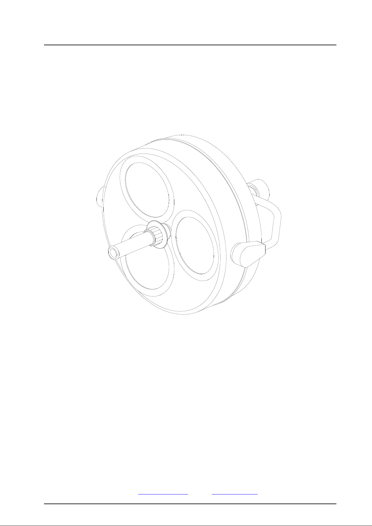
2. Operating the lamp Triaflex
The dielectric filter disk between reflector and splinter protection disk prevents a damaging heating of the
illuminated area.
The lamp may not be used without the dielectric filter disk.
2.1 ON/OFF switch,
light intensity adjustment
♦ Design for power supply 24V (fig. A)
Ceiling-/wall model,
emergency power lamp
The rocker switch 1 switches the lamp ON and OFF.
Additional to the rocker switch 1 the customer must
provide a two-pole ON/OFF switch.
Remark: In case of Triaflex R86 lamps for power
supply 24V there is no two-step light intensity adjustment.
1
♦ Design for power supply 230/120V AC
Built in toroid transformer (fig. B)
Ceiling-/wall model
The rocker switch 2 switches the lamp ON and OFF.
The rocker switch 3 adjusts the light intensity from
strong to weak.
23
ON/OFF switch
♦ Stand model (fig. C)
The lamp is equipped with two
ON/OFF switches.
The switches are positioned on the
lamp head and on the counter balance 4.
ON/OFF switch
59220002 Edition 08 14.08.2007 / Bak Page 4/24
4
Triaflex Ceiling, Wall, Stand Model
4
3
Dr. Mach
Lamps and Engineering
2.2 Positioning
♦ Ceiling-/wall model
For positioning use sterilisable handle 3.
The cardan bow 4 is used for convenient, fully car-
danic adjustment of the lamp.
It is available as extra accessory.
It is only applicable in ceiling- and wall models. For
stand models this bow is not necessary.
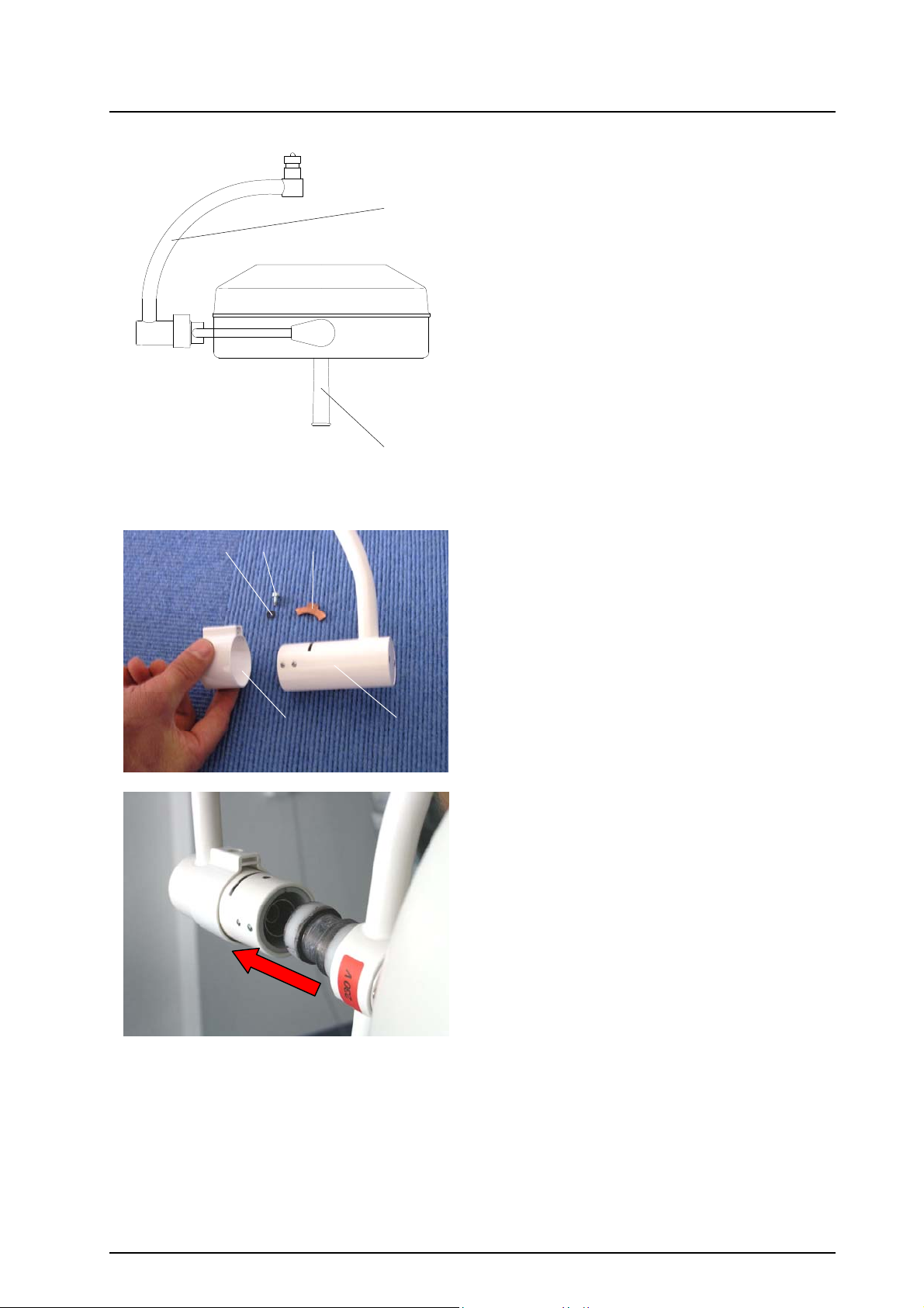
♦ Full cardanic suspension (surcharge)
Mounting the cardan bow
5
4
3
2 1
Mounting overview
Pos. 1 – Cardan bow;
Pos. 2 – Securing sleeve;
Pos. 3 – Securing segment;
Pos. 4 – Securing screw M4x10 DIN 7985;
Pos. 5 – Serrated lock washer A4,3 DIN 6798
• Slide the securing sleeve pos. 2 onto the cardan
bow pos. 1.
• Insert the coupling journal of the lamp bow into
the receptacle of the cardan bow pos. 1.
59220002 Edition 08 14.08.2007 / Bak Page 5/24
Triaflex Ceiling, Wall, Stand Model
Dr. Mach
Lamps and Engineering
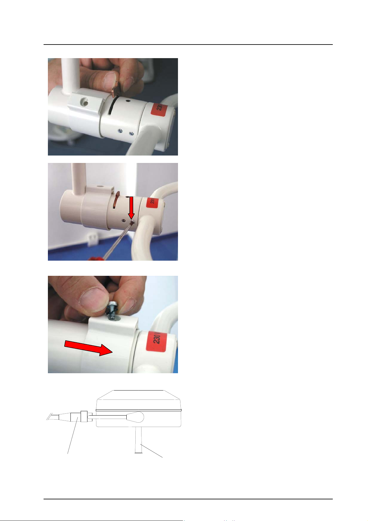
• Insert the securing segment pos. 3.
• Tighten the four brake screws very carefully
with a slotted screw driver.
• Slide the securing sleeve pos. 2 forwards
and fix it with the securing screw pos. 4 and
the serrated lock washer pos. 5.
Check the easy-going movement of the
lamp.
♦ Stand model, emergency power lamp
For positioning use sterilisable handle 3.
For stand models, the bow of the lamp body is
directly coupled to the bracket 5.
35
59220002 Edition 08 14.08.2007 / Bak Page 6/24
Triaflex Ceiling, Wall, Stand Model
3
Dr. Mach
Lamps and Engineering
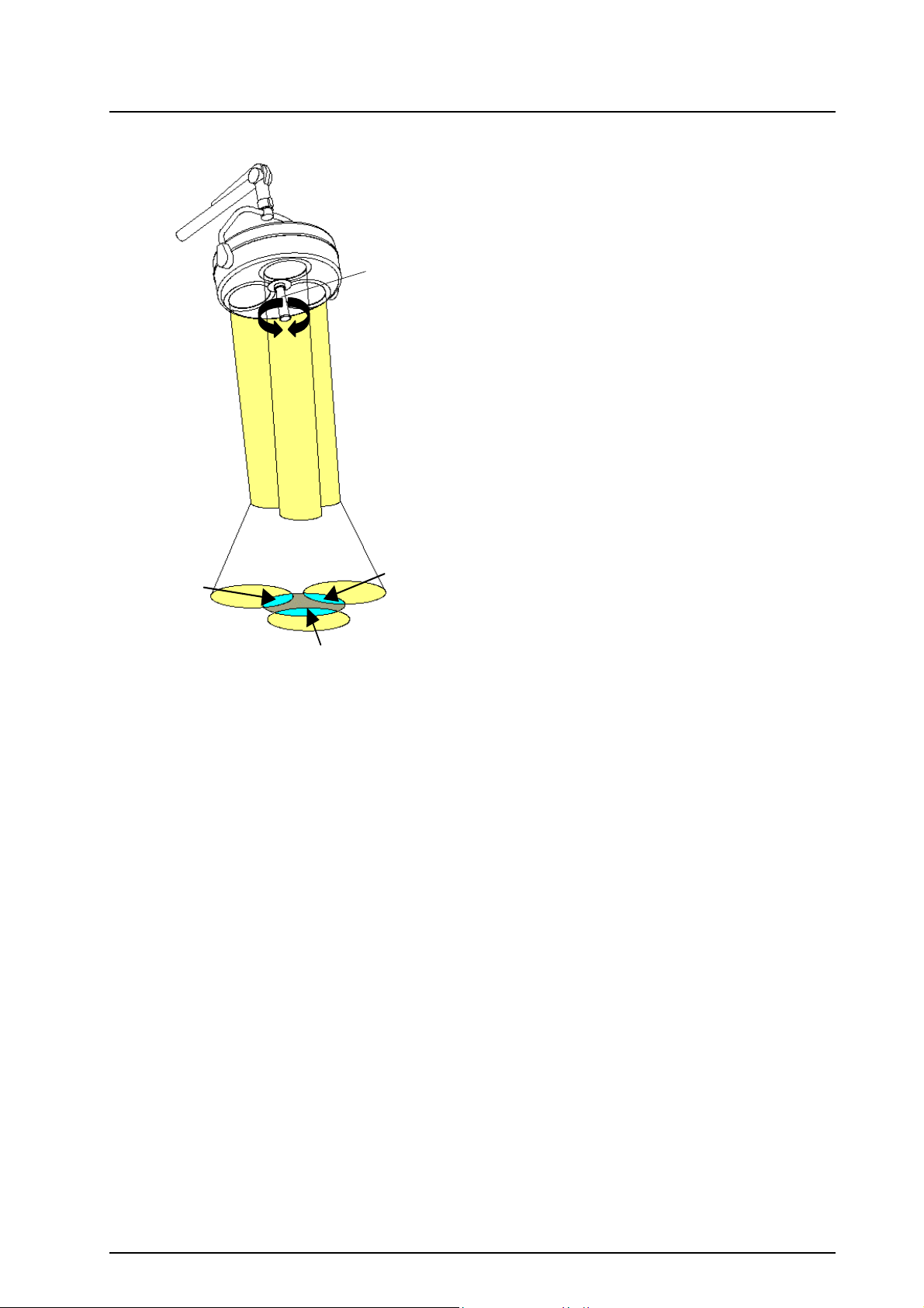
2.3 Lightfield adjustment
Merging of light fields
(available as accessory)
The lamps Triaflex R86 offer the function of lightfield adjustment (merging of lightfields) as extra
accessory.
That means, you can merge the separated lightfields
to one spot as shown in the figure.
To activate the merging of lightfields turn the sterilisable handle 3.
59220002 Edition 08 14.08.2007 / Bak Page 7/24
Triaflex Ceiling, Wall, Stand Model
Dr. Mach
Lamps and Engineering
3. Cleaning
V
1
Cleaning / disinfection and sterilisation
Basics
Efficient cleaning / disinfection is an essential requirement for effective sterilisation of the handle.
Within the scope of responsibility for the sterility of the products it should be noted that only sufficiently
validated equipment and product specific processes are used for cleaning / disinfection and that the validated parameters are complied with in every cycle.
In addition, the hospital / clinic hygiene regulations must be observed.
Cleaning / disinfection
Cleaning and disinfection must be carried out immediately after use.
A mechanised process (disinfector) should be used for cleaning / disinfection. The efficiency of the process used must be recognised and validated in principle (e.g. listed under disinfectants and disinfection
procedures tested and recognised by Robert-Koch-Institute / DGHM ).
When using other procedures (e.g. a manual procedure), proof and process efficiency in principle must
be provided within the scope of validation.
Proof in principle of the suitability of the handles for efficient cleaning / disinfection was provided using a
cyclic cleaning system (Netsch-Bellmed T-600-IUDT/AN, programme 2 for small parts; code B).
It is not allowed to use agents / disinfectants, which contain the following substances, as these may
cause changes in the material:
- High-concentration organic and inorganic acids
- Chlorinated hydrocarbons
- 2-ethoxyethanol
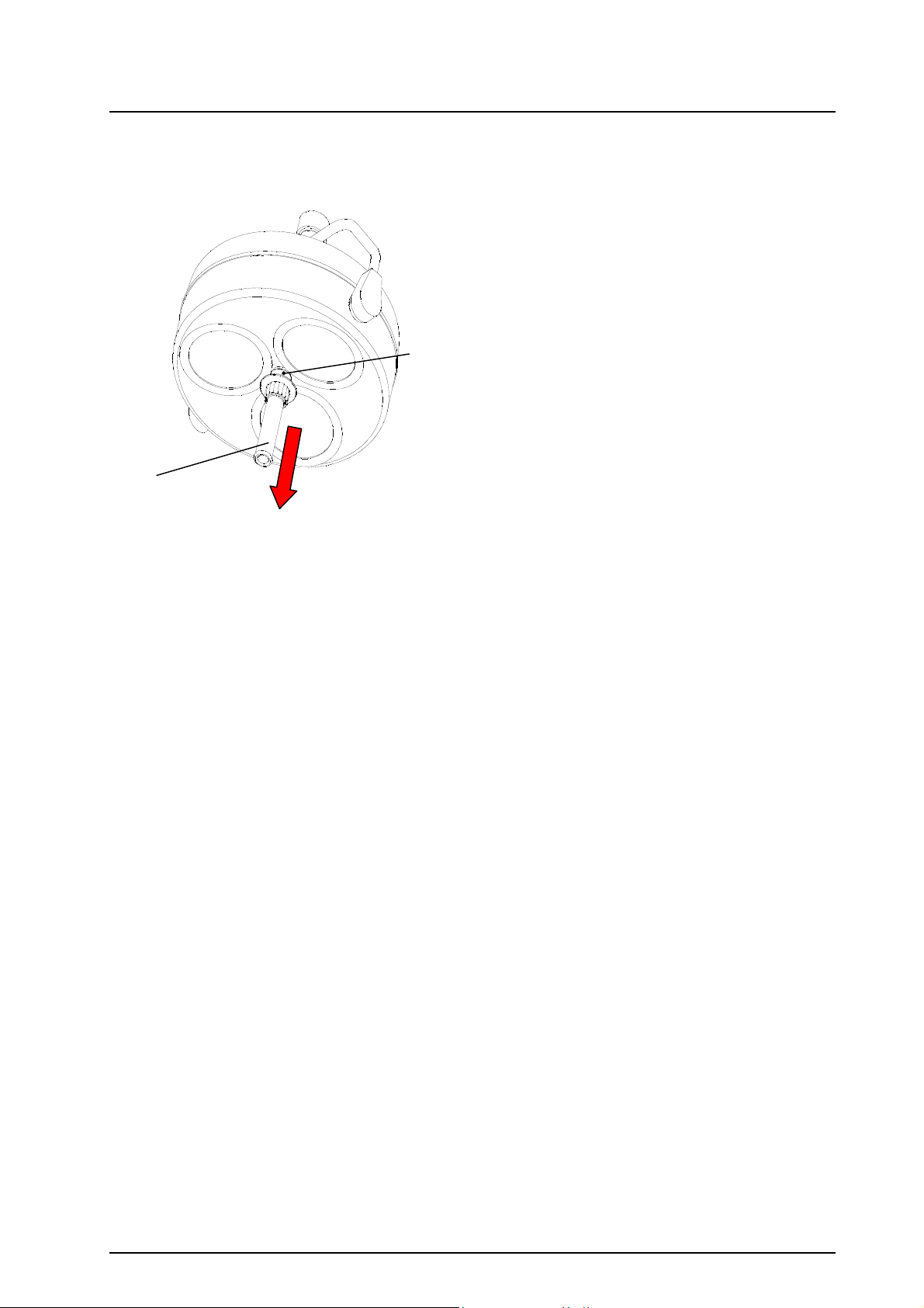
3.1 Sterilisable handle
At delivery the lamp is equipped with the handle
sleeve 1. The handle sleeve is removable and ster-
ilisable. Before using the first time and before every
use the handle sleeve must be cleaned, disinfected
and sterilised.
The handle sleeve must be removed for sterilisation:
• To remove press the lock V and pull off the ster-
ilisable handle sleeve 1 while keeping the lock
pressed.
• To attach, push on and slightly twist the handle
until the lock V engages securely.
Handles often become unsterile during an OP; therefore always keep additional handles available for
exchange.
59220002 Edition 08 14.08.2007 / Bak Page 8/24
 Loading...