


 Loading...
Ceiling and wall attachment |
Dr. Mach |
|
Lamps and Engineering |
MOUNTING INSTRUCTIONS
Ceiling attachment Wall attachment
Applies to: |
Soloflex |
|
Triaflex |
|
Trigenflex |
|
Quintaflex |
|
Mach 120 |
|
Mach 130 |
|
Mach M3 |
|
Mach M5 |
|
Mach 380 |
|
Mach 400 |
|
Mach 500 |
|
Tool and instrument trays |
Dr. Mach GmbH u. Co., Flossmannstrasse 28, D-85560 Ebersberg
Tel.: +49 (0)8092 2093 0, Fax +49 (0)8092 2093 50
Internet: www.dr-mach.com, E-mail: info@dr-mach.de
59500001 Edition 06 11.03.2003 / Bak Page 1/48

Ceiling and wall attachment |
Dr. Mach |
|
Lamps and Engineering |
These mounting instructions must be kept together with the lamp’s operating instructions for reference.
General instructions
All Dr. Mach lamps are supplied with a flange with a graduated circle diameter 270mm and six bores diameter 15mm. The flange supports the vertical suspension tube. It is attached to the solid ceiling by means of a ceiling anchorage ring.
Remark: The ceiling anchorage ring has to be ordered separately!
The ceiling anchorage ring has six precisely positioned threaded bolts M12. It makes it possible to fasten and adjust the lamp without causing dust or dirt after all building work has been completed. The use of a ceiling anchorage ring is necessary in all cases of ceiling attachments.
During mounting, take care to ensure that neither the flange nor the attachment elements are in contact with reinforcement components of the solid ceiling.
In view of the slight weight of the Dr. Mach lamps, it is not fundamentally necessary to drill through the ceiling and use a counter-plate. Ceiling anchorage rings can be attached without any problems to ceilings in the concrete strength class greater than or equal to B25, using safety dowels M8.
Depending on the stability of the location, it may be necessary to use a counter-plate for the wall attachment.
The forces arising when the widely extending articulated arms tilt, do make it necessary to drill very carefully with a certified hammer drill, paying close attention to the drilling tolerances.
The suspension tube of the lamp or lamp combination must be adjusted vertically to prevent the lamp body from moving. For this purpose the M12 counter nuts on the attaching bolts must be adjusted accordingly.
In case of false ceilings, the suspension tubes for all lamps can be mounted directly through to the solid ceiling. The opening required for this purpose can be closed once the work has been completed, using the canopy diameter 450mm or a covering plate.
When using an intermediate flange (preferably for spaces exceeding 400mm and for room heights exceeding 4050mm), the length of the intermediate flange is to be measured to the lower edge of the false ceiling.
Also in this case a ceiling anchorage ring has to be used for fixation.
59500001 |
Edition 06 |
11.03.2003 / Bak Page 2/48 |
Ceiling and wall attachment |
|
Dr. Mach |
|
|
|
|
Lamps and Engineering |
|
List of contents |
|
|
1. Mounting layout ceiling attachment .......................................................................... |
|
Page 6 |
|
2. Ceiling attachment.................................................................................................... |
|
Page 7 |
|
2.1 |
Preparatory work on the ceiling ......................................................................... |
|
Page 7 |
|
2.1.1 Setting the safety dowels .......................................................................... |
|
Page 7 |
|
2.1.2 Mounting the ceiling anchorage ring |
|
|
|
to the solid ceiling ...................................................................................... |
|
Page 7 |
2.2 |
Pre-mounting of the ceiling flange and suspension tube ................................... |
Page 8 |
|
|
2.2.1 Aluminium cast flange and suspension tube 50mm.............................. |
Page 8 |
|
|
2.2.2 Flange tube 70mm and suspension tube 50mm ............................... |
Page 9 |
|
|
2.2.3 Light-weighted central axis |
|
|
|
(connection which can turn through 360°) ................................................. |
Page 10 |
|
|
2.2.4 Ceiling attachments and room heights...................................................... |
Page 11 |
|
2.3 |
Mounting the flange and suspension tube to the ceiling.................................... |
Page 13 |
|
3. Mounting layout wall attachment .............................................................................. |
|
Page 15 |
|
4. Wall attachment........................................................................................................ |
|
Page 16 |
|
4.1 |
Preparatory work on the wall ............................................................................. |
|
Page 16 |
4.2 |
Mounting the wall bearing.................................................................................. |
|
Page 17 |
|
4.2.1 Wall attachment, room heights.................................................................. |
|
Page 18 |
4.3 |
Installing the extension arm stop (surcharge).................................................... |
Page 19 |
|
5. Electrical connection ................................................................................................ |
|
Page 20 |
|
5.1 |
Preparing the electrical connection.................................................................... |
|
Page 21 |
5.2 |
Electrical connection for lamps with external transformer ................................. |
Page 21 |
|
|
5.2.1 Ceiling lamps with external transformer .................................................... |
Page 21 |
|
|
5.2.2 Wall lamps with external transformer ........................................................ |
Page 22 |
|
|
5.2.3 Lamps with regulating transformer............................................................ |
Page 23 |
|
5.3 |
Wiring diagrams................................................................................................. |
|
Page 24 |
6. Mounting the articulated arms .................................................................................. |
|
Page 25 |
|
6.1 |
Ceiling attachment............................................................................................. |
|
Page 25 |
|
6.1.1 Mounting the extension arm...................................................................... |
|
Page 25 |
|
6.1.2 Removing the lateral covering plates ........................................................ |
Page 25 |
|
|
6.1.3 Electrical connection ................................................................................. |
|
Page 26 |
6.2 |
Wall attachment................................................................................................. |
|
Page 27 |
6.3 |
Mounting the spring arms .................................................................................. |
|
Page 27 |
|
6.3.1 Mounting the standard spring arm ............................................................ |
Page 27 |
|
|
6.3.2 Mounting the Space spring arm ................................................................ |
Page 28 |
|
|
6.3.3 Mounting the central spring arm................................................................ |
Page 29 |
|
7. Mounting the lamp / the end device ......................................................................... |
|
Page 30 |
|
7.1 |
Mounting at the standard spring arm ................................................................. |
Page 30 |
|
7.2 |
Mounting at the Space spring arm..................................................................... |
|
Page 32 |
7.3 |
Mounting at the central spring arm .................................................................... |
|
Page 33 |
8. Adjusting the mobility ............................................................................................... |
|
Page 35 |
|
8.1 |
Adjusting the mobility at the ceiling attachment................................................. |
Page 35 |
|
8.2 |
Adjusting the spring force .................................................................................. |
|
Page 36 |
|
8.2.1 Standard-spring arm ................................................................................. |
|
Page 36 |
|
8.2.2 Space spring arm ...................................................................................... |
|
Page 37 |
|
8.2.3 Central spring arm..................................................................................... |
|
Page 37 |
|
|
|
|
59500001 |
Edition 06 |
11.03.2003 / Bak Page 3/48 |
|
Ceiling and wall attachment |
Dr. Mach |
|
Lamps and Engineering |
8.3 Height adjustment ............................................................................................. |
Page 39 |
8.3.1 Standard-spring arm ................................................................................. |
Page 39 |
8.3.2 Space spring arm...................................................................................... |
Page 40 |
8.3.3 Central spring arm .................................................................................... |
Page 40 |
9. Maintenance ............................................................................................................ |
Page 41 |
10. CE –mark ............................................................................................................... |
Page 41 |
11. Spare parts ............................................................................................................ |
Page 42 |
12. Spare parts list ....................................................................................................... |
Page 45 |
59500001 |
Edition 06 |
11.03.2003 / Bak Page 4/48 |

Ceiling and wall attachment |
Dr. Mach |
|
Lamps and Engineering |
Static inspection
Note:
The static (structural) inspection must be carried out before the installation of the ceiling or wall anchorage!
-The strength of the construction must be designed, checked and certified by a structural engineer.
-The respective regional construction regulations that apply must be followed.
-If a wrong hole is drilled by mistake, e.g. drilling of a reinforcement rod, the structural engineer who is responsible must be contacted, since adequate static load distribution in the ceiling may have been endangered.
Declaration of acceptance:
It is hereby certified that the supporting ceiling / wall and the ceiling anchoring / wall anchoring is safe and adequately strong.
Project: ____________________________________________________________________
____________________________________________________________________________
____________________________________________________________________________
Anchoring (please check the one that is applicable)
- with dowels authorized by construction authority
- with counter-plate
- other
Location: ____________________________________________
Signature / Stamp: (structural engineer / construction authority)
59500001 |
Edition 06 |
11.03.2003 / Bak Page 5/48 |
Ceiling and wall attachment |
Dr. Mach |
|
Lamps and Engineering |
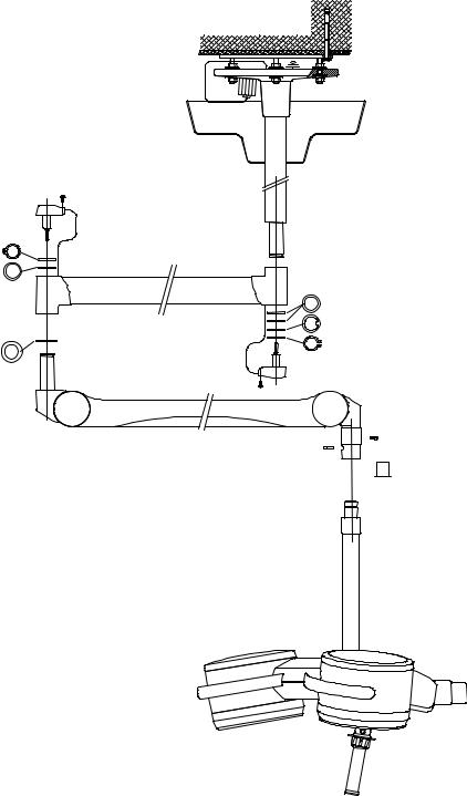
1. Mounting layout
Ceiling attachment
Ceiling anchorage ring
Intermediate flange (option)
Flange
Canopy
Suspension tube with axis
Bracket
Levelling washer (Remark!)
Gib washer 1x
Circlip 1x
Spring arm
OT -lamp
Remark:
One levelling washer is always necessary.
If the distance between bracket and spring arm is too big, use the second levelling washer.
The circlip (Seegerring) must be easy to mount and has to snap in. It should turn easily in the groove.
59500001 |
Edition 06 |
11.03.2003 / Bak Page 6/48 |

Ceiling and wall attachment |
Dr. Mach |
|
Lamps and Engineering |
2.Ceiling attachment
2.1Preparatory work on the ceiling
2.1.1 Setting the safety dowels
Attention:
Lamps, ceiling anchorage rings and intermediate flanges may only be attached to a ceiling of concrete strength class greater than or equal to B25. In case of light-weight ceiling coverings, the dowel anchor must be sunk completely into the concrete. To bridge this space use long threaded bolts for attaching the ceiling tube.
In addition, take care that neither suspension tube nor attaching elements come into contact with reinforcement components of the solid ceiling.
The lamp weight and the tilt of the long articulated arm(s) require that this work is performed meticulously. This refers particularly to the use of a certified hammer drill and to observe the drilling tolerances.
2.1.2 Mounting the ceiling anchorage ring to the solid ceiling
The scope of supply includes: 1 attachment set, consisting of:
• Six safety dowels Fischer FHA 12/50 galZn
• Mounting data Fischer
• Bore template
To attach the ceiling anchorage ring to a solid ceiling proceed as follows:
• Drill the bore holes according to the figure diameter 12mm and at least 100mm deep with a certified hammer drill, using the enclosed bore template. You can also use the ceiling anchorage ring as a template. In this case a second person may be needed to assist.
• Insert the safety dowels through the bores of the ceiling anchorage ring in such a way, that the washers lie flat to the ring.
• Tighten the screws carefully using a torque wrench (25Nm).
Light-weight ceiling panelling with a maximum thickness of 30mm can be bridged using the enclosed safety dowels. For panelling thicker than 30mm, it is necessary to remove the panelling before mounting.
59500001 |
Edition 06 |
11.03.2003 / Bak Page 7/48 |

Ceiling and wall attachment |
Dr. Mach |
|
Lamps and Engineering |
2.2 Pre-assembly of the ceiling flange and suspension tube and installing the electrical connections
The length of the suspension tube is adjusted to the required room height with a clearance height of at least 200cm under the lamp.
2.2.1 Aluminium cast flange and suspension tube 50mm
For the double models, slide the canopy (if not divided) and the ring over the corresponding suspension tube before mounting the ceiling bearing. This step is not necessary for the single models as the canopy can be slid into place after mounting the suspension to the ceiling.
Standard version
1
The diagram shows the single model and applies in the same way to the double and triple models.
• Cable or cord showing out the suspension tube is to be pushed carefully into the ceiling flange together with the suspension tube.
• Push the suspension tube upwards until the safety pin 1 can be pushed through the cross bores of the suspension tube.
• Then pull the suspension tube down until the safety pin 1 lies in recess A of the ceiling flange.
• Then secure the connection with six screws 2 and washers 3 to prevent wobbling. If not possible, turn suspension tube by 180°.
• Pull the cable or cord through the bore 4 as shown in the diagram.
Note:
The suspension tube is delivered with premounted retaining ring for the ceiling canopy.
Each connection journal is also equipped with:
• 2 spacer rings
• 1 gib ring
• 1 circlip (Seegerring)
59500001 |
Edition 06 |
11.03.2003 / Bak Page 8/48 |

Ceiling and wall attachment |
Dr. Mach |
|
Lamps and Engineering |
2.2.2 Flange tube 70mm
When necessary (in case of very high rooms or heavy lightning systems) a welded construction is used in which the ceiling flange is welded to a tube. Also for double and triple types, slide the canopy (if not divided) and the ring over the flange tube before mounting the suspension tube.
Standard version
The diagram shows the triple model and applies in the same way to the single and double models.
• Cable or cord showing out the suspension tube is to be pushed carefully into the ceiling flange together with the suspension tube.
• Push the suspension tube down until the safety bolt 1 can be pushed through bore B of the flange pipe into the cross bores of the suspension tube.
• Then pull the suspension tube down until the safety bolt lies in recess A of the ceiling flange.
• Then secure the connection with six countersunk screws M6x16 2 (tool: hexagonal socket wrench) to prevent wobbling. If not possible, turn suspension tube by 180°.
• Pull the cable or cord through the bore 4 as shown in the diagram.
• Fix the covers 5 on screws 2.
• Put the two covers on the bores B.
The table on page 9 shows the recommended distance between floor and suspension tube.
Please check this distance when mounting the lamp.
Note:
The suspension tube is delivered with premounted retaining ring for the ceiling canopy.
Each connection journal is also equipped with:
• 2 spacer rings
• 1 gib ring
• 1 circlip (Seegerring)
2 5
59500001 |
Edition 06 |
11.03.2003 / Bak Page 9/48 |

Ceiling and wall attachment |
Dr. Mach |
|
Lamps and Engineering |
2.2.3 Light weighted central axis (connection which can turn through 360°)
The pre-assembly instructions given on chapter 3.2 also apply here.
Bremsen
M8x12
DIN 915
Double model (can turn through 360°)
The suspension tubes which can turn through 360° are supplied ready mounted and wired. The length is usually already adjusted according to the room height.
Before mounting, check that the six threaded pins A of the pre-assembled connections are properly fixed.
Xplugger pin for articulated arm
(see remark at the mounting instructions for articulated arms on page 18).
Triple model (can turn through 360°)
See above.
Instructions for replacing the sliding contact set (only when required)
•Loosen cover 1 and swivel away to the side.
•Loosen the four threaded pins M8 4, so that the coupling journal 5 is loose.
•Take off safety plate 2.
•Loosen sliding contact set 3.
•Remove together coupling journal 5 and sliding contact set.
•Replace sliding contact set.
•Remount in reverse order.
Note:
This procedure is basically the same for the triple and double bracket, apart from more constricted space in the double bracket.
59500001 |
Edition 06 |
11.03.2003 / Bak Page 10/48 |
Ceiling and wall attachment |
Dr. Mach |
|
Lamps and Engineering |
2.2.4 Ceiling attachments and room heights
Ceiling attachments
Featured examples (selection)
1Single suspension tube with aluminium cast flange and ceiling anchorage ring
2Double standard axis with welded flange tube and ceiling anchorage ring
3Double light weighted central axis, can be turned through 360°, with welded flange tube and ceiling anchorage ring
4Triple light weighted central axis with welded flange tube, intermediate flange and ceiling anchorage ring
H = room height
Clearance upper edge floor – lower edge solid ceiling
h = prescribed distance upper edge floor to lower edge suspension tube as specified for the particular lamp
L = length of suspension tube respectively entire suspension device (ceiling anchorage ring + intermediate flange + suspension tube)
59500001 |
Edition 06 |
11.03.2003 / Bak Page 11/48 |
|
Ceiling and wall attachment |
Dr. Mach |
|
|
|
|
|
Lamps and Engineering |
|
|
|
Room heights H single lamps |
|
|
|
|
|
|
|
|
Lamps |
Hmin* |
Hmin** |
|
|
depending on |
depending on |
|
|
|
|
ceiling attachment |
lamp head |
|
|
Mach 120 |
2450 |
2575 |
|
|
Mach 120F |
2450 |
2575 |
|
|
Soloflex |
2450 |
2570 |
|
|
Soloflex with handle sleeve |
2450 |
2630 |
|
|
Mach 130 |
2450 |
2625 |
|
|
Mach 130 -ster. handle sleeve |
2450 |
2625 |
|
|
Triaflex |
2450 |
2580 |
|
|
Triaflex with cardan bow |
2450 |
2630 |
|
|
Trigenflex |
2450 |
2760 |
|
|
Quintaflex |
2450 |
2825 |
|
|
Mach M3 |
2450 |
2862 |
|
|
Mach 380 |
2450 |
2862 |
|
|
Mach 400 |
2450 |
2897 |
|
|
Mach 500 |
2450 |
2867 |
|
|
Tool and instrument trays |
2450 |
2680 |
|
*Min. room height in the case of ceiling attachment with shortest suspension tube (180mm)
**Min. room height in case of clearance height of 2000mm under the handle of the lamp
Room heights H single lamps – low room height
Lamps |
Hmin* |
|
depending on ceiling attachment |
||
|
||
Soloflex with turned joint |
2450 |
|
Triaflex with turned joint |
2450 |
|
Trigenflex with fully cardanic joint |
2450 |
|
Trigenflex with central spring arm |
2450 |
|
Quintaflex with central spring arm |
2450 |
|
Mach M3 with central spring arm |
2450 |
|
Mach 380 with central spring arm |
2450 |
|
Mach 400 with Space-arm |
2520 |
|
Mach 500 with Space-arm |
2520 |
*Min. room height in the case of ceiling attachment with shortest suspension tube (180mm)
59500001 |
Edition 06 |
11.03.2003 / Bak Page 12/48 |

Ceiling and wall attachment |
Dr. Mach |
|
Lamps and Engineering |
2.3 Mounting the flange and the suspension tube to the ceiling
Before mounting the flange and the suspension tube, assembly work on the ceiling (setting the dowels or mounting the ceiling anchorage ring and possibly mounting the intermediate flange) must be completed and all pre-assembly work finished.
Type with ceiling anchorage ring
• Screw three nuts B (each 120°) to the plate of the ceiling anchorage ring, holding the other three nuts 0,5cm away from the plate, unscrew nuts A.
• Position six washers C and six insulating washers D on the flange.
• Position the flange with suspension tube on the threaded bolts and adjust it to the required height using three nuts A and washers C, insulating washers D, and retaining washers E (each 120°).
Note: Washers C, insulating washers D and retaining washers E must be put on the flange in the same order as shown in the figure.
• The three-point mounting allows a simple vertical adjustment of the suspension tube.
Vertical adjustment is very important and must be carried out with great care.
If the flange with suspension tube is not in the correct vertical setting, the support arms of the lamp do not remain precisely in the proper position, they could turn away and would therefore require excessive braking.
• Then position from above all six nuts B gently against the flange.
• Screw on the remaining three nuts A with washers C, insulating washers D and retaining washers E and tighten all six nuts equally cross-wise with a torque wrench (25 Nm).
Note: Washers C, insulating washers D and retaining washers E must be put on the flange in the same order as shown in the figure.
• Verify balance with a spirit-level.
59500001 |
Edition 06 |
11.03.2003 / Bak Page 13/48 |

Ceiling and wall attachment |
Dr. Mach |
|
Lamps and Engineering |
Type with ceiling anchorage ring and intermediate flange
• Screw three nuts G (each 120°) to the plate of the ceiling anchorage ring, the other three 1cm away from the plate, unscrew nuts F.
• Position the intermediate flange on the threaded bolts and adjust it to the required height using three nuts F and washers H.
• Then position all six nuts G gently against the intermediate flange from above.
• Screw on the remaining three nuts F with washers H and tighten all six nuts equally cross-wise with a torque wrench (25 Nm).
• Verify balance with a spirit-level.
For mounting the flange to the intermediate flange proceed as described at the design with ceiling anchorage ring.
59500001 |
Edition 06 |
11.03.2003 / Bak Page 14/48 |

Ceiling and wall attachment |
Dr. Mach |
|
Lamps and Engineering |
3. Mounting layout
Wall attachment
Bracket |
Circlip |
|
Levelling washer (Remark!) |
Levelling washer
Wall bearing
Spring arm
OT -lamp
Remark:
One levelling washer is always necessary.
If the distance between wall bracket and spring arm is too big, use the second levelling washer.
The circlip (Seegerring) must be easy to mount and has to snap in. It should turn easily in the groove.
59500001 |
Edition 06 |
11.03.2003 / Bak Page 15/48 |
Loading...