

Page 1
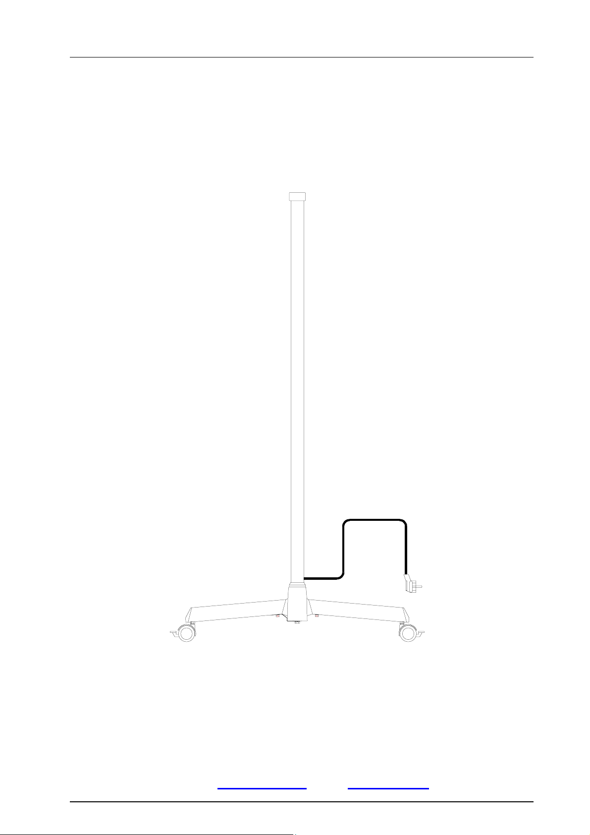
Stand foot
Mounting instructions Directions for use
STAND FOOT - STAND TUBE
Dr. Mach
Lamps and Engineering
Stand lamps:
Dr. Mach GmbH u. Co., Flossmannstrasse 28, D-85560 Ebersberg
Tel.: +49 (0)8092 2093 0, Fax +49 (0)8092 2093 50
Internet: www.dr-mach.com
Mounting instructions / Directions for use Edition 04 29.04.2005 / Bak Page 1/16
, E-mail: [email protected]
Mach 130 / Mach 130F
Soloflex
Triaflex / Triaflex R96
Trigenflex / Trigenflex R96
Page 2

Stand foot
Dr. Mach
Lamps and Engineering
List of contents
1. Safety instructions ....................................................................................Page 3
2. Installation summary - stand lamps ..........................................................Page 4
3. Overview table ..........................................................................................Page 5
Stand foot, stand tube, swivel arm
4. Mounting instructions................................................................................Page 6
4.1 Mounting the stand foot ......................................................................Page 6
4.1.1 Mounting the five-foot base .........................................................Page 6
4.1.2 Mounting the stand tube to the stand foot ...................................Page 7
4.2 Mounting the swivel arm/short bracket ...............................................Page 8
and the lamp head
4.2.1 Mounting the swivel arm/short bracket ........................................Page 8
to the stand tube
4.2.2 Mounting the lamp head to the swivel arm ..................................Page 9
5. Directions for use......................................................................................Page 10
5.1 Stand foot ...........................................................................................Page 10
5.2 Stand tube ..........................................................................................Page 10
5.3 Swivel arm ..........................................................................................Page 11
6. Cleaning....................................................................................................Page 12
7. Maintenance .............................................................................................Page 12
8. Data ..........................................................................................................Page 13
9. Disposal ....................................................................................................Page 13
10. Spare parts .............................................................................................Page 14
10.1 Spare parts - stand foot ....................................................................Page 14
10.2 Spare parts - stand tube type 1-4 .....................................................Page 15
Mounting instructions / Directions for use Edition 04 29.04.2005 / Bak Page 2/16
Page 3

Stand foot
Dr. Mach
Lamps and Engineering
1. Safety instructions
The stand foot may not be connected to the mains until it has been fully assembled and installed.
The manufacturer is only responsible for operational safety of the stand foot when repairs and
modifications are carried out by his own staff or by persons who guarantee compliance with
the safety regulations.
The manufacturer is not responsible for damage to persons or property caused by incorrect or
improper use, or when used for incorrect purposes.
General information
These installation instructions must be kept on the lamp together with the relevant
All Dr. Mach stand lamps are supplied with all
installation and connection parts and components.
For packaging reasons, the five-foot stand is
supplied in dismantled state. The stand tube is
always assembled as a unit and only needs to be
attached to the foot with the lower fastening
screw.
operating instructions for consultation at any time.
The lamp (stand tube or swivel arm) is supplied
with integrated connection lead and earthed plug.
The socket to be used for the lamp must be installed according to the requirements stipulated
by the IEC or VDE 0107.
Please check that an earthed socket is available
within the working area of the lamp.
Mounting instructions / Directions for use Edition 04 29.04.2005 / Bak Page 3/16
Page 4
Stand foot
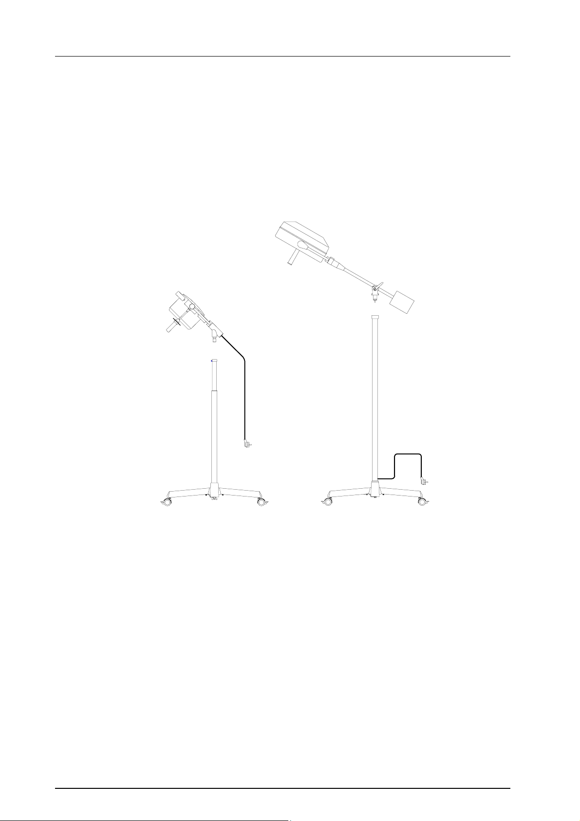
2. Installation summary - stand lamps
Type 2,3 Mach 130
Soloflex
Dr. Mach
Lamps and Engineering
Type 4 Trigenflex
Triaflex
Type 2 Type 3 and 4
Two different types of stand tubes are used:
Type 2 - stand foot with height adjustment - for examination lamps with short rigid bracket
Type 3,4 - stand foot without height adjustment - for large examination lamps and operating
lamps with swivel arm
Type 2 is not electrified; type 3 and 4 have sliding contacts for the mounted lamp at the upper end, with
the electrical lead coming out just above the foot.
Mounting instructions / Directions for use Edition 04 29.04.2005 / Bak Page 4/16
Page 5
Stand foot
Lamp type
Data
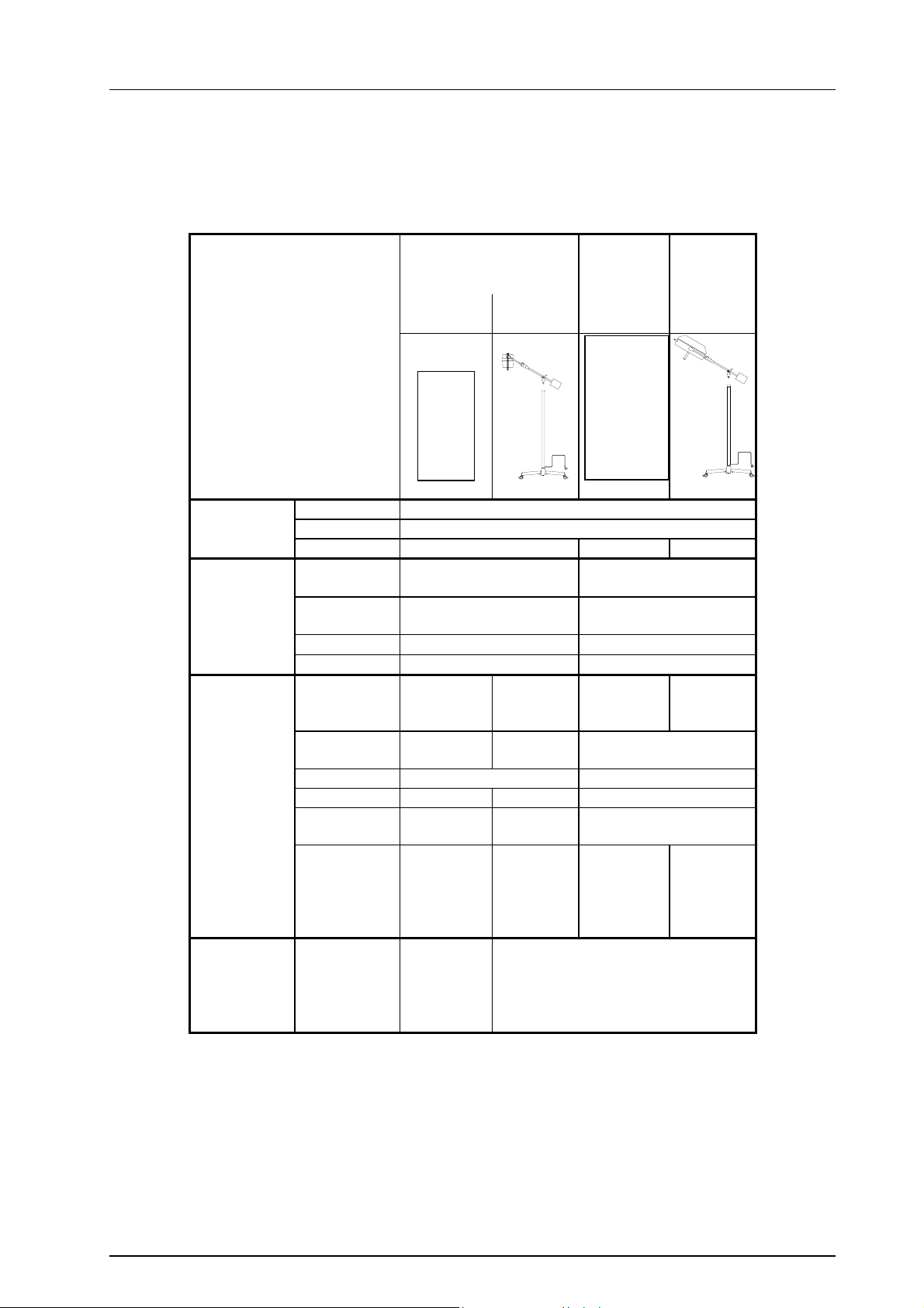
3. Overview table
Stand foot - stand tube - swivel arm
Short
bracket
Mach 130 Triaflex Trigenflex
Soloflex
Swivel
arm
Dr. Mach
Lamps and Engineering
Power
supply
Stand foot
Stand tube
Swivel arm
+
lamp head
Primary 230V AC (120V AC optional)
Secondary 24V
Transformer 50W 120W 150W
Number of 5 5
limbs
Limb 310mm 375mm
length
Roller ∅
Remark with extra weight with extra weight
Type
see point 2 Type 2 Type 3 Type 4 Type 4
Length 84cm - 128cm 148cm
approx. 138cm
Diameter 40mm 40mm
Extension yes no no
Cable no yes yes
connection
Suitable for
article no.
Lamp head
Mounting to stand
10000002 2351
10000004 2451 1561 2561
10000006
50mm 75mm
• Swivel arm to stand
• Lamp head to swivel arm
Mounting instructions / Directions for use Edition 04 29.04.2005 / Bak Page 5/16
Page 6
A
A
Stand foot
4. Mounting instructions
Extent of supply
• Stand foot - five-foot base with limbs and attachment set
• Stand tube
• Lamp head with short bracket/swivel arm
• Mounting instructions/directions for use - stand foot, stand tube
• Directions for use - lamp head
4.1 Mounting the stand foot
3
5
6
4
1
2
8
7
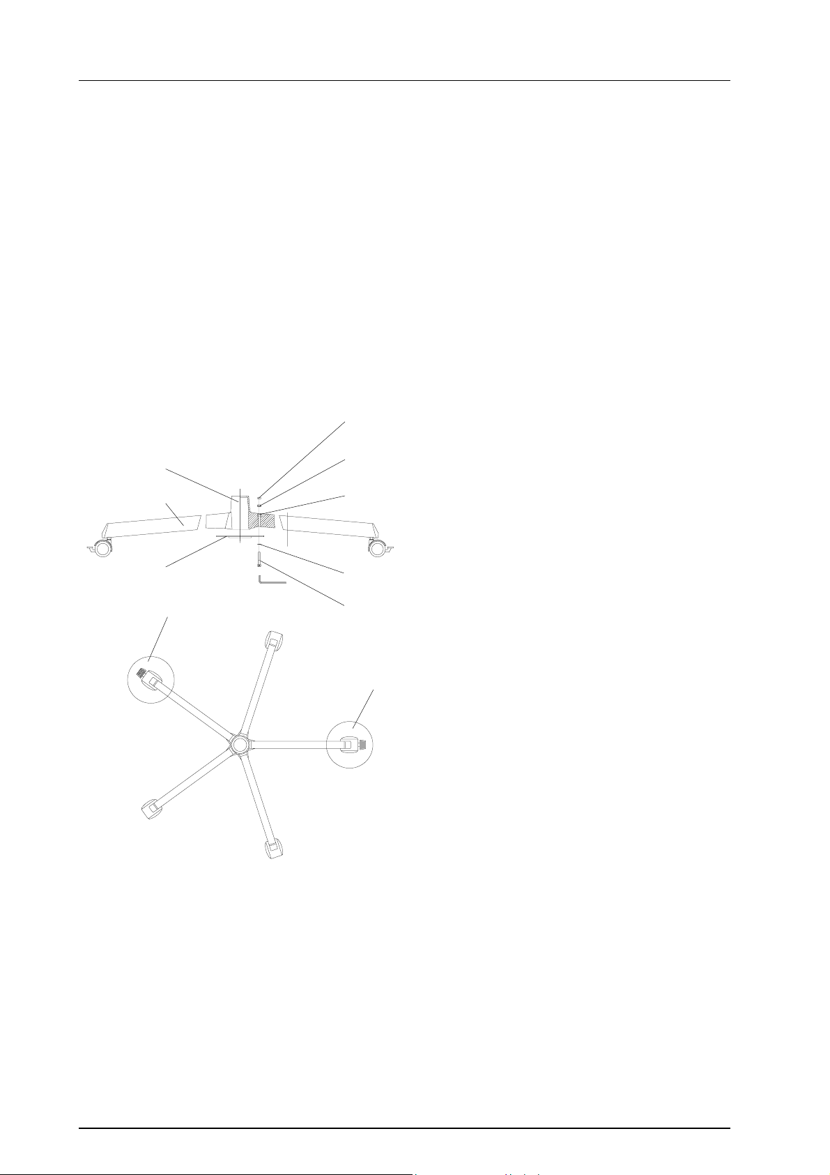
4.1.1 Mounting the five-foot base
Mounting the five-foot base is the same for all versions (type 1, 2, 3 or 4).
To mount the five-foot base proceed as follows:
• Place hexagonal nuts 1 in the recesses 2 provided in the connection braces.
• Press plastic sleeves 3 on the nuts.
• Place metal washer 4 in the recess of the middle
piece 5.
• Place the 5 profile limbs 6 on the connection
braces of the middle piece 5.
Remark: Ensure that the two rollers with
brakes are positioned opposite to each
other. (See detail A)
• Place hexagonal socket screws 7 and the spring
rings 8 into the bores as illustrated and tighten
with the hexagonal socket wrench until the aluminium profile under the screw head is shaped
in the form of a plate.
Dr. Mach
Lamps and Engineering
Mounting instructions / Directions for use Edition 04 29.04.2005 / Bak Page 6/16
Page 7
Type 2
T
T
Type 3,4
Stand foot
Dr. Mach
Lamps and Engineering
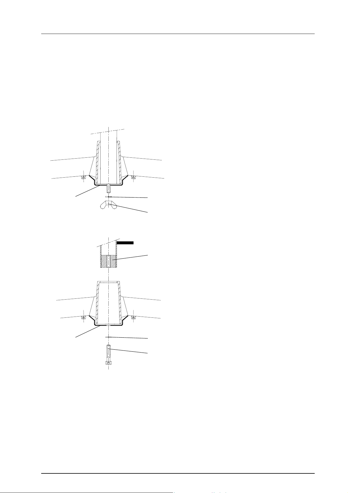
4.1.2 Mounting the stand tube to the stand foot
Two different stand tube designs are used:
a. Stand tube with single-handed adjustment (type 1 and 2)
b. Fixed stand tube for lamps with swivel arm (type 3 and 4)
Before the stand tube is placed on the foot, where necessary the earthing loop 9 on the profile limb must
be bent in such a way that the attachment screw can be placed through the bore of the earthing loop.
Stand tube type 2
♦
The stand tube is supplied with the extension
tube fully retracted. The extension tube has an
integrated spring weight balance system which
holds the mounted lamp in the precisely required position. This is secured for transport
purposes with a screw at the upper end of the
stand tube. This screw must be removed. To do
9
14
13
17
so, hold the telescope tube, remove the screw
and slowly release the tube until it reaches the
final stopper.
Insert the stand tube in the foot and attach with
the winged nut 13 and washer 14.
♦ Stand tube type 3 and 4
The stand tube is delivered with glued in
washer 17. The washer 17 has a thread for
screw 15.
Insert the stand tube in the foot, position screw
15 and washer 16 and tighten using enclosed
wrench.
9
16
15
Mounting instructions / Directions for use Edition 04 29.04.2005 / Bak Page 7/16
Page 8
Stand foot
Dr. Mach
Lamps and Engineering
4.2 Mounting the swivel arm/short bracket
and the lamp head
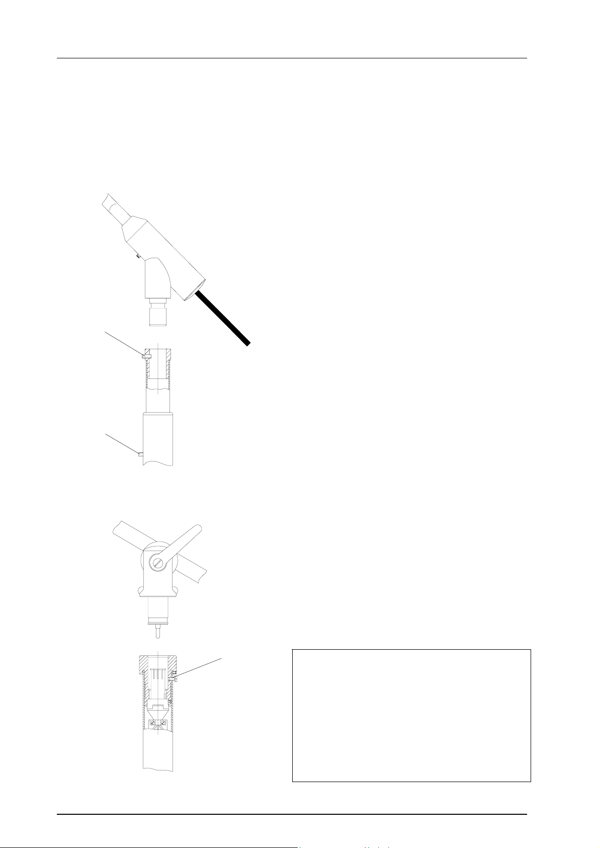
4.2.1 Mounting the swivel arm/short bracket to the stand tube
The stand tube is fitted at the upper end with a sleeve which takes the journal of the swivel arm or short
bracket.
Type 2
2
1
Type 3,4
The stand tube type 2 is delivered with fully retracted extension tube.
This position is secured for transport by screw 1, so
not to damage the integrated weight-balance system of the extension tube, which holds the lamp
head in the required position.
This screw must be removed. Hold the extensio
tube firmly while removing the screw. After the
screw has been removed, slightly let the extension
tube slip out of the stand tube, till stop.
In all models with an electrical connection routed
through the stand tube (type 3 and 4), the electrical
contact is established on inserting the journal by
means of a sliding contact with no restrictions on
the swivelling motion.
Attention: The screw 2 on the outside of the
sleeve is screwed tight after the journal has
been inserted and prevents the swivel arm or
lamp from being removed unintentionally. You
can rotate the swivel arm, but you can not remove it.
2
Caution:
Ensure that the journal of the lamp or swivel arm
has been fully inserted into the tube, so that the
safety screw engages properly in the provided
groove.
In stand tubes with integrated connection cable
(type 3 and 4) the electrical contact is not established if the journal is not properly inserted.
Mounting instructions / Directions for use Edition 04 29.04.2005 / Bak Page 8/16
Page 9
Stand foot
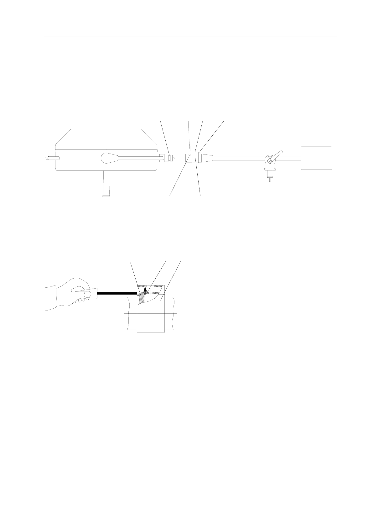
4.2.2 Mounting the lamp head to the swivel arm
(Necessary for stand type 1, 3 and 4)
Dr. Mach
Lamps and Engineering
67
58
To mount the lamp head to the swivel arm proceed
as follows:
• Loosen and remove the screw 2 and the lock
washer 3.
• Remove spring element 4 from the swivel arm
546
safety sleeve 5, using a screwdriver.
• Push safety sleeve 5 back and remove segment
6.
• Bring the swivel arm into a horizontal position an
hold it.
• Push the lamp into the swivel arm bore in such a
way that journal groove 7 is visible in slot 8.
• Insert segment 6 and push safety sleeve 5 for-
wards again as far as it goes.
• Insert the screw 2 and the lock washer 3 and
tighten.
42,3
Mounting instructions / Directions for use Edition 04 29.04.2005 / Bak Page 9/16
Page 10
A
A
Stand foot
Dr. Mach
Lamps and Engineering
5. Directions for use
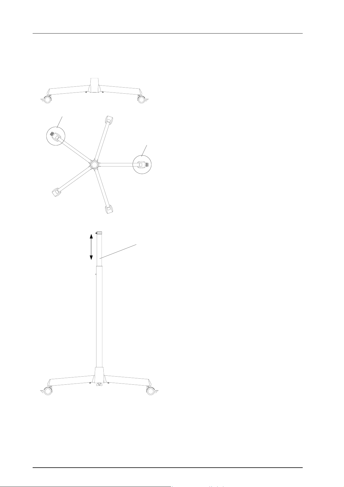
5.1 Foot
The five-foot models are equipped with two opposing braked wheels.
Set the brake by pressing the pedal on the roller
(see detail A).
Unlock by lifting the pedal again.
5.2 Stand tube
2
♦ Stand tube type 2
The stand tube can be adjusted continuously in
height and fixed in the precisely required position,
needing only one hand.
The height is adjusted simply by lifting the extension tube.
The position is automatically fixed on letting go.
Mounting instructions / Directions for use Edition 04 29.04.2005 / Bak Page 10/16
Page 11
Stand foot
constant
Dr. Mach
Lamps and Engineering
♦ Stand tube type 3 and 4
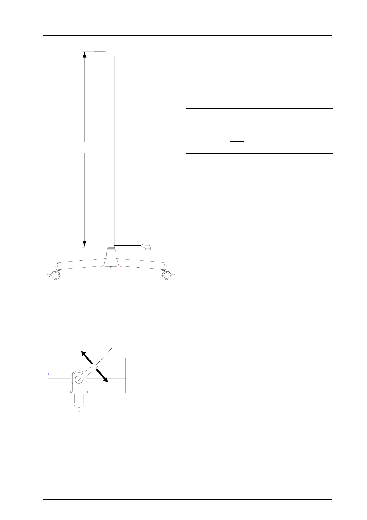
The stand tube is used to support the additional lamp
with swivel arm.
The stand tube can not be adjusted in height.
Caution:
The stand may not be connected to the
mains until after the swivel arm has been
properly inserted.
(3) 1
(2)
5.3 Swivel arm
The swivel arm with transformer as counterweight is
in balance when the lamp is inserted in position.
Adjust the moving of the swivel arm with the adjusting
lever 1:
• The swivel doesn’t hold its set position:
Turn the adjusting lever clockwise as far as necessary (2). You can fix the lamp in the required
position.
• The swivel arm moves sluggishly:
Turn the adjusting lever anti-clockwise (3), until
you can move the swivel arm easy enough.
The adjusting lever can be brought into a suitable
position by pulling it out, without changing the adjusted clamping force.
Mounting instructions / Directions for use Edition 04 29.04.2005 / Bak Page 11/16
Page 12
Stand foot
Dr. Mach
Lamps and Engineering
6. Cleaning
Alc. ≤ 20 %
The surface of the stands can be easily kept clean
by simply wiping with a damp cloth. You can use
conventional cleaning agents.
In case of disinfection only use disinfectants with
less then 20% alcohol.
Remark: For cleaning the lamp head, the dispersion lenses and splinter protection disks,
see respective instructions for use of the lamp.
7. Maintenance
Caution!
In all models with electrical connection routed through the inside of the stand tube (type 3 and 4),
the mains plug must be disconnected before performing any maintenance work.
The mounting journal and journal groove of the lamp should be lightly greased with acid-free grease
when mounting the lamp and once in a year.
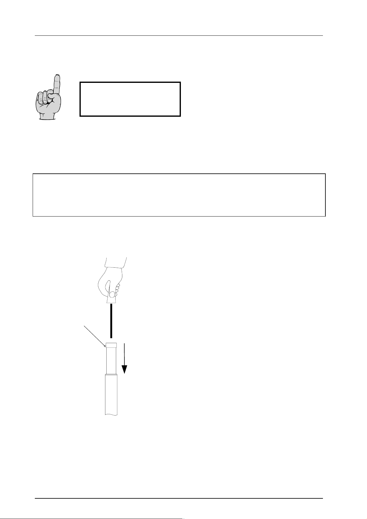
4
♦ Adjusting the spring force
(stand tube type 2)
To adjust the spring force, proceed as follows:
• Remove the lamp head.
Unscrew the threaded pin M5x10 4 in the seal
ring of the extension tube until the lamp can be
pulled out upwards.
• Remove the lamp head.
• Push the extension tube right down to the bot-
tom. In the inside of the tube you can see the
adjusting screw.
• Turn the adjusting screw with a screwdriver as
follows:
a. The lamp doesn’t hold its position and
moves downwards:
Turn the screw clockwise. The braking effect increases.
b. The lamp moves upwards sluggishly:
Turn the screw anti-clockwise. The braking effect decreases.
Mounting instructions / Directions for use Edition 04 29.04.2005 / Bak Page 12/16
Page 13
Stand foot
Dr. Mach
Lamps and Engineering
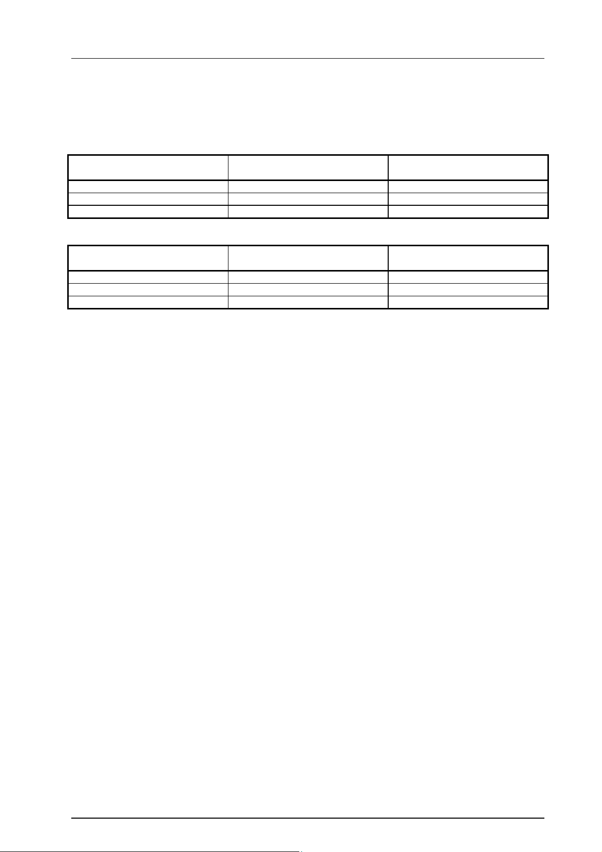
8. Data
Environmental conditions
Operation
Temperature +10°C +40°C
Relative atmospheric humidity 30% 75%
Air pressure 700 hPa 1060 hPa
Transport / storage
Temperature -10°C +50°C
Relative atmospheric humidity 20% 90%
Air pressure 700 hPa 1060 hPa
Min.
Min.
Max.
Max.
9. Disposal
The stands do not contain any danger goods.
The components of the stand should be properly disposed at the end of its shelf life.
Make sure, that the materials are carefully separated.
The components of the stand should be disposed according to the contained materials.
Mounting instructions / Directions for use Edition 04 29.04.2005 / Bak Page 13/16
Page 14
Stand foot
Dr. Mach
Lamps and Engineering
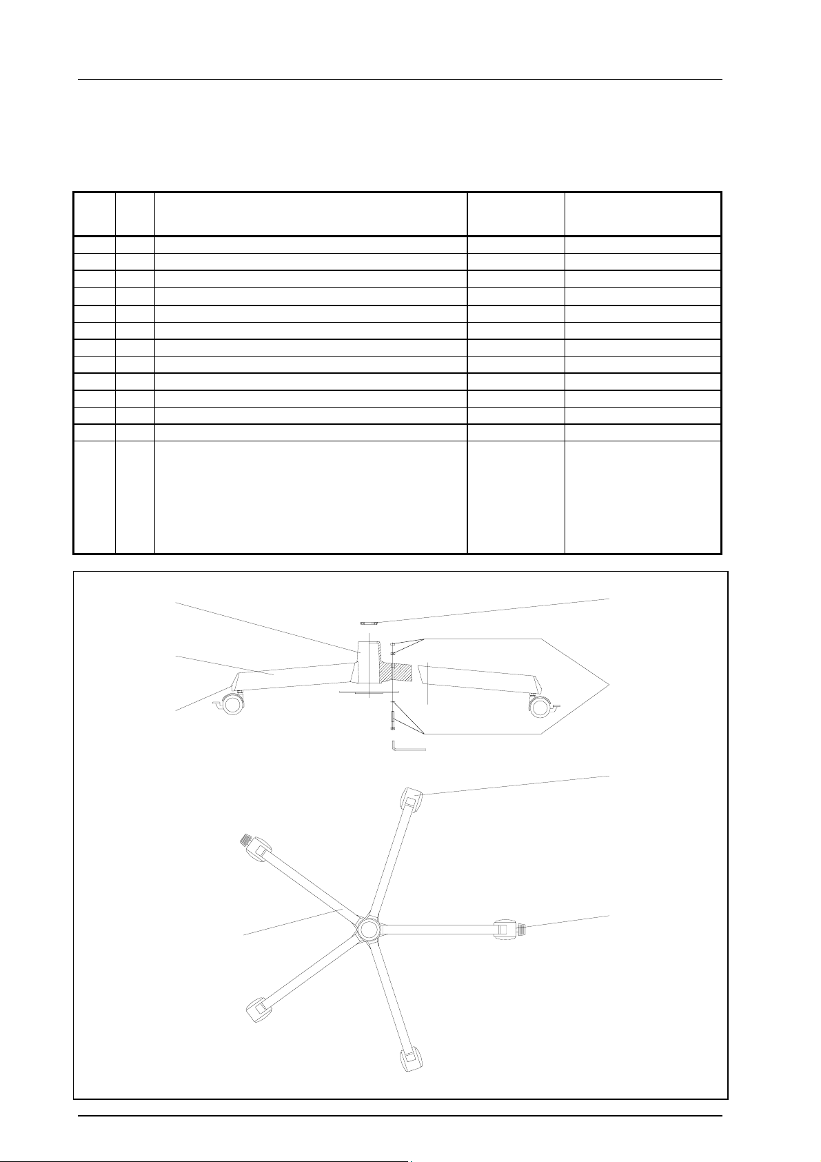
10. Spare parts
10.1 Spare parts - stand foot
Item
Qty.
01 1 Five-foot base 74905004 Mach 130, Soloflex
02 1 Five-foot base 74905005 Triaflex, Trigenflex
03 1 Middle piece for five-foot 74916001
04 1
05
06 5 Limb, length 310 mm type 2 and 3 74916003
07 5 Limb, length 350 mm type 4 74916004
08 3 Roller Ø 50 mm 74916005 for 06
09 2 Roller Ø 50 mm with brake 74916006 for 06; 2 each/ft.
10 3 Roller Ø 80 mm 74916007 for 07
11 2 Roller Ø 80 mm with brake 74916008 for 07; 2 each/ft.
12 5 End cap 74916009
13 1 Attachment set consisting of:
Bushing from ∅ 40mm to ∅ 25mm
- 1x middle cross for 5-foot base
- 5x cheese head screw DIN 912 M8x40-Zn
- 1x cheese head screw DIN 912 M8x22-Zn
- 6x lock washer J8,4 DIN 6797-Zn
- 5x nut DIN 934 M8-8-Zn
- 1x Allen key SW6
3
Name
EDVNO
74916002
74916010
74916011
65052062
65052108
65582018
65332009
67080226
Remarks
4
6,7
12
13
8,10
9,11
1,2
Mounting instructions / Directions for use Edition 04 29.04.2005 / Bak Page 14/16
Page 15
Stand foot
Dr. Mach
Lamps and Engineering
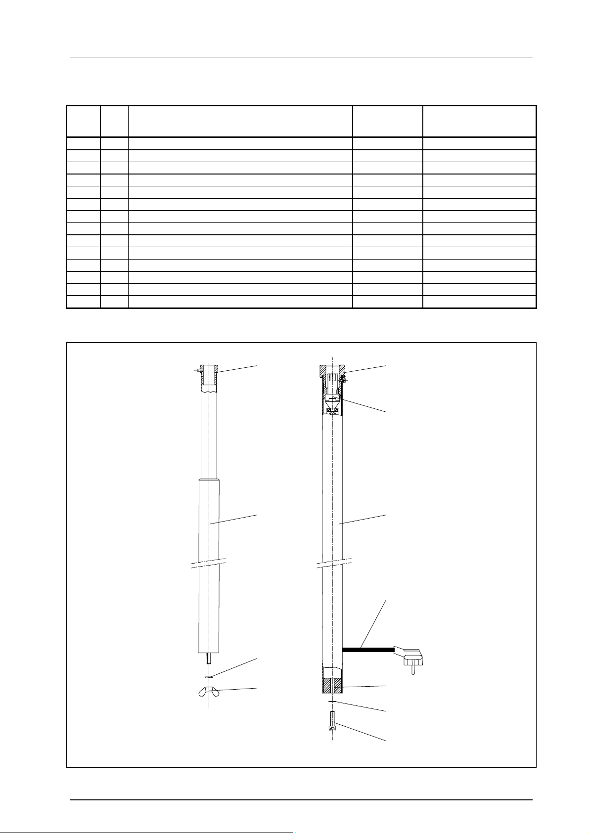
10.2 Spare parts - stand tube type 1 - 4
Item
01
02
03
04 1 Stand tube with extension type 2 52101001
05 1 Stand head 52071208
06 1 Winged nut
07 1 Stand tube with electric connection type 3 52071001 Mach 130, Soloflex
08 1 Stand tube with electric connection type 4 52071002 Triaflex, Trigenflex
09 1 Sliding contact 52071203
10 1 Stand head 52071204
11 1 Attachment screw 65062012
12 1 Spring ring
13 1 Washer 52071209
14 1 Power cord with plug (length 4 meters) 67200201
Qty.
Name
Type 2 Type 3 and 4
EDVNO
Remarks
5
4
10
9
7,8
14
12
6
13
12
11
Mounting instructions / Directions for use Edition 04 29.04.2005 / Bak Page 15/16
Page 16

Stand foot
Dr. Mach
Lamps and Engineering
Mounting instructions / Directions for use Edition 04 29.04.2005 / Bak Page 16/16
 Loading...