

Mach M5
Dr. Mach
Lamps and Engineering
Instructions for use
MACH M5
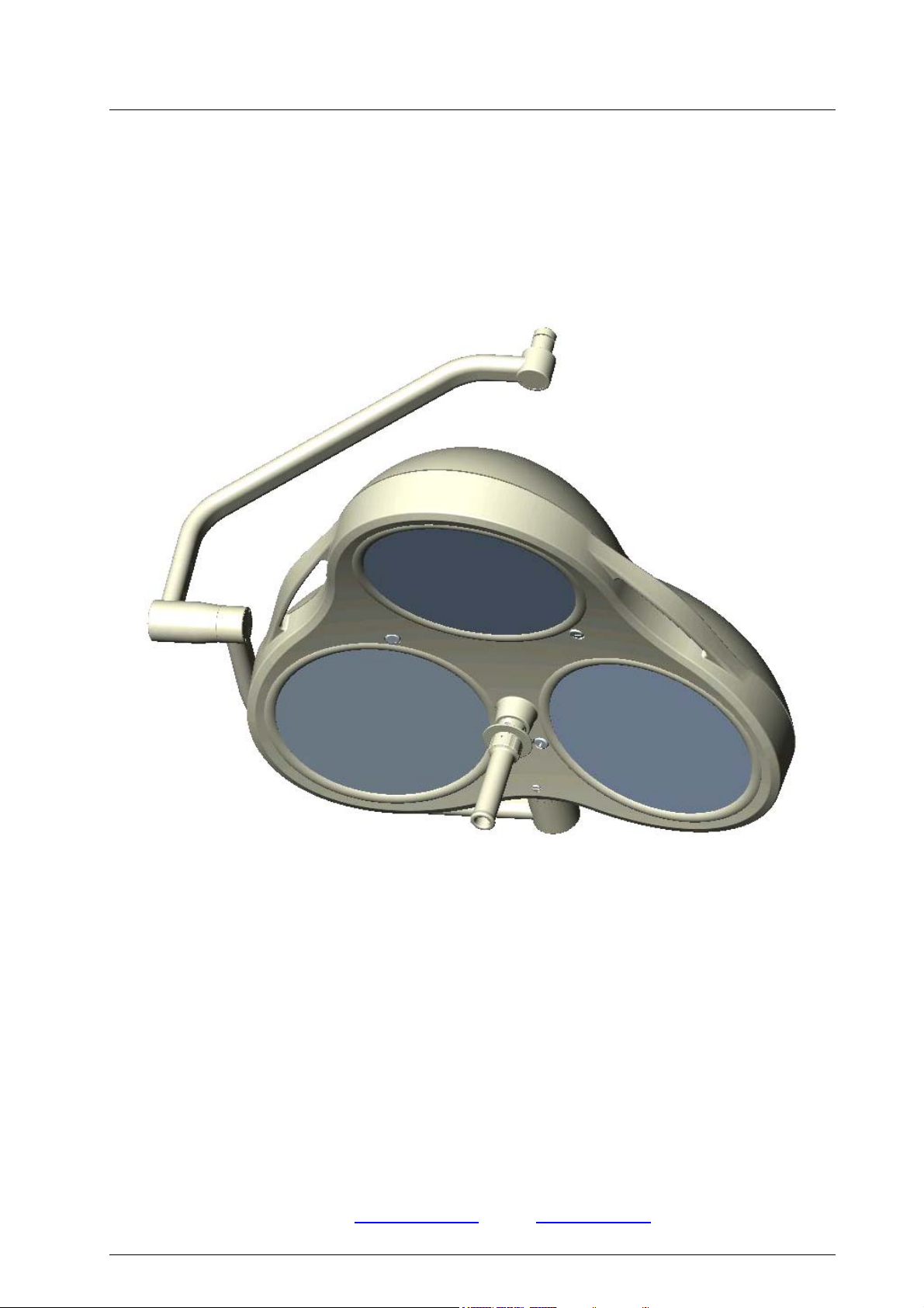
Mach M5 ceiling lamp for room heights up to 2,8m, F- / F/H / DF- / DF/H-model
Mach M5 ceiling lamp for room heights between 2,8m – 3m, F- / F/H / DF- / DF/H-model
Dr. Mach GmbH u. Co., Floßmannstrasse 28, D-85560 Ebersberg
Tel.: +49 (0)8092 2093 0, Fax +49 (0)8092 2093 50
Internet: www.dr-mach.com, E-Mail: info@dr-mach.de
59270001 Edition 06 28.09.2004 / Bak page 1/26

Mach M5
Dr. Mach
Lamps and Engineering
List of contents
1. Safety instructions ....................................................................................page 4
2. Operating the lamp MACH M5..................................................................page 5
2.1 Brief description of the lamp ...............................................................page 5
2.1.1 Merging of light fields (F-model) ..................................................page 5
2.1.2 Focusing (DF-model)...................................................................page 5
2.1.3 Light intensity control (/H-model).................................................page 5
2.2 Turning the lamp ON/OFF ..................................................................page 6
2.3 Adjusting the illuminated area by........................................................page 6
merging of light fields (for F- and F/H-models)
2.4 Adjusting the illuminated area by........................................................page 6
merging of light and focusing –
Duo Focus system (for DF- and DF/H-models)
2.5 Overview of the lamp functions...........................................................page 7
2.6 Adjusting the light intensity .................................................................page 8
2.7 Positioning ..........................................................................................page 9
3. Cleaning....................................................................................................page 10
3.1 Sterilisable handle ..............................................................................page 10
3.2 Lamp housing, dispersing lens and support system ...........................page 12
4. Maintenance .............................................................................................page 12
4.1 Adjustments at the lamp head ............................................................page 12
4.2 Changing of spare parts .....................................................................page 13
4.2.1 Changing the halogen bulbs........................................................page 13
4.2.2 Changing the filter disk ................................................................page 15
4.2.3 Changing the dispersing lens ......................................................page 17
5. Data ..........................................................................................................page 19
5.1 Technical specifications......................................................................page 19
5.2 Electrical data .....................................................................................page 20
5.3 Environmental conditions....................................................................page 20
5.4 General remarks.................................................................................page 20
6. CE-mark....................................................................................................page 21
7. Disposal ....................................................................................................page 21
8. Spare parts ...............................................................................................page 22
9. Spare parts list..........................................................................................page 24
10. Appendix: Setting the primary voltage
at the block transformer 300VA ...............................................page 25
59270001 Edition 06 28.09.2004 / Bak page 2/26

Mach M5
Dear customer!
Congratulations for acquiring our new OT-lamp MACH M5.
The MachVISION optical system provides an illuminated field with improved contrast and
excellent homogenity. Combined with the Duo-Focus feature this offers a unique possibility
for adaptation to the wound area.
With this lighting system you profit from a whole range of new developments, based on 50
years of experience in the production of operating and doctor’s lights.
The lighting system is characterised by a previously unreceivable general colour rendition
value of Ra = 96. In other words, the colours are reproduced naturally and in high con-
trast. The wound area is shown in a comfortable light.
The different reds of a wound area can now be recognised very precisely. For the doctor or
surgeon this means a considerable improvement in the recognition of details in the wound
area.
The R96 lighting system uses computer-optimised cold-light filters that reduce both the un-
wanted build-up of heat in the head area and the heat radiated on the illuminated
wound area to a minimum.
Pay attention to the special mounting instructions for ceiling lamps.
All information quoted here relates only to the illuminants. Details of ceiling or wall installation
can be found in the mounting instructions.
Dr. Mach
Lamps and Engineering
59270001 Edition 06 28.09.2004 / Bak page 3/26
Mach M5
Dr. Mach
Lamps and Engineering
1. Safety instructions
Pay attention to the instructions for use when handling the lamp.
WARNING:
This device has not been designed for use in potentially explosive areas.
According to the Medical Device Regulation the lamp is classified under class I.
Store the OT-lamp in its package for at least 24 hours in the respective room before
mounting, in order to equal temperature differences.
Please read the instructions for use carefully to make the most of your lighting
system and to avoid any damages to the device.
The lamps may only be repaired and special assembly work may only be carried
out on the reflector or sockets by ourselves or a company that has been expressly
authorised by us.
The manufacturer can only be made responsible for the safety of the lamp if repairs and alterations are carried out by the manufacturer himself or a company that
guarantees to observe the safety regulations.
The manufacturer cannot be made liable for personal or material damages if the
lamp is operated inexpediently or incorrectly or used for purposes other than
those for which it is intended.
The lamp is to be dismantled from the spring arm in reverse order to its assembly.
This may only be carried out after the spring arm has been adjusted in height at
horizontal position since the arm is under spring tension and can bounce up.
Make sure that the lamp is in perfect working order before every use.
Attention, external transformer!
The lamp works only with an external transformer 300VA.
The external transformer (Order No. 6701 0208) must be tested and validated according to IEC 60601-1.
If the external transformer is not tested and validated according to IEC 60601-1, it
is not allowed to use it with Dr. Mach OT-lamps.
59270001 Edition 06 28.09.2004 / Bak page 4/26
Mach M5
2. Operating the lamp MACH M5
2.1 Brief description of the lamp
The OT-lamp MACH M5 is available in following versions:
- Standard OT-lamp (F) with merging of light fields
- Duo-Focus OT-lamp (DF) with merging of light fields and focusing
- F- or DF- lamps with light intensity control (/H)
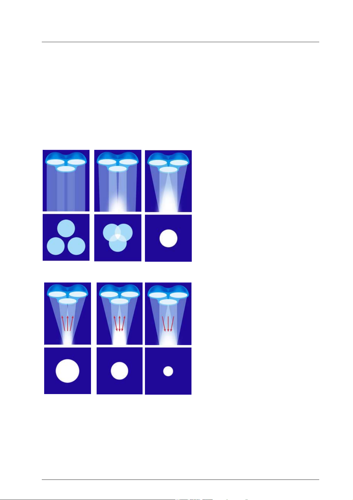
2.1.1 Merging of light fields
(F- model)
The F-model offers light field adjustment by
merging the individual light fields of each
reflector by swiveling them.
NOTE: This feature is activated by turning the
sterilisable handle.
Dr. Mach
Lamps and Engineering
2.1.2 Focusing (DF- model)
The DF-model offers a second additional facility to further adjust the illuminated field to an
extra small or extra large size, depending on
the specific requirements, by focusing
through moving the bulbs up or down.
NOTE: This feature is activated by turning the
ring at the top of the sterilisable handle.
2.1.3 Light intensity control (/H- model)
The OT-lamp models offer an optional feature, the light intensity control.
You can adjust the light intensity between 50% and 100%; according to your requirements.
59270001 Edition 06 28.09.2004 / Bak page 5/26
Mach M5
Dr. Mach
Lamps and Engineering
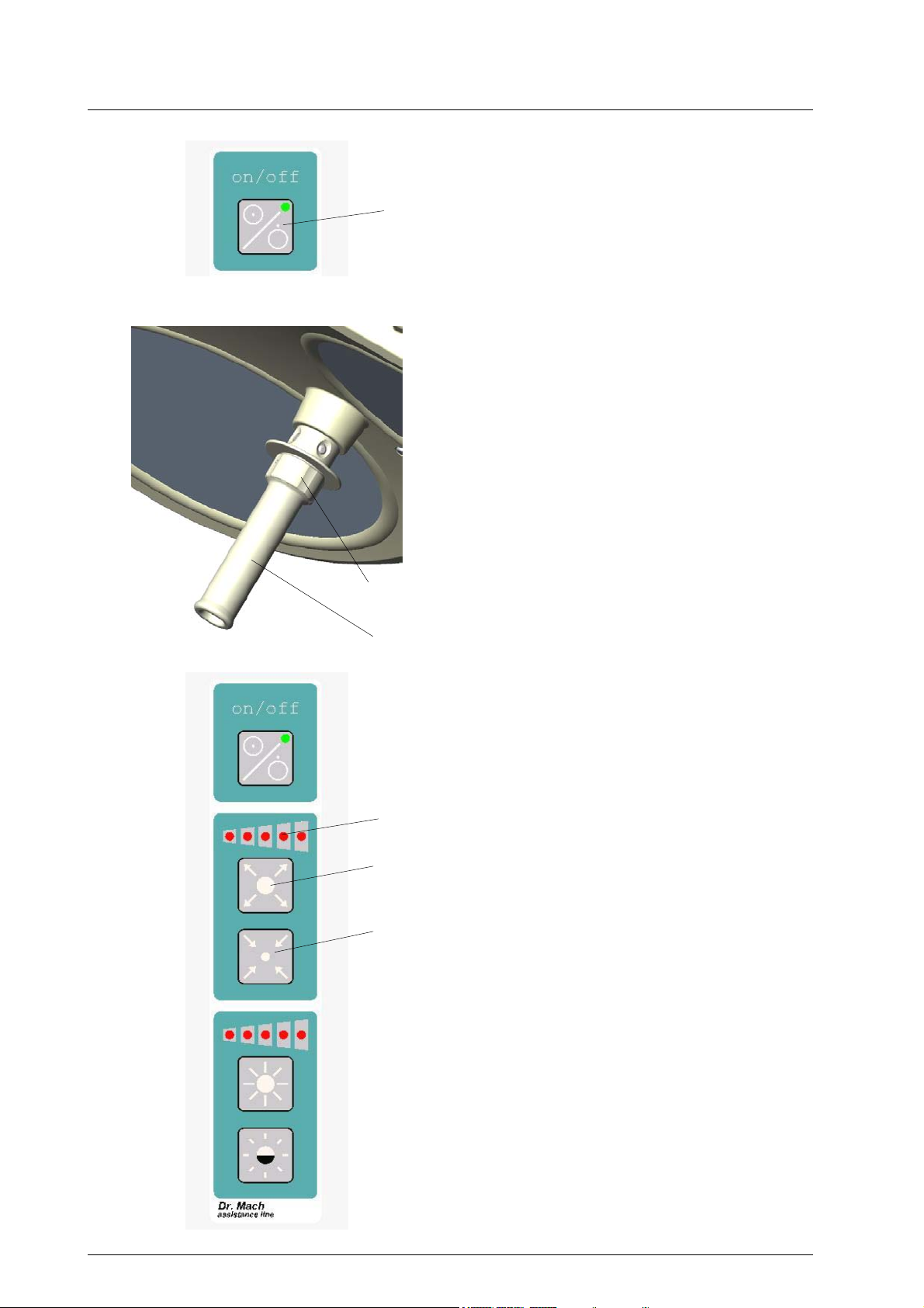
2.2 Turning the lamp ON/OFF
The F- and DF-models are switched ON/OFF at the
1
main switch of the OT or at the ON/OFF switch at the
cardan bow (if ordered).
The F/H and DF/H models are switched ON/OFF
with the touch-button 1 at the key-pad of the lamp.
2.3 Adjusting the illuminated area by
merging the light fields
(for F- and F/H-models)
All F and F/H lamp models offer the feature of “merging the light fields”. This feature is activated by turning the sterilisable handle 2.
Remark:
The ring 3 has no function here.
3
2
2.4 Adjusting the illuminated area by
merging the light fields and
focusing – Duo-Focus system
(for DF- and DF/H-models)
DF- and DF/H-models also have a “focusing” func-
tion (Duo-Focus).
The combination of merging the light fields and focus-
4
5
6
ing (Duo-Focus system) enables the ideal adjustment of the light field to the wound area in a range
from 8cm to 35cm diameter. Such a large range of
adjustment is not possible with conventional technique.
To activate the focusing function turn the adjusting
ring 3 on the handle, or – if the lamp is equipped with
a keypad at the cardan bow (for DF/H-models) –
press touch buttons 5 and 6.
Press touch button 5 to expand the focus and touch
button 6 to bundle the light to a minimum area. The
current focused diameter is shown in the LED-
display 4.
59270001 Edition 06 28.09.2004 / Bak page 6/26
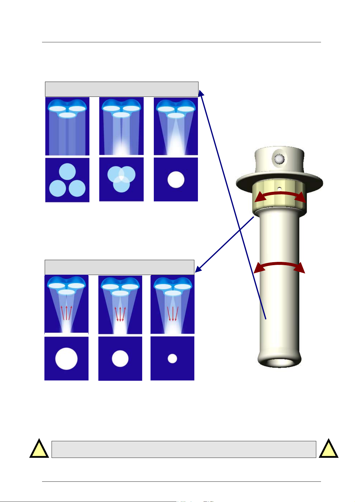
Mach M5
Merging of light fields and focusing
MERGING OF LIGHT FIELDS
2.5 Overview of the lamp functions
Dr. Mach
Lamps and Engineering
Merging the individual light fields of each reflector
is done by swivelling the reflectors. The light fields
overlap.
This feature is activated by turning the sterilizable
handle (1).
FOCUSING
Ring (2)
Handle (1)
Focusing is done by moving the bulbs inside the re-
flectors up or down. This way you can further adjust
the illuminated field to an extra small or extra large
size, depending on the specific requirements.
This feature is activated by turning the ring (2) at the
top of the sterilisable handle.
Always activate merging of light fields first by turning the handle (1), then activate focusing when necessary by turning the ring (2).
59270001 Edition 06 28.09.2004 / Bak page 7/26
!!
Mach M5
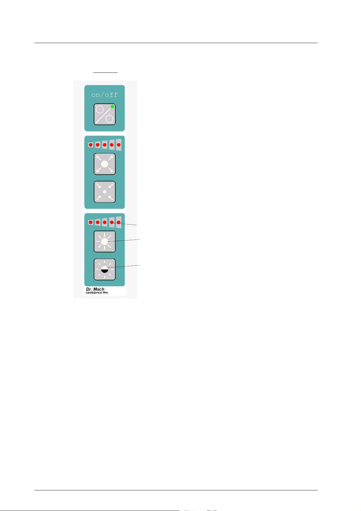
Key pad
1
2
3
Dr. Mach
Lamps and Engineering
2.6 Adjusting the light intensity
(for F/H- and DF/H-models only)
Select the desired light intensity before the operation.
At these models the adjustment is done by the keypad at the cardanic bow. The intensity can be adjusted continuosly between 50% and 100%.
Press push button 2 to increase the light intensity
and press push button 3 to reduce the light intensity.
The set light intensity is shown by LED-display 1.
For other light models we recommend a dimmer in
the supply line.
59270001 Edition 06 28.09.2004 / Bak page 8/26

Mach M5
2.7 Positioning
1
Dr. Mach
Lamps and Engineering
Use the sterile handle 2 or the handle rails 1 to
1
position the lamp.
Use the handle rail to position the lights before the
operation.
Use the sterile handle for positioning during the
operation. This handle can be removed for sterilisation.
2
1,4m
(1,5m)
1m
0,7m
(0,6m)
0
The working distance for the F-lamps is 0,7m to
1,4m.
The working distance for the DF-lamps is 0,6m to
1,5m.
The handle is supplied with a detectable mechanical
catching. When the handle catches in this position,
the lamp is optimally set for a working distance of 1
meter.
Two or more lamps can be used for an intensive
illumination of large operation fields.
It is also possible to illuminate two operation fields
simultaneously.
59270001 Edition 06 28.09.2004 / Bak page 9/26
Mach M5
Dr. Mach
Lamps and Engineering
3. Cleaning
V
1
Cleaning / disinfection and sterilisation
Basics
Efficient cleaning / disinfection is an essential requirement for effective sterilisation of the handle.
Within the scope of responsibility for the sterility of the products it should be noted that only sufficiently
validated equipment and product specific processes are used for cleaning / disinfection and that the validated parameters are complied with in every cycle.
In addition, the hospital / clinic hygiene regulations must be observed.
Cleaning / disinfection
Cleaning and disinfection must be carried out immediately after use.
A mechanised process (disinfector) should be used for cleaning / disinfection. The efficiency of the process used must be recognised and validated in principle (e.g. listed under disinfectants and disinfection
procedures tested and recognised by Robert-Koch-Institute / DGHM).
When using other procedures (e.g. a manual procedure), proof and process efficiency in principle must
be provided within the scope of validation.
Proof in principle of the suitability of the handles for efficient cleaning / disinfection was provided using a
cyclic cleaning system (Netsch-Bellmed T-600-IUDT/AN, programme 2 for small parts; code B).
It is not allowed to use agents / disinfectants, which contain the following substances, as these may
cause changes in the material:
- High-concentration organic and inorganic acids
- Chlorinated hydrocarbons
- 2-ethoxyethanol
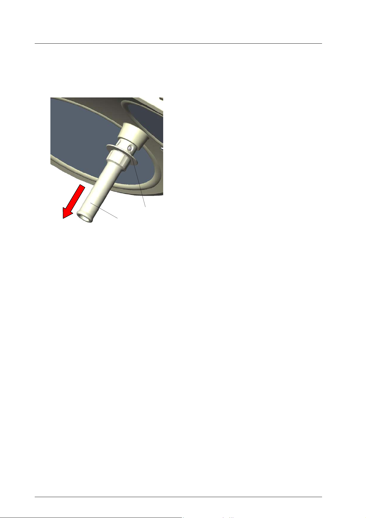
3.1 Sterilisable handle
At delivery the lamp is equipped with the handle
sleeve 1. The handle sleeve is removable and sterilisable. Before using the first time and before every
use the handle sleeve must be cleaned, disinfected
and sterilised.
The handle sleeve must be removed for sterilisation:
• To remove press the lock V and pull off the ster-
ilisable handle sleeve 1 while keeping the lock
pressed.
• To attach, push on and slightly twist the handle
until the lock V engages securely.
Handles often become unsterile during an operation.
Therefore always keep additional handles available
for exchange.
59270001 Edition 06 28.09.2004 / Bak page 10/26

Mach M5
Dr. Mach
Lamps and Engineering
When cleaning / disinfecting, the following procedures must be followed:
Process Time (sec.)
Zone 1 Pre-rinse, external, cold, 10 – 15°C 45 Washing, acidic, external 35°C 120 Draining time 10 Re-rinse, external approx. 80°C *10 Draining time *15 Re-rinse, external approx. 80°C *15 Draining time 15
Zone 2 Washing, alkaline, external, 93°C 135 Draining time 10 Re-rinse, external, acidic, 90°C 10 Draining time 15 Re-rinse, external 90°C 15 Draining time 15
Zone 3 Drying, external 100 – 120°C 200
Zone 4 Drying, external 100 – 120°C 200
Door open / close & transport 60 (sluice discharge)
Cycle time overall ca. 290
* When occupying the disinfection zone (washing zone 2), the re-rinse and draining times will depend on
the respective objects being washed therein!
≈ 5 minutes
Sterilisation
Only previously cleaned and disinfected handles may be sterilised.
The handles are placed in a suitable sterilisation pack (one-way sterilisation pack, e.g. foil / paper sterilisation bags, single or double pack) in accordance with DIN EN 868 / ISO 11607 for steam sterilisation
and then sterilised.
Use only the sterilisation procedure listed below for sterilisation. Other sterilisation procedures (e.g. ethylene oxide, formaldehyde and low-temperature plasma sterilisation) are not permissible.
Steam sterilisation procedure
Validated in accordance with DIN EN 554/ISO 11134
Maximum sterilisation temperature 134°C
Proof in principle of the handles’ suitability for effective sterilisation was provided using a fractional vacuum process (Euroselectomat 666 by MMM Münchner Medizin Mechanik GmbH, sterilising temperature
134°C, holding time 7 min.)
Inspection / durability
The handles should be inspected for damage and changed before re-use, if required.
The handles may be cleaned / disinfected, sterilised and re-used for a maximum of 1000 times. If the
handles are re-used more than 1000 times, then this will be the responsibility of the hospital / clinic.
59270001 Edition 06 28.09.2004 / Bak page 11/26

Mach M5
Alc. ≤ 20 %
2
Dr. Mach
Lamps and Engineering
3.2 Lamp housing, dispersing lens
and support system
The Dr. Mach OT-lamp system has a high-quality
surface, which can be cleaned with conventional
cleaning agents.
The lens system 2 is made of a high-quality plastic.
Pay attention to the following during cleaning:
- Never wipe over the lens system 2 with a dry
cloth (always clean with a wet cloth).
- Only use disinfectants with less than 20% alco-
hol.
Wipe the lens system 2 after cleaning with an antistatic, non-fluffy cloth.
4. Maintenance
DR. MACH lamps are supplied with brakes on the suspension fixture and on the lamp housing. Adjust
these brakes, if necessary, after installation.
If the lamp is difficult to move or if it does not keep its position, the brake forces should be adjusted.
The lamps and suspension fixtures have been designed and built, so that regular maintenance intervals
are not necessary.
In order to keep the system easy-running throughout its life span, we recommend that the hinges should
be greased once a year with acid-free grease.
Attention: Before dismounting the lamp, set the height adjustment of the spring arm to horizontal
position (see mounting instructions „Ceiling attachment – wall attachment“).
When adjusting the brakes or the hinges at the ceiling attachment, please consult the mounting instructions “Ceiling attachment with heavy central axis” or “Ceiling attachment – wall attachment”.
4
4.1 Adjustments at the lamp head
The fine adjustment for handling the lamps can be
carried out at points 3 and 4.
To adjust the brakes use a screw driver with approriate size.
If you cannot adjust the brakes at points 3 and 4 as
tight as necessary anymore, you will have to replace
them.
3
59270001 Edition 06 28.09.2004 / Bak page 12/26
Mach M5
4.2 Changing of spare parts
1
Dr. Mach
Lamps and Engineering
4.2.1 Changing the halogen bulbs
Dr. Mach uses special halogen bulbs as illuminants.
Only original Dr. Mach replacement bulbs may
be used.
The use of other bulbs can lead to a considerable
reduction of the light power and increase in the
thermal load.
The halogen bulbs have a service life of approx.
1200 hours. We recommend changing all halogen
bulbs in a lamp at the same time to keep maintenance work to a minimum.
To change the halogen bulbs proceed as follows:
• Turn off the lamp.
ATTENTION: Parts of the housing and the
halogen bulb may be very hot immediately
after use.
• Turn the lamp, so the light outlets point to the
ceiling.
• Turn screw 1 anticlockwise with an appropriate
screw driver.
Remark:
In case there is no screw driver available, you
can use a coin.
• By turning the screw 1 anticlockwise, the optic
ring 2 turns clockwise off the lower housing
part.
• Remove the optic ring 2 by pulling it upwards.
2
59270001 Edition 06 28.09.2004 / Bak page 13/26
Mach M5
3
5
Dr. Mach
Lamps and Engineering
• Now you can see the open reflector 3 in front
of you.
ATTENTION: Do not touch the inner surface
of the reflector, otherwise the surface can
be damaged.
• Tilt the shadower 4 off-center, until it snaps in
in the provided groove.
• Pull the halogen bulb 5 carefully off its socket.
ATTENTION: Never touch new halogen
bulbs with your fingers. Always use the
original packaging or a clean cloth.
• Carefully insert the new halogen bulb (22,8V,
77W) in the socket.
• Tilt the shadower 4 in its original position.
4
• Mount the optic ring 2 in reverse order (anti-
clockwise rotation).
For mounting position the optic ring 2, so the
1
6
2
toothed wheel segment 6 of the ring and the
toothed wheel 7 in the lower housing part
work into each other.
• Fix the optic ring by turning the screw 1 clock-
wise.
• Check the function of the new halogen bulb.
7
59270001 Edition 06 28.09.2004 / Bak page 14/26

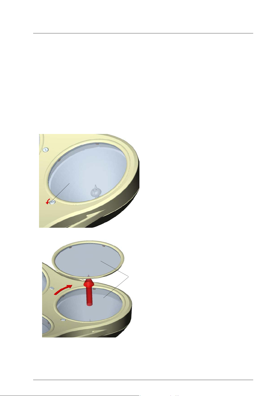
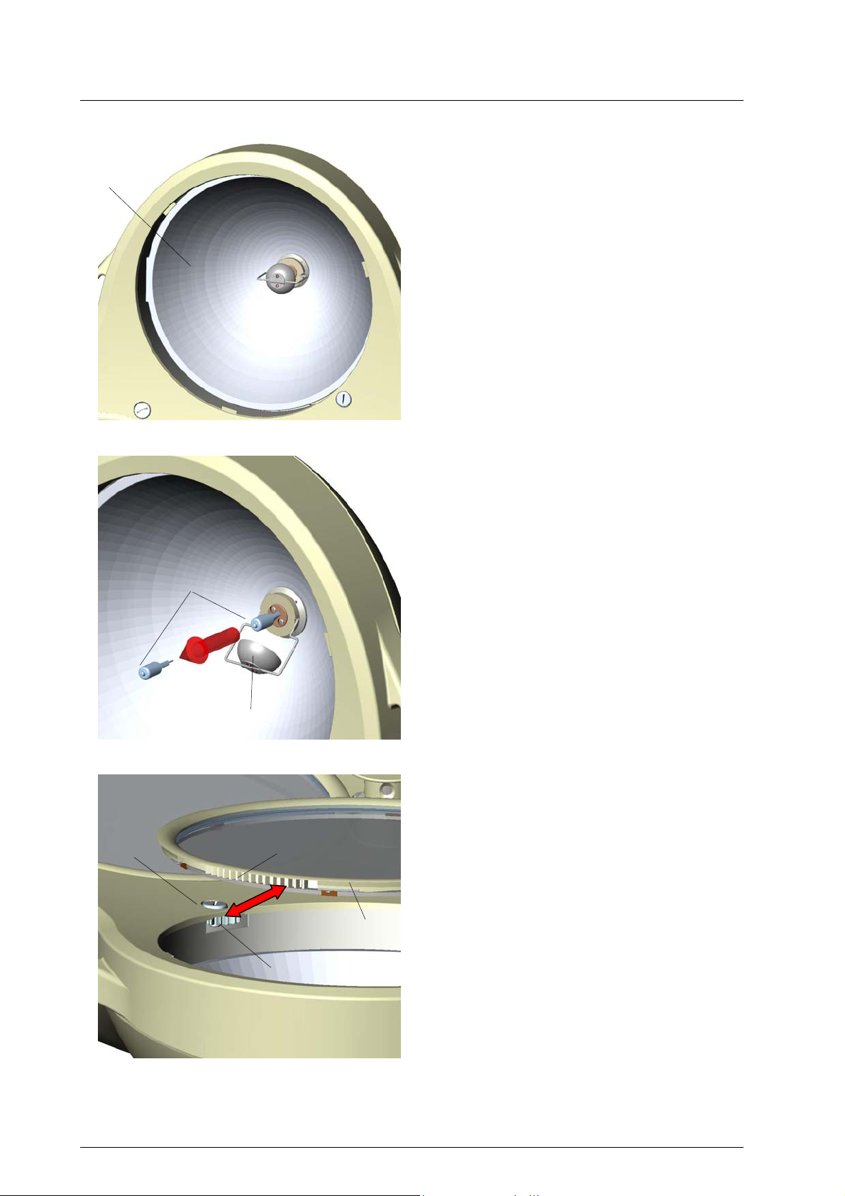
Mach M5
1
Dr. Mach
Lamps and Engineering
4.2.2 Changing the filter disk
The filter disk between reflector and protective disk
prevents a damaging heating of the illuminated area.
ATTENTION!
The lamps must not be used without this filter.
Always place the filter disk on a soft, nonscratching base to preserve its surface.
To change the filter disk proceed as follows:
• Turn off the lamp.
ATTENTION: Parts of the housing and the
halogen bulb may be very hot immediately after use.
• Turn the lamp, so the light outlets point to the
ceiling.
• Turn screw 1 anticlockwise with an appropriate
screw driver.
Remark:
In case there is no screw driver available, you
can use a coin.
• By turning the screw 1 anticlockwise, the optic
ring 2 turns clockwise off the lower housing part.
• Remove the optic ring 2 by pulling it upwards.
2
59270001 Edition 06 28.09.2004 / Bak page 15/26

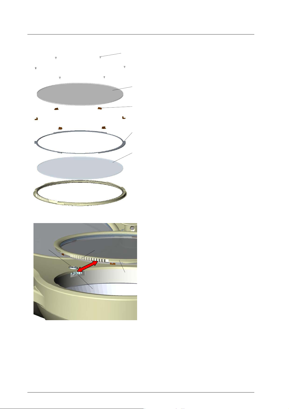
Mach M5
Dr. Mach
Lamps and Engineering
• The filter disk 3 is held by six retaining angles
4, the retaining angles are fixed with six re-
cessed head screws.
• Loosen the screws at three adjacent retaining
angles 4 and turn these angles as shown in the
left drawing.
4
1
4
3
Lift the filter disk 3 carefully and pull it off the
3
•
other three retaining angles.
Mount the new filter disk in reverse order.
•
ATTENTION: Only use filter disks that have
been cleaned properly (see chapter 3.2).
• Mount the optic ring 2 in reverse order (anti-
clockwise rotation).
For mounting position the optic ring 2, so the
5
2
toothed wheel segment 5 of the ring and the
toothed wheel 6 in the lower housing part
work into each other.
• Fix the optic ring by turning the screw 1 clock-
wise.
6
59270001 Edition 06 28.09.2004 / Bak page 16/26

Mach M5
1
Dr. Mach
Lamps and Engineering
4.2.3 Changing the dispersing lens
The dispersing lens is made of a high-quality plastic. In case the dispersing lens looses its optical
characteristics, this can reduce the luminous intensity and the light quality provided.
It may be necessary to exchange the dispersing
lens.
Always place the dispersing lens on a soft,
non-scratching base to preserve its surface.
To change the dispersing lens proceed as follows:
• Turn off the lamp.
ATTENTION: Parts of the housing and the
halogen bulb may be very hot immediately
after use.
• Turn the lamp, so the light outlets point to the
ceiling.
• Turn screw 1 anticlockwise with an appropriate
screw driver.
Remark:
In case there is no screw driver available, you
can use a coin.
• By turning the screw 1 anticlockwise, the optic
ring 2 turns clockwise off the lower housing
part.
• Remove the optic ring 2 by pulling it upwards.
2
59270001 Edition 06 28.09.2004 / Bak page 17/26
Mach M5
Dr. Mach
Lamps and Engineering
3
• Loosen the six screws 3 and remove them.
• Lift the filter disk 4 off the six retaining an-
gles 5.
Always place the filter disk on a soft, nonscratching base to preserve its surface.
4
5
6
7
• Remove the six retaining angles 5.
• Remove the retaining ring 6 of the dispersion
lens.
• Remove the dispersion lens 7.
Always place the dispersion lens on a soft,
non-scratching base to preserve its surface.
• Mount the new dispersion lens 7.
ATTENTION: Only use dispersion lenses,
that have been cleaned properly (see chapter 3.2).
• Mount the retaining ring 6, the retaining an-
gles 5, the filter disk 4 in reverse order and fix
the retaining angles with the six screws 3.
• Mount the optic ring 2 in reverse order (anti-
clockwise rotation).
For mounting position the optic ring 2, so the
1
8
toothed wheel segment 8 of the ring and the
toothed wheel 9 in the lower housing part
work into each other.
• Fix the optic ring by turning the screw 1 clock-
2
wise.
9
On request of the customer there are spare parts lists and wiring diagrams available for the lamps
Mach M5 F / Mach M5 DF.
59270001 Edition 06 28.09.2004 / Bak page 18/26

Mach M5
5.1 Technical data
Mach M5 DF / M5 DF/H
Dr. Mach
Lamps and Engineering
5. Data
Central light intensity
at a distance of 1 meter
Light field diameter d10 172,5 mm
Light field diameter d50 96 mm
Light intensity with one shadower 127.500 Lux
Light intensity with two shadowers 85.600 Lux
Light intensity on the ground of a
normed tube
Light intensity on the ground of a
normed tube with one shadower
Light intensity on the ground of a
normed tube with two shadowers
Illumination depth 715 mm
Colour rendering index Ra
at 4300 Kelvin
160.000 Lux
157.000 Lux
125.000 Lux
84.600 Lux
96
Colour rendering index R9
at 4300 Kelvin
Focusable
light field size
Colour temperature (Kelvin) 4300 K
Radiation intensity in field
at 100.000 Lux
Temperature increase
in head area
Total power consumption 231 VA
Number of bulbs:
Halogen 22,8/24V 77W
Working distance 60-150 cm
Height adjustment 118 cm
≥ 90
17-35 cm
380 W/m2
2 °C
3
59270001 Edition 06 28.09.2004 / Bak page 19/26

Mach M5
5.2 Electrical data
Mach M5 DF / M5 DF/H
Power consumption 231 W
Voltage AC/DC 22,8 V
Current 10,1 A
Halogen bulb 22,8 V / 77 W
Frequency 50/60 Hz
Degree of protection Type B
Class of protection I.
Dr. Mach
Lamps and Engineering
5.3 Environemental conditions
Operation
Temperature +10°C +40°C
Relative athmospheric humidity 30 % 75 %
Air pressure 700 hPa 1060 hPa
Min. Max.
Transport / storage
Temperature -10°C +50°C
Relative athmospheric humidity 20 % 90 %
Air pressure 700 hPa 1060 hPa
Min. Max.
5.4 General remarks
When using more than one OT-lamp at the same time (OT-lamp combinations), please make sure that
the total radiation intensity in field is less than 1000 W/m2, to avoid further temperature increase in the
wound field.
When installing an OT-lamp, its fail-safety must be guaranteed according to DIN VDE 0100-710 (former
DIN VDE 0107).
Protective conductor
59270001 Edition 06 28.09.2004 / Bak page 20/26

Mach M5
Dr. Mach
Lamps and Engineering
6. CE-mark
The products Mach M5 comply with the standards 93/42/EEC for medical products of the
European Community’s Council. Dr. Mach applies the standard EN 60601-2-41.
Dr. Mach GmbH is certified according to DIN EN 46001:1996 and DIN EN ISO
13485:2001.
7. Disposal
The OT-lamp doesn’t contain any dangerous goods.
The components of the OT-lamp should be properly disposed at the end of its shelf-life.
Make sure, that the materials are carefully separated.
The electrical conducting boards should be submitted to an appropriate recycling proceeding.
The rest of the components should be disposed according to the contained materials.
59270001 Edition 06 28.09.2004 / Bak page 21/26

Mach M5
Dr. Mach
Lamps and Engineering
8. Spare parts
4,5
3
25 6
7
18
15,16
1,2
20,21,22
23,24
8
9
10
17
11
12,13
19
59270001 Edition 06 28.09.2004 / Bak page 22/26
14
40

Mach M5
26
Dr. Mach
Lamps and Engineering
27
28
29
30,31
32
34
35,36
33
59270001 Edition 06 28.09.2004 / Bak page 23/26

Mach M5
Dr. Mach
Lamps and Engineering
9. Spare parts list
Item Qty. Name EDVNO Remarks
1 1 Lower housing part for lamp without camera 27012201
2 1 Lower housing part for lamp with camera 27012203
3 1 Upper housing part 27011201
4 1 Cover for lamp without camera 27088201
5 1 Cover for lamp with camera 27088001
6 1 Sealing cord RAL 5018 27088301 Pasted with upper
housing part
7 6 Lock 27087001
8 3 Reflector 27060204
9 3 Shielding plate 27022001
10 3 Conversion filter D284 Califlex Eco 67390204
11 3 Retaining ring 27021203
12 18 Retaining angle 27021204
13 18 Cheese head screw DIN912 M3x6:A2 with laquer 65052098
14 3 Protective disk 27021201
15 1 Bowden-control DF 27080002 DF-lamps only
16 1 Bowden-control F 27080001 F-lamps only
17 1 Gear motor 67030108 DF-lamps only
18 2 Micro switch 67340015 DF-lamps only
19 3 Gearwheel 27021202
20 1 Dimmer board OPLSD I. 67250109 F- ,DF/H lamps with
motor control
21 1 Dimmer board OPLSD II. 67250110 F-, DF/H lamps with
Bowden-control
22 1 Board OPLSD IV. 67250112 F, DF-lamps without
light intensity control
23 1 Lamp bow 27101001
24 1 Lamp bow for central spring arm 27100001 For low room height
25 1 Cardan bow 27111001
26 3 Halogen bulb 22,8V / 75W 67100207
27 3 Ceramic lamp socket with cable 67320007
28 3 Shadower 27061001
29 3 Screw 27089203
30 1 Keypad holder incl. keypad F/H-lamps only
31 1 Keypad holder incl. keypad DF/H-lamps only
32
33
34 1 Sterilisable handle 21150002
35 1 Coupling for sterilisable handle DF 20220001 DF-lamps only
36 1 Coupling for sterilisable handle F 20220002 F-lamps only
37 1 Toroid transformer 300VA 230V 67010109 To be mounted on the
38 1 Block transformer 300VA 230V 67010208 To be mounted inside
39 1 Transformer housing for block transformer 300VA 67610101 Not shown
40 3 Retaining ring, complete 27021001 Complete with con-
1 Brake screw 21118204
1 Press pin 21118003
1 Brake screw 27089205
1 Press pin 21118003
ceiling flange
(accessories)
the transformer
housing (accessories)
(accessories)
version filter and pro-
tective disk
59270001 Edition 06 28.09.2004 / Bak page 24/26

Mach M5
Setting the primary voltage at the
block transformer 300VA
Clamps on the transformer
Dr. Mach
Lamps and Engineering
10. Appendix
3
Pos.1 earthing connection at the trans-
former
Pos.2 primary side
Pos.3 secondary side
1
2
• Connect the transformer to earth. Use the provided clamps pos.1 at the transformer, respectively at
the transformer plate.
See also the explanations on page 19/46 of the mounting instructions “Ceiling and wall attachment” no. 59500001 / edition 05.
Overview of the possible settings of the primary voltage
Setting for115V
Setting for 132V
59270001 Edition 06 28.09.2004 / Bak page 25/26

Mach M5
Dr. Mach
Lamps and Engineering
Setting for 230V
Setting for 247V
59270001 Edition 06 28.09.2004 / Bak page 26/26
 Loading...