

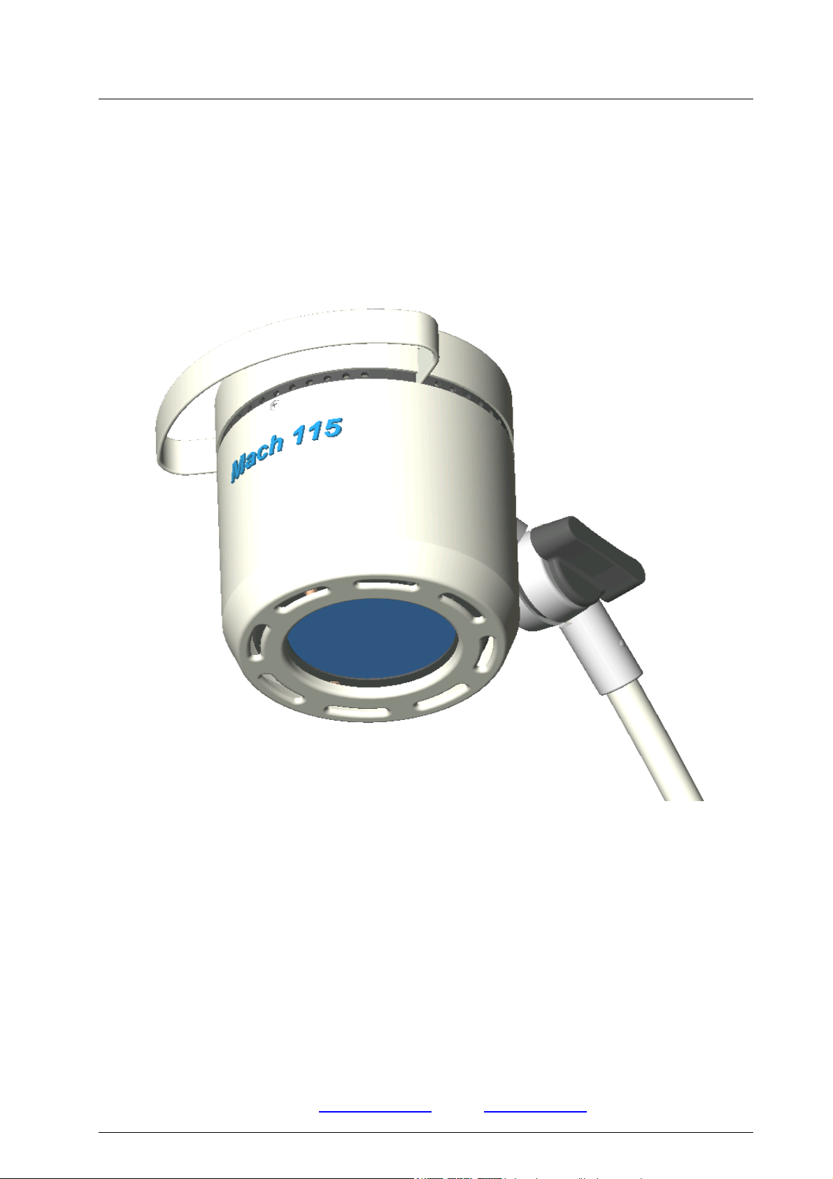
Mach 115
Dr. Mach
Lamps and Engineering
Directions for use
MACH 115
Halogen Spot Lamp
Stand lamp ................................................................................................ Item no. 1151101200
Wall lamp...................................................................................................Item no. 1151102100
Table lamp.................................................................................................Item no. 1151102500
Attachment to supply rail ........................................................................Item no. 1151102601
Attachment to round or rectangular tube ..............................................Item no. 1151102602
Attachment with screw-on plate .............................................................Item no. 1151102604
Dr. Mach
59040001 Edition 10 17.12.2004 / Bak Page 1/18
GmbH u. Co., Floßmannstrasse 28, D-85560 Ebersberg
Tel.: +49 (0)8092 2093 0, Fax +49 (0)8092 2093 50
Internet: www.dr-mach.com, E-mail: info@dr-mach.de

Mach 115
Dr. Mach
Lamps and Engineering
List of contents
1. Safety instructions .......................................................................................... Page 3
2. Mounting instructions ..................................................................................... Page 4
2.1 Mounting the stand................................................................................... Page 4
2.2 Mounting the lamp.................................................................................... Page 5
2.3 Wall attachment........................................................................................ Page 5
2.4 Table attachment...................................................................................... Page 5
2.5 Rail attachment ........................................................................................ Page 5
2.6 Round and rectangular tube attachment .................................................. Page 5
2.7 Attachment of screw-on plate................................................................... Page 5
3. Directions for use ........................................................................................... Page 6
3.1 Stand foot ................................................................................................. Page 6
3.2 Stand tube ................................................................................................ Page 6
3.3 Operating the lamp................................................................................... Page 7
3.3.1 ON/OFF switch ................................................................................. Page 7
3.3.2 Positioning ........................................................................................ Page 7
3.3.3 Electronic light intensity control ........................................................ Page 8
4. Cleaning ......................................................................................................... Page 8
4.1 Stand ........................................................................................................ Page 8
4.2 Lamp head ............................................................................................... Page 8
4.3 Protective disk (filter disk) ........................................................................ Page 8
5. Maintenance................................................................................................... Page 9
5.1 Settings at the stand................................................................................. Page 9
5.2 Changing of spare parts ........................................................................... Page 9
5.2.1 Changing the halogen bulb............................................................... Page 9
5.2.2 Changing the fuses........................................................................... Page 10
5.2.3 Changing the protective disk (filter disk)........................................... Page 10
6. Data................................................................................................................ Page 11
6.1 Technical data .......................................................................................... Page 11
6.2 Environmental conditions ......................................................................... Page 12
7. Characteristics................................................................................................ Page 12
7.1 Specification of bulb ................................................................................. Page 12
7.2 Specification of fuse ................................................................................. Page 12
7.3 CE-mark ................................................................................................... Page 13
8. Disposal.......................................................................................................... Page 13
9. Spare parts..................................................................................................... Page 14
9.1 Lamp head / arm ...................................................................................... Page 14
9.2 Stand foot, stand tube .............................................................................. Page 15
9.3 Transformer with switch / potentiometer .................................................. Page 15
9.4 Mounting possibilities ............................................................................... Page 16
9.5 Spare parts list ......................................................................................... Page 17
59040001 Edition 10 17.12.2004 / Bak Page 2/18

Mach 115
Dr. Mach
Lamps and Engineering
1. Safety instructions
Please pay attention to the directions for use when handling the lamp.
Attention:
This device is not suitable for use in hazardous locations.
The lamp is classified as a group 1 device according to the MPG
(law for medical products).
The lamp may be connected to mains only after the complete mounting of the stand
and the lamp.
Repairs to the lamp and special installation work on the reflector or at the transformer
should only be carried out by ourselves or a company expressly authorised by ourselves.
The manufacturer is only responsible for the safety of the lamp and the stand if repairs
and alterations have been carried out by themselves or a company who can guarantee
that the safety regulations have been observed.
The manufacturer is not liable for personal or material damages if the lamp or the
stand is misappropriately or incorrectly operated or misused.
General instructions
All Dr. Mach stand lamps are supplied with
all installation and connection parts and
components.
For packaging reasons, the five-foot stand is
supplied in dismantled state. The stand tube
is always assembled as a unit and only
needs to be attached to the foot with the
lower fastening screw.
The lamp is supplied with integrated connection lead and earthed plug.
The socket to be used for the lamp must be
installed according to the requirements stipulated by the IEC or VDE 0107.
Please check that the earthed socket is
available within the working area of the lamp.
59040001 Edition 10 17.12.2004 / Bak Page 3/18
Mach 115
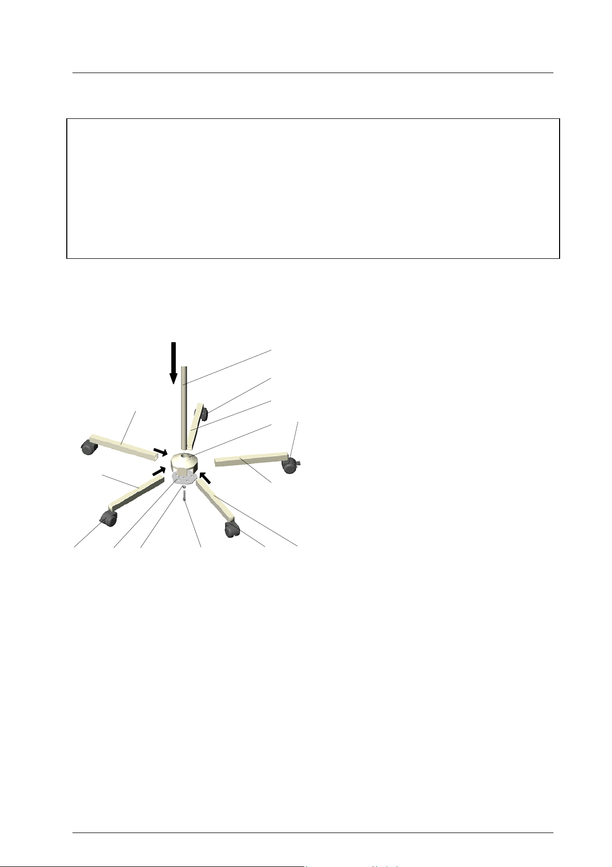
2. Mounting instructions
Extent of supply
• 1x 5-footed plastic central base
• 2x extension arms with blocking rollers
• 2x extension arms with electrically conductive rollers
• 1x extension arm with roller
• 1x cam catch plate
• 1x cheese head screw M8 with lock washer
• 1x stand tube
• Lamp head with arm
• Mounting instructions/Instructions for use – lamp head and stand
2.1 Mounting the stand
42
37
34 35
41
36
33
45
40
32
39
44 38
For mounting the stand proceed as follows:
• Place the central base 32 onto the stand
tube ∅25 33. The stiffness is to ensure a
tight fit that is free from any movement.
• Pre-mount the cam catch plate 34 (cams
point inwards), with the lock washer 35 and
43
cheese head screw M8 36, so that the extension arm 37 can still fit easily into the
central base. Insert the extension arm 37
into the central base from above holding
the cam catch plate 34 against from the
opposite side.
• Insert the other 4 extension arms 38-41 in
the sequence shown in the left figure into
the central base. The extension arms are
held by the cams of the cam catch plates.
Remark: Mount the two locking rollers 42
and 43, and the two electrically conductive
rollers 44 and 45 as shown in the figure (not
next to each other).
• Tighten the catch plate with an Allen key
SW6 (approx. 15Nm).
The cams of the catch plate must mate with
the drill holes of the extension arms so that
every extension arm is tightly fitted to both
the central base and stand tube.
The cams also prevent the extension arms
from being pulled out.
Dr. Mach
Lamps and Engineering
59040001 Edition 10 17.12.2004 / Bak Page 4/18
Mach 115
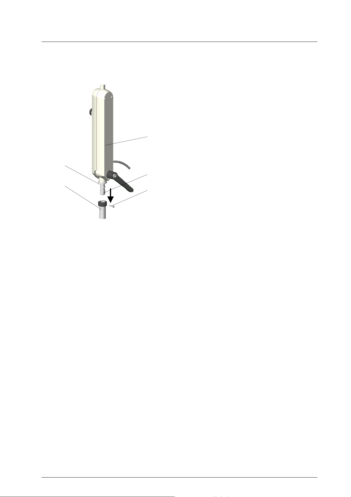
2.2 Mounting the lamp
N
27
Z
Dr. Mach
Lamps and Engineering
Tighten screw S in the mounting device (stand,
wall, table, rail, round and rectangular tube,
screw-on plate) after the lamp has been attached. This prevents the lamp from being unintentionally removed.
Make sure that joint Z at the lower side of
transformer housing 27 is fully inserted into
tube A, so that the safety screw S engages
properly in the provided groove N.
A
S
2.3 Wall attachment
• Mark the position of the holes to be drilled in the wall using the wall bracket.
• Drill the holes and insert dowels.
Remark: Use the three screws and dowels provided to attach the wall bracket.
• For mounting the lamp see point 2.2.
2.4 Table attachment
• Screw table clamp onto table.
• For mounting the lamp see point 2.2.
2.5 Rail attachment
• Attach light mounting in the desired position on the rail.
• For mounting the lamp see point 2.2.
2.6 Round and rectangular tube attachment
• Screw light mounting in desired position onto tube.
• For mounting the lamp see point 2.2.
2.7 Attachment of screw-on plate
• Drill attachment holes and attach with screws.
• For mounting the lamp see point 2.2.
59040001 Edition 10 17.12.2004 / Bak Page 5/18
Mach 115
A
Dr. Mach
Lamps and Engineering
3. Directions for use
A
S
34
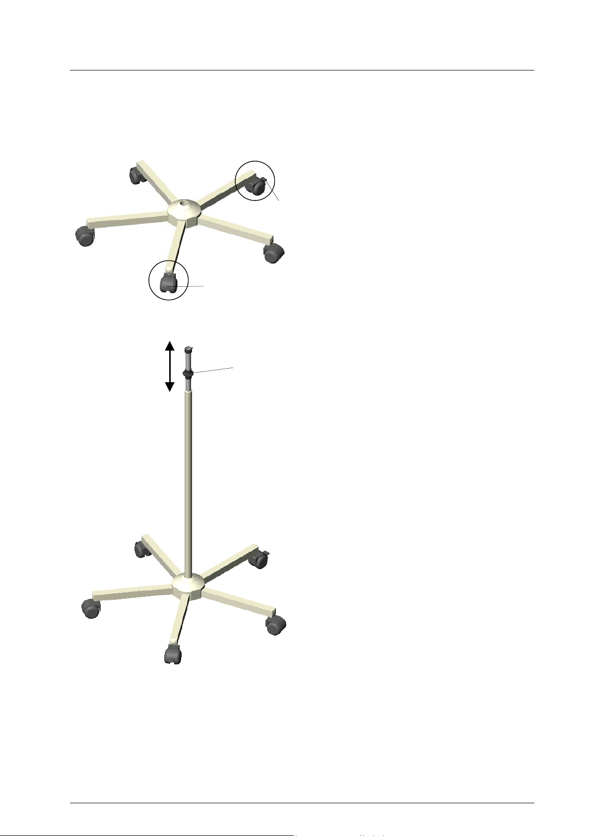
3.1 Stand foot
The five-foot stand is equipped with two opposing braked wheels A.
S
Set the brake by pressing the pedal S on the
roller. Unlock by lifting the pedal again.
3.2 Stand tube
The stand tube can be adjusted continuously in
height and fixed in the precisely required position, needing only one hand.
The height is adjusted by lifting the slip button
34. The position is automatically fixed on letting
go.
As long as the slip button 34 is raised, the extension tube can be pulled off or inserted into
the stand tube.
59040001 Edition 10 17.12.2004 / Bak Page 6/18

Mach 115
Dr. Mach
Lamps and Engineering
24,29
3.3 Operating the lamp
3.3.1 ON/OFF switch
Push rotary type push button 29 on switch 24 at
the transformer housing to turn the lamp on and
off.
16
VK1
04
16
3.3.2 Positioning
To position the lamp use clamping lever 20 at the
G116
G2
18
G
VK2
transformer housing, The clamping lever at the
self-locking joint G2as well as the wing screw 16
at the self-locking joint G1.
Use handle 04 to position the lamp head as desired.
20
In case the winged screws 16 have been loosened more than necessary, it is possible, that
bolt 16 no longer fit in the guidance of the joint G.
Before tightening the winged screw 16 again,
always make sure that square VK1 of bolt 16 fits
with square VK2 of the joint G.
Notice the mounting order of the washers:
plate spring, washer, plate spring, winged
screw 16.
59040001 Edition 10 17.12.2004 / Bak Page 7/18

Mach 115
Dr. Mach
Lamps and Engineering
3.3.3 Electronic light intensity control
The lamp is supplied with an electronic light intensity control.
To activate the light intensity control, turn rotary
type push button 29 at the transformer housing:
• Turn to the left: light intensity decreases;
• Turn to the right: light intensity increases.
29
4. Cleaning
4.1 Stand
The surface of the stands can be easily kept clean by simply wiping with a damp cloth. You can
use conventional cleaning agents.
In case of disinfection only use disinfectants with less than 20% alcohol.
4.2 Lamp head
The lamp has a high-quality surface, which can
be cleaned with conventional cleaning agents.
Only use disinfectant with less then 20% alcohol.
4.3 Protective disk (filter disk)
The protective disk 10 is made of an highquality plastic, the filter disk 30 is made of high
quality glass. For cleaning use lukewarm water
10,30
Alc. ≤ 20 %
and a soft viscose sponge. Pay attention to the
following during cleaning:
- Wipe over the protective disk 10 (filter disk
30) with a wet cloth (never use a dry cloth!).
- Only use disinfectant with less then 20%
alcohol.
Wipe protective disk 10 (filter disk 30) after cleaning with an antistatic, non-fluffy cloth.
59040001 Edition 10 17.12.2004 / Bak Page 8/18

Mach 115
Dr. Mach
Lamps and Engineering
5. Maintenance
The lamp is constructed in such a way, that regular service intervals are not required.
5.1 Settings at the stand
♦ One-handed height adjustment
Adjusting the spring force at these stands is
not possible.
It is usually not necessary to adjust the spring
force at stands with one handed height adjustment.
13
5.2 Changing of spare parts
5.2.1 Changing the halogen bulbs
Dr. Mach uses special halogen bulbs as illuminants.
Only original Dr. Mach replacement bulbs may
be used.
The use of other bulbs can lead to a considerable reduction of the light power and increase in
the thermal load.
06
13
01
Attention! Disconnect from mains before
changing the bulb.
To change the bulb proceed as follows:
• Loosen three recessed head screws 13 and
remove the housing lower part 01.
• Pull out carefully halogen bulb 06 (12V/
35W).
• Change the halogen bulb.
Make sure that the front side of the halogen bulb is always clean.
• Push housing lower part onto housing upper
part and fix with the three recessed head
screws 13.
Remark:
The halogen bulbs have a service life of approx. 1000 hours without any deterioration in
their luminosity.
59040001 Edition 10 17.12.2004 / Bak Page 9/18

Mach 115
13
27
22,23
08
11
10,30
13
09
01
Dr. Mach
Lamps and Engineering
5.2.2 Changing the fuses
The fuses in the lamp housing prevent the transformer burning through in the event of a short
circuit. The fuses are situated in the transformer
housing 27.
Attention! Disconnect from mains before
changing the fuses.
Visible fuse 5x20/T0,315A/250V for 230V
If the halogen bulb no longer burns, check the
bulb first, then the fuses.
To change the fuses proceed as follows:
• Turn the black fuse holder 23 ¼ of a rotation
anticlockwise with a screwdriver.
• Change fuses 22.
• Insert fuse holder 23 under slight pressure
and rotate in a clockwise direction (bayonet
catch).
5.2.3 Changing the protective disk
(filter disk)
As an option the lamp can be supplied with a
filter disk (no heat protection filter!)
Remark: In case of lamps without filter disk
the thermal load in the wound area increases.
To change the protective disk (filter disk) proceed as follows:
• Loosen three recessed head screws 13 and
remove the housing lower part 01.
• Loosen three nuts 08 at the cooling body 09.
• Remove heat-protection mounting 11.
• Change protective disk 10 (filter disk 30).
• Fit heat-protection ring 11 and nuts 08 as
shown in the figure.
• Tighten nuts 08 very carefully by hand, until
the disk just starts to turn.
• Push housing lower part onto housing upper
part and fix with the three recessed head
screws 13.
Remark:
Only use protective disks (filter disks) that
have been cleaned according to point 4.3.
59040001 Edition 10 17.12.2004 / Bak Page 10/18

Mach 115
6.1 Technical data
Data
Dr. Mach
Lamps and Engineering
6. Data
Five foot stand
Lamp type
Mach 115
Number of
extension arms
Stand foot
Stand tube
Arm +
lamp head
Lamp head Mach 115 – mains voltage 230 Volt
~ Wechselstrom ~ Alternating current
Pr Primärseitig 230V / 0,27A Pr Primary side
Length of
extension arms
Rollers ∅
Approx. length. 95cm – 145cm
Diameter 25mm
Extension yes
Cable connection no
Suitable for
article no.
• arm and Lamp head pre-
Mounting
• arm mounted to stand
1151 1012 00
mounted
5
310mm
50mm
Sek Sekundärseitig 12V AC / 2,91A Sec Secondary side
Leistungsaufnahme 20 – 60VA Power consumption
Hz Hertz – Frequenz 50 / 60Hz Hz Hertz – frequency
Sicherung 5x20 / T0,315A / 250V Fuse
Schutzgrad Type „B“ Class of protection
59040001 Edition 10 17.12.2004 / Bak Page 11/18

Mach 115
Dr. Mach
Lamps and Engineering
6.2 Environmental conditions
Operation
Temperature +10°C +40°C
Relative atmospheric humidity 30% 75%
Air pressure 700 hPa 1060 hPa
Transport / storage
Temperature -10°C +50°C
Relative atmospheric humidity 20% 90%
Air pressure 700 hPa 1060 hPa
Min. Max.
Min. Max.
7.1 Specification of bulb
12V 35W 10°
FRB 8D
Philips
7.2 Specification of fuse
5x20
T0,315A
7. Characteristics
Protective conductor
Switch ON/OFF
Voltage, power
Mains voltage 230 Volt
Visible fuse 5x20
T0,315A 250V
59040001 Edition 10 17.12.2004 / Bak Page 12/18

Mach 115
Dr. Mach
Lamps and Engineering
7.3 CE-mark
The products Mach 115 comply to the standards 93/42/EEC for medical products
of the European Community’s Council.
8. Disposal
The lamp and the stand do not contain any danger goods.
The components of the lamp and the stand should be properly disposed at the end of its shelf
life. Make sure, that the materials are separated accordingly.
Electronic components should be submitted to an appropriate recycling.
The rest of the components should be disposed according to the contained materials.
59040001 Edition 10 17.12.2004 / Bak Page 13/18

Mach 115
9.1 Lamp head, arm
03
Dr. Mach
Lamps and Engineering
9. Spare parts
14 02
04
06
11
10,30
12
13
05
07
08
09
12
13
01
16
15
18
27,28
20
25
26
27,28
29
24
22,23 22,23
16
17
31
32 31
19
59040001 Edition 10 17.12.2004 / Bak Page 14/18

Mach 115
9.2 Stand foot, stand tube
Dr. Mach
Lamps and Engineering
33
9.3 Transformer with switch / potentiometer
34
24
59040001 Edition 10 17.12.2004 / Bak Page 15/18

Mach 115
9.4 Mounting possibilities
Dr. Mach
Lamps and Engineering
36
35
37
38
59040001 Edition 10 17.12.2004 / Bak Page 16/18

Mach 115
Dr. Mach
Lamps and Engineering
9.3 Spare parts list
Item Qty. Name EDVNO Remark
01 1 Housing lower part 04012203
02 1 Housing upper part 04011201
03 1 Head screw 04080201
04 1 Handle 04080206
05 1 Support 04031001
06 1 Halogen bulb 12V 35W 67100202 FRB 8D Philips
07 1 Socket for halogen bulb 12V 35W 67320009
08 3 Nut 65332002
09 1 Cooling body 04012202
10 1 Protective disk Makrolon 01011208
11 1 Heat-protection ring 04012201
12 3 Tubular rivet 65702003
13 3 Recessed head screw M2,5x6 DIN 966:A2 65112022
14 1 Bracket 04142001
15 1 Transversal arm 04148001
16 1 Cap nut 74581002
17 2 Brake ring 74551005
18 1 Clamping lever M8x0,75 65 long 74503005
19 1 T-handle 74501003
20 1 Clamping lever M8x0,75 65 74551009
21
22 2 Fuse 5x20 T0,315A 67370002 for 230V
23 2 Fuse holder 74551008
24 1 Transformer INSTA 40W with potentiometer 67010402
25 1 Strain relief 74551007
26 1 Line cord with converted safety plug 67200201
27 1 Half part of transformer housing 04080209
28 1 Half part of transformer housing 04080210
29 1 Rotary type push button 10160201
30 1 Heat protection filter 01011203 optional
31 2 Plate spring 74551011
32 1 Washer 04080208
33 1 5-foot stand 74905003
34 1
35 1 Wall attachment 01180001
36 1 Rail attachment 04352001
37 1 Table attachment 74451001
38 1 Tube attachment 04352002
Stand tube ∅25mm with extension tube
74953001
59040001 Edition 10 17.12.2004 / Bak Page 17/18

Mach 115
Dr. Mach
Lamps and Engineering
59040001 Edition 10 17.12.2004 / Bak Page 18/18
 Loading...